

Prastel FT30AV User Manual
English
INFRARED BEAM PHOTOCELL FT30AV
General
The photoelectric barrier FT30AV has been projected for applications in which it is necessary to apply two overlapping photocells,
avoiding that they go in collision one with the other. To get such result it is sufficiant to power supply the photocells with 12/24 V~ and
to cross the power supply. (Ex. When the TX and RX of a photocell are power supplied with a black cable around 0 V~ and with a red
cable of 24V~, the TX and the RX of the other photocell will have to have the red cable with 0 V~ and the black cable around 24
V~.)
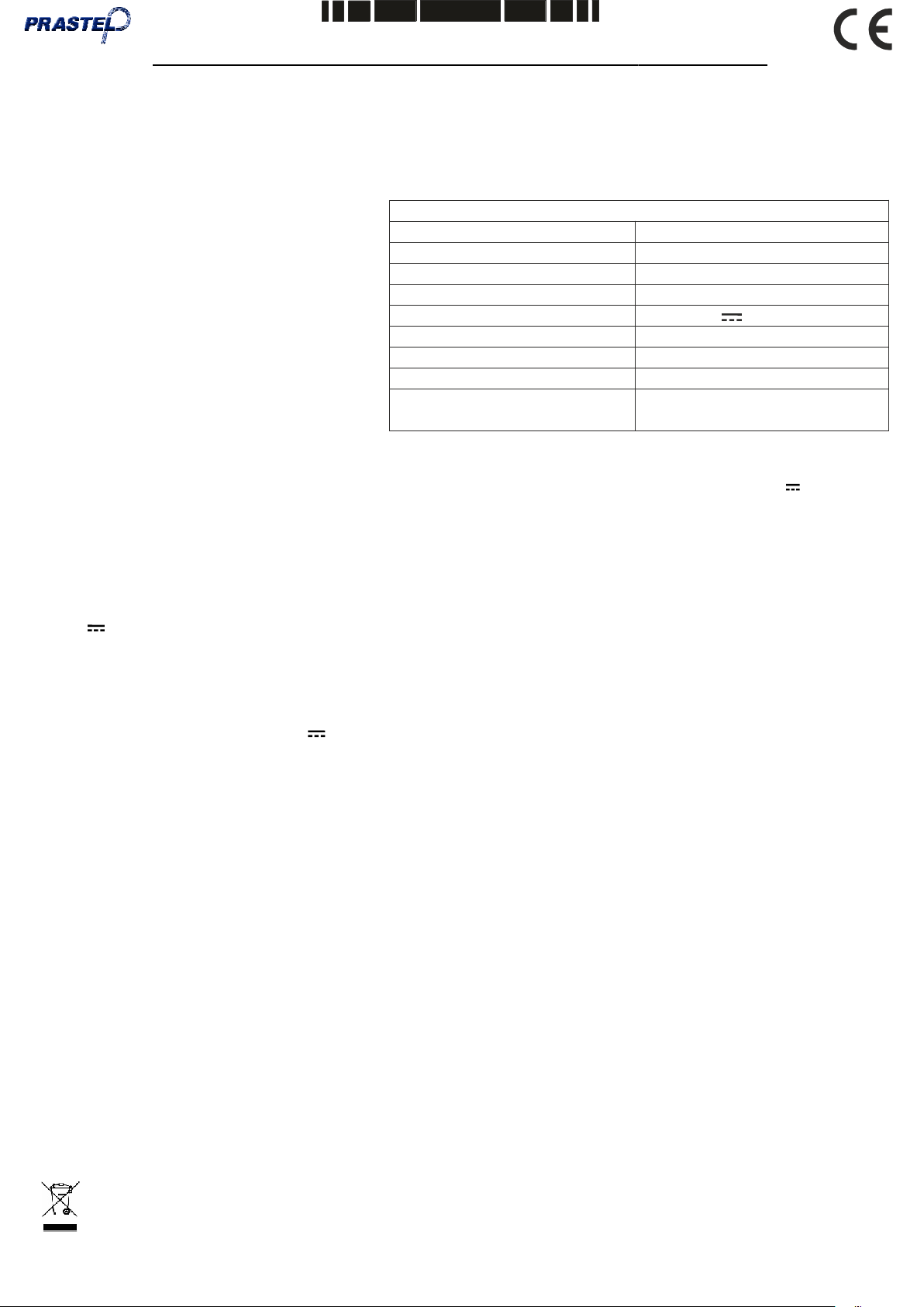
Technical Characteristics
The Photocell Kit Consists of:
1 No. Photocell Receiver
1 No. Photocell Transmitter
1 No. Fixing Kit
4 No. cover-screw cap
1 No. Set of fitting instructions
* The range of the device can be reduced in case
of bad weather conditions (fog, rain, etc..).
INSTALLATION
Transmitter
-Insert the cables in the special seat and make the connections according to the type of application, 12 or 24V~ or V , synchronized
or not synchronized.
-Adjust the cable within the unit to eliminate any surplus.
-Fix the unit.
-Seal the cover & cable entry to prevent insect infestation.
Nominal range: 30 m*
Signal: Modulated infrared
Wave length: 880 nm
Modulation Frequency: 1000 Hz
Supply Voltage: 12 - 24 V / V~
Absorbed Current: 30mA TX; 30mA RX
Temp. Operating Range: -15° C / +60° C
Relay Contact Rating: 1A max; 24V
Humidity: from 5% to 90% no
condensation
Receiver
-Insert the cables into the special seat and make the connections accoriding to the type of application chosen for the transmitter, 12/
24V~ or V , synchronized or not synchronized.
-Adjust the cable within the unit to eliminate any surplus.
-Make sure that the receiver is in frontal position, lined up on the same axis and in the same height of the associated transmitter. Act
on the lens adjustment if necessary (see fig.6-7).
-Seal the cover & cable entry to prevent insect infestation.
Once executed the preceding operations for both Tx and for Rx:
-Power supply the photocells 12-24V~ or V and verify their alignment. If the positioning, the alignment and the connection of the
photocells are correct, the red LED on the receiver will be switched on.
Please note: For the syncronized function, the power supply has to be necessarily of 12/24 V~ (alternating current).
Operational Verification
Fit one of the black plastic photocell covers complete with an opaque diffuser label stuck across the lens.
- Check that the relay works correctly.
- Check that the red led goes out when the beam is broken.
Red led Function:
RED LED LIT: ALIGNED
YELLOW LED ON: NOT ALIGNED OR BAD ALIGNMENT
SECURITY
The 23102160 device cannot be used as security device (EN 12978).
SPARE PARTS
To obtain spare parts contact: Prastel France.
INTENDED USE
The photocell 23102160 has been projected to be used exclusivley as photoelectric barrier to be installed in the areas considered
dangerous and in proximity of the gate/ leaf, it must be used exclusively for the functioning as interposition between transmitter and
receiver (installed according to the above mentioned instructions) and must be power supplied with safety tension.
ENVIRONMENT
Please dispose of this product packaging in a responsible, appropriate way.
CONFORMITIES
The 23102160 photocell conforms to the following: 2004/108/CE (Act on the Electromagnetic Compatibility)
Correct Disposal of This Product (Waste Electrical & Electronic Equipment) - Europe only
(Applicable in the European Union and other European countries with separate collection systems)
This marking shown on the product or its literature, indicates that it should not be disposed with other household wastes
at the end of its working life. To prevent possible harm to the environment or human health from uncontrolled waste disposal, please
separate this from other types of wastes and recycle it responsibly to promote the sustainable reuse of material resources.
67411400P Rev. 02 - 05/2013
Pag. 1
English
Household users should contact either the retailer where they purchased this product, or their local government office, for details of
where and how they can take this item for environmentally safe recycling.
STORING
STORAGE TEMPERATURES
T
min
T
max
Humidity
min
Humidity
max
-20 °C +70 °C 5% no condensation 90% no condensation
When being transported this product must be properly packaged and handled with care
CLEANING AND MAINTENANCE
Cleaning and maintenance of this unit must be carried out at 6 monthly intervals by authorised, qualified personnel. During routine
maintenance the following checks should be made: Correct alignment, sealing, cleanliness of the lenses and internal components.
Any remedial work should be carried out as required.
DECOMMISSIONING
If the 23102160 photocell is to be taken out of service, this work must only be undertaken by authorised, qualified personnel.
NOTE: THE MANUFACTURER CAN NOT BE DEEMED RESPONSIBLE FOR ANY DAMAGE OR INJURY CAUSED BY
IMPROPER USE OF THIS PRODUCT.
Prastel France reserves the right to do changes or variations that may be necessary to its products with no obligation to notice.
32
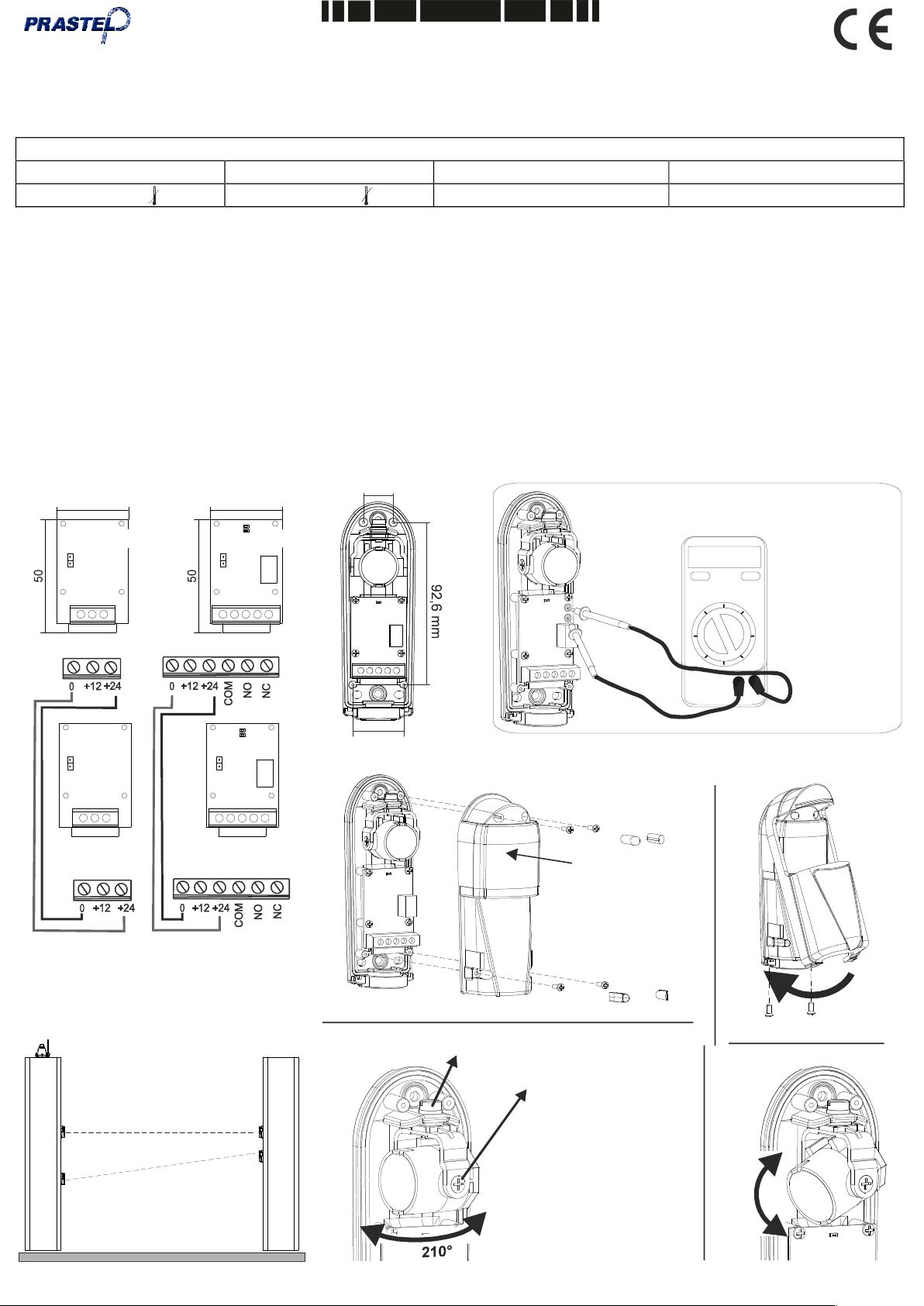
Fig. 2
Tx1
JP1 JP1
1 2 3
JP1 JP1
Tx2
1 2 3
1 2 3 4 5 6
Rx2
1 2 3 4 5 6
32
Rx1
17 mm
29 mm
Fig. 1
Fig. 3
000
ON/OFF HOLD
Note : The control for alignment with the tester is possible
for a distance of up to max.20m.
The measured
voltage value
depends on the
distance between
TX and RX, and
must always be
between a
minimum of
200mV and a
maximum of 6V.
Remove the
protective film
after installation.
JP1 ON = SYNCRONIZATION ACTIVATED
JP1 OFF = SYNCRONIZATION NOT ACTIVATED
Operation with
aligned positioning
Operation with non
aligned positioning
Fig. 4
Fixing screw for horizontal alignment -
Use Ph2 type screwdrive
Use Ph1 type screwdrive
installation is completed
Fig. 6
Rev. 02 - 05/2013
Fixing screws for
vertical alignment -
To be tightened after
Fig. 5
Fig. 7
30°
Pag. 2
 Loading...