

PRASTEL FSLIMPRO Series, FSLIMPRO05, FSLIMPRO10, FSLIMPRO25, FSLIMPRO15 Quick Start Manual
...
FSLIMPRO05 - 10 - 15 - 20 - 25
FRANÇAIS
ISFSLIMPRO_10_12_fra.doc
1. GENERALITES
La barrière FSLIMPRO a été spécialement étudiée et réalisée pour permettre une installation facile et
rapide. L’électronique incorporée dans les profils et l'absence de signaux de synchronisation par câble
facilitent l'installation et réduisent au minimum la pose des câbles de liaison (uniquement l'alimentation et les
contacts d'alarme).
La disponibilité de profils de différentes tailles (1 à 2,5 m) permet d'adapter la protection selon les besoins
spécifiques. La fixation des profils par vis et joints toriques ainsi que la forme particulière des bouchons
garantissent l'étanchéité de la fixation et permettent de l'utiliser en extérieur.
Grâce à la forme du profil en aluminium et à la simplicité du système de fixation des sondes, il est possible
de les placer à l'intérieur de la barrière de sécurité FSLIMPRO, à la hauteur désirée, permettant de
l'optimiser selon vos propres exigences.
2. CARACTERISTIQUES PRINCIPALES
• Profil en aluminium
• Bouchon supérieur en caoutchouc et bouchon inférieur en ABS comportant un trou au fond, protégé par
une éponge permettant le passage de l'air, évitant la formation de buée à l'intérieur des colonnes ainsi
que la pénétration d'insectes pouvant endommager les photocellules
• Capot en polycarbonate
• Fixation murale par vis et joints toriques compris dans la fourniture
• Fourni avec 4 paires de sondes émetteur + récepteur
• Possibilité d'utiliser jusqu'à 8 paires de sondes
• Coulissement des sondes émetteur + récepteur dans la glissière interne prévue à cet effet et fixation par
vis
• Fourni avec protection antiarrachage et antiouverture pour chaque colonne
• Fourni avec un passe-fil pour un câble de diamètre extérieur 6mm.
• Amplificateur de photocellule incorporé ayant les caractéristiques techniques suivantes:
Système multiplexé et synchronisé
Pouvant gérer jusqu'à 8 rayons, sélectionnables 2 par 2.
1 sortie à relais en commutation N.O./N.F
• Facilité d'installation et d'alignement des sondes grâce à quatre niveaux d'intensité des rayons
infrarouges.
• Activation des rayons utilisés au moyen du commutateur DIP “BEAMS/RAGGI” à quatre contacts.
• LED de signalisation de l'état des rayons:
allumée = rayon interrompu ou désactivé
éteinte = rayon aligné et non interrompu
• Modes de fonctionnement sélectionnable au moyen du commutateur DIP “FUNCTION” (1 et 2 ), comme
l'indique le tableau suivant:
Dip 1
Dip 2
OFF OFF
ON OFF
Un rayon interrompu pendant au moins 0,1seconde
Au moins deux rayons adjacents interrompus pendant 200msec,
Activation alarme
ou deux rayons non adjacents pendant 500msec
OFF ON
Au moins deux rayons adjacents interrompus pendant 200msec
ou un rayon pendant 1seconde
ON ON
Un rayon interrompu pendant au moins 1 seconde
3. CARACTERISTIQUES TECHNIQUES
Alimentation
Puissance absorbée
Courant absorbé
Longueur d'onde I.R.
Portée
Sorties à relais (contact sec inverseur)
Temps de déclenchement du relais
Temps de réarmement
Température de fonctionnement
12Vcc
Max. 1.5 W
Max 50mA (4 paires de rayons activés)
950 nm
10 mètres en intérieur / 6 mètres en extérieur
N.O. / N.F.
Minimum 100ms maximum 1seconde
0,5 seconde
-20 °C ÷ +55 °C
FSLIMPRO05 - 10 - 15 - 20 - 25
4
. PRINCIPE DE FONCTIONNEMENT
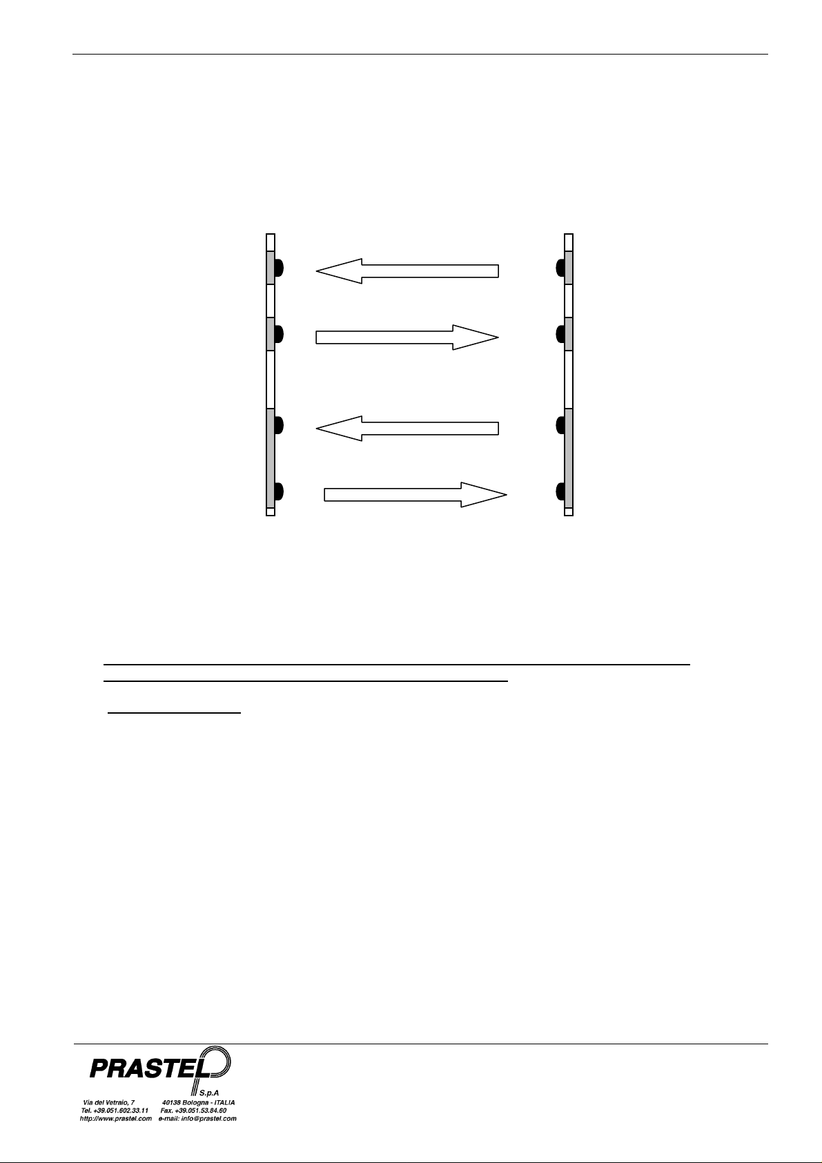
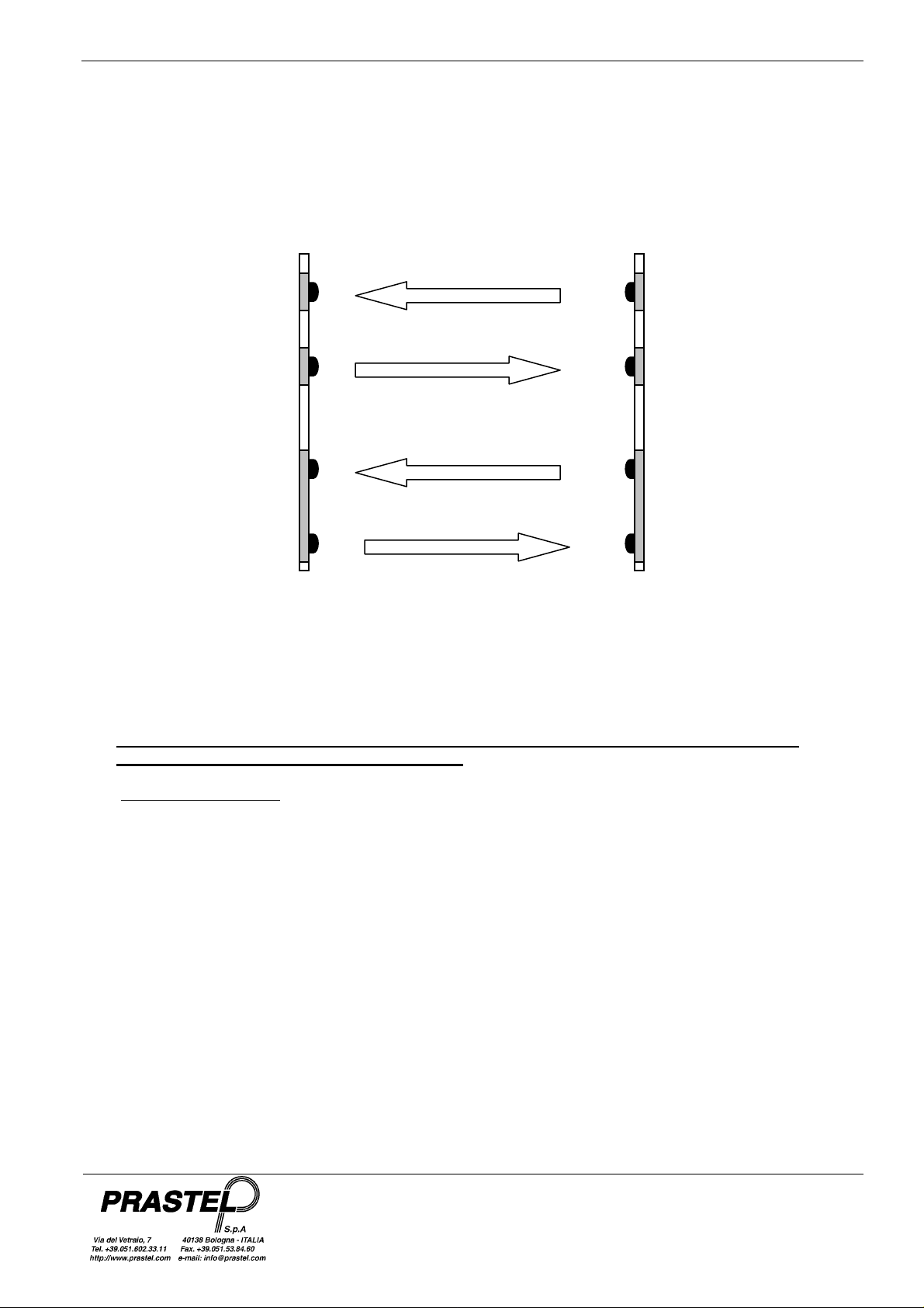
La barrière à infrarouges FSLIMPRO comprend une carte MASTER et une carte SLAVE incorporant le rayon 1,
et un rayon additionnel constitué d'une paire de sondes émetteur TX et récepteur RX.
Chaque rayon est constitué d'un faisceau à infrarouges aller et d'un faisceau à infrarouges retour; la carte
MASTER transmet le signal à la carte SLAVE qui, en cas de bonne réception, le retransmet à la carte MASTER,
se comportant ainsi comme un miroir “électronique”.
La barrière peut gérer jusqu'à quatre rayons (8 faisceaux au total); possibilité d'extension avec les rayons
individuels FSLIMPLUS disponibles en option.
5. MONTAGE DE LA BARRIERE FSLIMPRO
RX
TX
RX
TX
MASTER SLAVE
FRANÇAIS
TX
RX
TX
RX
ISFSLIMPRO_10_12_fra.doc
ATTENTION : SELON L’IMPLANTATION DES BARRIERES LE SOLEIL, PEUT CAUSER DES
PERTURBATIONS ET DECLENCHER DE FAUSSES ALARMES.
5.1 Préparation et fixation
1. Couper les profils en aluminium anodisé noir et le polycarbonate à la mesure désirée, si nécessaire.
2. Repérer les emplacements des perçages pour la fixation murale des profils, pour le passage du câble et
pour l'introduction de la protection antiarrachage, si nécessaire.
3. Percer avec un foret Ø 4 pour la fixation, avec un foret Ø 10,5 pour le passe-fil et avec un foret Ø 7,5 pour
la protection antiarrachage.
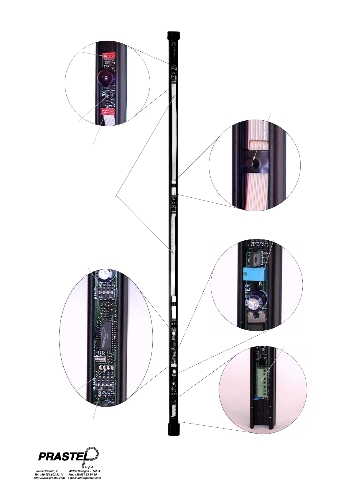
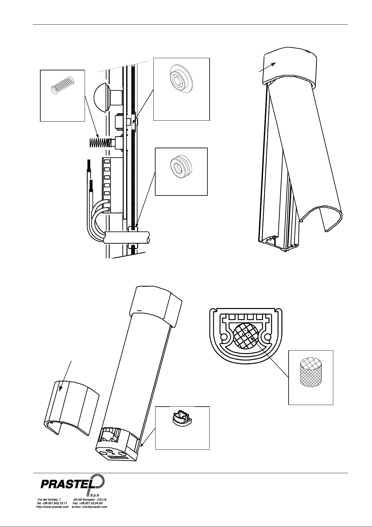
4. Poser les sondes émetteur TX et récepteur RX à l'intérieur des profils dans la position voulue et les fixer
avec la vis autotaraudeuse fournie (Fig. 1)
5. Dénuder le câble multipolaire d'alimentation et les contacts de protection et d'alarme.
6. Introduire le passe-fil dans le profil et faire passer le câble dans le passe-fil (Fig. 2).
7. Introduire le bouchon caoutchouc à l'extrémité supérieure du profil (Fig. 3).
8. Introduire l'éponge dans le bouchon plastique de façon à couvrir le trou d'évacuation de la condensation.
Enfiler le bouchon plastique dans le profil (Fig. 5).
9. Insérer les actionneurs en caoutchouc de la protection antiarrachage dans les trous prévus à cet effet et
insérer les ressorts sur les protections antiouverture (Fig. 2).
10. Fixer les profils au mur au moyen des vis de fixation et de leurs joints toriques.
11. Placer le câble plat des sondes dans le profil et le bloquer avec la griffe fournie (Fig. 1).
12. Relier les câbles d'alimentation et d'alarme comme indiqué ci-dessus et alimenter la barrière sous une
tension de 12Vcc. La barrière fonctionne alors avec les paramètres par défaut.
FSLIMPRO05 - 10 - 15 - 20 - 25
Leds rouges de
signalisation
alignement rayons
13. Vérifier l'alignement des rayons en contrôlant si les leds rouges qui se trouvent sur la carte MASTER et sur
la carte SLAVE sont éteintes ainsi que leur facilité d'interruption.
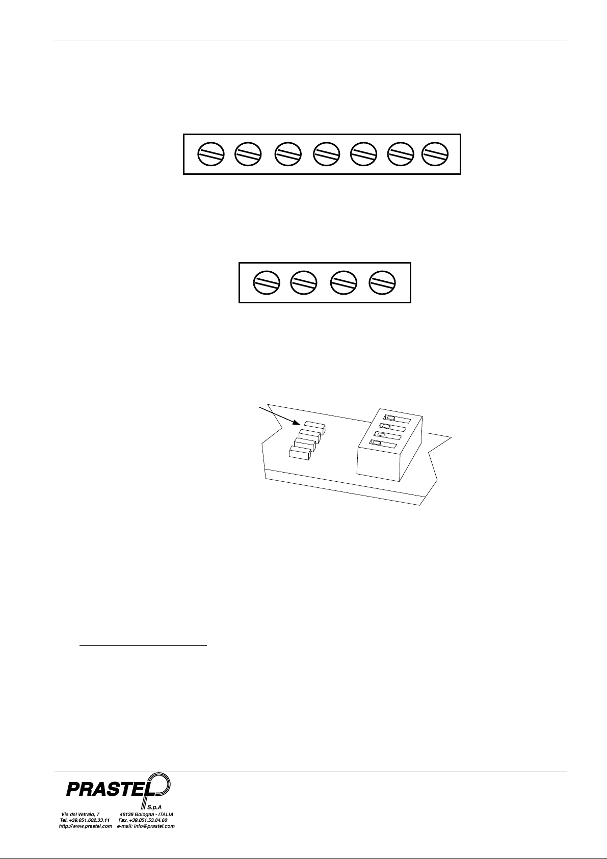
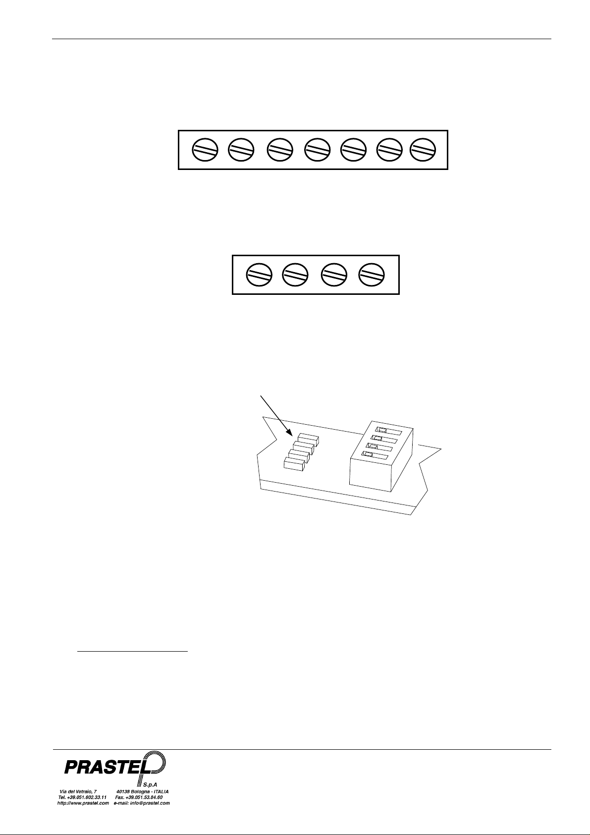
+12V GND NC C NO TAMPER
Bornier Master
Bornier Slave
+12V GND TAMPER
FRANÇAIS
ISFSLIMPRO_10_12_fra.doc
La led rouge sur la carte MASTER est allumée quand le rayon correspondant est désactivé ou bien qu'il est
interrompu ou désaligné soit sur le parcours MASTER vers SLAVE soit sur le parcours SLAVE vers MASTER.
La led rouge sur la carte SLAVE est allumée quand le rayon correspondant est désactivé ou bien qu'il est
interrompu ou désaligné sur le parcours MASTER vers SLAVE.
14. Monter le capot en polycarbonate comme l'indique la Fig. 3.
15. Monter le ressort en plastique, qui sert à recouvrir les éventuelles irrégularités dues à la coupe du profil, sur
le bouchon plastique Fig. 4.
16. Une fois l'installation terminée, recontrôler l'alignement des rayons.
5.2 Programmations et réglages
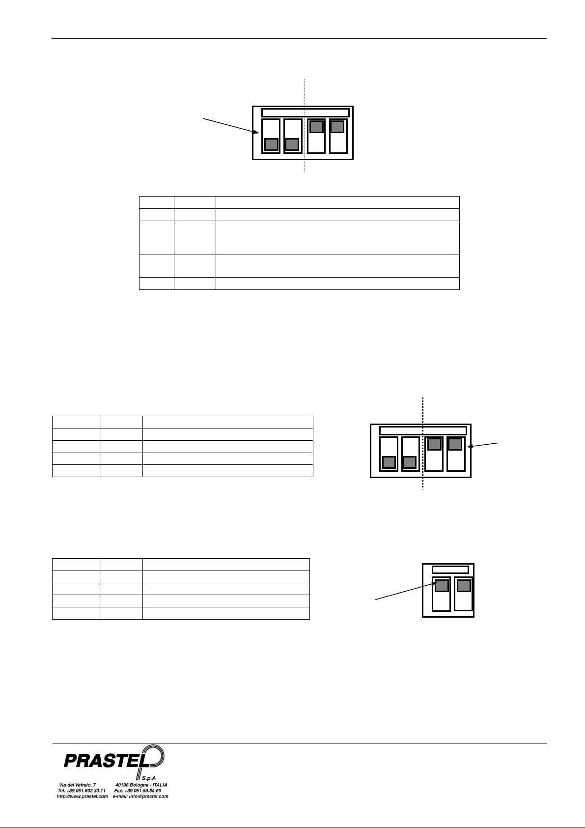
1. N'activer que les rayons connectés:
Sur les sondes TX et RX identifier le rayon (2,3,4) avec le cavalier à disposition en tenant compte du fait
que chaque rayon doit être composé d'un faisceau aller et d'un faisceau retour (voir par. 4).

FSLIMPRO05 - 10 - 15 - 20 - 25
portée
OFF
1 2 3 4
désactivé
FRANÇAIS
ISFSLIMPRO_10_12_fra.doc
Sélection du
rayon 2, 3 ou 4
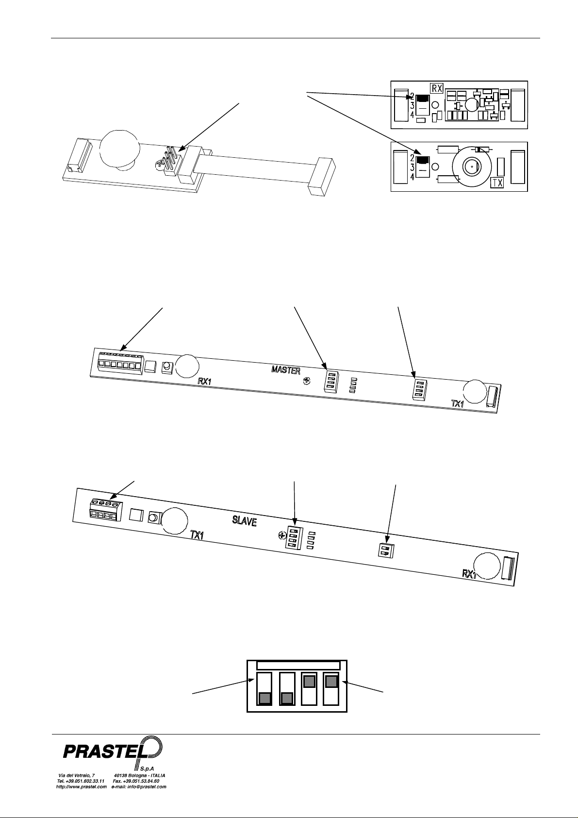
Sur les cartes MASTER et SLAVE mettre en position OFF les commutateurs DIP “RAGGI/BEAMS” des rayons
utilisés,
Bornier
MASTER
Sélection
rayons
Sélection alarme
et portée
FSLIMPRO - MASTER
Bornier
SLAVE
Sélection
Rayons
FSLIMPRO - SLAVE
Sélection
BEAMS/RAGGI
Rayon
Rayon
FSLIMPRO05 - 10 - 15 - 20 - 25
OFF
Activation
1 2 3 4
RANGE
OFF
ON
Portée
OFF
ON
1 2 3 4
FRANÇAIS
ISFSLIMPRO_10_12_fra.doc
2. Sélectionner le mode d'alarme désiré avec les commutateurs DIP “FUNCTION” 1 et 2 de la carte Master
Mode
Alarme
FUNCTION
ON
RANGE
Dip 1
OFF OFF
ON OFF
Dip 2 Activation alarme
Un rayon interrompu pendant au moins 0,1seconde
Au moins deux rayons adjacents interrompus pendant
200msec ou deux rayons non adjacents pendant
500msec
OFF ON
Au moins deux rayons adjacents interrompus pendant
200msec ou un rayon pendant 1 seconde
ON ON
Un rayon interrompu pendant au moins 1 seconde
3. Sélectionner l'intensité des rayons avec les commutateurs DIP “RANGE” 3 et 4 de la carte Master et avec
les commutateurs DIP “RANGE” 1 et 2 de la carte Slave selon la distance des profils et des conditions
ambiantes. En général, il faut effectuer la même sélection sur la carte MASTER et sur la carte SLAVE.
Master
Dip 3 Dip 4
ON ON
ON OFF
OFF ON
OFF OFF
Distance maxi profils interne/externe
10/6 mètres
7/4 mètres
4/2 mètres
2/1 mètres
FUNCTION
RANGE
Portée
rayons
Slave
Dip 1 Dip 2
ON ON
ON OFF
OFF ON
OFF OFF
Distance maxi profils interne/externe
10/6 mètres
7/4 mètres
4/2 mètres
2/1 mètres
rayons
FSLIMPRO05 - 10 - 15 - 20 - 25
Vis de fixation
de carte RX
Cavalier de sélection
sonde
Connecteur pour
les rayons
du câble plat
Vis de fixation de
Leds rouges de
Sélection alarme
et portée
suppleméntaires
du rayon
Câble plat de
connexion de la
FRANÇAIS
ISFSLIMPRO_10_12_fra.doc
Fig. 1
Ressort de serrage
Dip switch
signalisation
alignement
rayons
Sélection Rayons
l'amplificateur
Bornie
Dip switch
FSLIMPRO05 - 10 - 15 - 20 - 25
BOUCHON
CAOUTCHOUC
Fig. 2
FRANÇAIS
Fig. 3
ISFSLIMPRO_10_12_fra.doc
RESSORT
PROTECTION
Fig. 4
PROTECTION
ANTIARRACHAGE
PASSE-FIL
Fig. 5
BOUCHON
PLASTIQUE
CAPOT
BOUCHON
PLASTIQUE
EPONGE

FSLIMPRO05 - 10 - 15 - 20 - 25
1. INTRODUCTION
FSLIMPRO is especially designed and built for quick and easy installation. Installation is truly made easy
and wiring up is minimised (only the power supply cable and alarm contacts require wiring up) thanks to the
electronics incorporated in the sections and to the fact that there are no synchronism signals to be
transmitted by wire.
Sections are available in a number of lengths (from 1 to 2.5 m) so as to perfectly satisfy all protection
requirements. Fastening screws with appropriate O rings and specially shaped plugs guarantee perfect
section anchoring and seal, and durable outdoor installations.
Probe positioning to the desired height inside the FSLIMPRO so as to optimise barrier security as required is
easy and reliable thanks to the specially shaped aluminium sections and the fool-proof probe fastening
system.
2. MAIN FEATURES
• Sections in aluminium
• Top end plug in rubber and bottom end one in ABS with sponge pad protected aperture in the bottom for
air circulation against the risk of misting over because of condensate build-up inside the column and of
insects getting in and damaging the photocells.
• Cover in polycarbonate.
• Screws and O rings for secure wall anchoring.
• Equipped with four pairs of transmitter + receiver probes.
• Possibility of using up to 8 pairs of probes.
• Sliding on appropriate guide inside the Transmitter and Receiver probes and fastening by means of
screws.
• A tear-proof and anti-opening tamper on each column.
• Complete with cable routing bush hole for 6mm external diameter cable.
• Incorporated photocell amplifier with the following technical features:
multiplex and synchronised system;
management of up to 8 beams with 2 by 2 selection;
1 N.O./N.C exchange relay output.
• Easy installation and probe alignment thanks to four levels of intensity of the infra-red beams.
• Enabling of beams used by means of the four contact “BEAMS” Dip-Switch.
• Beam status indicator LED:
on = beam broken off or disabled
off = beam aligned or not broken off
• Operating mode selection via “FUNCTION” (1 and 2 ) Dip-Switch, as described in the following table:
Dip 1
OFF OFF
ON OFF
OFF ON
ON ON
3.
TECHNICAL SPECIFICATIONS
Power supply
Power consumption
Electric current requirement
I.R. wave length
Operating range
Relay outputs (clean exchange contact)
Relay response time
Reset time
Working temperature range
Dip 2
Beam broken off for at least 0.1seconds
At least two adjacent beams broken off for 200msec,
or two non-adjacent ones for 500msec
At least two adjacent beams broken off for 200msec,
One beam broken off for 1 second
ENGLISH
Alarm activation
or one beam for 1second
12Vdc
Max. 1.5 W
Max 50mA (4 pairs of enabled beams)
950 nm
10 metres indoors / 6 metres outdoors
N.O. / N.C
Minimum 100ms, maximum 1second
0.5 seconds
-20 °C to +55 °C
ISFSLIMPRO_10_12_uk.doc
FSLIMPRO05 - 10 - 15 - 20 - 25
BE
AM 1
BEAM 2
4.
OPERATING PRINCIPLE
The FSLIMPRO infra-red beam barrier comprises a MASTER and a SLAVE card with beam 1 on-board, and an
additional beam made up of a pair of TX transmitter and RX receiver probes.
Each beam consists of a pair of signals, one outgoing the other incoming. The former is transmitted by the
MASTER card to the Slave card that upon correctly receiving the signal relays it back to the MASTER card, thus
practically acting like an “electronic” mirror.
The barrier is capable of managing up to four pairs of beams (8 beams overall). Single beam expansions are
available on request (use code FSLIMPLUS when ordering).
5 INSTALLING FSLIMPRO
WARNING : ACCORDING TO BARRIERS INSTALLATION LOCATION, THE SUN MAY CREATE
DISRUPTIONS AND TRIGGER FALSE-ALARMS.
5.1 Mounting and wiring up
1. If necessary, cut the black anodised sections and the polycarbonate to the desired lengths and sizes.
2. Identify points where to drill the holes for fastening the sections to the wall, for wire routing, and for inserting
the tear-proof tamper if necessary.
3. Use a Ø 4 bit to drill the fastening holes, a Ø 10.5 one for the wire routing hole, and a Ø 7.5 one for the tear-
proof tamper hole.
4. Position the TX Transmitter and RX Receiver probes inside the sections as desired and fasten into place by
means of the self-threading screws provided (see Figure 1).
5. Strip the multi-pole power cable and the tamper and alarm contacts.
6. Insert the wire routing bush hole onto the section and route in the cable (see Figure 2).
7. Insert the rubber plug at the top end of the section (see Figure 3).
8. Fit the sponge pad inside the plastic plug so as to cover the condensate drain hole. Insert the plastic plug
inside the section (see Figure 5).
9. Insert the rubber tear-proof tamper actuators into the appropriate holes and fit the clips onto the anti-
opening tampers (see Figure 2).
10. Secure the sections to the wall by means of the fastening screws and relevant O rings.
11. Fit the flat probe cable into the section and fasten down with the clip provided (see Figure 1).
12. Wire up power and alarm connections as shown below and power the barrier with 12 Vdc. The barrier is
now fully operative with all due default settings.
RX
TX
RX
TX
MASTER
ENGLISH
TX
RX
TX
RX
SLAVE
ISFSLIMPRO_10_12_uk.doc
FSLIMPRO05 - 10 - 15 - 20 - 25
Red LEDs indicating
proper beam
)
13. Check that MASTER and SLAVE red LEDS go off indicating proper beam alignment and also check for
easy beam break off.
+12V GND NC C NO TAMPER
Master Term. Strip
Slave Term. Strip
+12V GND TAMPER
ENGLISH
ISFSLIMPRO_10_12_uk.doc
alignment (when off
The MASTER red LED comes on when the corresponding beam is disabled, or broken off or not properly
aligned in the MASTER to SLAVE or SLAVE to MASTER stretch.
The SLAVE red LED comes on when the corresponding beam is disabled, or broken off or not properly aligned
in the MASTER to SLAVE stretch.
14. Fit on the polycarbonate cover as shown in Figure 3.
15. Fit the plastic clip on to the plastic plug to cover up any roughly cut edges as shown in Figure 4.
16. Make a last check of the installation and a final alignment of the beams.
5.2 Settings and adjustments
1. Only enable connected beams:
identify connected beams (2,3,4) in the TX and RX probes by means of the jumper, bearing in mind that
beams come in pairs as they consist of an outgoing and an incoming probe (see par. 4).
FSLIMPRO05 - 10 - 15 - 20 - 25
selection
ON
OFF
Beam
enabled
1 2 3 4
Beam 2, 3 or 4
Selection
ENGLISH
ISFSLIMPRO_10_12_uk.doc
In the MASTER and SLAVE boards set in OFF position the “BEAM” DIP SWITCHES referred to the used
beams.
MASTER
Terminal strip
beam
selection
alarm and range
selection
FSLIMPRO - MASTER
SLAVE
Terminal strip
beam
range
selecti
on
FSLIMPRO - SLAVE
BEAMS
Beam
disabled
 Loading...