

Prastel FOTO9S2A User Manual

FOTO9S2A
ITALIANO
ISFT9S2AEU_04_02.doc
FOTO9S2AST
1. DESCRIZIONE GENERALE
L’amplificatore fotocellula a 2 raggi
FOTOSLIM
etc..) garantisce la massima sicurezza in un accesso automatizzato; Es: ascensori, bussole antirapina,
FOTO9S2A
porte automatiche, basculanti industriali, etc.. Può essere utilizzato sia posizionando le sonde direttamente sul varco,
che all’interno di una o più coste di sicurezza. Conforme agli standard Europei di riferimento (Compatibilità
Elettromagnetica 89/336/CEE), è costruito con “Elettronica Ridondante”. Il
versione con box per uso esterno IP56 dotato di passacavi (mod.
L‘amplificatore dispone di:
Un Dip-Switch
•
Due LED rossi per la segnalazione dello stato dei raggi
•
a due contatti per l‘abilitazione dei singoli raggi (posizione ON della levetta),
SW1
LED acceso = raggio interrotto o disabilitato / LED spento = raggio allineato e non interrotto
Un potenziometro TR1 di regolazione dell’attenuazione dei raggi
•
cursore tutto a destra = minima portata / cursore tutto a sinistra = massima portata
Si riporta di seguito una tabella con l‘indicazione della portata massima di una sonda
posizione del cursore del Trimmer TR1.
Posizione Cursore Trimmer TR1 Portata CR9MS [mt]
Finecorsa verso antiorario 9
7/8 7.5
6/8 6
5/8 5
4/8 4
3/8 3
2/8 2.5
1/8 2
Finecorsa verso orario 1.5
Un’uscita attivata quando uno dei due raggi è interrotto.
•
UN LED verde che segnala lo stato dell’uscita (LED acceso = Uscita non attiva, LED spento = uscita attiva)
•
Un pulsante di TEST per la verifica del corretto funzionamento dell‘amplificatore. Se i raggi sono allineati (led rossi
•
spenti) premendo il pulsante si disabilita la trasmissione del treno di impulsi sui singoli raggi, pertanto se
l‘amplificatore funziona correttamente avverrà l‘accensione dei led rossi per tutto il tempo per cui il pulsante è
tenuto premuto.
Un ingresso di Test in morsettiera. Se il
•
70msec segnala il suo corretto funzionamento attivando l’uscita.
2. CARATTERISTICHE PRINCIPALI
Sistema multiplexato e sincronizzato per un’alta immunità ai disturbi
•
Elettronica ridondante
•
Gestione di 2 raggi
•
1 uscita a relè in scambio N.O./N.C. corrispondente all’interruzione di uno dei due raggi, con tempo d’intervento di
•
50 msec
Facilità d’installazione e d’allinemento delle sonde grazie alla funzione di “Attenuazione Intensità” dei raggi infrarossi
•
mediante trimmer.
Abbinabile alle sonde Prastel modelli:
•
Conforme alle Direttive Europee di riferimento:
•
CR9MS, CR9MS9, CR9MSD, CR9MSP, CRFC, CR20MS, FOTOSLIM.
3. CARATTERISTICHE TECNICHE
Alimentazione
Potenza assorbita
Corrente Assorbita
Lunghezza d’onda I.R.
Portata
Uscite a relè (contatto pulito in scambio)
Tempo d’intervento del relè
Tempo di ripristino
Temperatura di Funzionamento
Dimensioni
Peso
Il dispositivo FOTO9S2 A deve essere installato all’int ern o di un al tro in volu cro c he presenti un grado IP almeno pari a IPX4. Q uesto involucro deve
essere accessibil e media nt e ut en sili.
La fotocellula è un dispositi vo a usil i ar io di ril e vame nt o persone e/o oggetti e deve essere ut ilizz at a con gi unta m ent e ad un dis positivo di sicurezza.
La fotocellula deve essere sottoposta a controlli con periodicità non superiore ai 6 mesi.
in abbinamento alle apposite sonde (
FOTO9S2A
FOTO9S2AST
).
CR9MS, CR9MSD, CR20MS
è disponibile anche nella
CR9MS
FOTO9S2A
riceve sull‘ingresso di TEST un impulso della durata minima di
Compatibilità Elettromagnetica (EMC) 89/336/CEE
12÷24 Vac/dc ± 10%
Max. 1 W a 12Vac Max.1,5 W a 24Vac
Max 60mA (2 raggi abilitati)
850 nm
0,1 ÷ 20 m nominali (dipendente dalle sonde impiegate).
N.A. / N.C.
50 ms
0,5 s
-20 °C ÷ +55 °C
110 X 75 X 35 mm
400 g
FOTO9S2A,
FOTO9S2A,
500 g
110 X 55 X 75 mm
FOTO9S2AST
in funzione della
FOTO9S2AST
,
1

FOTO9S2A
A
S
R
ITALIANO
FOTO9S2AST
4. COLLEGAMENTO E MESSA IN FUNZIONE DELLA CENTRALINA
Prima di eseguire l’installazione dell’amplificatore fotocellula
sicurezza”.
•
Fissare il box tramite gli appositi fori di fissaggio
•
Allineare le sonde
•
Fare passare i cavi di collegamento nelle apposite asole nella versione
versione
•
Collegare i cavi di alimentazione e di segnale.
FOTO9S2AST
.
La distanza massima di collegamento fra elettronica e sonde è di 20 metri.
N.B.: per il collegamento delle sonde trasmettitore è necessario collegare il cavetto centrale (filo rosso) sul morsetto
comune TX e le calze sui morsetti 1 o 2.
Per il collegamento delle sonde ricevitore è necessario invece collegare la calza sul morsetto comune RX e il
cavetto c entrale (fil o bianco) sui morsetti 1 o 2.
•
Abilitare i raggi utilizzati mediante il Dip-Switch
(ON = raggio abilitato, OFF = raggio disabilitato)
•
Alimentare e verificare che il LED Rosso associato ad ogni raggio abilitato sia spento. Se ciò non accade
provvedere ad allineare le sonde.
•
Premere il pulsante di “Test” per la verifica del corretto funzionamento dell‘amplificatore. In questo modo cessa la
trasmissione degli impulsi sui raggi abilitati, il LED Rosso corrispondente deve accendersi, ed il LED Verde
dell’uscita utilizzata deve spegnersi.
•
Per verificare la bontà dell’allineamento delle sonde, ruotare il Trimmer in senso orario (riduzione della portata delle
sonde) fino a che si accende un LED rosso (raggio disallineato), ruotare poi il Trimmer in senso antiorario di ¼ di
giro per garantirsi un adeguato margine di sicurezza al variare delle condizioni ambientali.
CHEMA DI COLLEGAMENTO FOTO9S2A
SW1
FOTO9S2A
ISFT9S2AEU_04_02.doc
leggere le “Avvertenze generali per la
FOTO9S2A
, o negli appositi passacavi nella
PULSANTE
DI TEST
REGOLAZIONE
ATTENUAZIONE
+ - + ~ ~ TEST
12/24Vac
TX1 TX2
X1 RX2
BILITAZIONE RAGGI
2
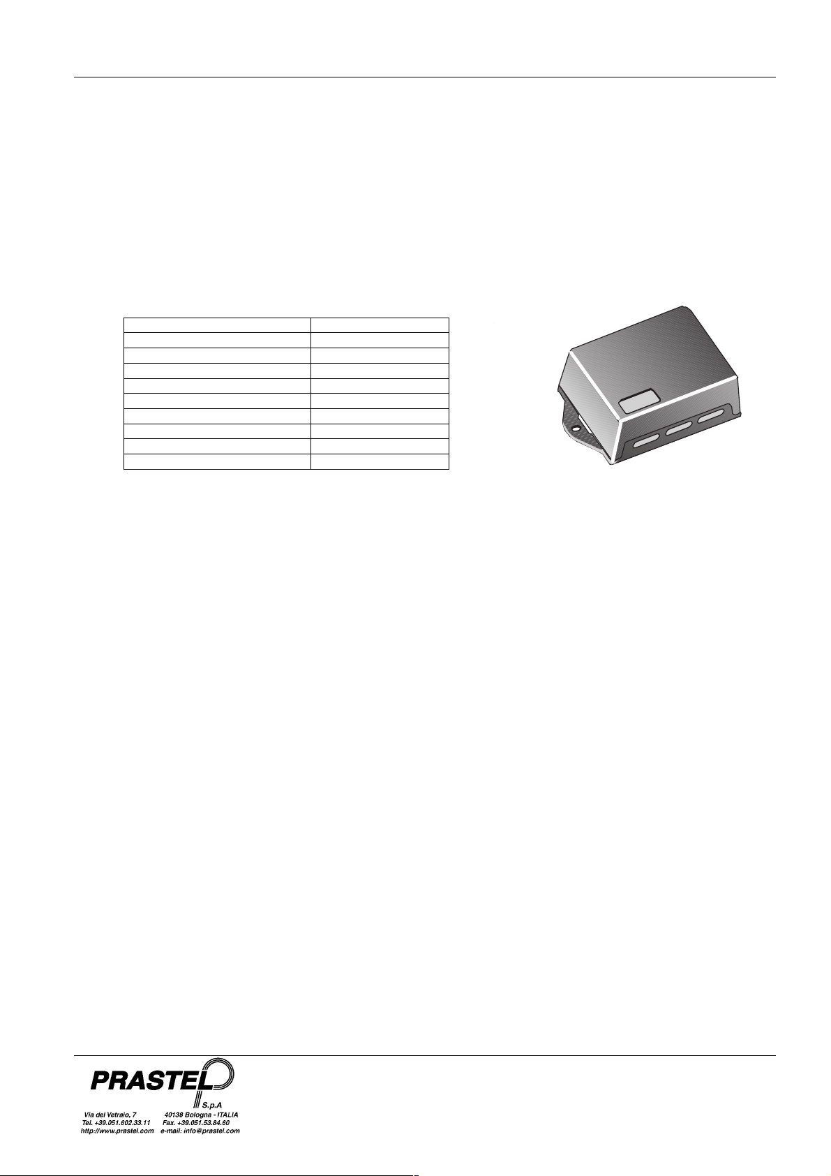
FOTO9S2A
ENGLISH
ISFT9S2AEU_04_02.doc
FOTO9S2AST
1. GENERAL DESCRIPTION
The 2 beam photocell amplifier
FOTO9S2A
together with the special probes (
ensures maximum safety in automated access, e.g. lifts, robber-proof revolving doors, automatic doors, industrial
counterweighted doors etc… It can be used either positioning the probes directly on the opening or inside one or more
safety ribs. It conforms with the European reference standards (Electromagnetic compatibility 89/336/CEE) and is built
with “Redundant Electronics. The
cable conduits (mod.
FOTO9S2AST
FOTO9S2A
).
is also available in a box version for external use IP56 equipped with
The amplifier has:
•
•
SW1
An
two contact Dip-Switch for enabling the individual beams (lever position ON),
Two red LEDs indicating the beam state
LED on = beam interrupted or disabled / LED off = beam aligned and uninterrupted
•
A TR1 potentiometer for adjusting beam attenuation
cursor completely to the right = minimum capacity / cursor completely to the left = maximum capacity
The table below shows the maximum capacity of a
CR9MS
probe in function of TR1 Trimmer cursor position.
TR1 Trimmer Cursor Position Capacity CR/9MS [mt]
Anticlockwise end of stroke 9
7/8 7.5
6/8 6
5/8 5
4/8 4
3/8 3
2/8 2.5
1/8 2
Clockwise end of stroke 1.5
•
An output activated when one of the beams is interrupted.
•
A green LED indicating the state of the output (LED on = Exit not active, LED off = exit active)
•
A TEST button to check correct amplifier functioning. If the beams are aligned (red LEDs off), by pressing the button
the transmission train of impulses on the individual beams is disabled, so if the amplifier is working correctly the red
LEDs will remain lit for the whole time the button is held down.
•
A Test input on the terminal board. If the
FOTO9S2A
receives, on the TEST input, an impulse of a minimum
duration of 70msec it signals correct functioning by activating the output.
2. MAIN FEATURES
•
Multiplex synchronised system for high immunity to disturbance
•
Redundant electronics
•
Management of 2 beams
•
1 relay output in N.O. / N.C. exchange corresponding to interruption of one of the two beams with an intervention
time of 50msec
•
Easy installation and alignment of the probes, thanks to the “Intensity Attenuation” of infrared rays function by means
of a trimmer.
•
Can be coupled with the Prastel probe models:
•
Conformity with reference European Directives:
CR9MS, CR9MS9, CR9MSD, CR9MSP, CRFC, CR20MS.
Electromagnetic Compatibility (EMC) 89/336/CEE
3. TECHNICAL CHARACTERISTICS
Supply
Power absorbed
Current absorbed
I.R wavelength.
Range
Relay outputs (contact clean in exchange)
Relay intervention time
Reset time
Working temperature
Size
Weight
The FOTO9S2A device must be installed inside another casing that features an IP rating of at least X4. The inside of the casing mus t be ac ce ssible
by means of appropriate tools.
The photocell is an auxil iary device for the detecti o n of per s o ns an d/ or obje ct s an d mu st th er ef or e be use d in conj un ction with a security devi ce.
The photocell mus t be su bjected to periodical checks at least once e very 6 months.
12÷24 Vac/dc ± 10%
Max. 1 W a 12Vac Max.1.5W a 24Vac
Max 60mA (2 beams enabled)
850 nm
0,1 ÷ 20 m nominal (depending on probes used).
N.A. / N.C.
50 ms
0,5 s
-20 °C ÷ +55 °C
110 X 75 X 35 mm
FOTO9S2A,
400 g
FOTO9S2A,
FOTO9S2AST
500 g
CR9MS, CR9MSD, CR20MS
110 X 55 X 75 mm
FOTO9S2A
FOTO9S2AST
, etc..)
3
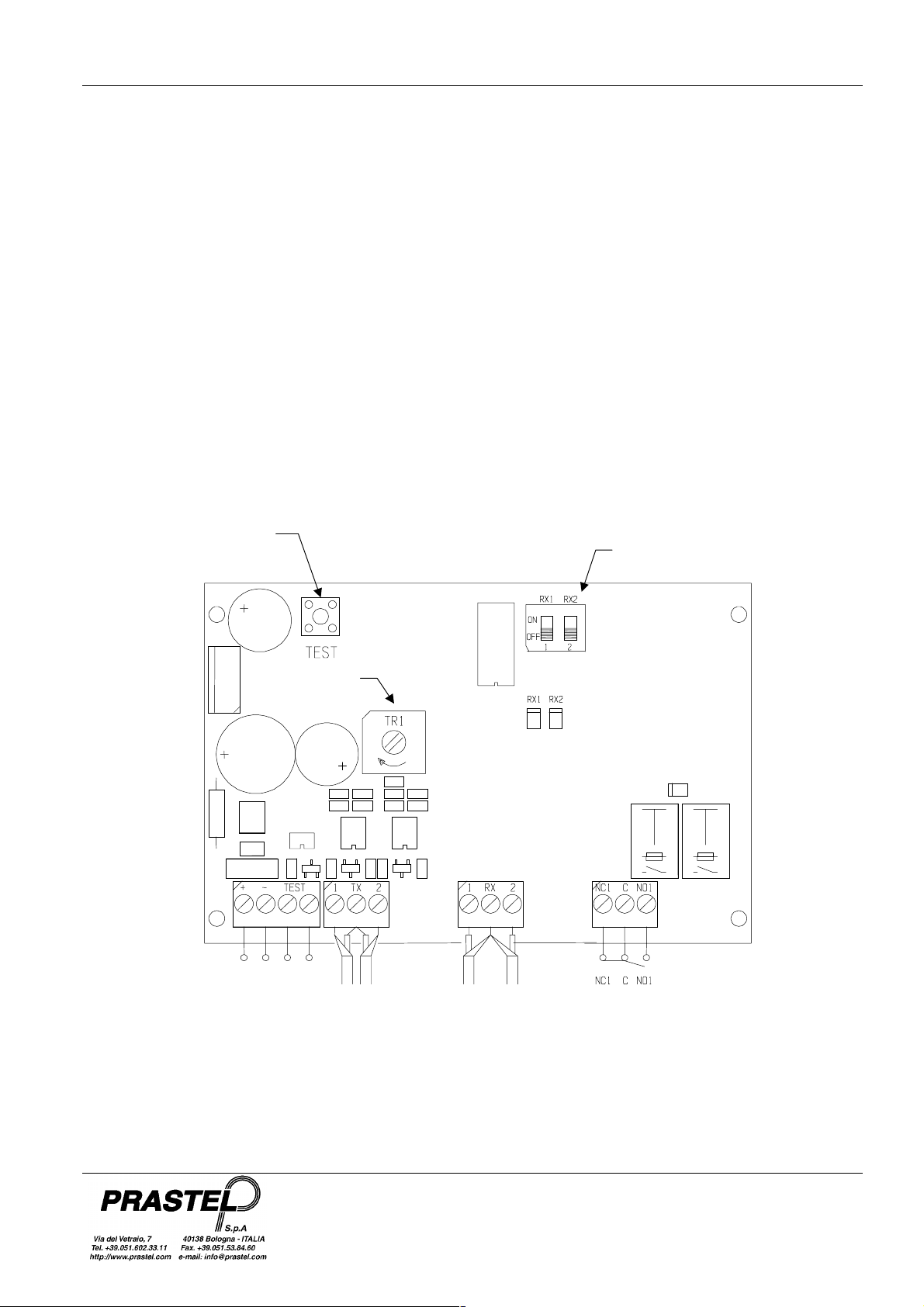
FOTO9S2A
B
F
R
FOTO9S2AST
4. TRIGGER BOX CONNECTION AND START-UP
Before installing the
•
Fix the box by means of the special fixing holes.
•
Align the probes
•
Pass the connection cables through the special slots in the
FOTO9S2AST
•
Connect the power supply and signal cables. The maximum connection distance between electronics and probes is
20 metres.
N.B.: For connection of the transmitter probes you must connect the central cable (red wire) to the common terminal
TX and the braided wire to terminals 1 or 2. For connection of the receiver probes you must connect the braided wire
to the common terminal RX and the central cable (white wire) to terminals 1 or 2.
•
Enable the beams utilised by means of the Dip-Switch SW1 (ON = beam enabled, OFF = beam disabled)
•
Power up and check that the Red LED associated with each enabled beam is off. If this is not the case, align the
probes.
•
Press the “Test” button to verify correct functioning of the amplifier. In this way impulse transmission on the enabled
beams ceases. The corresponding Red LED must light up and the Green LED of the output used must go out.
•
To verify the efficiency of the probe alignment, turn the Trimmer clockwise (reduction of probe range) until a red LED
comes on (beam unaligned), then turn the Trimmer a quarter turn anticlockwise to ensure an adequate safety
margin for variations in environmental c onditions.
FOTO9S2A
version.
photocell amplifier read the “General safety warnings ”.
OTO9S2A CONNECTION DIAGRAM
ENGLISH
FOTO9S2A
ISFT9S2AEU_04_02.doc
version, or the special cable conduits in the
TEST
BUTTON
ATTENUATION
ADJUSTMENT
+ - + ~ ~ TEST
12/24Vac
TX1 TX2
X1 RX2
EAM ENABLING
4
 Loading...