

Prastel FOTO35SDE User Manual
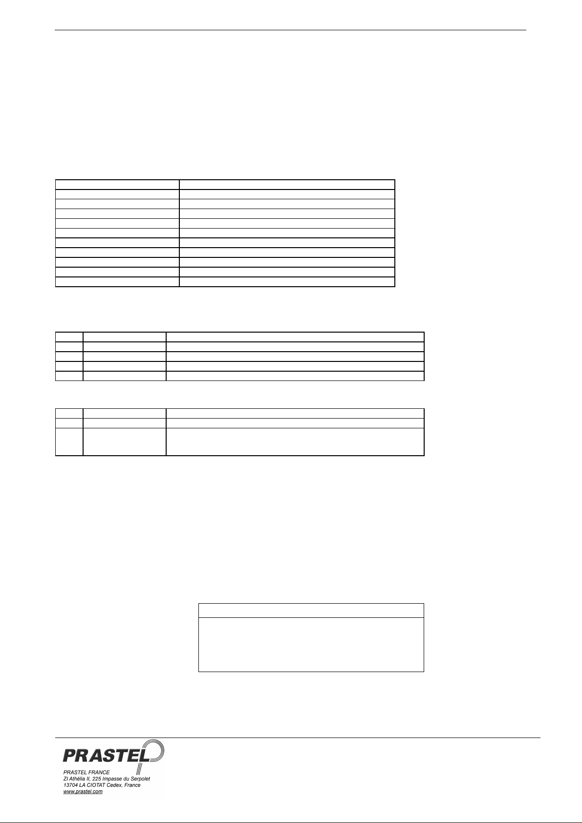
FOTO35SDE
1. DESCRIPTION GÉNÉRALE
La cellule photoélectrique FOTO35SDE a été conçue et réalisée pour l’utilisation sur les portails motorisés (portes, portails, ...). Elle est
équipée d’une fonction d'autotest, utilisable en combinaison à des centrales capables de la gérer (par exemple EURO1MF ou
EURO2MF).
La fonction d’autotest est exécutée de la façon suivante : la centrale inhibe le transmetteur, avant toutes manœuvres, en envoyant une
tension comprise entre +5 et +24 VDC sur la borne n° 3. L’absence du faisceau infrarouge, causé de cette façon, génère, avec un
retard de 20 ms, l’ouverture du contact N.C. sur le récepteur. La centrale vérifie si la procédure décrite a été correctement exécutée
avant toute manœuvre.
Le produit est conforme à la directive Européenne sur la compatibilité électromagnétique (89/336/CEE).
2. APPLICATIONS
En combinaison aux centrales dotées de dispositif d’autotest pour applications de sécurité.
3. CARACTÉRISTIQUES TECHNIQUES PRINCIPALES
Alimentation (TX - RX) 12 ÷ 24 V AC/DC
Consommation 30 mA (TX) ÷ 25 mA (RX)
Boîtier Nylon renforcé avec fibre de verre
Dimensions/poids Fig. 1/ 400 g.
Fréquence de modulation 1000 Hz
Degré d’isolation IP 44
Longueur d’onde infrarouge 950 nm
Capacité contact relais 0,5 A @ 24 VAC/DC
Portée faisceau infrarouge 35m (FOTO35SDE) nominaux (*)
Température de fonctionnement -20 + 60° C
Temps d’intervention < 20ms
(*) Cette valeur peut être réduite jusqu’à 70 % en présence de phénomènes atmosphériques d’intensité importante, ou à cause d’un
alignement non précis.
4. BOITE A BORNES RÉCEPTEURS
1 +12 / +24 VAC/DC Alimentation 12 - 24 VAC/DC
2 0 V Commun d’alimentation
3 N.C. Contact normalement fermé relais
4 C Commun contact relais
5 N.A. Contact normalement ouvert relais
5. BOITE A BORNES ÉMETTEUR
1 +12 / +24 VAC/DC Alimentation 12 - 24 VAC/DC
2 0 V Commun d’alimentation
3 Entrée autotest
6. FONCTIONNEMENT
Effectuer l’alignement du faisceau au récepteur en agissant sur les vis de réglage « A » (fig. 2) prévues à cet effet présentes aussi bien sur
le récepteur que sur l’émetteur. L’interruption du faisceau infrarouge génère l’ouverture du contact normalement fermé du relais sur le
récepteur.
7. REMARQUES
La vérification de l’alignement se fait en mesurant avec un voltmètre la valeur de tension présente sur le test-point du récepteur (P- / P+ fig.
3). Cette valeur varie en fonction de différents paramètres comme la distance entre les cellules photoélectriques, l’alignement … et peut
prendre des valeurs comprises entre 0V et 5 VDC.
Les valeurs en-dessous de 1.5VDC correspondent à un mauvais alignement du rayon.
De +5 à +24 VDC pour bloc émission faisceau infrarouge
Ne pas utiliser la borne 3 si la centrale n'est pas en mesure de
gérer la fonction d'AUTOTEST.
FRANÇAIS
ISF35SDEEU_03_13.DOC
Distance TX-RX Valeur sur T.P.
5 m 2.5 – 3.0 VDC
10 m 2.2 – 2.7 VDC
20 m 2.0 – 2.4 VDC
30 m 1.5 – 2.0 VDC
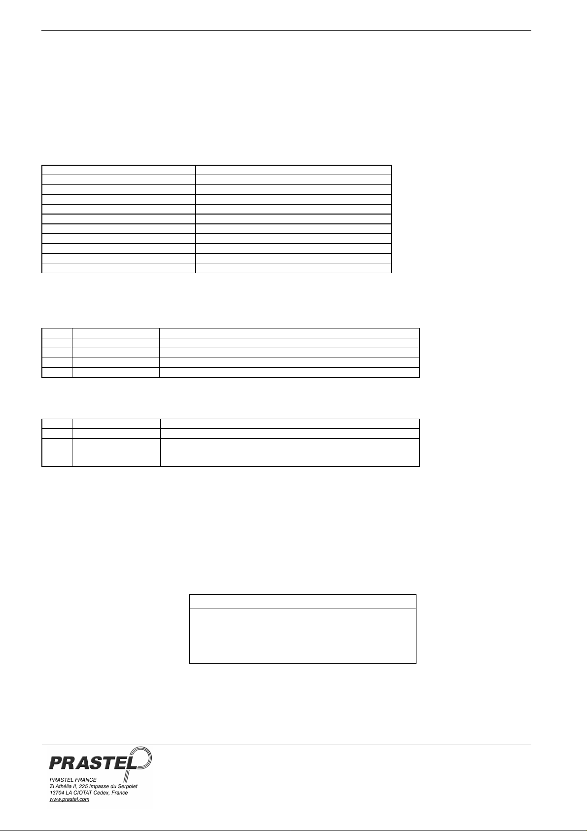
FOTO35SDE
1. GENERAL DESCRIPTION
The photocell FOTO35SDE has been designed and created for use on power operated doors (gates, doors,..). It has autotest function,
usable with control units able to manage it (e.g. EURO1MF or EURO2MF). The autotest function is carried out as follows: before any
manoeuvre the station inhibits the transmitter by sending a voltage between +5 and +24 VDC on terminal N° 3. The absence of the
infrared beam thus brought about generates, with a 20 ms. delay, opening of the receiver’s N.C. contact. The station checks that the
described procedure is properly carried out before each manoeuvre. It complies with European directive 98/336/EEC (EMC).
2. APPLICATIONS
With stations equipped with autotest device for safety applications.
3. MAIN TECHNICAL FEATURES
Power supply (TX - RX) 12 ÷ 24 VAC/DC
Consumption 30 mA (TX) ÷ 25 mA (RX)
Container Fiber glass added nylon
Size / Weight Fig. 1/400 g.
modulation frequency 1000 Hz
Degree of insulation IP 44
Infrared wavelength 950 nm
Relay contact capacity 0,5 A @ 24 VAC/DC
Infrared beam range 35m (FOTO35SDE) nominal (*)
Working temperature -20 +60° C
Intervention time < 20ms
(*) This value can decrease to 70 % owing to very violent atmospheric phenomena or to inaccurate alignment.
4. RECEIVER TERMINAL BOARD
1 +12 / +24 VAC/DC
2 0 V Common supply
3 N.C. Relay contact normally closed
4 C Common relay contact
5 N.A. Relay contact normally open
5. TRANSMITTER TERMINAL BOARD
1 +12 / +24 VAC/DC
2 0 V Common supply
3 Autotest input
6. FUNCTIONING
Align the beam with the receiver using the screws “A” (fig. 2) on the receiver and transmitter. Interruption of the infrared beam
generates opening of the normally closed contact of the relay on the receiver.
7. NOTES
Alignment is checked by measuring the voltage value at the receiver test-points (P- / P+ fig.3). This value varies in accordance with various
parameters, among which the distance between the photocells, and can range between 0 and 5 VDC.
Values below 1.5 VDC correspond to bad beam alignment.
Power supply 12 - 24 VAC/DC
Power supply 12 - 24 VAC/DC
From +5 to +24 VDC to block infrared beam emission
Do not use terminal 3 if the control unit is not able to manage
the AUTOTEST function.
ENGLISH
ISF35SDEEU_03_13.DOC
Distance TX-RX Value on T.P.
5 m 2.5 – 3.0 VDC
10 m 2.2 – 2.7 VDC
20 m 2.0 – 2.4 VDC
30 m 1.5 – 2.0 VDC
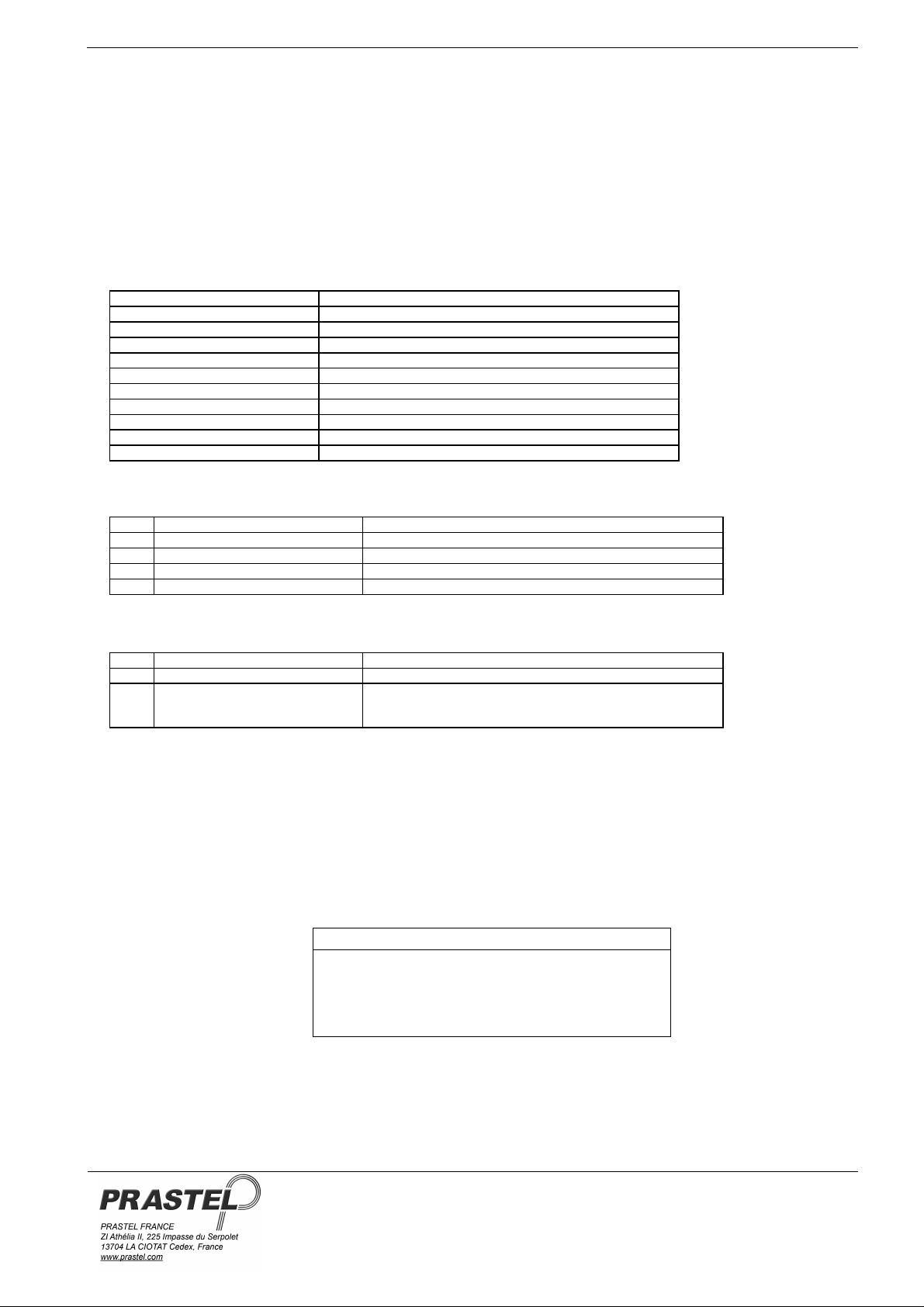
FOTO35SDE
1. DESCRIZIONE GENERALE
La fotocellula FOTO35SDE è stata progettata e realizzata per l’utilizzo su accessi automatizzati (cancelli, porte, serrande, etc).
Dispone della funzione di autotest, utilizzabile in abbinamento a centrali in grado di gestirla (EURO1MF, EURO2MF...).
La funzione di autotest è eseguita nel modo seguente: la centrale inibisce il trasmettitore, prima di ogni manovra inviando una tensione
compresa tra +5 e +24 VDC sul morsetto Nr.3. L’assenza del fascio infrarosso, in tal modo causato, genera, con un ritardo di 20 ms,
l’apertura del contatto N.C. sul ricevitore. La centrale verifica che la procedura descritta sia correttamente eseguita prima di ogni
manovra.
Conforme agli standard Europei di riferimento (Compatibilità Elettromagnetica 89/336/CEE).
2. APPLICAZIONI
In abbinamento a centrali dotate di dispositivo di autotest per applicazioni di sicurezza.
3. CARATTERISTICHE TECNICHE PRINCIPALI
Alimentazione (TX - RX) 12 ÷ 24 VAC/DC
Consumo 30mA (TX) ÷ 25 ma (RX)
Contenitore Nylon caricato a vetro
Dimensioni Fig. 1/ 400 g.
Frequenza di modulazione 1000 Hz
Grado d'isolamento IP 44
Lunghezza d’onda infrarosso 950 nm
Portata contatto relè 0,5 A @ 24 VAC/DC
Portata fascio infrarosso 35m (FOTO35SDE) nominali (*)
Temperatura di funzionamento -20 + 60° C
Tempo d’intervento < 20ms
(*) Questo valore si può ridurre fino al 70 % in presenza di fenomeni atmosferici di notevole intensità o per un allineamento non curato
4. MORSETTIERA RICEVITORE
1 +12 / +24 VAC/DC
2 0 V Comune d’alimentazione
3 N.C. Contatto normalmente chiuso relè
4 C Comune contatto relè
5 N.A. Contatto normalmente aperto relè
5. MORSETTIERA TRASMETTITORE
1 +12 / +24 VAC/DC
2 0 V Comune d’alimentazione
3 Ingresso autotest
6. FUNZIONAMENTO
Effettuare l’allineamento del fascio al ricevitore agendo sulle apposite viti “A” (fig. 2) fornite in dotazione sia sul ricevitore, che sul
trasmettitore. L’interruzione del fascio infrarosso genera l’apertura del contatto normalmente chiuso del relè sul ricevitore
7. NOTE
La verifica dell’allineamento si effettua misurando con un voltmetro il valore di tensione presente sul test-point del ricevitore (P- / P + fig. 2).
Tale valore varia in funzione di vari parametri tra cui la distanza tra le fotocellule e può assumere valori compresi tra 0 e 5 VDC.
Valori inferiori a 1.5 VDC indicano in ogni caso un cattivo allineamento.
Alimentazione 12 - 24 VAC/DC
Alimentazione 12 - 24 VAC/DC
Da +5 a +24 VDC per blocco emissione fascio infrarosso
Non utilizzare il morsetto 3 se la centrale non è in grado di
gestire la funzione AUTOTEST
ITALIANO
ISF35SDEEU_03_13.DOC
Distanza TX-RX Valore su T.P.
5 m 2.5 – 3.0 VDC
10 m 2.2 – 2.7 VDC
20 m 2.0 – 2.4 VDC
30 m 1.5 – 2.0 VDC
 Loading...