

Prastel EasyPL User Manual
EASYPL
ENGLISH
ISEASYPL_04_08.doc
1. INTRODUCTION
The EASYPL is a keypad access control unit suitable for external
applications. The unit accepts up to 500 users and provides entry via
the use of PIN codes.
2. MAIN TECHNICAL FEATURES
Operating Voltage Range: 12-24 VAC/DC
Maximum Input Current: 75 mA in standby -- 135 mA max
Lock Strike Relay: Form C, 5A
Auxiliary Relay: Form C, 5A
Inputs:
REX N.O., Dry Contact
Auxiliary Input (In / Monitor) N.C., Dry Contact in Monitor Mode
N.O., Dry Contact in Input Mode
Operating Temperature: 0 °C to 63 °C
IP protection degree: IP 65
Dimensions: 137mm x 44mm x 29mm
Weight: 178 g
1
EASYPL
ENGLISH
ISEASYPL_04_08.doc
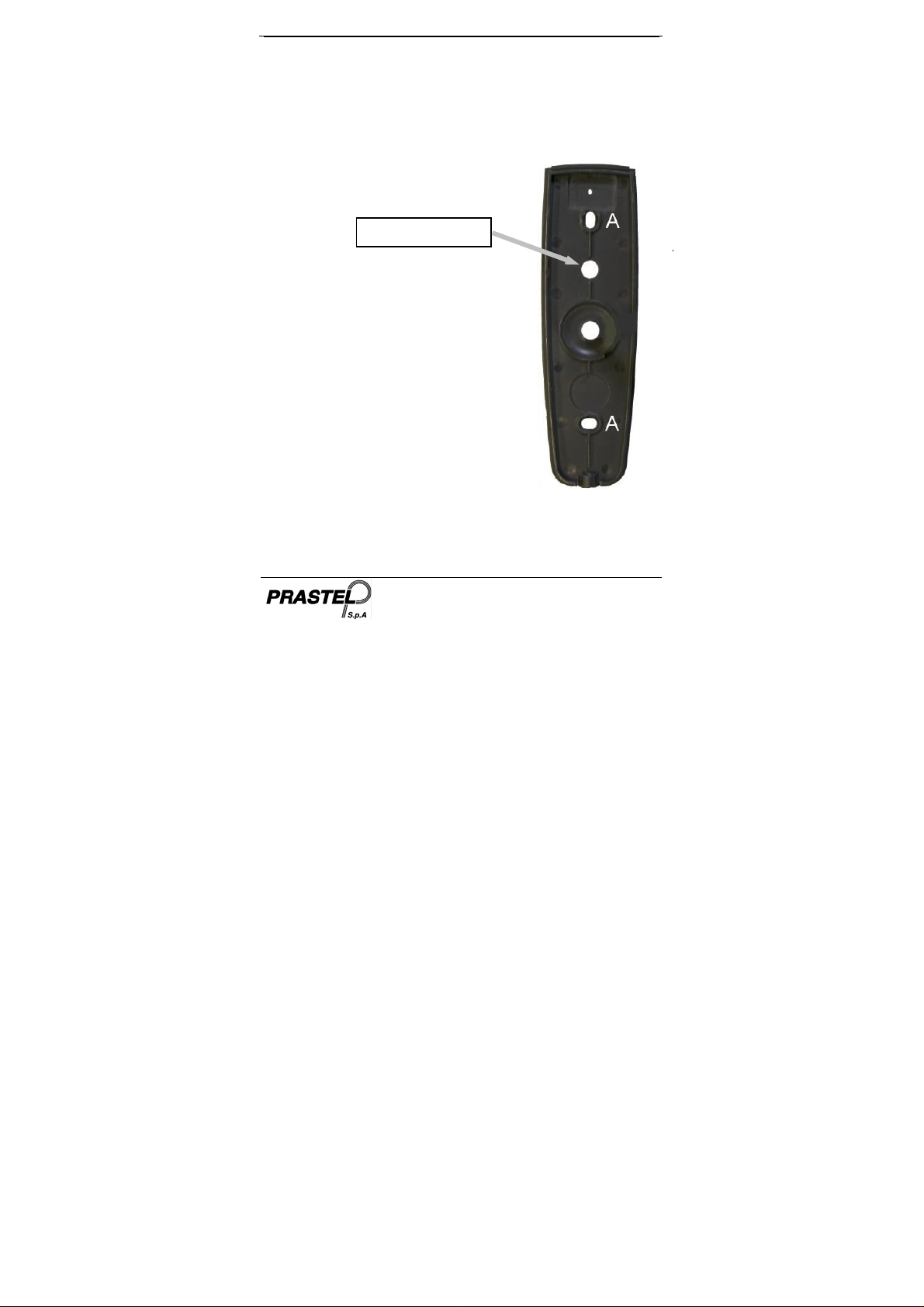
3. MOUNTING
Before starting, select the location to mount the EASYPL controller.
This location should be at shoulder height and on the same side as the
door handle.
points marked as A.
For fixing, drill two holes in correspondence of the two
1. Wire the controller according to the
wiring instructions on the following
page.
2. Screw the EASYPL back cover to its
mounting location.
3. Return the front cover of the EASYPL to
the mounted back plate.
4. Secure the front cover by using the
supplied screw.
3.1 Wiring the EASYPL
The controller is supplied with a 1 m pigtail,
having a 10 conductor cable. To wire the
EASYPL, perform the following steps.
1. Prepare the controller cable to the required length.
2. Splice the controller pigtail wires to the corresponding devices
and cover each connection. Refer to the wire color guide
CAUTION! DO NOT DRILL
This is the Tamper Lens
2
EASYPL
provided below and to the wiring diagrams provided on the
following pages.
ENGLISH
ISEASYPL_04_08.doc
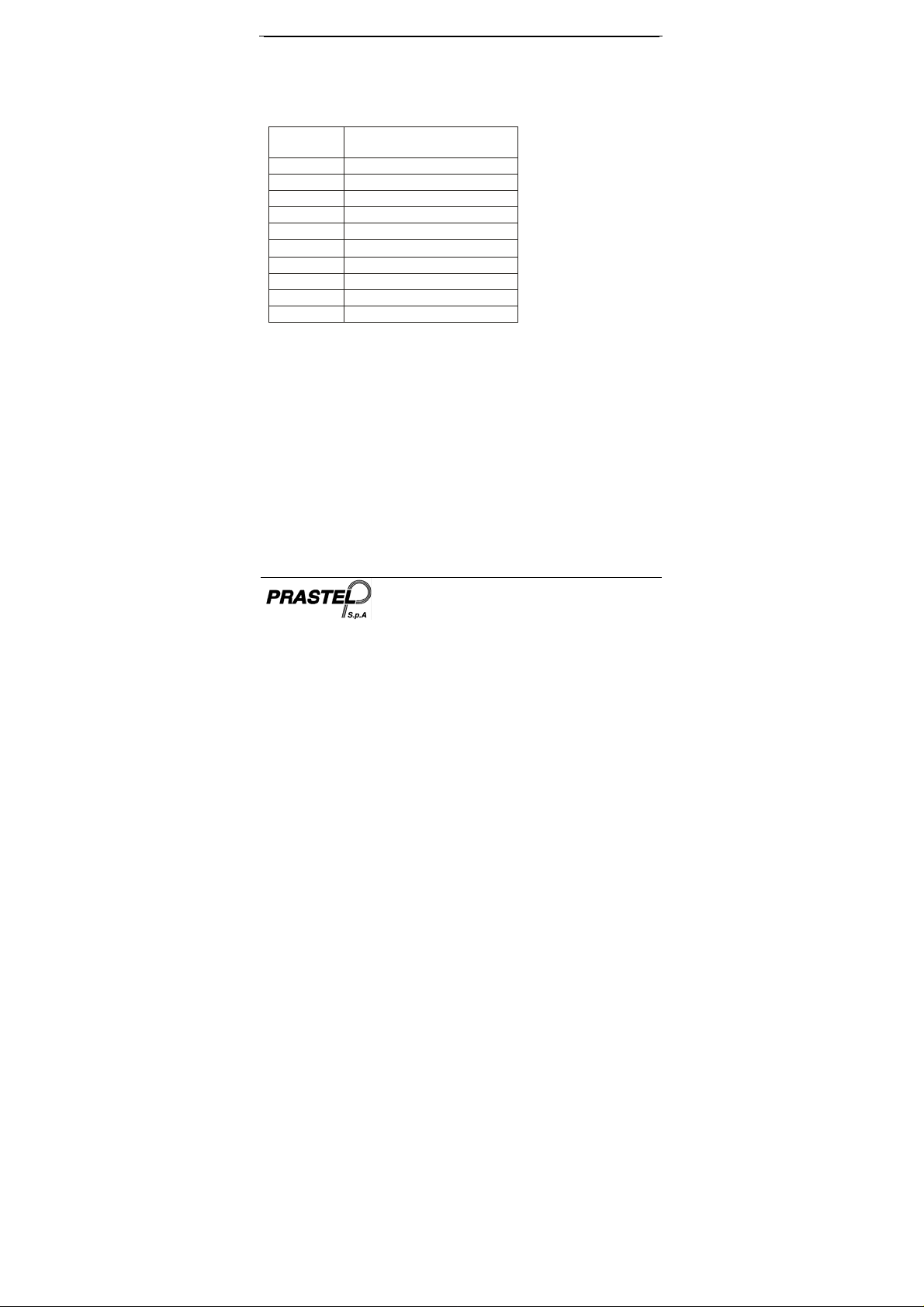
COLOR DESCRIPTION
RED
BLACK
GRE EN
WHITE
PURPLE
GRA Y
BROWN
BLUE
YE LLOW
ORA NG E
3) Trim and cover all conductors that are not used.
Two typical wiring diagrams are shown on the next pages.
V INPUT
GRO UND
REX / BL
IN / MONITOR
L OC K: C O M
N.O .
N.C.
AUX: COM
N.O.
N.C.
3
EASYPL
(+)
ENGLISH
ISEASYPL_04_08.doc
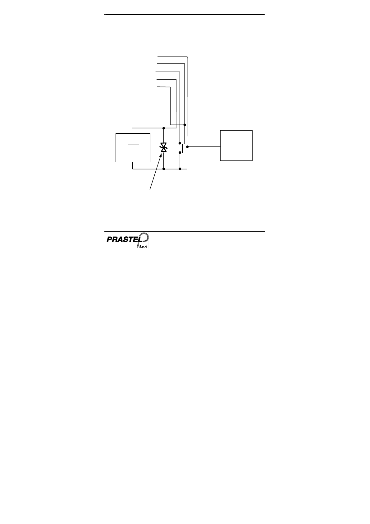
3.2 Wiring the Lock Strike Relay and REX
BLACK
RED
GREEN
GRAY
VIOLET
ELECRTIC LOCK
STRIKE
FAIL SAFE
or
FAIL SECURE
(-)
Varistor (optional)
(-)
(+)
POWER SUPPLY
12V – 24V AC/DC
(-)
COMMON
4
EASYPL
A
ENGLISH
ISEASYPL_04_08.doc
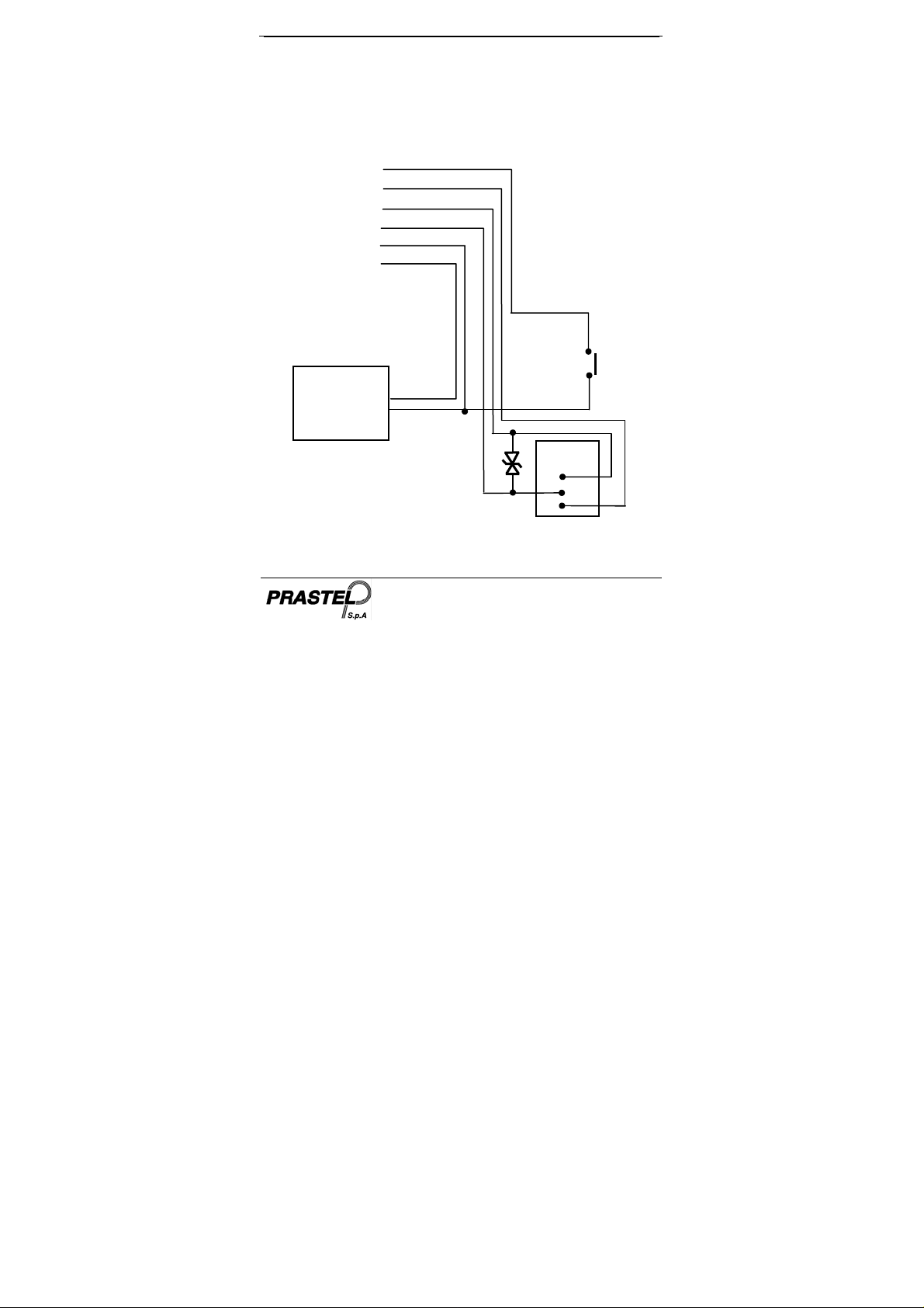
3.3 Wiring the Auxiliary Input and Output
WHITE
YELLOW
ORANGE
BLUE
BLACK
RED
COMMON
POWER SUPPLY
12V – 24V AC/DC
(+)
(-)
5
IN / MONITOR
(-)
uxiliary Relay
N.C.
COM
N.O.
EASYPL
ENGLISH
ISEASYPL_04_08.doc
4. NORMAL, SECURE & MASTER USERS
The EASYPL accepts up to 500 users and provides entry via the use of
PIN codes. Each user is provided with two code memory slots, Memory
Slot 1 (Primary Code) and Memory Slot 2 (Secondary Code).
The way in which the two memory slots are programmed determines a
users access level and also determines the way in which the EASYPL
grants access in its three Modes of Operation.
There are three user levels
Normal User
A Normal User only has a Primary Code and is only granted access
when the EASYPL is in Normal or Bypass Mode.
Secure User
A Secure User must have a Primary and Secondary Code
programmed, the two codes must not be the same. The Secure User
can gain access when the EASYPL is in any of its three Modes of
Operation. In Normal Mode the Secure User must use their Primary
Code to gain entry. In Secure Mode the Secure User must present
both their Primary and Secondary Codes in order to gain entry.
Master User
A Master User must have both Primary and Secondary Codes
programmed with the same PIN code. The Master User can gain
access during any Mode of Operation by presenting their PIN code to
the controller. (The Master User is convenient but is less secure than a
Secure User).
:
6
EASYPL
ENGLISH
ISEASYPL_04_08.doc
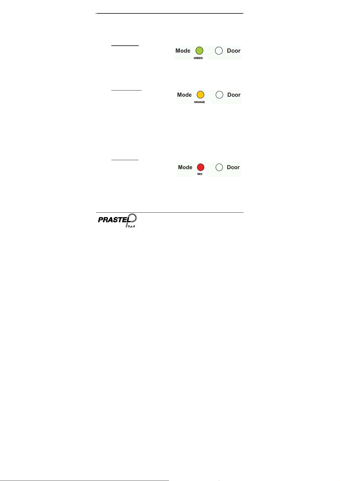
5. Modes of Operation
The EASYPL has 3 Modes of Operation:
1. Normal Mode
Normal Mode is the default mode
and the Mode LED is green. In
Normal Mode the door is locked
until a Primary Code is presented to the controller. Special codes such
as "Open Code" and "Auxiliary Code" are active in Normal mode. (see
par. 9 e 10).
2. Bypass Mode.
In Bypass mode the Mode LED is
orange. In Bypass Mode, access to
the premises is dependent on
whether the controller's Lock Strike Relay is programmed for Fail Safe
Operation or Fail Secure Operation.
When the Lock Strike Relay is programmed for Fail
Secure Operation, the door is locked until the Door Bell
Button is pressed.
When the Lock Strike Relay is programmed for Fail Safe
Operation, the door is constantly unlocked.
3. Secure Mode
In secure mode the LED is red. Only
Secure and Master Users can
access the premises during the
Secured Mode.
A Secure User must enter their Primary and Secondary Codes to gain
entry. After entering their Primary Code the Door LED will flash green
for 10 seconds, during which the Secondary Code must be entered.
A Master User only needs to present their PIN code once to gain entry.
7
EASYPL
ENGLISH
ISEASYPL_04_08.doc
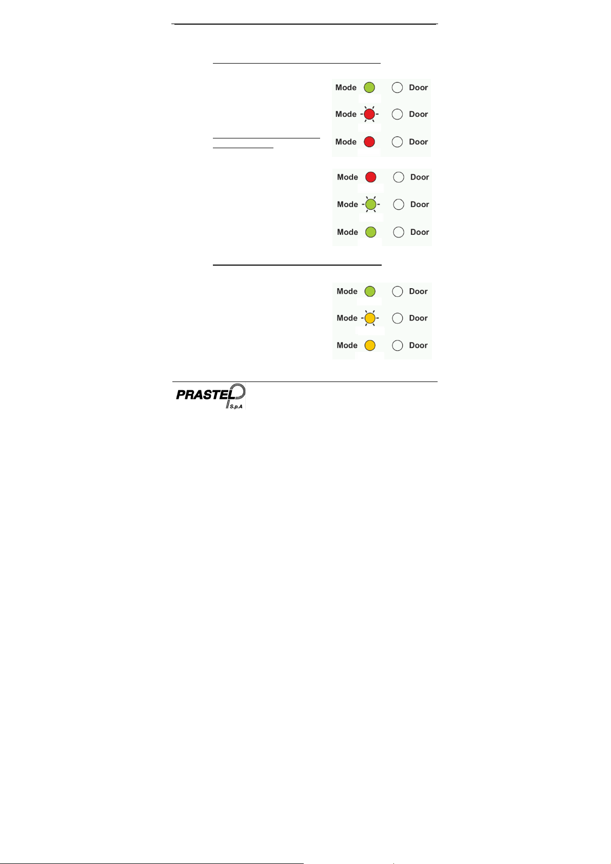
5.1 Changing the Modes of Operation
5.1.1 Changing from Normal Mode to Secure Mode:
The default factory setting for the Normal / Secure Code is 3838.
1. Enter the 4-digit Normal / Secure
Code. Mode LED will flash red
2. Press the "#" key to confirm the
Mode change. Mode LED is red.
5.1.2 Changing from Secure Mode
to Normal Mode:
The default factory setting for the
Normal / Secure Code 3838.
1. Enter the 4-digit Normal / Secure
Code. Mode LED will flash green.
2. Press the "#" key to confirm the
Mode change: the LED will turn
green. The EASYPL Auxiliary
Input can also be used to switch
the Mode of Operation from
Normal to Secure and vice versa.
(see par.12).
5.1.3 Changing from Normal Mode to Bypass Mode:
To set the Normal/Bypass code refer to par. 13).
1. Enter the 4 digit Normal / Bypass
Code. Mode LED will flash
orange.
2. Press the "#" key to confirm the
Mode change. Mode LED will turn
orange.
8
GREEN
RED
RED
RED
GREEN
GREEN
GREEN
ORANGE
ORANGE
 Loading...