

Page 1
6 3 3 5
DK
UK
FR
DE
ES
RU
2 - W i r e H A R T
T r a n s m i t t e r
N o . 6 3 3 5 V 1 0 9 - I N
F r o m s e r . n o . 1 0 0 9 2 4 0 0 0
S I G N A L S T H E B E S T
®
Page 2

DK
PR electronics A/S tilbyder et bredt program af analoge og digitale
signalbehandlingsmoduler til industriel automation. Programmet
består af Isolatorer, Displays, Ex-barrierer, Temperaturtransmittere,
Universaltransmittere mfl. Vi har modulerne, du kan stole på i selv
barske miljøer med elektrisk støj, vibrationer og temperaturudsving, og alle produkter opfylder de strengeste internationale standarder. Vores motto »Signals the Best« er indbegrebet af denne
filosofi – og din garanti for kvalitet.
UK
PR electronics A/S offers a wide range of analogue and digital
signal conditioning modules for industrial automation. The product
range includes Isolators, Displays, Ex Interfaces, Temperature
Transmitters, and Universal Modules. You can trust our products
in the most extreme environments with electrical noise, vibrations
and temperature fluctuations, and all products comply with the
most exacting international standards. »Signals the Best« is the
epitome of our philosophy – and your guarantee for quality.
FR
PR electronics A/S offre une large gamme de produits pour le
traite ment des signaux analogiques et numériques dans tous
les domaines industriels. La gamme de produits s’étend des
transmetteurs de température aux afficheurs, des isolateurs aux
interfaces SI, jusqu’aux modules universels. Vous pouvez compter
sur nos produits même dans les conditions d’utilisation sévères,
p.ex. bruit électrique, vibrations et fluctuations de température.
Tous nos produits sont conformes aux normes internationales les
plus strictes. Notre devise »SIGNALS the BEST« c’est notre ligne
de conduite - et pour vous l’assurance de la meilleure qualité.
DE
PR electronics A/S verfügt über ein breites Produktprogramm
an analogen und digitalen Signalverarbeitungsmodule für die industrielle Automatisierung. Dieses Programm umfasst Displays,
Temperaturtransmitter, Ex- und galvanische Signaltrenner, und
Universalgeräte. Sie können unsere Geräte auch unter extremen
Einsatzbedingungen wie elektrisches Rauschen, Erschütterungen
und Temperaturschwingungen vertrauen, und alle Produkte von
PR electronics werden in Überein stimmung mit den strengsten
internationalen Normen produziert. »Signals the Best« ist Ihre
Garantie für Qualität!
11 01
Page 3

2-WIRE HART® TRANSMITTER
PRETRANS 6335
CONTENTS
EC declaration of conformity ............................................. 2
Application ......................................................................... 3
Technical characteristics .................................................... 3
Mounting / installation ........................................................ 3
Applications ........................................................................ 4
Order: 6335 ........................................................................ 5
Electrical specifications ...................................................... 5
Connections ....................................................................... 9
Block diagram .................................................................... 11
Programming ...................................................................... 12
Connection of transmitters in multidrop mode .................. 14
Appendix ............................................................................ 15
ATEX Installation Drawing - 6335A .................................. 15
ATEX Installation Drawing - 6335D ................................. 15
IECEx installation drawing - 6335D ................................. 15
FM Installation Drawing No. 6335QF01 .......................... 15
CSA Installation Drawing No. 6335QC02 ....................... 15
633 5 V 109- I N 1
Page 4

EC DECLARATION OF CONFORMITY
CONTENTS
As manufacturer
PR electronics A/S
Lerbakken 10
DK-8410 Rønde
hereby declares that the following product:
Type: 6335
Name: 2-wire HART
is in conformity with the following directives and standards:
The EMC Directive 2004/108/EC and later amendments
EN 61326-1 : 2006
For specification of the acceptable EMC performance level, refer to the
electrical specifications for the module.
The ATEX Directive 94/9/EC and later amendments
EN 60079-0 : 2006, EN 60079-11 : 2007,
EN 60079-15 : 2005 and EN 60079-26 : 2007
ATEX certificate: KEMA 10ATEX0006 X (6335A)
ATEX certificate: KEMA 09ATEX0148 (6335D)
Notified body
KEMA Quality B.V. (0344)
Utrechtseweg 310, 6812 AR Arnhem
P.O. Box 5185, 6802 ED Arnhem
The Netherlands
®
transmitter
Rønde, 22 March 2010 Kim Rasmussen
Manufacturer’s signature
2 6335V10 9 - IN
Page 5

2-WIRE HART® TRANSMITTER
CONTENTS
PRETRANS 6335
• RTD, TC, Ohm, or mV input
• Extremely high measurement accuracy
• HART
®
communication
• Galvanic isolation
• 1- or 2-channel version
Application
• Linearised temperature measurement with Pt100...Pt1000, Ni100...Ni1000,
TC or sensor.
• Difference or average temperature measurement of 2 resistance or TC sensors.
• Conversion of linear resistance variation to a standard analogue current
signal, for instance from valves or Ohmic level sensors.
• Amplification of a bipolar mV signal to a standard 4...20 mA current signal.
• Connection of up to 15 channels to a digital 2-wire signal with
®
communication.
HART
Technical characteristics
• Within a few seconds the user can program PR6335 to measure temperatures
within all ranges defined by the norms.
• The RTD and resistance inputs have cable compensation for 2-, 3- and 4-wire
connection.
• The 6335 has been designed according to strict safety requirements and is
thus suitable for application in SIL 2 installations.
• A limit can be programmed on the output signal.
• Continuous check of vital stored data for safety reasons.
• Sensor error detection according to the guidelines in NAMUR NE 89.
Mounting / installation
• Mounted vertically or horizontally on a DIN rail. As the modules can be
mounted without any distance between neighbouring units, up to 84 channels
can be mounted per metre.
• NB: As Ex barrier for 6335D we recommend 5106B.
633 5 V 109- I N 3
Page 6
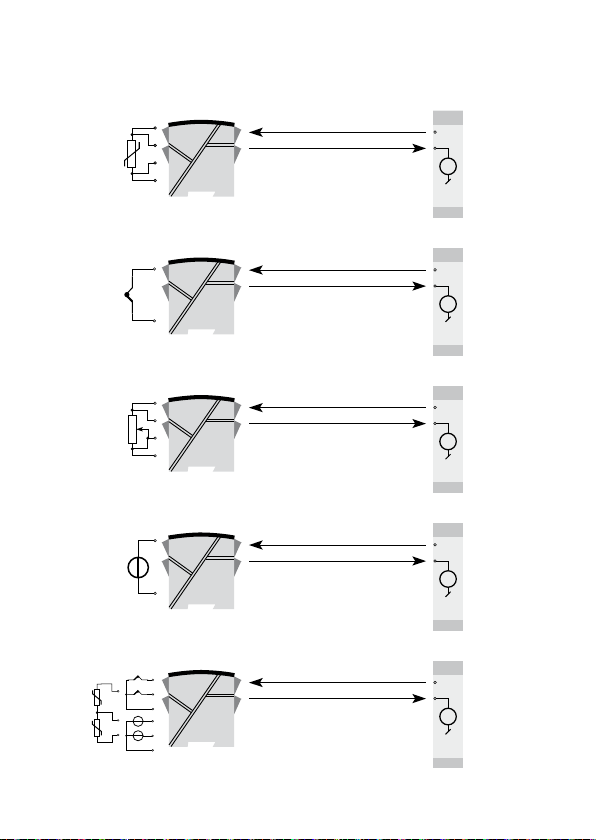
RTD to 4...20 mA
CONTENTS
APPLICATIONS
2-wire installation
in control room
V +
m A
TC to 4...20 mA
Resistance
to 4...20 mA
mV to 4...20 mA
Difference or average
RTD, TC or mV
1 2
2
1 2
1
2-wire installation
in control room
V +
m A
2-wire installation
in control room
V +
m A
2-wire installation
in control room
V +
m A
2-wire installation
in control room
V +
m A
4 6335V10 9 - IN
Page 7
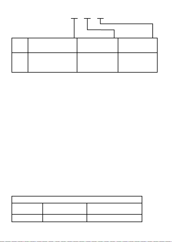
Order: 6335
CONTENTS
Type Version
6335
Standard : A
CSA, FM, : D
Galvanic
isolation
Channels
1500 VAC : 2 Single : A
Double : B
ATEX & IECEx
*NB! Please remember to order CJC connectors type 5910/5910Ex (channel 1)
and 5913/5913Ex (channel 2) for TC inputs with an internal CJC.
Electrical specifications
Specifications range:
-40°C to +60°C
Common specifications:
Supply voltage, DC
Standard............................................... 8.0...35 VDC
CSA, FM, ATEX & IECEx ...................... 8.0...30 VDC
Isolation voltage, test / operation ............... 1.5 kVAC / 50 VAC
Isolation voltage, channel 1 / channel 2:
Standard............................................... 3.75 kVAC
CSA, FM, ATEX & IECEx ...................... 1500 VAC
Warm-up time .............................................. 30 s
Communications interface .......................... Loop Link and HART
Signal / noise ratio ...................................... Min. 60 dB
Response time (programmable) .................. 1...60 s
EEprom error check .................................... < 10 s
Signal dynamics, input ................................ 22 bit
Signal dynamics, output.............................. 16 bit
Calibration temperature............................... 20...28°C
Accuracy, the greater of general and basic values:
®
General values
Input type
Absolute
accuracy
Temperature
coefficient
All ≤ ±0.05% of span ≤ ±0.005% of span / °C
633 5 V 109- I N 5
Page 8
CONTENTS
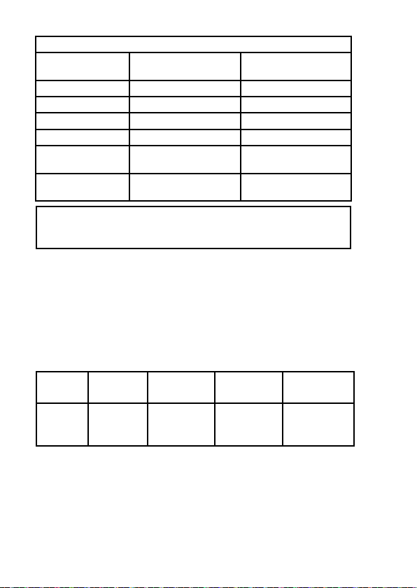
Pt100 and Pt1000 ≤ ±0.1°C ≤ ±0.005°C/°C
Ni100 ≤ ±0.2°C ≤ ±0.005°C/°C
Lin. R ≤ ±0.1 Ω ≤ ±5 mΩ / °C
Volt ≤ ±10 µV ≤ ±0.5 µV / °C
TC type:
E, J, K, L, N, T, U
TC type:
B, R, S, W3, W5
Effect of supply voltage variation ................ < 0.005% of span / VDC
Max. wire size .............................................. 1 x 1.5 mm
Humidity ...................................................... < 95% RH (non-cond.)
Dimensions .................................................. 109 x 23.5 x 104 mm
Protection degree ........................................ IP20
Weigh (1 / 2 channels) ................................. 145 / 185 g
Electrical specifications, inputs:
Max. offset................................................... 50% of selected numerical
max. value
RTD and linear resistance input:
Cable resistance per wire (max.) ................. 5 Ω
Sensor current ............................................. Nom. 0.2 mA
Effect of sensor cable resistance
(3- / 4-wire) .................................................. < 0.002 Ω / Ω
Sensor error detection ................................ Yes
Short circuit detection ................................. If 0% > 30 Ω
Input type
EMC immunity influence ..................................... < ±0.1% of span
Extended EMC immunity:
NAMUR NE 21, A criterion, burst ....................... < ±1% of span
RTD
type
Pt100
Ni100
Lin. R
Min.
value
-200°C
-60°C
0 Ω
Basic values
Basic
accuracy
≤ ±0.5°C
≤ ±1°C
Max.
value
+850°C
+250°C
7000 Ω
Temperature
coefficient
≤ ±0.025°C / °C
≤ ±0.1°C / °C
2
stranded wire
Min.
span Standard
10°C
10°C
10 Ω
IEC 60751
DIN 43760
-----
6 6335V10 9 - IN
Page 9
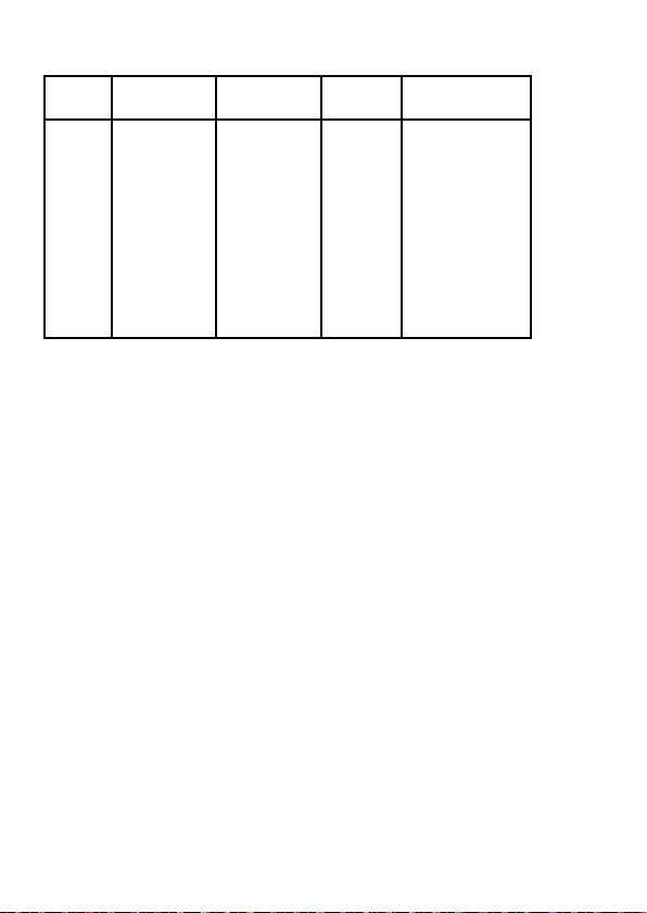
TC inputs:
CONTENTS
Type
B
E
J
K
L
N
R
S
T
U
W3
W5
Cold junction compensation ....................... < ±1.0°C
External CJC with Ni100 or Pt100 .............. -40 ≤ T
Sensor error detection ................................ Yes
Sensor error current:
When detecting .................................... Nom. 33 mA
Else....................................................... 0 mA
Short circuit detection ................................. If 0% > 5 mV
Voltage inputs:
Measurement range ................................... -800...+800 mV
Min. span ..................................................... 2.5 mV
Input resistance ........................................... 10 MΩ
Current output:
Signal range ................................................ 4...20 mA
Min. signal range ......................................... 16 mA
Updating time .............................................. 440 ms
(660 ms for diff.)
Fixed output signal ...................................... Between 4 and 20 mA
Output signal at EEprom error .................... ≤ 3.5 mA
Load resistance ........................................... ≤ (V
Load stability ............................................... < ±0.01% of span / 100 Ω
Sensor error detection:
Programmable ............................................. 3.5...23 mA
NAMUR NE43 Upscale ............................... 23 mA
NAMUR NE43 Downscale ........................... 3.5 mA
Of span = Of the presently selected range
Min.
temperature
+400°C
-100°C
-100°C
-180°C
-100°C
-180°C
-50°C
-50°C
-200°C
-200°C
0°C
0°C
Max.
temperature
+1820°C
+1000°C
+1200°C
+1372°C
+900°C
+1300°C
+1760°C
+1760°C
+400°C
+600°C
+2300°C
+2300°C
Min.
span
100°C
50°C
50°C
50°C
50°C
50°C
100°C
100°C
50°C
50°C
100°C
100°C
supply
Standard
IEC584
IEC584
IEC584
IEC584
DIN 43710
IEC584
IEC584
IEC584
IEC584
DIN 43710
ASTM E988-90
ASTM E988-90
≤ 135°C
amb.
- 8) / 0.023 [Ω ]
633 5 V 109- I N 7
Page 10

Ex approval - 6335A:
CONTENTS
KEMA 10ATEX0006 X .................................. II 3 G Ex nA [nL] IIC T4...T6 or
II 3 G Ex nL IIC T4...T6 or
II 3 G Ex nA [ic] IIC T4...T6 or
II 3 G Ex ic IIC T4...T6
ATEX Installation Drawing No. ............. 6335QA02
Ex / I.S. approvals - 6335D:
ATEX KEMA 09ATEX0148 ........................... II 1 G Ex ia IIC T6...T5
Max. ambient temperature for T6 ............... 40°C
Max. ambient temperature for T5 ............... 60°C
ATEX, applicable in zone ............................. 0, 1 or 2
ATEX Installation Drawing No. ............. 6335QA01
IECEx KEM 10.0084 .................................... Ex ia IIC T5 Ga
IECEx Installation Drawing No. ............ 6335QI01
FM, applicable in ......................................... IS, Class I, Div. 1, Group A, B, C, D
IS, Class I, Zone 0, AEx ia IIC
FM Installation Drawing No.................. 6335QF01
CSA, applicable in ....................................... IS, Class I, Div. 1, Group A, B, C, D,
Ex ia IIC
IS, Class I, Zone 0, AEx ia IIC
CSA Installation Drawing No. .............. 6335QC02
GOST R approval:
VNIIM & VNIIFTRI, Cert. no. ........................ See www.prelectronics.com
Observed authority requirements: Standard:
EMC 2004/108/EC ...................................... EN 61326-1
ATEX 94/9/EC .............................................. EN 60079-0, EN 60079-11,
EN 60079-15, EN 60079-26
IECEx ........................................................... IEC 60079-0, -11, 26
FM ............................................................... 3600, 3611, 3610
CSA, CAN / CSA ......................................... C22.2 No. 157, E60079-11, UL 913
8 6335V10 9 - IN
Page 11
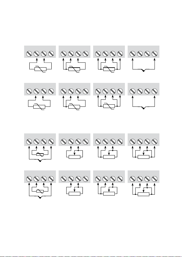
CONNECTIONS
CONTENTS
Inputs:
RTD, 2-wire RTD, 3-wire RTD, 4-wire
43
42 44
41 41 42 44
43
41 42 44
Channel 1
RTD, 2-wire RTD, 3-wire RTD, 4-wire
53
51 52 54
53
51 52 54
51 52 54
Channel 2
TC, external CJC
41 42 44
-
Channel 1 Channel 2
TC, external CJC
51 52 54
-
Resistance, 2-wire Resistance, 3-wire Resistance, 4-wire
43
+
53
+
43
41 42 44
Resistance, 2-wire Resistance, 3-wire Resistance, 4-wire
53
51 52 54
41 42 44
51 52 54
43
53
43
53
TC, internal CJC
CJC
41 42 44
+
-
TC, internal CJC
CJC
51 54
52
+
-
43
41 42 44
53
51 52 54
633 5 V 109- I N 9
Page 12
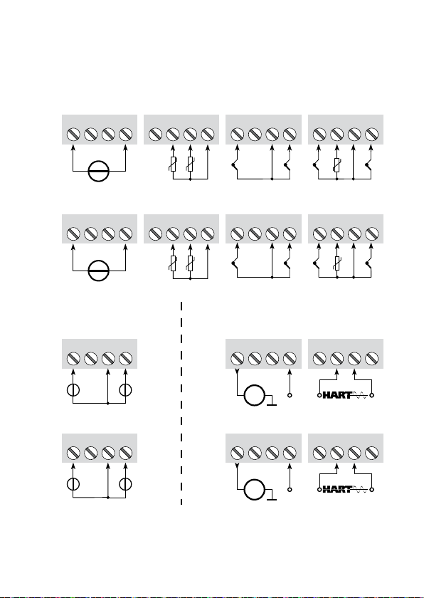
mV
CONTENTS
43
41 42 44
CONNECTIONS
Inputs:
RTD, difference
or average
43
41 42 44
with internal CJC
41 42 44
TC, difference
or average,
43
TC, difference
or average,
with external CJC
43
41 42 44
-
Channel 1
mV
51 52 54
-
Channel 2
mV, difference
or average
41 42 44
+
Channel 1 Channel 2
2
-
mV, difference
or average
51 52 54
+
2
-
53
43
53
+
+
+
1
-
+
1
-
2
1
RTD, difference
or average
53
51 52 54
2
1
+
2
-
TC, difference
or average,
with internal CJC
53
51 52 54
+
2
-
Outputs:
2-wire installation
13
11 12 14
m A
2-wire installation
23
21 22 24
m A
+
+
1
2
-
-
TC, difference
or average,
with external CJC
51 52 54
+
+
1
2
-
-
HART
11 12 14
+
HART
21 22 24
+
53
®
comm.
13
®
comm.
23
+
1
-
+
1
-
10 6335V10 9 - IN
Page 13

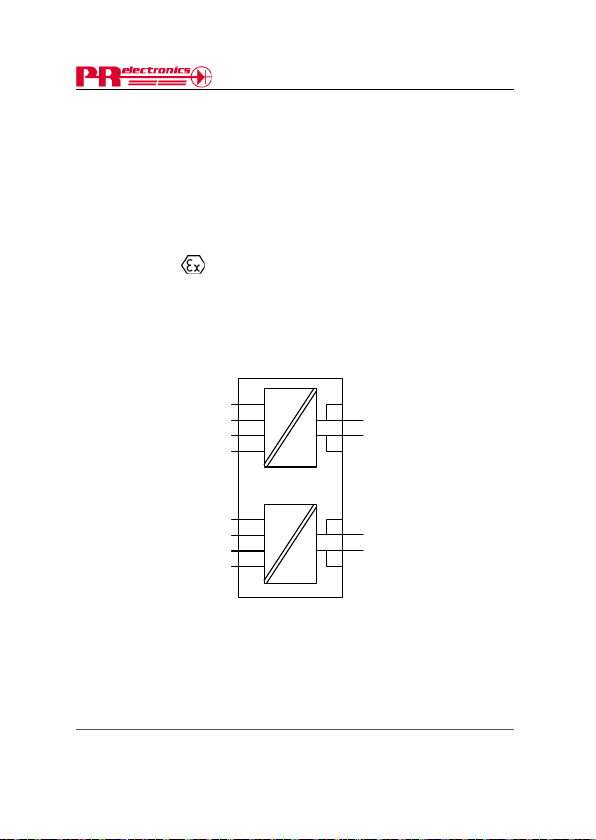
BLOCK DIAGRAM
0 . . . 1 6
m A
4 3 2
*
44
14
13
11
12
43
42
41
53
54
51
52
23
24
22
21
+
-
m V
m A
M U X
4 m A
6 3 3 5
6 3 3 5
PGA
D / A
A / D
CH 1
CH 2
+
-
C P U
E E P R O M
Supply -
4...20 mA
TC
mV
RTD, lin. R
- wire
Ex circuit, only 6335D
*
Internal CJC connectors must be ordered separately.
Supply +
HART
®
comm.
HART
®
comm.
Comm.
CONTENTS
633 5 V 109- I N 11
Page 14
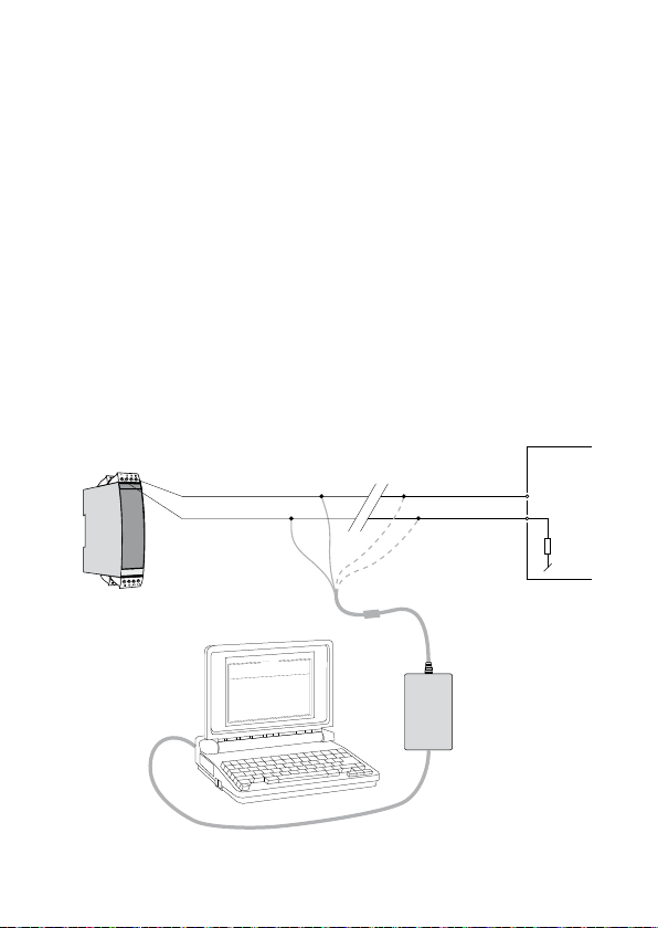
PROGRAMMING
CONTENTS
PRetrans 6335 can be configured in the following 3 ways:
1. With PR electronics A/S’ communications interface Loop Link and PReset PC
configuration software.
2. With a HART
3. With a HART
1: Loop Link
For programming please refer to the drawing below and the help functions in
PReset.
When communicating with non-installed modules, connectors 11, 12, 13, 14
(channel 1) and 21, 22, 23, 24 (channel 2) can be dismantled in the safe area
to connect the terminals of the communications interface to the pins.
Loop Link is not approved for communication with modules installed in
hazardous (Ex) area.
Order: Loop Link
P R e t r a n s 6 3 3 5
®
modem and PReset PC configuration software.
®
communicator with PR electronics A/S’ DDL driver.
1
1
1
2
1
3
1
4
1 2
5 1
14 (24)
11 (21)
4
4
3
4
2
4
4 1
Black
Disconn ect
Red
Connect or
0
0
:
0
3
:
8
0
n
o
t
i
p
O
e
ag
u
g
n
a
L
n
o
i
at
c
i
n
u
m
m
o
C
t
u
t
p
u
O
t
u
p
n
I
t
c
u
d
o
r
P
l
e
1
i
3
F
3
5
p
o
t
e
R
P
0
1
-
-
8
4
0
0
2
:
e
at
D
4
9
5
1
0
2
3
4
0
:
o
n
al
i
r
e
S
s
i
c
n
o
r
ct
l
e
e
R
P
:
o
n
ag
T
t
u
p
t
u
o
g
o
al
n
A
t
u
A
p
m
n
i
0
g
2
o
-
4
al
n
A
:
e
p
y
t
t
u
p
t
u
O
C
E
/
I
I
N
D
0
0
1
t
P
e
al
c
:
s
e
p
yp
U
t
t
u
:
p
r
n
o
I
r
r
e
r
o
s
n
e
S
C
0
0
.
0
5
-
0
0
.
0
:
e
g
an
r
t
u
p
n
I
e
r
i
w
-
3
:
n
i
o
ct
e
n
n
o
C
-
-
-
-
-
-
:
p
m
o
c
n
i
o
t
c
n
u
j
d
l
o
C
c
e
s
0
0
.
1
:
e
i
m
t
se
n
o
p
s
e
R
*
Yellow
Green
*
Loop
Link
5909 - USB
5905 - RS232
Receivi ng
equipme nt
+Vsuppl y
Input
12 6335V10 9 - IN
* Connected only for
on-line progra mming
Page 15
2: HART® modem
CONTENTS
For programming please refer to the drawing below and the help functions in
PReset.
1
1
1
2
1
3
1
4
1 2
5 1
4 4
3
4
2
4
4 1
P R e t r a n s 6 3 3 5
HART
®
communicator
®
modem 276D
1 3 ( 2 3 )
1 2 ( 2 2 )
t
a
c
i
n
u
m
m
o
C
t
u
p
t
u
O
t
u
p
n
I
t
c
u
d
o
r
P
e
l
i
3
3
F
5
p
o
t
e
R
P
0
-
1
8
-
4
9
9
1
:
e
t
a
D
4
9
5
1
0
2
3
4
9
:
o
n
l
i
a
r
e
S
s
c
i
n
o
r
t
c
e
l
e
R
P
:
o
n
g
a
T
t
u
p
i
n
g
l
o
a
n
A
O
C
I
E
/
N
I
D
0
0
1
t
P
:
e
p
y
t
t
u
p
n
I
S
C
0
.
0
0
5
-
0
.
0
0
:
e
g
n
a
r
t
u
p
n
®
modem
®
communicator 275D
I
e
i
r
-
w
3
:
n
i
o
t
c
e
n
n
o
C
-
-
-
-
-
:
p
m
o
c
n
o
i
t
c
n
j
u
l
d
o
C
c
e
s
0
.
0
1
:
e
m
i
t
e
s
n
o
p
s
e
R
Rload > 250 Ω , < 1100 Ω
0
0
:
0
3
:
8
0
n
o
i
t
p
O
e
g
a
u
g
n
a
L
n
o
i
1
t
u
p
t
u
o
g
l
o
a
n
A
A
m
0
2
-
4
:
e
p
y
t
t
u
p
t
u
e
l
a
c
s
p
U
:
r
o
r
r
e
r
o
s
n
e
®
communicator must be loaded with the
Receivin g
equipmen t
+Vsupply
Input
®
Order: HART
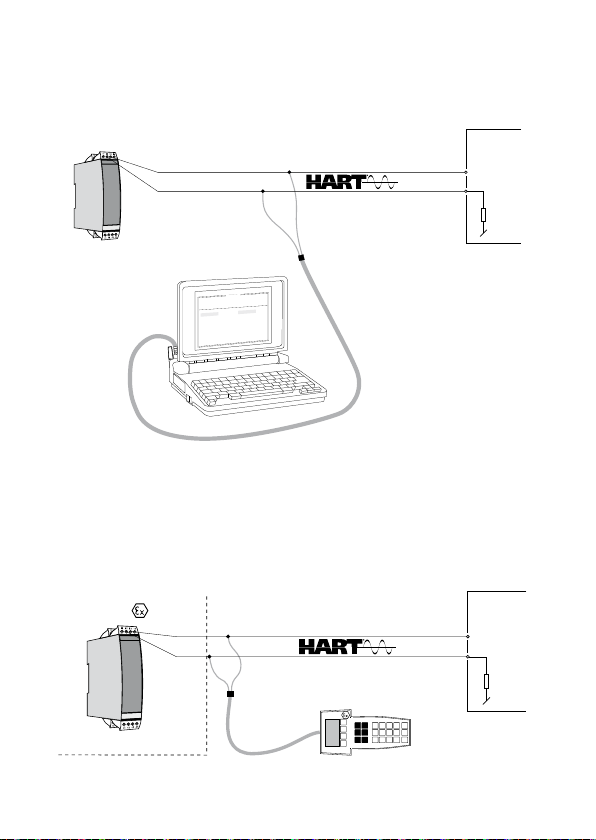
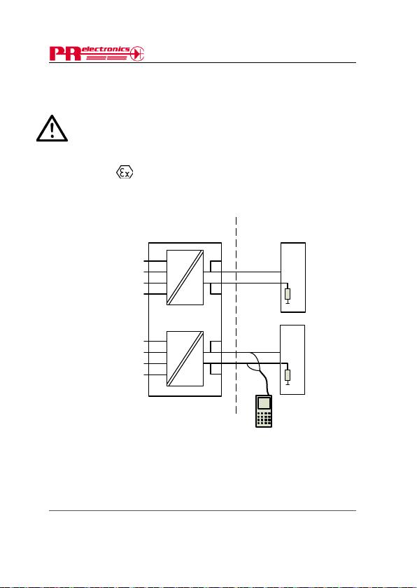
3: HART
For programming please refer to the drawing below. To get access to product-
specific commands, the HART
PR electronics A/S DDL driver. This can be ordered either at the HART
Communica tion Foundation or PR electronics A/S.
Order: HART
1
1
1
2
1
3
1
4
1 2
5 1
4
4
3
4
2
4
4 1
P R e t r a n s 6 3 3 5
area
1 3 ( 2 3 )
12 (22)
1 2 ( 2 2 )
Safe area
Rload
> 250 Ω, < 1 100 Ω
633 5 V 109- I N 13
Receivi ng
equipme nt
+Vsuppl y
Input
Page 16
CONNECTION OF TRANSMITTERS
CONTENTS
IN MULTIDROP MODE
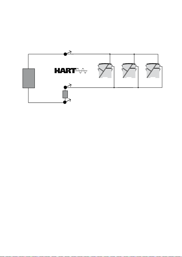
• The HART® communicator or a PC modem can be connected accross AB or
BC.
+
R
A
B
-
Rload
C
PRetrans
> 250 Ω, < 1100 Ω
6335
PRetrans
6335
Max. 15 channels
®
communicator or a
PRetrans
6335
+
Power
supply
-
• The outputs of max. 15 transmitters can be conected in parallel for a digital
®
communication on 2-wires.
HART
• Before it is connected, each transmitter must be configured with a unique
number from 1 to 15. If 2 transmitters are configured with the same number,
both will be excluded. The transmitters must be programmed for multidrop
mode (with a fixed output signal of 4 mA). Maximum current in the loop is
therefore 60 mA.
• The communication is either by means of a HART
®
modem.
HART
• The PReset PC configuration software can configure the individual transmitter
for multidrop mode and provide it with a unique polling address.
14 6335V10 9 - IN
Page 17

APPENDIX
CONTENTS
ATEX INSTALLATION DRAWING - 6335A
ATEX INSTALLATION DRAWING - 6335D
IECEX INSTALLATION DRAWING - 6335D
FM INSTALLATION DRAWING NO. 6335QF01
CSA INSTALLATION DRAWING NO. 6335QC02
633 5 V 109- I N 15
Page 18
CONTENTS
6335QA02
LERBAKKEN 10, 8410 RØNDE DENMARK. WWW.PRELECTRONICS.COM
For safe installation of 6335A the following must be observed. The module shall only be installed
by qualified personnel who are familiar with the national and international laws, directives and
standards that apply to this area.
Year of manufacture can be taken from the first two digits in the serial number.
ATEX Certificate KEMA 10ATEX 0006X
Marking
Standards EN 60079-0 : 2006, EN 60079-11 : 2007, EN 60079-15 : 2005
T5: -40ºC to 60 ºC
T6: -40ºC to 40 ºC
Terminal:
41,42,43,44 /
51,52,53,54
Ex nA [nL]
Uo: 9.6 VDC
Io: 28 mA
Po: 67 mW
Lo: 35 mH
Co: 3.5 μF
Special conditions for safe use:
For use in a potentially explosive atmosphere of flammable gasses, vapours or mists, the
transmitter shall be mounted in an enclosure providing a degree of protection of at least IP54 in
accordance to EN60529.
ATEX Installation drawing
II 3 G Ex nA [nL] IIC T6..T5
II 3 G Ex nL IIC T6..T5
II 3 G Ex nA [ic] IIC T6..T5
II 3 G Ex ic IIC T6..T5
Hazardous Area Zone 2
44
43
42
41
54
53
52
51
14
Terminal:
13
+
11-13 / 21-23
12
-
Ex nA
11
CH1
CH2
6335
U ≤ 35 VDC
I = 4 - 20 mA
Ex nL or Ex ic
24
23
+
Ui = 35 VDC
Li = 10 μH
22
-
Ci = 2.0 nF
21
Revision date:
2009-11-17
Version Revision
V1R0
16 6335V10 9 - IN
Page:
1/1
Page 19
CONTENTS
6335QA01
LERBAKKEN 10, 8410 RØNDE DENMARK. WWW.PRELECTRONICS.COM
6335
For safe installation of 6335D the following must be observed. The module shall only be installed by
qualified personnel who are familiar with the national and international laws, directives and
standards that apply to this area.
Year of manufacture can be taken from the first two digits in the serial number.
ATEX Certificate KEMA 09ATEX 0148
Marking
Standards EN 60079-0 : 2006, EN 60079-11 : 2007, EN 60079-26 : 2007
Hazardous area
Zone 0, 1, 2
T5: -40 ≤ Ta ≤ 60ºC
T6: -40 ≤ Ta ≤ 40ºC
Terminal:
41,42,43,44
Uo: 9.6 VDC
Io: 28 mA
Po: 67 mW
Lo: 35 mH
Co: 3.5 μF
Terminal:
51,52,53,54
Uo: 9.6 VDC
Io: 28 mA
Po: 67 mW
Lo: 35 mH
Co: 3.5 μF
Installation notes
The Instructions provided with the equipment shall be followed in detail to assure safe
operati on.
Revision date:
2009-09-29
ATEX Installation drawing
II 1 G Ex ia IIC T6...T5
44
43
42
41
CH1
54
53
52
51
CH2
Terminal:
11,12,13,14 and
21,22,23,24
Ui: 30 VDC
Ii: 120 mA
Pi: 0.84 W
Li: 10 μH
Ci: 2.0nF
Version Revision
6335
V1R0
Non Hazardous Area
14
13
+
12
-
11
24
+
23
22
-
21
R
Barrier
250 < R < 1100 ohm
R
Barrier
Ex HART
Communicator
0Page:
1/1
633 5 V 109- I N 17
Page 20
CONTENTS
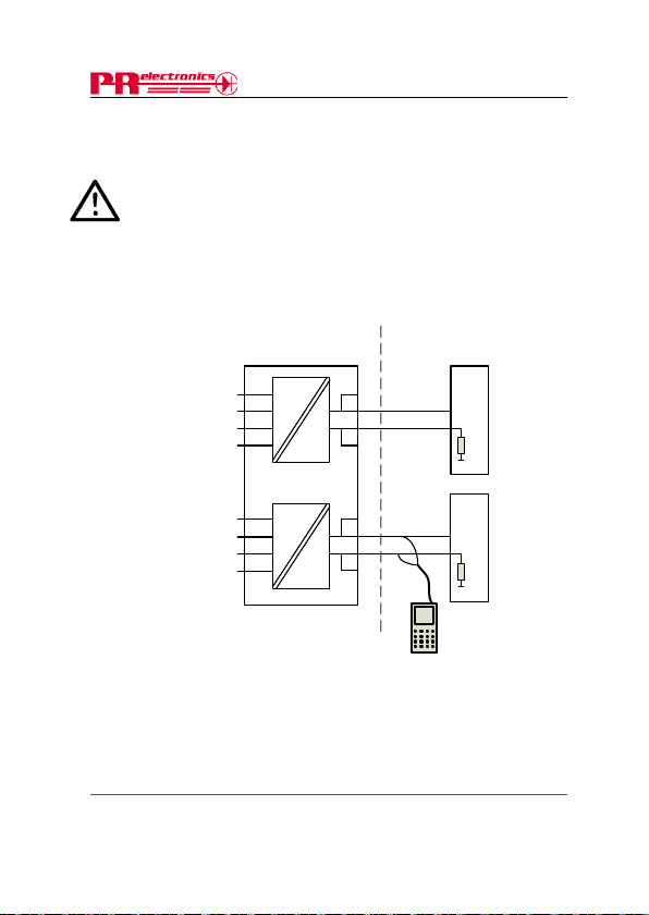
6335QI01
LERBAKKEN 10, 8410 RØNDE DENMARK. WWW.PRELECTRONICS.COM
For safe installation of 6335D or 6336D the following must be observed. The module shall only be
installed by qualified personnel who are familiar with the national and international laws, directives
and standards that apply to this area.
Year of manufacture can be taken from the first two digits in the serial number.
IECEx Certificate IECEx KEM.10.0084
Marking
Standards IEC60079-11:2006, IEC60079-0: 2007, IEC60079-26: 2006
Hazardous area
Zone 0, 1, 2
T5: -40 ≤ Ta ≤ 60ºC
Terminal:
41,42,43,44
Uo: 9.6 VDC
Io: 28 mA
Po: 67 mW
Lo: 35 mH
Co: 3.5 μF
Terminal:
51,52,53,54
Uo: 9.6 VDC
Io: 28 mA
Po: 67 mW
Lo: 35 mH
Co: 3.5 μF
Installation notes
The Instructions provided with the equipment shall be followed in detail to assure safe
operati on.
Revision date:
2010-05-28
IECEx Installation drawing
Ex ia IIC T5 Ga
44
43
42
41
CH1
54
53
52
51
CH2
Terminal:
11,12,13,14 and
21,22,23,24
Ui: 30 VDC
Ii: 120 mA
Pi: 0.84 W
Li: 10 μH
Ci: 2.0 nF
Version Revision
V2R0
6335D
6336D
Non Hazardous Area
14
13
+
12
-
11
24
23
+
22
-
21
R
Barrier
250 < R < 1100 ohm
R
Barrier
Ex HART
Communicator
Page:
1/1
18 6335V10 9 - IN
Page 21
CONTENTS
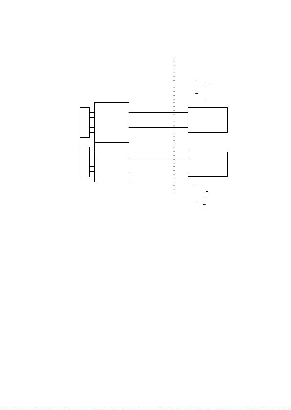
Installation Drawing 6335QF01
Model 6335C, 6335D
Class I,Division1, Groups, A,B,C,D
Class II Division 1 Groups E,F,G
Class I, Zone 0, IIC
Ambient temperature limits
T6: -40 to + 60 deg. Celcius
Terminal 41,42,43,44
Vt or Uo: 9,6 V
It or Io: 28 mA
Pt or Po: 67.2 mW
Ca or Co: 3.5 uF
La or Lo: 35 mH
Terminal 51,52,53,54
Vt or Uo: 9,6 V
It or Io: 28 mA
Pt or Po: 67.2 mW
Ca or Co: 3.5 uF
La or Lo: 35 mH
Installation notes.
The Transmitter must be installed in a suitable enclosure to meet installation codes
stipulated in The National Electrical Code (ANSI-NFPA 70).
When installed in Class II locations the Transmitter shall be installed in an enclosure
with a specified ingress protections of IP6X according to IEC60529 and Dust-tight
conduit seals must be used.
Equipment that is FM-approved for intrinsic safety may be connected to barriers
based on the ENTITY CONCEPT. This concept permits interconnection of approved
transmitters, meters and other devices in combinations which have not been
specifically examined by FM, provided that the agency's criteria are met. The
combination is then intrinsically safe, if the entity concept is acceptable to the
authority having jurisdiction over the installation.
The entity concept criteria are as follows:
The intrinsically safe devices, other than barriers, must not be a source of power.
The maximum voltage Ui(V
which the device can receive and remain intrinsically safe, must be equal to or
S
E
N
S
O
R
Ch 1
S
E
N
S
O
R
Ch 2
Terminal 11, 14
Vmax or Ui: 30 V
Imax or Ii: 120 mA
Pmax or Pi: 0.84 W
Ci: 1 nF
Li:10 uH
Terminal 21, 24
Vmax or Ui: 30 V
Imax or Ii: 120 mA
Pmax or Pi: 0.84 W
Ci: 1 nF
Li:10 uH
MAX
) and current Ii(I
Non Hazardous LocationHazardous (Classified) Location
Um < 250V
Voc or Uo < Vmax or Ui
Isc or Io < Imax or Ii
Po < Pi
Ca or Co > Ci + Ccable
La or Lo > Li + Lcable
+
Associated Apparatus
-
entity Parameters:
+
Associated Apparatus
-
entity Parameters:
Um < 250V
Voc or Uo < Vmax or Ui
Isc or Io < Imax or Ii
Po < Pi
Ca or Co > Ci + Ccable
La or Lo > Li + Lcable
MAX
), and maximum power Pi(Pmax),
or Barrier
with
or Barrier
with
6335QF01revAC.doc 2005-12-16 1/2
633 5 V 109- I N 19
Page 22

greater than the voltage (Uo or VOC or Vt) and current (Io or ISC or It) and the power Po
CONTENTS
which can be delivered by the barrier.
The sum of the maximum unprotected capacitance (C
and the interconnecting wiring must be less than the capacitance (C
safely connected to the barrier.
The sum of the maximum unprotected inductance (L
the interconnecting wiring must be less than the inductance (L
connected to the barrier.
The entity parameters Uo,V
provided by the barrier manufacturer.
OC
or Vt and Io,ISC or It, and Ca and La for barriers are
i
) for each intrinsically device
i
) for each intrinsically device and
a
) which can be
a
) which can be safely
6335QF01revAC.doc 2005-12-16 2/2
20 6335V10 9 - IN
Page 23
CONTENTS
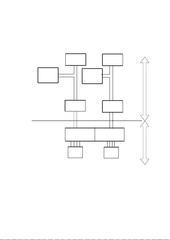
CSA Installation Drawing 6335QC02.
6335D transmitters are approved as intrinsically safe in Zone 0 Group IIC or
Class I,Division1,Group A,B,C,D when installed according to Installation Drawing.
1. Connections with separate power supply and receiver.
Output: Standard 4 - 20mA loop
Separate Power
Supply
Intrinsically safe
Barrier Parameters.
Uo(Voc) =< 30V
Io(Isc) =< 120mA
Po =< 0,84 W
Co(Ca)>Sum(Ci+Ccable)
Lo(La)>Sum(Li+Lcable)
-
+
Receiving
Instrument
- +
CSA approved
Barrier
+ -
Separate Power
Supply
Receiving
Instrument
-
+
CSA approved
Barrier
-+
+-
Non-hazardous
location
max 250V
Ambient temperature limits
T6:-40 to + 60 deg. Celcius
Terminal:11-14 and 21-24
Ui(Vmax) = 30V
Ii(Imax) = 120mA
Pi = 0.84W
Ci = 1 nF
Li = 10 uH
Terminal:41-44 and 51-54
Uo(Voc) = 9,6 V
Io(Isc) = 28 mA
Po = 67,2 mW
Co(Ca) = 3,5 uF
Lo(La) = 35 mH
Warning:
Substitution of components may impair intrinsic safety.
Channel 1 and Channel 2 are separate channels and therefore separate shielded
cables shall be used for each channel.
The 6335 must be installed in a suitable enclosure to meet installation codes
stipulated in the Canadian Electrical Code (CEC).
6335QC02.DOC 2006-01-04 Rev. AB 1/2
14 11 24 21
Channel 1 Channel 2
41
SENSOR 1
6335D
44
51 54
SENSOR 2
633 5 V 109- I N 21
Hazardous
Locations /
Sécurité
Intrinséque
Page 24
CONTENTS
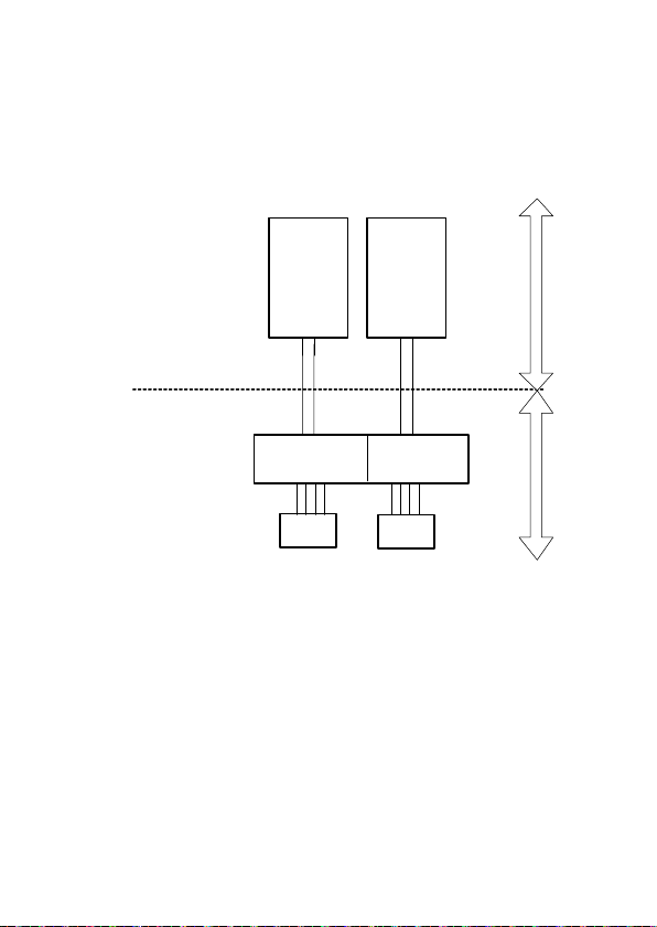
2. Connection with power
Output: Standard 4 - 20mA loop
supply and barrier built into receiver.
Intrinsically safe
Barrier Parameters.
Uo(Voc) =< 30V
Io(Isc) =< 120mA
Po =< 0,84 W
Co(Ca)>Sum(Ci+Ccable)
Lo(La)>Sum(Li+Lcable)
Ambient temperature limits
T6: -40 to + 60 deg. Celcius
Terminal:11-14 and 21-24
Ui(Vmax) = 30V
Ii(Imax) = 120mA
Pi = 0.84W
Ci = 1 nF
Li = 10 uH
Terminal:41-44 and 51-54
Uo(Voc) = 9,6 V
Io(Isc) = 28 mA
Po = 67,2 mW
Co(Ca) = 3,5 uF
Lo(La) = 35 mH
Warning:
Substitution of components may impair intrinsic safety.
Channel 1 and Channel 2 are separate channels and therefore separate shielded
cables shall be used for each channel.
The 6335 must be installed in a suitable enclosure to meet installation codes
stipulated in the Canadian Electrical Code (CEC).
6335QC02.DOC 2006-01-04 Rev. AB 2/2
Transmitter
Power Supply
built into
CSA approved
Receiving
Instrument
+ -
14 11 21
SENSOR 1
Transmitter
Power Supply
built into
CSA approved
Receiving
Instrument
+
6335D
24
Channel 2Channel 1
54 51
4144
SENSOR 2
Non-hazardous
location
max 250 V
-
Hazardous
Locations /
Sécurité
Intrinséque
22 6335V10 9 - IN
Page 25

Displays
Programmable displays with a wide
selection of inputs and outputs for display of temperature,
volume and weight, etc. Feature linearisation, scaling,
and difference measurement functions for programming
via PReset software.
Ex interfaces
signals as well as HART
Interfaces for analogue and digital
®
signals between sensors / I/P
converters / frequency signals and control systems in Ex
zone 0, 1 & 2 and for some modules in zone 20, 21 & 22.
Isolation
digital signals as well as HART
Galvanic isolators for analogue and
®
signals. A wide product
range with both loop-powered and universal isolators
featuring linearisation, inversion, and scaling of output
signals.
Temperature
A wide selection of transmitters for DIN
form B mounting and DIN rail modules with analogue
and digital bus communication ranging from applicationspecific to universal transmitters.
Universal
PC or front programmable modules with
universal options for input, output and supply. This range
offers a number of advanced features such as process
calibration, linearisation and auto-diagnosis.
Page 26
www.prelectronics.fr
[email protected]
www.prelectronics.de
[email protected]
www.prelectronics.es
[email protected]
www.prelectronics.it
[email protected]
www.prelectronics.se
[email protected]
www.prelectronics.co.uk
[email protected]
www.prelectronics.com
[email protected]
Head office
Denmark www.prelectronics.com
PR electronics A/S [email protected]
Lerbakken 10 tel. +45 86 37 26 77
DK-8410 Rønde fax +45 86 37 30 85
 Loading...