

Page 1
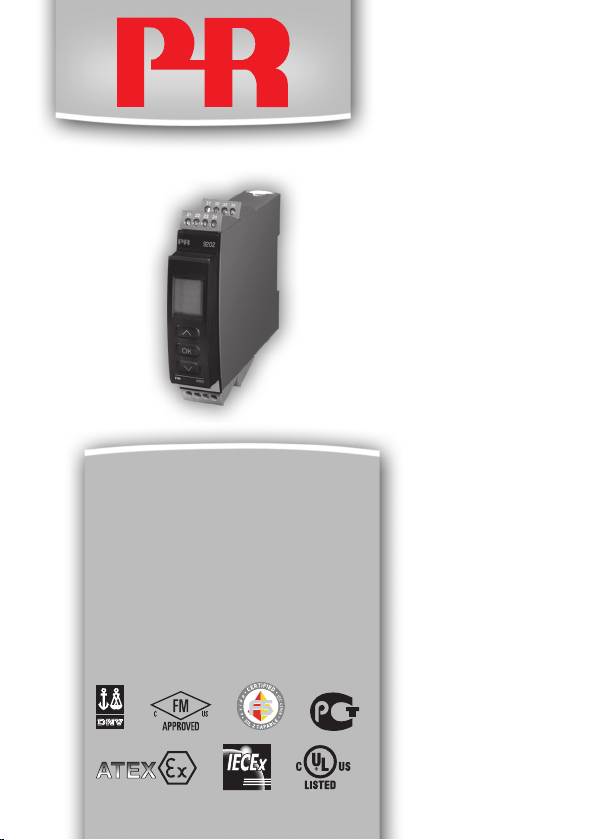
9202
Pulse isolator
Nr. 9202V103-DK
Produktversion: 9202-003
SIGNALS THE BEST
Page 2

PR electronics A/S tilbyder et bredt program af analoge og digitale
DK
signalbehandlingsmoduler til industriel automation. Programmet
består af Isolatorer, Displays, Ex-barrierer, Temperaturtransmittere,
Universaltransmittere m. Vi har modulerne, du kan stole på i selv
barske miljøer med elektrisk støj, vibrationer og temperaturudsving, og alle produkter opfylder de strengeste internationale standarder. Vores motto »Signals the Best« er indbegrebet af denne
loso – og din garanti for kvalitet.
PR electronics A/S offers a wide range of analogue and digital
UK
signal conditioning modules for industrial automation. The product
range includes Isolators, Displays, Ex Interfaces, Temperature
Transmitters, and Universal Modules. You can trust our products
in the most extreme environments with electrical noise, vibrations
and temperature uctuations, and all products comply with the
most exacting international standards. »Signals the Best« is the
epitome of our philosophy – and your guarantee for quality.
PR electronics A/S offre une large gamme de produits pour le
FR
traite ment des signaux analogiques et numériques dans tous
les domaines industriels. La gamme de produits s’étend des
transmetteurs de température aux afcheurs, des isolateurs aux
interfaces SI, jusqu’aux modules universels. Vous pouvez compter
sur nos produits même dans les conditions d’utilisation sévères,
p.ex. bruit électrique, vibrations et uctuations de température.
Tous nos produits sont conformes aux normes internationales les
plus strictes. Notre devise »SIGNALS the BEST« c’est notre ligne
de conduite - et pour vous l’assurance de la meilleure qualité.
PR electronics A/S verfügt über ein breites Produktprogramm
DE
an analogen und digitalen Signalverarbeitungsmodule für die industrielle Automatisierung. Dieses Programm umfasst Displays,
Temperaturtransmitter, Ex- und galvanische Signaltrenner, und
Universalgeräte. Sie können unsere Geräte auch unter extremen
Einsatzbedingungen wie elektrisches Rauschen, Erschütterungen
und Temperaturschwingungen vertrauen, und alle Produkte von
PR electronics werden in Überein stimmung mit den strengsten
internationalen Normen produziert. »Signals the Best« ist Ihre
Garantie für Qualität!
1226
Page 3

PULSE ISOLATOR
9202
INDHOLD
Advarsel .............................................................................. 2
Signaturforklaring ............................................................... 2
Sikkerhedsregler ................................................................. 2
Afmontering af system 9000 .............................................. 4
EF-Overensstemmelseserklæring ...................................... 5
Avancerede features........................................................... 6
Anvendelse ......................................................................... 6
Teknisk karakteristik ........................................................... 6
Applikationer ...................................................................... 7
PR 4501 Display- / programmeringsfront .......................... 8
Bestillingsskema 9202B ..................................................... 9
Elektriske specifikationer.................................................... 9
Konfigurering af kabelfejlscheck ........................................ 11
Funktionsbeskrivelse .......................................................... 12
Tilslutninger ........................................................................ 13
Blokdiagram ....................................................................... 14
Visning af signal- og kabelfejl uden displayfront ............... 15
Programmering / betjening af trykknapper ........................ 16
Rullende hjælpetekster i displaylinie 3 ............................... 18
Rutediagram ....................................................................... 19
Rutediagram, Avancerede indstillinger (ADV.SET) ............. 20
Appendix ............................................................................ 21
IECEx Installation Drawing .............................................. 22
ATEX Installationstegning ................................................ 24
FM Installation Drawing ................................................... 26
Safety Manual .................................................................. 28
9202 - Product Version 9202-003 1
Page 4
Følgende operationer bør kun udføres på modulet i spændings-
ADVARSEL
løs tilstand og under ESD-sikre forhold:
Installation, ledningsmontage og -demontage.
Fejlfinding på modulet.
Reparation af modulet og udskiftning af sikringer må kun
foretages af PR electronics A/S.
Modulets frontplade må ikke åbnes, da dette vil medføre skade
på stikforbindelsen til display- / programmeringsfronten PR
4501. Modulet indeholder ingen DIP-switche eller jumpere.
SIGNATURFORKLARING
ADVARSEL
Trekant med udråbstegn: Læs manualen før installation og idriftsættelse
af modulet for at undgå hændelser, der kan føre til skade på personer
eller materiel.
CE-mærket er det synlige tegn på modulets overensstemmelse med EU
-direktivernes krav.
Dobbelt isolation er symbolet for, at modulet overholder ekstra krav til
isolation.
Ex - Modulet er godkendt efter ATEX-direktivet til brug i forbindelse med
installationer i eksplosionsfarlige områder.
SIKKERHEDSREGLER
DEFINITIONER:
Farlige spændinger er defineret som områderne: 75...1500 Volt DC og
50...1000 Volt AC.
Teknikere er kvalificerede personer, som er uddannet eller oplært til at kunne
udføre installation, betjening eller evt. fejlfinding både teknisk og sikkerhedsmæssigt forsvarligt.
Operatører er personer, som under normal drift med produktet skal indstille og
betjene produktets trykknapper eller potentiometre, og som er gjort bekendt
med indholdet af denne manual.
9202 - Product Version 9202-003 2
Page 5

MODTAGELSE OG UDPAKNING
Udpak modulet uden at beskadige det. Kontrollér ved modtagelsen, at modultypen svarer til den bestilte. Indpakningen bør følge modulet, indtil dette er monteret på blivende plads.
MILJØFORHOLD
Undgå direkte sollys, kraftigt støv eller varme, mekaniske rystelser og stød, og
udsæt ikke modulet for regn eller kraftig fugt. Om nødvendigt skal opvarmning,
ud over de opgivne grænser for omgivelsestemperatur, forhindres ved hjælp af
ventilation.
Modulet skal installeres i forureningsgrad 2 eller bedre.
Modulet er designet til at være sikkert mindst op til en højde af 2000 m.
INSTALLATION
Modulet må kun tilsluttes af teknikere, som er bekendte med de tekniske
udtryk, advarsler og instruktioner i manualen, og som vil følge disse.
Hvis der er tvivl om modulets rette håndtering, skal der rettes henvendelse til
den lokale forhandler eller alternativt direkte til:
PR electronics A/S
www.prelectronics.dk
Ved tilslutning af flerkorede ledninger med farlig spænding skal ledningsenderne
forsynes med ledningstyller.
Beskrivelse af indgang / udgang og forsyningsforbindelser findes på blokdiagrammet og sideskiltet.
Modulet er forsynet med skrueterminaler og skal forsynes fra en dobbeltisoleret / forstærket isoleret spændingsforsyning. En afbryder placeres let tilgængeligt
og tæt ved modulet. Afbryderen skal mærkes således, at der ikke er tvivl om, at
den afbryder spændingen til modulet.
Ved installation på Power Rail 9400 bliver forsyningsspændingen leveret af
Power Control Unit type 9410.
Produktionsår fremgår af de to første cifre i serienummeret.
KALIBRERING OG JUSTERING
Under kalibrering og justering skal måling og tilslutning af eksterne spændinger
udføres i henhold til denne manual, og teknikeren skal benytte sikkerhedsmæssigt korrekte værktøjer og instrumenter.
9202 - Product Version 9202-003 3
Page 6
BETJENING UNDER NORMAL DRIFT
Operatører må kun indstille eller betjene modulerne, når disse er fast installeret
på forsvarlig måde i tavler el. lignende, så betjeningen ikke medfører fare for liv
eller materiel. Dvs., at der ikke er berøringsfare, og at modulet er placeret, så
det er let at betjene.
RENGØRING
Modulet må, i spændingsløs tilstand, rengøres med en klud let fugtet med
destilleret vand.
ANSVAR
I det omfang instruktionerne i denne manual ikke er nøje overholdt, vil kunden
ikke kunne rette noget krav, som ellers måtte eksistere i henhold til den indgåede salgsaftale, mod PR electronics A/S.
AFMONTERING AF SYSTEM 9000
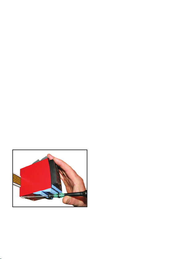
Billede 1:
Modulet frigøres fra power railen ved
at løfte i den nederste lås.
9202 - Product Version 9202-003 4
Page 7

EF-OVERENSSTEMMELSESERKLÆRING
Som producent erklærer
PR electronics A/S
Lerbakken 10
DK-8410 Rønde
hermed at følgende produkt:
Type: 9202
Navn: Pulse isolator
er i overensstemmelse med følgende direktiver og standarder:
EMC-direktivet 2004/108/EF og senere tilføjelser
EN 61326-1 : 2006
For specifikation af det acceptable EMC-niveau henvises til modulets
elektriske specifikationer.
Lavspændingsdirektivet 2006/95/EF og senere tilføjelser
EN 61010-1 : 2001
ATEX-direktivet 94/9/EF og senere tilføjelser
EN 60079-0 : 2009, EN 60079-11 : 2007, EN 60079-15 : 2005,
EN 60079-26 : 2007, EN 6124 1-11 : 2006
ATEX-certifikat: KEMA 07ATEX0146 X
Bemyndiget organ:
DEKRA Certification B.V. (0344)
Utrechtseweg 310, 6812 AR Arnhem
P.O. Box 5185, 6802 ED Arnhem
The Netherlands
Rønde, 7. februar 2012 Kim Rasmussen
Producentens underskrift
9202 - Product Version 9202-003 5
Page 8

PULSE ISOLATOR
9202
• Interface for NAMUR-følere og kontakter
• Udvidet autodiagnosticering og kabelfejlsdetektering
• 1 eller 2 kanaler
• Kan forsynes separat eller installeres på power rail,
PR type 9400
• SIL 2-certificeret via Full Assessment
Avancerede features
• Konfigurationogmonitoreringviaaftageligdisplayfront(PR4501).
• ValgafdirekteellerindirektefunktionforhverkanalviaPR4501.
• Avanceretmonitoreringafinternkommunikationoggemtedata.
• Mulighedforredundantforsyningviapowerrailog/ellerseparatforsyning.
• SIL2-funktionalitetenskalaktivttilvælgesviamenupunkt.
Anvendelse
• 9202kanmonteresisikkertområdesamtizone2/division2ogmodtage
signaler fra zone 0, 1, 2, 20, 21, 22 & M1 / Class I/II/III, Div. 1, Gr. A-G.
• ImpulsisolatortiloverførselafsignalerfraNAMUR-følereogmekaniskekontakter placeret i eksplosionsfarligt område til sikkert område.
• Overvågningaffejlsituationerogkabelbrudviadetindividuellestatusrelæog/
eller kollektivt elektronisk signal via power rail.
• 9202erkonstrueret,udvikletogcertificerettilbrugiSIL2-installationeriht.
kravene i IEC 61508.
Teknisk karakteristik
• 1grønog2gule/rødeLEDsifrontindikerernormaldriftogfunktionsfejl.
• 2,6kVACgalvaniskisolationmellemindgange/udgange/forsyning.
9202 - Product Version 9202-003 6
Page 9
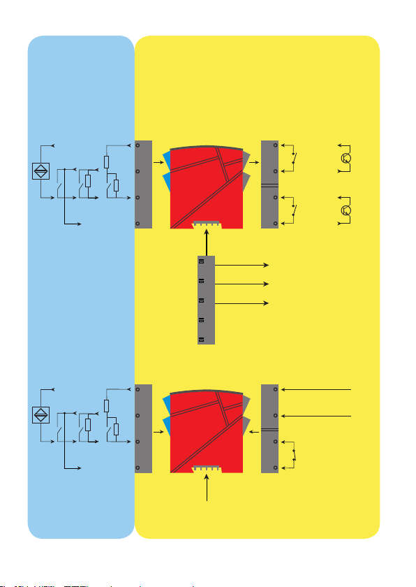
APPLIKATIONER
Gnd. -
Indgangssignaler:
Kanal 1:
NAMUR
+
-
Kanal 2:
NAMUR
+
-
Mekanisk
kontakt
R
R
p
Mekanisk
kontakt
R
R
p
Udgangssignaler:
Kanal 2:
N.O. eller
N.C.
Kanal 1:
N.O. eller
N.C.
Opto +
Kanal 2:
Opto -
Opto +
Kanal 1:
Opto -
Relæ
44
s
43
R
p
42
41
14
13
Relæ
Relæ
12
11
Relæ
Power rail
Statusrelæ-signal
Rail, +24 VDC
Rail, Gnd.
Forsyningsspændinger:
54
s
53
R
p
52
51
31
Forsyning +19,2...31,2 VDC
32
Modulstatus
33
N.C.
34
Modulstatus
Zone 0, 1, 2,
20, 21, 22, M1 &
Cl. I/II/III, div. 1
gr. A-G
Forsyning via
power rail
Zone 2 / Cl. 1, div. 2, gr. A-D eller sikkert område
9202 - Product Version 9202-003 7
Page 10
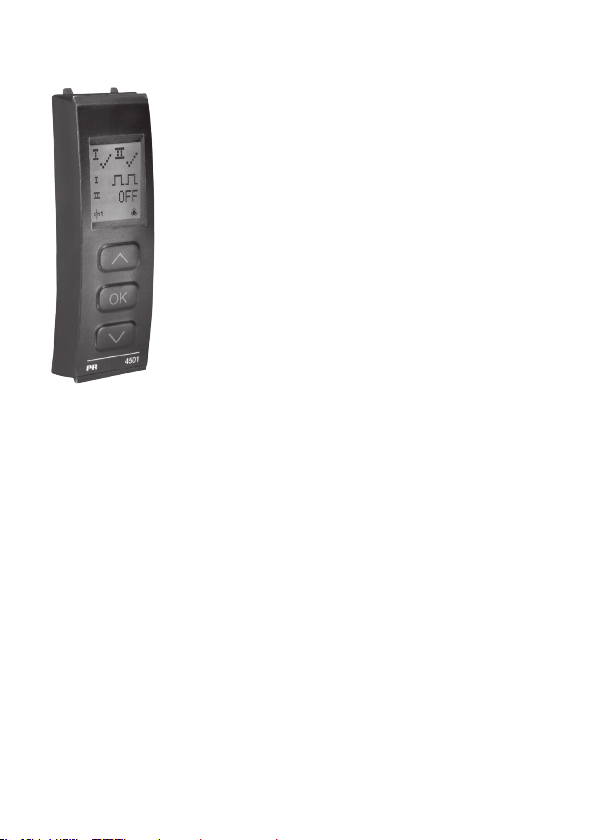
PR 4501 DISPLAY- / PROGRAMMERINGSFRONT
Funktionalitet
Den enkle menustruktur og de forklarende hjælpe tekster
leder dig automatisk gennem opsætningen og gør produktet
meget enkelt at anvende. Se beskrivelse af funktioner og
opsætningsmuligheder under afsnittet ”Programmering /
betjening af trykknapper”.
Anvendelse
• Kommunikationsinterfacetilændringafdriftsparametrei9202.
• Somfastmonteretdisplaytilvisualiseringafprocesdataogstatus.
Teknisk karakteristik
• FireliniersLCD-display,linie1(5,57mmhøj)viserhverkanalsstatus(OKeller
fejl). Linie 2 (3,33 mm høj) viser kanal 1’s udgang (ON / OFF), linie 3 (3,33 mm
høj) viser kanal 2’s udgang (ON / OFF) og linie 4 viser, om modulet er SIL-låst.
Statisk prik = SIL-låst og blinkende prik = ikke SIL-låst. Linie 4 viser også status for relæ 1 og relæ 2.
• Foratundgåuautoriseretbrugkankonfigurationenbeskyttesmedetpassword.
Montage / installation
• Klikkespåfrontenaf9202.
9202 - Product Version 9202-003 8
Page 11
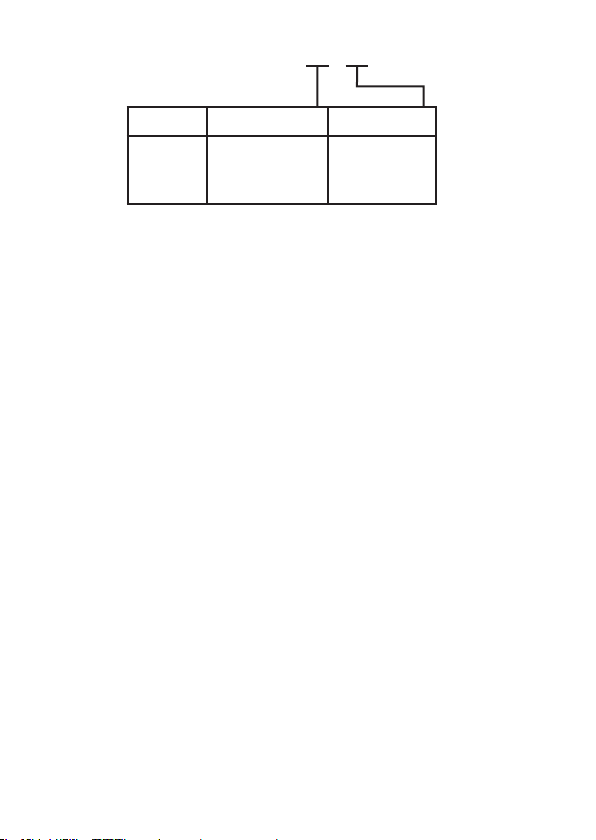
Bestillingsskema 9202B
Type Kontakt Kanaler
9202B Opto ...... : 1
Relæ N.O... : 2
Enkelt ... : A
Dobbelt.. : B
Relæ N.C...: 3
4501 = Display- / programmeringsfront
9400 = Power rail
Elektriske specifikationer
Specifikationsområde .................................. -20...+60°C
Lagringstemperatur ..................................... -20...+85°C
Fælles specifikationer:
Forsyningsspænding ................................... 19,2...31,2 VDC
Max. forbrug ................................................ ≤ 3 W (2 kanaler)
Sikring ......................................................... 400 mA T / 250 VAC
Isolationsspændinger, test / drift
Indgange / udgange / forsyning........... 2,6 kVAC / 300 VAC forstærket
Udgang 1 til udgang 2 ......................... 1,5 kVAC / 150 VAC forstærket
Statusrelæ til forsyning ........................ 1,5 kVAC / 150 VAC forstærket
Kommunikationsinterface ............................ Programmeringsfront 4501
Reaktionstid for kabelfejl ............................. < 200 ms
Kalibreringstemperatur ................................ 20...28°C
Hjælpespændinger:
NAMUR-forsyning ....................................... 8 VDC / 8 mA
Vibration, IEC 60068-2-6 ............................. Test Fc, 1 g, 2...100 Hz
Vibration vedvarende, IEC 60068-2-64 ....... Test Fh, 1 g, 3...100 Hz
Ledningskvadrat (min. / max.) ..................... 0,13...2,08 mm
flerkoret ledning
Klemskruetilspændingsmoment .................. 0,5 Nm
Relativ luftfugtighed .................................... < 95% RH (ikke kond.)
Mål, uden displayfront (HxBxD) .................. 109 x 23,5 x 104 mm
Mål, med displayfront (HxBxD) ................... 109 x 23,5 x 116 mm
Kapslingsklasse ........................................... IP20
Vægt ............................................................ 170 g / 185 g med 4501
2
/ AWG 26...14
9202 - Product Version 9202-003 9
Page 12

Indgange:
Følertyper:
NAMUR i henhold til ............................ EN 60947-5-6
Mekanisk kontakt med
serie- (R
R
R
Frekvensområde .......................................... 0...5 kHz
) og parallelmodstand Rp):
s
......................................................... Nom. 750 Ω
s
......................................................... Nom. 15 kΩ
p
Min. impulslængde ...................................... > 0,1 ms
Indgangsmodstand ..................................... Nom. 1 kΩ
Trig-niveau, signal ....................................... < 1,2 mA, > 2,1 mA
Trig-niveau, kabelfejl.................................... < 0,1 mA, > 6,5 mA
Udgange:
Relæudgange:
Statusrelæ:
Max. spænding .................................... 125 VAC / 110 VDC
Max. strøm ........................................... 0,5 A AC / 0,3 A DC
Max. effekt ........................................... 62,5 VA / 32W
Relæudgange:
Max. frekvens ....................................... 20 Hz
Max. spænding .................................... 250 VAC / 30 VDC
Max. strøm ........................................... 2 A AC / 2A DC
Max. effekt ........................................... 500 VA / 60 W
Opto, NPN-udgange:
Max. frekvens ....................................... 5 kHz
Min. impulslængde ............................... > 0,1 ms
Max. belastning, strøm / spænding ..... 80 mA / 30 VDC
Spændingsdrop ved 80 mA ................. < 2,5 VDC
Godkendelser:
EMC 2004/108/EF ....................................... EN 61326-1
LVD 2006/95/EF .......................................... EN 61010-1
UL, Standard for Safety .............................. UL 61010-1
GOST R
Marine:
Det Norske Veritas, Ships & Offshore ......... Stand. f. Certific. No. 2.4
I.S. / Ex:
ATEX 94/9/EF .............................................. KEMA 07ATEX0146 X
IECEx ........................................................... IECEx KEM 06.0039 X
c FM us ....................................................... 3034430-C
GOST Ex
9202 - Product Version 9202-003 10
Page 13

Funktionel sikkerhed:
SIL2 Certified & Fully Assessed iht. IEC 61508
Konfigurering af kabelfejlscheck
Modul: Konfiguration, fælles for begge kanaler Kabelfejlsdetektering:
9202
Indgang Hændelse Visning Grænse
Alle Kabelbrud CA.BR < 0,1 mA
Alle Kortsluttet kabel CA.SH > 6,5 mA
Kabelfejlscheck, detekteret og vist uafhængigt for hver kanal:
CA.BR = Yes eller CA.SH = Yes ON
Diagnosticering
Ellers: OFF
Kabelfejlsdetektering
Kabelfejlsdetektering (CA.BR, CA.SH):
9202 - Product Version 9202-003 11
Page 14

Hardware- / softwarefejl
Test af kommunikation mellem 4501 / 9202 NO.CO Fejl i stikforbindelse
EEprom-fejl - check konfiguration FL.ER
Hardwarefejl DE.ER
Hardwarefejl FC.ER
EEprom-fejl - check konfiguration CO.ER
Hardwarefejl CA.ER Fejl i fabrikskalibrering
Hardwarefejl HW.ER
Hardwarefejl OC.ER
Hardwarefejl MS.ER
Hardwarefejl MI.ER
Hardwarefejl MC.ER
! Alle fejlvisninger i display blinker 1 gang pr. sekund samt suppleres med tilhørende hjælpetekst.
Hvis fejlen er en kabelfejl, blinker displayets baggrundsbelysning også. Dette kan resettes ved tryk
på 3 tasten.
Fejl, som har indflydelse på begge kanaler, vises som kanal 1 fejl - og kanal 2’s linie er blank.
Hardwarefejl kan resettes på to måder. Man kan steppe gennem menuerne, f.eks. hvis den anden
kanal skal køre videre, eller slukke og tænde for modulet.
Fejlsøgning Visning Årsag
Visning ved hardwarefejl
Konfigurationsfejl eller crc-
mismatch, recovery-
konfiguration er indlæst
Ugyldig recovery-
konfiguration i modulet
Ugyldig kode-checksum
i 4501
Ugyldig konfiguration
(CRC eller data)
HW-setup -
konfigurations-mismatch
Kommunikationsfejl i pri-
mær processorkontrol
Primær intern forsyning
uden for grænser
Fejl i primær initialiserings-
selvtest
Fejl i primær flash eller
ram selvtest
FUNKTIONSBESKRIVELSE
Forbindelseseksempler på tilslutningstegning og blokdiagram (1)...(4)
(1) NAMUR-føler med kabelfejlsdetektering for brud og kortslutning.
(2) Mekanisk kontakt med kabelfejlsdetektering for brud og kortslutning, når Rs
og Rp er monteret på kontakten.
(3) Mekanisk kontakt med kabelfejlsdetektering for brud, når Rp er monteret på
kontakten.
(4) Mekanisk kontakt uden kabelfejlsdetektering.
9202 - Product Version 9202-003 12
Page 15
Power rail
forbindelser
91 92 93 94 95
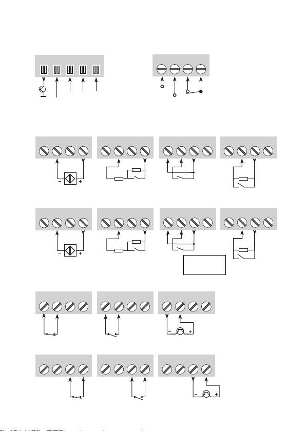
TILSLUTNINGER
Forsyning og
statusrelæ
31 32 33 34
Fejl
NC = ingen forbindelse
Kanal 1Kanal 2Kanal 1
Gnd.
+24 V
NAMUR-føler,
kabelfejl (1)
41 42 43 44
NAMUR-føler,
kabelfejl (1)
51 52 53 54
NCNC
Indgange:
Kontakt,
kabelfejl (2)
41 42 43 44
R
s
Kontakt,
kabelfejl (2)
51 52 53 54
R
s
R
p
R
p
Udgange:
Relæ, N.C. Opto, NPN
11 12 13 14
Relæ, N.C. Opto, NPNRelæ, N.O.
11 12 13 14
Relæ, N.O.
11 12 13 14
11 12 13 14
Gnd.
N.C.
+24 V
Kontakt,
ingen kabelfejl (4)
(1)...(4) = Se funktionsbeskrivelse på side 12
Kontakt,
kabelfejl, brud (3)
41 42 43 44 41 42 43 44
R
p
Kontakt,
ingen kabelfejl (4)
Kontakt,
kabelfejl, brud (3)
51 52 53 54 51 52 53 54
R
p
Rp = 15 kΩ
Rs = 750 Ω
11 12 13 14
11 12 13 14
Kanal 2
9202 - Product Version 9202-003 13
Page 16
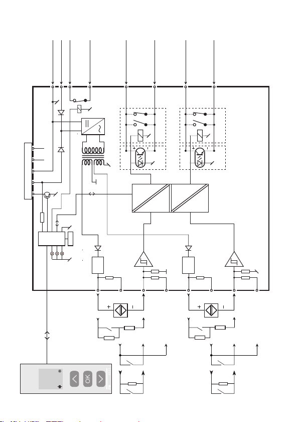
BLOKDIAGRAM
Forsyning +24 VDC
Gnd. -
31
323433
NC*NC*
Gnd.
+24 V
Power rail forbindelser
CPU
Modulstatus, Grøn
Kanal 1 status, Gul/Rød
Kanal 2 status, Gul/Rød
1
OF F
Statusrelæ N.C.
FLASH
Statusrelæ N.C.
Kanal 1
føler
NAMUR-
kabelfejl
Kontakt,
44
NAMUR
V
R
p
Opto + eller relæ N.O.
12
Kanal 1
43
eller relæ N.C.
s
R
p
R
42
Opto - eller relæ N.O.
eller relæ N.C.
11
(3) (4) (1)(2)
Kanal 2
9202B1 9202B2...B3
Kanal 2
41
Opto + eller relæ N.O.
14
54
føler
NAMUR-
kabelfejl
Kontakt,
= 15 kΩ
p
R
eller relæ N.C.
NAMUR
V
= 750 Ω
s
R
R
p
Opto - eller relæ N.O.
eller relæ N.C.
13
53
9202B1 9202B2...B3
52
s
R
p
R
51
(3) (4) (1)(2)
* NC = ingen forbindelse
9202
(1)...(4) = Se funktions-
beskrivelse på side 12
9202 - Product Version 9202-003 14
Page 17
Visning af signal- og kabelfejl uden displayfront
Power rail
signalstatus
N.C.
Statusrelæ,
Kanal 2:
Gul / rød
Kanal 1:
Gul / rød
Liste over LED- og fejlsignalvisninger
Tilstand Grøn LED
Modul OK Blinker Trukket OFF
Ingen forsyning OFF OFF OFF Sluppet ON
Modul defekt OFF Rød Rød Sluppet ON
Kanal 1, relæ trukket Blinker Gul Trukket OFF
Kanal 1, relæ sluppet ved kabelfejl Blinker Blinkende rød Sluppet ON (hvis aktiveret)
Kanal 1, relæ sluppet Blinker OFF Trukket OFF
Kanal 2, relæ trukket Blinker Gul Trukket OFF
Kanal 2, relæ sluppet ved kabelfejl Blinker Blinkende rød Sluppet ON (hvis aktiveret)
Kanal 2, relæ sluppet Blinker OFF Trukket OFF
9202 - Product Version 9202-003 15
Page 18

PROGRAMMERING /
BETJENING AF TRYKKNAPPER
Dokumentation til rutediagram
Generelt:
Når du skal konfigurere 9202, bliver du guidet igennem samtlige parametre og
kan vælge netop de indstillinger, der passer til applikationen. Til hver menu
findes en rullende hjælpetekst, som vises i displaylinie 3.
Konfigurationen udføres ved hjælp af de 3 taster:
1 forøger talværdien eller vælger næste parameter
2formindsker talværdien eller vælger forrige parameter
3accepterer valget og går til næste menu
Når konfigurationen er gennemført, returneres til normaltilstand 1.0.
Tryk og hold
uden at gemme de ændrede tal eller parametre.
Hvis ingen taster har været aktiveret i 1 minut, returnerer displayet til normal-
tilstand (1.0) uden at gemme de ændrede tal eller parametre.
Uddybende forklaringer:
Passwordbeskyttelse: Programmeringsadgang kan forhindres ved indkodning
af et password. Passwordet gemmes i impulsisolatoren, så sikkerheden
mod uønskede ændringer er så høj som muligt. Default password 2008 giver
adgang til alle programmeringsmenuer.
Kabelfejlsinformation via displayfront 4501
Kabelfejl (se grænser i skema) vises i display med CA.BR (Kabelbrud) eller
CA.SH (Kabel kortsluttet). Kabelfejl vises individuelt for hver kanal, men
konfigureres fælles for begge kanaler. Ved kabelfejl blinker displayets baggrundsbelysning. Dette kan resettes ved tryk på 3 tasten. Når kabelfejlen er
udbedret, vender modulet tilbage til normal drift.
3 tasten nede for at gå til forrige menu eller normaltilstand (1.0)
9202 - Product Version 9202-003 16
Page 19

Avancerede funktioner
Enheden giver adgang til en række avancerede funktioner, der nås ved at svare
”yes” til punktet ”adv.set”.
Display setup: Her kan man justere kontrast og baggrundsbelysning.
Opsætning af TAG-nummer med 5 alfanumeriske karakterer. Valg af funktionsvisning i linie 2 og 3 på displayet; der vælges mellem visning af digital
udgang eller visning af TAG-nummer. Vælges ”ALT” skifter displayet mellem
digital udgang og TAG-nummer.
Password: Her kan vælges et password mellem 0000 og 9999 til beskyttelse
mod uautoriserede ændringer. Enheden leveres default uden password.
Sprog: Der kan i menuen ”LANG” vælges mellem 7 forskellige sprogvarianter
af hjælpetekster, der fremkommer i menuen. Der kan vælges mellem UK, DE,
FR, IT, ES, SE og DK.
Power rail: I menuen ”RAIL” vælges om fejl på modulet skal overføres til en
central overvågning i PR 9410 power control unit.
Safety Integrity Level: Se Safety Manual for yderligere
information.
9202 - Product Version 9202-003 17
Page 20

RULLENDE HJÆLPETEKSTER I DISPLAYLINIE 3
[01]
Angiv korrekt password [ PASS ]
[02]
Gå til avanceret opsætningsmenu? [ ADV.SET ]
[03]
Aktiver fejldetektering for kortsluttet kabel? [ CA.SH ]
[04]
Vælg fejldetektering for afbrudt kabel? [ CA.BR ]
[05]
Aktiver overførsel af statussignal til power rail [ RAIL.ER ]
[06]
Gå til sprogvalg [ SETUP ]
[6/1]
Gå til password-indstilling [ SETUP ]
[6/2]
Gå til display opsætningsmenu [ SETUP ]
[6/3]
Gå til RAIL opsætningsmenu [ SETUP ]
[6/4]
Gå til SIL opsætningsmenu [ SETUP ]
[07]
Vælg Direkte signalbehandling [ CH1.FUN ] [CH2.FUN ]
Vælg Inverteret signalbehandling [ CH1.FUN ] [ CH2.FUN ]
[09]
Juster LCD-kontrast [ CONTRA ]
[10]
Juster LCD-baggrundsbelysning [ LIGHT ]
[11]
Angiv TAG-nr. på 5 karakterer [ ’TAGON ] [ ”TAGON ]
[12]
Udgangsbelastning vises i display [ DISP ]
Udgangsstatus vises i display
TAG-nr. vises i display
Vekslende information i display
[13]
Konfigurationens SIL-status (åben / låst) [ CONFIG ]
[14]
Aktiver SIL-lås af konfiguration? [ EN.SIL ]
[15]
Aktiver password-beskyttelse? [ EN.PASS ]
[16]
Angiv Nyt password [ NEW.PAS ]
[17]
Vælg sprog [ LANGUA ]
[18]
Kortsluttet kabel [ ICA.SH ] [ IIOFF ]
[19]
Afbrudt kabel [ ION ] [ IICA.BR ]
9202 - Product Version 9202-003 18
Page 21
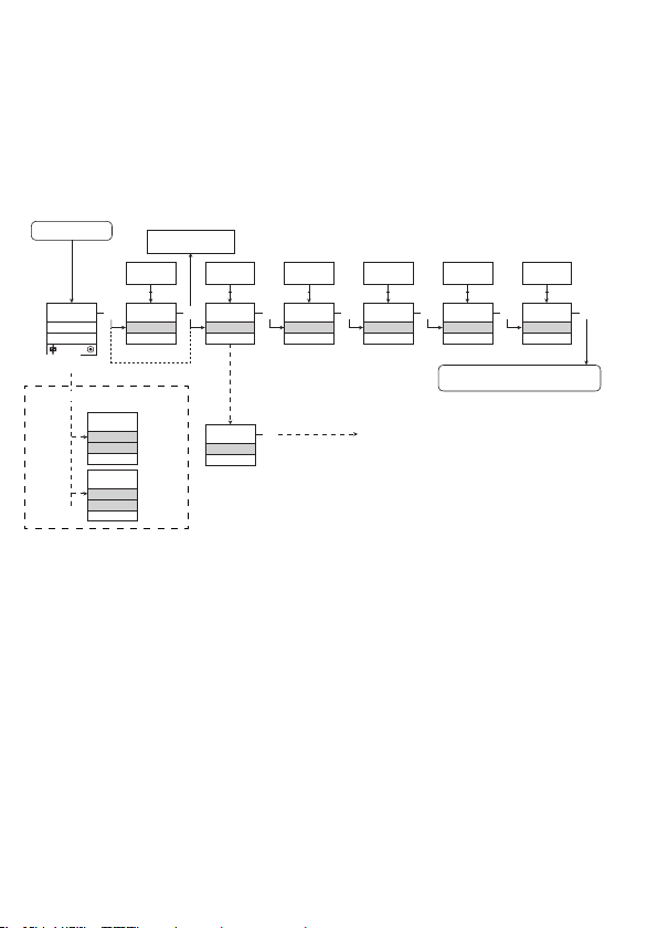
RUTEDIAGRAM
Hvis ingen taster har været aktiveret i 1 minut, returnerer displayet til normaltilstanden 1.0 uden at gemme eventuelle konfigurationsændringer.
1 Forøgelse af værdi / vælg næste parameter
2 Formindskelse af værdi / vælg forrige parameter
3 Accepter valget og gå til næste menu
Holde 3 går til forrige menu / returnerer til 1.0 uden at gemme
Power up
ON
OFF
1.0
Eksempler på fejlvisninger
CA.SH
OFF
Txt 18
ON
CA.BR
Txt 19
3
0000
1.1
direkte til [EN.SIL]
0000
9999
1 2
PASSW.
Txt 1
Hvis SIL-låst
3
NO
YES
1 2
NO
ADV.SET
Txt 2
YES
ADV.SET
Txt 2
3
3
1.0 = Normaltilstand.
Linie 1 viser status for kanal 1 og
kanal 2.
Linie 2 viser status for sensor 1.
Linie 3 viser status for sensor 2.
Linie 4 indikerer om modulet er
SIL-låst.
1.1 = Kun hvis beskyttet med password.
1.2 = Hvis password er valgt
Linie 1 symboler:
= OK. Blinkende = fejl.
Linie 2 og 3 symboler:
Indgangsfrekvens > 1 Hz =
.
Linie 4 symboler:
Statisk prik = SIL-låst.
Blinkende prik = ikke SIL-låst.
NO
YES
1 2
3
YES
CA.SH
Txt 3
YES
CA.BR
Txt 4
Fortsættes på siden
Rutediagram ADV.SET
Rød tekst viser safety parametre
i en SIL-konfiguration. Se Safety
Manual for yderligere information.
NO
YES
1 2
DIR
INV
1 2
3
DIR
CH1.FUN
Txt 7
3
Til normaltilstand 1.0
DIR
INV
1 2
DIR
CH2.FUN
Txt 7
3
9202 - Product Version 9202-003 19
Page 22
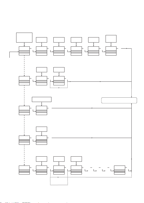
RUTEDIAGRAM,
AVANCEREDE INDSTILLINGER (ADV.SET)
DISP, PASS,
LANG, RAIL,
SIL
1 2
DISP
SETUP
Txt 6
PASS
SETUP
Txt 6/1
LANG
SETUP
Txt 6/2
RAIL
SETUP
Txt 6/3
SIL
SETUP
Txt 6/4
9
0
1 2
3
3
CONTRA
Txt 9
YES
NO
1 2
3 3
YES
EN.PASS
Txt 15
DE, DK, ES, FR,
IT, SE, UK
1 2
3
UK
LANGUA
Txt 17
YES
NO
1 2
3
YES
RAIL.ER
Txt 5
YES
NO
1 2
3
YES
EN.SIL
Txt 14
3
3
3
3
3
NEW.PAS
NO
2008
NEW.PAS
NO
1.2
9
0
1 2
9
LIGHT
Txt 10
9999
0000
1 2
0000
Txt 16
0000
9999
1 2
Txt 16
3
3
3
9
A
1 2
TAG1
TAGNO
Txt 11
LOCK
OPEN
1 2
LOCK
CONFIG
Txt 13
TAG
A.OUT
1 2
3
TAG2
TAGNO
Txt 11
3
3
Verificer SIL-konfiguration
3 3 3 3 3
. . . . . . . . . . . . . .
ALT
TAG
STAT
1 2
3
STAT
DISP
Txt 12
Til normaltilstand 1.0
SIL.OK
9202 - Product Version 9202-003 20
Page 23

APPENDIX
IECEx INSTALLATION DRAWING
ATEX INSTALLATION DRAWING
FM INSTALLATION DRAWING
SAFETY MANUAL
9202 - Product Version 9202-003 21
Page 24
[
LERBAKKEN 10, 8410 RØNDE DENMARK
For safe installation of 9202B the following must be observed. The module shall only be installed by
qualified personnel who are familiar with the national and international laws, directives and standards
that apply to this area.
Year of manufacture can be taken from the first two digits in the serial number.
For Installation in Zone 2 / Division 2 the following must be observed.
The 4501 programming module is to be used solely with PR electronics modules. It is important that
the module is undamaged and has not been altered or modified in any way. Only 4501 modules free
of dust and moisture shall be installed.
IECEx Certificate KEM 06.0039 X
Marking
Standards IEC60079-15 :2005, IEC60079-11:2011, IEC60079-0: 2011
IEC60079-26: 2006
Supply terminal (31,32)
Voltage: 19.2 – 31.2 VDC
Status Relay. terminal (33,34) Zone 2 Installation
Voltage max: 125VAC / 110VDC 32VAC / 32VDC
Power max: 62,5VA / 32W 16VA / 32W
Current max: 0.5A AC / 0.3ADC 0.5A AC / 1ADC
Installation notes.
Install in pollution degree 2, overvoltage category II as defined in IEC60664-1
Do not separate connectors when energized and an explosive gas mixture is present.
Do not mount or remove modules from the Power Rail when an explosive gas mixture is present.
Disconnect power before servicing.
The wiring of unused terminals is not allowed.
In type of protection [Ex ia Da] the parameters for intrinsic safety for gas group IIB are applicable.
For installation in Zone 2, the module shall be installed in an enclosure in type of protection Ex n or
Ex e, providing a degree of protection of at least IP54. Cable entry devices and blanking elements
shall fulfill the same requirements.
For installation on Power Rail in Zone 2, only Power Rail type 9400 supplied by Power Control Unit
type 9410 (Type Examination Certificate KEMA 07ATEX0152 X) is allowed.
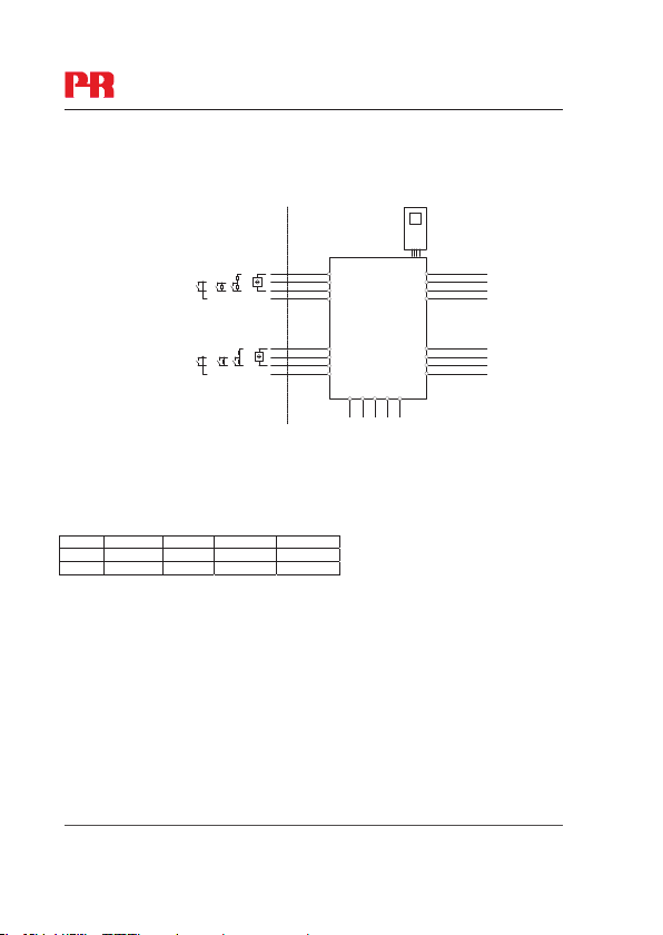
IECEx Installation drawing
[Ex ia Ga] IIC/IIB/IIA
Ex nA nC IIC T4 Gc
[Ex ia Da] IIIC
Ex ia Ma] I
9202QI01
Revision date:
2011-11-20
Version Revision
V4 R0
Prepared by:
PB
Page:
1/2
9202 - Product Version 9202-003 22
Page 25
LERBAKKEN 10, 8410 RØNDE DENMARK
Hazardous area Non Hazardous area
Zone 0,1, 2, 20, 21, 22 or Zone 2
Ex input:
CH1 (terminal 41,42,43,44)
CH2 (terminal 51,52,53,54)
U
:10.6 VDC
o
I
: 12 mADC
o
P
: 32 mW
o
Lo/Ro:1150 H/
IIC IIB IIA I
Co.
2.0 F 6.0 F 18 F
Lo. 260 mH 780 mH 1000 mH 1000 mH
Terminal CH1(11,12) CH2(13,14)
Digital output: NPN output:
Voltage max. 30 VDC
Current max. 80 mA
Terminal CH1(11,12) CH2(13,14)
Relay output: Non Hazardous location Zone 2 installation
Voltage max. 250 VAC / 30 VDC 32 V AC / 30 VDC
Power max. 500 VA / 60 W 64 VA / 60 W
Current max. 2 AAC / 2 ADC 2 AAC / 2 ADC
Revision date:
2011-11-20
Switch
Switch w. Shunt
Version Revision
Contact Sensor
V4 R0
-20 ≤ Ta ≤ 60ºC
NAMUR Sensor
CH1
+
44
43
-
42
41
CH2
+
54
53
-
52
51
91 92 93 94 95
Power
Rail
4501
34
33
32
31
14
13
12
11
9202
Um: 253 V max. 400 Hz
Supply / Output:
(terminal 11,12,13,14)
(terminal 31,32,33,34)
(terminal 91,92,93,94,95)
90 µF
Prepared by:
PB
9202QI01
Page:
2/2
9202 - Product Version 9202-003 23
Page 26
,
LERBAKKEN 10, 8410 RØNDE DENMARK
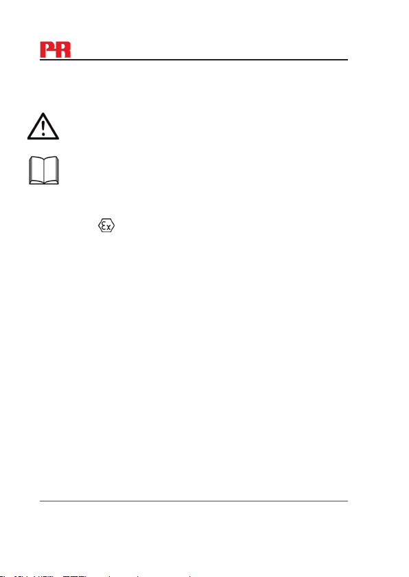
For sikker installation af 9202B skal følgende overholdes: Modulet må kun installeres af
kvalificerede personer, som er bekendt med national og international lovgivning, direktiver og
standarder i det land, hvor modulet skal installeres.
Produktionsår fremgår af de to første cifre i serienummeret
For installation i zone 2 / division 2 skal følgende overholdes:
Den aftagelige displayfront til programmering 4501 er udelukkende beregnet til brug på PR
electronics moduler. Det er vigtigt, at displayet er ubeskadiget, ikke ombygget eller på anden måde
forandret. 4501 må kun anvendes, hvis det er fri for støv og/eller fugt.
ATEX-certifikat KEMA 07 ATEX 0146 X
Mærkning
Standarder EN 60079-0 : 2009, EN 60079-11 : 2007, EN 60079-15 : 2005
EN 60079-26 : 2007, EN 61241-11 : 2006
Forsyningsklemme (31,32)
Spænding: 19,2 – 31,2 VDC
Statusrelæ, klemme (33,34) Zone 2-installation
Max. spænding: 125 VAC / 110 VDC 32 VAC / 32 VDC
Max. forbrug: 62,5 VA / 32 W 16 VA / 32 W
Max. strøm: 0
Installationsforskrifter:
Installer i forureningsgrad 2, overspændingskategori II som defineret i EN 60664-1.
Monter/demonter ikke stik, når forsyning er tilsluttet og der forefindes en eksplosionsfarlig
gasblanding.
Monter/demonter ikke modulet på Power Rail, når der forefindes en eksplosionsfarlig gasblanding.
Afbryd forsyning før udførelse af vedligehold og reparation.
Fortrådning i ubenyttede terminaler er ikke tilladt.
Ved beskyttelsesmetode [Ex ia Da] er parametrene for egensikkerhed for gasgruppe IIB
gældende.
For installation i zone 2 skal modulet installeres i et hus, som har beskyttelsestype Ex n eller Ex e,
og som giver en IP-beskyttelse på mindst IP54. Kabelforskruninger og blindstik skal opfylde
samme krav.
Ved installation på Power Rail type 9400 i zone 2 er det kun tilladt at forsyne Power Rail ved brug
af 9410 Power Control Unit (Type Examination Certificate KEMA 07ATEX0152 X).
Revision date:
2011-11-20
ATEX Installationstegning
II (1) G [Ex ia Ga] IIC/IIB/IIA
II 3G Ex nA nC IIC T4 Gc
I (1) D [Ex ia Da] IIIC
I (M1) [Ex ia Ma] I
5 A AC / 0,3 ADC 0,5A AC / 1 ADC
Version Revision
V4 R0 – DK01
Prepared by:
PB
9202QA01
Page:
1/2
9202 - Product Version 9202-003 24
Page 27
9202QA01
LERBAKKEN 10, 8410 RØNDE DENMARK
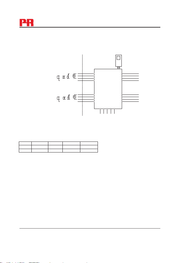
Ex-område Ikke Ex-område
Zone 0,1, 2, 20, 21, 22 eller zone 2
Uo:10,6 VDC
I
: 12 mADC
o
P
: 32 mW
o
Lo/Ro:1150 H/
IIC IIB IIA I
Co.
2,0 F 6,0 F 18 F
Lo. 260 mH 780 mH 000 mH 1000 mH
Ex-indgang:
Kanal 1 (klemme 41,42,43,44)
Kanal 2 (klemme 51,52,53,54)
Klemme. Kanal 1(11,12), kanal 2(13,14)
Digital udgang: NPN-udgang:
Max. spænding 30 VDC
Max. strøm 80 mA
Klemme, kanal 1(11,12), kanal 2(13,14)
Relæudgang: Ikke eksplosionsfarligt område Zone 2-installation
Max. spænding 250 VAC / 30 VDC 32 VAC / 30 VDC
Max. forbrug 500 VA / 60 W 64 VA / 60 W
Max. strøm 2 AAC / 2 ADC 2 AAC / 2 ADC
Switch
Switch w. Shunt
Contact Sensor
-20 ≤ Ta ≤ 60ºC
4501
NAMUR Sensor
CH1
+
-
+
-
CH2
90 µF
44
43
42
41
54
53
52
51
91 92 93 94 95
Power
34
33
32
31
14
13
12
11
9202
Rail
Um: 253 V max. 400 Hz
Forsyning / Udgang:
(klemme 11,12,13,14)
(klemme 31,32,33,34)
(klemme 91,92,93,94,95)
Revision date:
2011-11-20
Version Revision
V4 R0 – DK01
Prepared by:
PB
Page:
2/2
9202 - Product Version 9202-003 25
Page 28
(
)
LERBAKKEN 10, 8410 RØNDE DENMARK
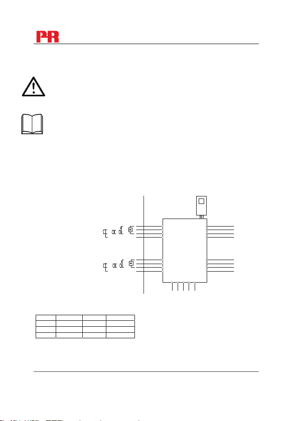
For safe installation of 9202B the following must be observed. The module shall only be
installed by qualified personnel who are familiar with the national and international laws,
directives and standards that apply to this area.
For Installation in Zone 2 / Division 2 the following must be observed.
The 4501 programming module is to be used solely with PR electronics modules. It is
important that the module is undamaged and has not been altered or modified in any way.
Only 4501 modules free of dust and moisture shall be installed.
c-FM-us Certificate 3034430
Hazardous area
Class I/II/III, Division 1, Group A,B,C,D,E,F,G
or Class I, Zone 0/1 Group IIC, [AEx ia] IIC or
or Class I, Zone 0/1 Group IIC, [Ex ia] IIC
Simple Apparatus or
Intrinsically safe apparatus
with entity parameters:
Vmax (Ui) ≥ Vt (Uo)
Imax (Ii) ≥ It (Io)
Pi ≥ Pt(Po)
Ca(Co) ≥ C
cable + Li
La(Lo) ≥ L
U
/ Vt: 10.6 V
o
I
/ Isc: 12 mA
o
P
: 32 mW
o/Pt
Lo/Ro La/Ra: 1150 H/
Group IIC IIB IIA
Group A,B C,E,F D,G
Co/Ca
2.0
Lo./La 260 mH 780 mH 1000 mH
Terminal CH1(44,42) CH2(54,52)
Revision date:
2011-11-20
FM Installation drawing
Switch
Switch w. Shunt
Contact Sensor
cable + Ci
F 6.0 F 18 F
Version Revision
V4 R0
Non Hazardous area or
Class I, Division 2, Group A,B,C,D T4
or Class I, Zone 2 Group IIC T4
-20 ≤ Ta ≤ 60ºC
NAMUR Sensor
CH1
+
44
43
-
42
41
CH2
+
54
53
-
52
51
91 92 93 94 95
Power
Rail
Prepared by:
4501
9202
Um: 253 V max. 400 Hz
Supply / Output
(terminal 11,12,13,14)
(terminal 31,32,33,34)
terminal 91,92,93,94,95
PB
9202QF01
34
33
32
31
14
13
12
11
Page:
1/2
9202 - Product Version 9202-003 26
Page 29

9202QF01
LERBAKKEN 10, 8410 RØNDE DENMARK
Terminal (31,32)
Supply:
Voltage 19.2 – 31.2 VDC
Power max. 3 W
Terminal (33,34)
Status Relay: Non Hazardous location: Division 2 or Zone 2 installation:
Voltage max. 125 VAC / 110 VDC 32 VAC / 32VDC
Power max. 62.5 VA / 32 W 16 VA / 32 W
Current max. 0.5 AAC / 0.3 ADC 0.5 AAC / 1 ADC
Terminal CH1(11,12) CH2(13,14)
Digital output: NPN output:
Voltage max. 30 VDC
Current max. 80 mA
Terminal CH1(11,12) CH2(13,14)
Relay output: Non Hazardous location: Division 2 or Zone 2 installation:
Voltage max. 250 VAC / 30VDC 32 VAC / 30VDC
Power max. 500 VA / 60W 64 VA / 60 W
Current max. 2 AAC / 2ADC 2 AAC / 2 ADC
Installation notes:
The installation and wiring shall be in accordance with the Canadian Electrical Code for Canada and
National Electrical Code NFPA 70, Article 500 or 505 for installation in USA.
The module must be supplied from a Power Supply having double or reinforced insulation.
The use of stranded wires is not permitted for mains wiring except when wires are fitted with cable
ends.
For installation on the 9400 Power Rail the power must be supplied from Power Control Module Unit
9410.
Install in pollution degree 2, overvoltage category II.
The module must be installed in an enclosure suitable for the environment for which it is used.
For installation in Zone 2 or Division 2, the module must be installed in a suitable outer enclosure
according to the regulations in the CEC for Canada or NEC for USA.
The module is galvanically isolated and does not require grounding.
Use 60 / 75 ºC copper conductors with wire size AWG: (26-14).
Warning: Substitution of components may impair intrinsic safety and / or suitability for Div. 2 / Zone 2.
Warning: To prevent ignition of explosive atmospheres, disconnect power before servicing and do not
separate connectors when energized and an explosive gas mixture is present.
Warning: Do not mount or remove modules from the Power Rail when an explosive gas mixture is
present.
Revision date:
2011-11-20
Version Revision
V4 R0
Prepared by:
PB
Page:
2/2
9202 - Product Version 9202-003 27
Page 30

SAFETY MANUAL
PULSE ISOLATOR
9202
This safety manual is valid for the following product versions:
Version No. V5R0
9202-002
9202-003
Page 31

9202 Pulse Isolator Safety Manual
0. CONTENTS
1. Observed standards ................................................................................ 2
2. Acronyms and abbreviations ................................................................... 2
3. Purpose of the product ........................................................................... 3
4. Assumptions and restrictions for use of the product.............................. 3
4.1 Basic safety specifications ............................................................. 3
4.2 Associated equipment .................................................................... 3
4.2.1 Relay output ........................................................................ 3
4.2.2 Opto output ......................................................................... 3
4.2.3 Field device ......................................................................... 3
4.3 Failure rates .................................................................................... 3
4.4 Safe parameterisation ..................................................................... 4
4.5 Installation in hazardous areas ....................................................... 4
5. Functional specification of the safety functions...................................... 4
6. Functional specification of the non-safety functions .............................. 4
7. Safety parameters ................................................................................... 4
8. Hardware and software configuration. .................................................... 5
9. Failure category ....................................................................................... 5
10. Periodic proof test procedure ................................................................. 5
11. Procedures to repair or replace the product ........................................... 5
12. Maintenance ............................................................................................ 5
13. Documentation for routing diagram ........................................................ 6
13.1 In general ........................................................................................ 6
13.2 Further explanations ....................................................................... 6
13.2.1 Password protection ........................................................... 6
13.2.2 Cable fault information via display front 4501 .................... 6
13.4 Advanced functions ........................................................................ 6
13.4.1 Display setup ...................................................................... 7
13.4.2 Password ............................................................................ 7
13.4.3 Language ............................................................................ 7
13.4.4 Power rail ............................................................................ 7
13.4.5 Safety integrity level ............................................................ 7
14 Safe parameterisation - user responsibility ............................................. 8
14.1 Safety-related configuration parameters ........................................ 8
14.2 Verification procedure ..................................................................... 8
14.2.1 If no password is set ........................................................... 8
14.2.2 If password is set ................................................................ 9
14.3 Functional test ................................................................................ 9
15 Fault reaction and restart condition ........................................................ 9
16 User interface .......................................................................................... 10
16.1 Scrolling help texts in display line 3 ............................................... 10
16.2 Routing diagram .............................................................................. 11
16.3 Routing diagram - Advanced settings (ADV.SET)........................... 12
17. Connections diagram ............................................................................. 13
Version No. V5R0 1
Page 32

Safety Manual 9202 Pulse Isolator
1. Observed standards
Standard Description
IEC 61508
IEC 61508-
2:2000
IEC 61508-
3:1998
IEC 61326-
3-1:2008
Functional Safety of electrical / electronic / programmable
electronic safety-related systems
Part 2: Requirements for electrical / electronic / programmable
electronic safety-related systems
Part 3: Software requirements
Immunity requirements for safety-related systems
2. Acronyms and abbreviations
Acronym /
Abbreviation
Element
PFD
PFH
SFF
SIF
SIL
Designation Description
Term defined by IEC 61508 as “part of a
subsystem comprising a single component
or any group of components that performs
one or more element safety functions”
Probability of
Failure on Demand
Probability of dan-
gerous Failure per
Hour
Safe Failure
Fraction
Safety Integrity
Function
Safety Integrity
Level
This is the likelihood of dangerous safety
function failures occurring on demand.
The term “Probability” is misleading, as IEC
61508 defines a Rate.
Safe Failure Fraction summarises the
fraction of failures which lead to a safe
state and the fraction of failures which will
be detected by diagnostic measures and
lead to a defined safety action.
Function that provides fault detection (to
ensure the necessary safety integrity for the
safety functions)
The international standard IEC 61508
specifies four discrete safety integrity levels
(SIL 1 to SIL 4). Each level corresponds to
a specific probability range regarding the
failure of a safety function.
2 Version No. V5R0
Page 33

9202 Pulse Isolator Safety Manual
3. Purpose of the product
Pulse isolator for transmission of signals to the safe area from NAMUR sensors
and mechanical switches installed in the hazardous area.
The module can be mounted in the safe area and in zone 2 / div. 2 and receive
signals from zone 0, 1, 2, 20, 21 and 22 / Class I/II/III, Div. 1, Gr. A-G.
Error events, including cable breakage, are monitored and signalled via the
individual status relay and/or a collective electronic signal via the power rail.
The 9202 has been designed, developed and certified for use in SIL 2 applications
according to the requirements of IEC 61508.
4. Assumptions and restrictions for use of the product
4.1 Basic safety specifications
Operational temperature range ............ -20...+60°C
Storage temperature range .................. -20...+85°C
Power supply type, min. ....................... Double or reinforced
Supply voltage ...................................... 19.2...31.2 VDC
Output pulse length, min. ..................... 40 ms
Mounting area ....................................... Zone 2 / Division 2 or safe area
Mounting environment .......................... Pollution degree 2 or better
4.2 Associated equipment
4.2.1 Relay output
The relay output shall only be connected to equiment which has
a current limiting function of 2 A.
4.2.2 Opto output
The opto output signals are fed to SIL 2 compliant inputs of a
safety PLC specified to receive a frequency of 5 kHz and a pulse
length down to 40 microseconds or the field device signal pulse
length minus 60 microseconds.
4.2.3 Field device
The field device must provide a minimum pulse length of 100
microseconds.
4.3 Failure rates
The basic failure rates from the Siemens standard SN 29500 are used
as the failure rate database.
Failure rates are constant, wear-out mechanisms are not included.
External power supply failure rates are not included.
Version No. V5R0 3
Page 34
Safety Manual 9202 Pulse Isolator
4.4 Safe parameterisation
The user is responsible for verifying the correctness of the configuration
parameters. (See section 14 Safe parameterisation - user responsibility).
Manual override may not be used for safety applications.
4.5 Installation in hazardous areas
The IECex Installation drawing, ATEX Installation drawing and FM
Installation drawing shall be followed if the products are installed in
hazardous areas.
5. Functional specification of the safety functions
Pulse isolator as well as supply of NAMUR sensors and mechanical switches with
cable error detection installed in the hazardous area. Cable error detection only
works with NAMUR sensors or with the use of external resistors Rs and Rp. See
connections diagram at page 13 (switch, cable fault) .
6. Functional specification of the non-safety functions
The status relay (terminal 33 and 34), error signal on power rail (terminal 91) and
LED outputs are not suitable for use in any Safety Instrumented Function.
7. Safety parameters
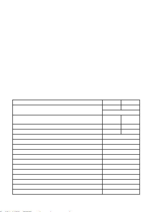
Probability of dangerous Failure per Hour (PFH) 4.66E-8 3.62E-8
Probability of failure on demand (PFD) -
1 year proof test interval
Proof test interval (10% of loop PFD) 4 years 5 years
Safe Failure Fraction 90% 91%
Demand response time, opto output
Demand response time, relay output
Demand mode High
Demand rate 1000 s
Mean Time To Repair (MTTR) 8 hours
Diagnostic test interval 10 seconds
Hardware Fault Tolerance (HFT) 0
Component Type B
SIL capability SIL 2
Description of the “Safe State”, opto output High impedance
Description of the “Safe State”, relay output De-energised
Relay lifetime (Note
2
) 100 000 times
Relay Opto
1
, Note2
Note
2.04E-4 1.58E-4
<125
µs
<10 m
s
4 Version No. V5R0
Page 35

9202 Pulse Isolator Safety Manual
Note1: The 9202 contains no lifetime limiting components, therefore the PFH
figures are valid for up to 12 years, according to IEC 61508.
2
: The maximum frequency for Pulse Isolator 9202 with relay output is 20 Hz.
Note
The user must calculate the product lifetime with regard to the relay lifetime.
8. Hardware and software configuration.
All configurations of software and hardware versions are fixed from factory, and
cannot be changed by end-user or reseller.
This manual only covers products labelled with the product version (or range of
versions) specified on the front page.
9. Failure category
Failure category
Fail Safe Detected 0.000E+00 0.000E+00
Fail Safe Undetected 2.897E-07 2.755E-07
Fail Dangerous Detected 1.303E-07 1.356E-07
Fail Dangerous Undetected 4.658E-08 3.618E-08
Failure rates (1/h)
Relay Opto
10. Periodic proof test procedure
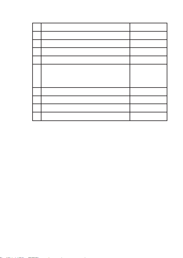
Step Action
1 Bypass the safety PLC or take other appropriate action to avoid a false trip
Connect a simulator identical to the input setup
2
Perform an ON / OFF signal for each channel
3
Observe whether the output channel acts as expected
4
Restore the input terminals to full operation
5
Remove the bypass from the safety PLC or otherwise restore normal operation
6
This test will detect approximately 95% of possible “du” (dangerous undetected)
failures in the pulse isolator. The proof test is equivalent to the functional test.
11. Procedures to repair or replace the product
Any failures that are detected and that compromise functional safety should be
reported to the sales department at PR electronics A/S.
Repair of the module and replacement of circuit breakers must be done by PR
electronics A/S only.
12. Maintenance
No maintenance required.
Version No. V5R0 5
Page 36

Safety Manual 9202 Pulse Isolator
13. Documentation for routing diagram
The routing diagram is shown in section 16.2.
13.1 In general
When configuring the 9202, you will be guided through all parameters
and you can choose the settings which fit the application. For each
menu there is a scrolling help text which is automatically shown in line
3 on the display.
Configuration is carried out by use of the 3 function keys:
1 will increase the numerical value or choose the next parameter
2will decrease the numerical value or choose the previous parameter
3will save the chosen value and proceed to the next menu
When configuration is completed, the display will return to the default
state 1.0.
Pressing and holding
default state (1.0) without saving the changed values or parameters.
If no key is activated for 1 minute, the display will return to the default
state (1.0) without saving the changed values or parameters.
13.2 Further explanations
13.2.1 Password protection
Access to the configuration can be blocked by assigning
a password. The password is saved in the module in order
to ensure a high degree of protection against unauthorised
modifications to the configuration. Default password 2008
allows access to all configuration menus.
Password protection is mandatory in SIL applications.
13.2.2 Cable fault information via display front 4501
Cable fault (see limits in the table) is displayed as CA.BR
(cable break) or CA.SH (cable short-circuited). Cable fault is
shown independently for each channel but the configuration is
common for both channels. In case of cable fault the backlight
flashes. This can be reset by pressing the
cable fault has been remedied, the module will return to normal
operation.
13.4 Advanced functions
The unit gives access to a number of advanced functions which can be
reached by answering “Yes” to the point “adv.set”.
3 will return to the previous menu or return to the
3 key. When the
6 Version No. V5R0
Page 37

9202 Pulse Isolator Safety Manual
13.4.1 Display setup
Here you can adjust the brightness contrast and the backlight.
Setup of tag numbers with 5 alphanumerics. Selection of
functional readout in line 2 and 3 of the display - choose between
readout of digital output or tag no. When selecting ”ALT” the
readout toggles between digital output and tag no.
13.4.2 Password
Here you can choose a password between 0000 and 9999 in
order to protect the unit against unauthorised modifications
to the configuration. The unit is delivered default without
password.
13.4.3 Language
In the menu ”LANG” you can choose between 7 different
language versions of help texts that will appear in the menu. You
can choose between UK, DE, FR, IT, ES, SE and DK.
13.4.4 Power rail
In the menu ”RAIL” you can choose if errors in the module are
transmitted to the central surveillance in the PR 9410 power
control unit.
13.4.5 Safety integrity level
See Safe parameterisation - user responsibility
Version No. V5R0 7
Page 38

Safety Manual 9202 Pulse Isolator
14 Safe parameterisation - user responsibility
14.1 Safety-related configuration parameters
Parameters Value Description
CH1.FUN DIR / INV Direct / inverted channel function
CH2.FUN. DIR / INV Direct / inverted channel function
PASSW 0 - 9999 New password
The above safety-related configuration parameters are marked in red
text in the routing diagrams and must be verified by the user in a SILconfiguration.
14.2 Verification procedure
The verification is done using the display / programming front PR 4501
by following the procedure described below.
14.2.1 If no password is set
Action Display shows
1 Press OK ADV.SET
2 Set (ADV.SET) to Yes and press OK DISP SETUP
3 Step down to (SIL SETUP) and press OK EN.SIL
4 Set (EN SIL) to YES and press OK NEW.PASS
5 Set password to a number between 0 and
9999 and press OK
(At this time the module starts operating
in SIL mode with the entered configuration
parameters!)
6 Verify Channel 1 function and press OK CH1.FUN
7 Verify Channel 2 function and press OK CH2:FUN
8 Verify password and press OK PASSW
9 Verify SIL and press OK
* Open is shown briefly in the display.
VerifyOPEN
”briefly”
LOCK*
8 Version No. V5R0
Page 39
9202 Pulse Isolator Safety Manual
14.2.2 If password is set
Action Display shows
1 Press OK PASSW
2 Enter password and press OK ADV.SET
3 Set (ADV.SET) to Yes and press OK DISP SETUP
4 Step down to (SIL SETUP) and press OK EN.SIL
5 Set (EN SIL) to YES and press OK
(At this time the module starts operating
in SIL mode with the entered configuration
parameters!)
6 Verify Channel 1 function and press OK CH1.FUN
7 Verify Channel 2 function and press OK CH2:FUN
8 Verify password and press OK PASSW
9 Verify SIL and press OK
VerifyOPEN
”briefly”
LOCK*
* Open is shown briefly in the display
14.3 Functional test
The user is responsible to make a functional test after verification of
safety parameters. The procedure for periodic proof test described in
section 10 shall be used.
15 Fault reaction and restart condition
When the 9202 detects a fault the output will go to Safe State, in which the opto
output will go to “high impedance” or the relay output will go to “de-energised”.
If the fault is application-specific (cable error detection) the 9202 will restart when
the fault has been corrected.
For device faults there are 2 ways of bringing the module out of Safe State.
1. Power cycle the module.
2. Bring the module out of SIL mode (choose “NO” in the menu point ”EN.SIL”),
and set it back to SIL mode again (choose “YES” in the menu point “EN.SIL” and
verify the configuration).
Version No. V5R0 9
Page 40

Safety Manual 9202 Pulse Isolator
16 User interface
16.1 Scrolling help texts in display line 3
Set correct password [ PASS ]
[01]
Enter advanced setup [ ADV.SET ]
[02]
Enable cable short circuit error indication [ CA.SH ]
[03]
Enable cable breakage error indication? [ CA.BR ]
[04]
Enable rail status signal output? [ RAIL.ER ]
[05]
Enter language setup [ SETUP ]
[06]
Enter password setup [ SETUP ]
[6/1]
Enter display setup [ SETUP ]
[6/2]
Enter rail setup [ SETUP ]
[6/3]
Enter SIL setup [ SETUP ]
[6/4]
Select direct channel function [ CH1.FUN ] [CH2.FUN ]
[07]
Select inverted channel function [ CH1.FUN ] [ CH2.FUN ]
Adjust LCD contrast [ CONTRA ]
[09]
Adjust LCD backlight [ LIGHT ]
[10]
Write a 5-character channel [ ’TAGON ] [ ”TAGON ]
[11]
Show output state in display [ DISP ]
[12]
Show TAG in display
Alternate shown information in display
Configuration SIL status (Open / Locked) [ CONFIG ]
[13]
Enable SIL configuration lock [ EN.SIL ]
[14]
Enable password protection [ EN.PASS ]
[15]
Set new password [ NEW.PAS ]
[16]
Select language [ LANGUA ]
[17]
Cable short circuit [ 1CA.SH ] [ 2OFF ]
[18]
Cable breakage [ 1ON ] [ 2CA.BR ]
[19
10 Version No. V5R0
Page 41
9202 Pulse Isolator Safety Manual
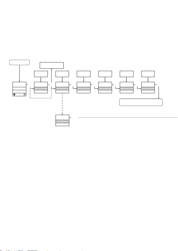
16.2 Routing diagram
If no key is activated for 1 minute, the display will return to the default
state 1.0 without saving configuration changes.
1 Increase value / choose next parameter
2 Decrease value / choose previous parameter
3 Save the chosen value and proceed to the next menu
Hold 3 Back to previous menu / return to menu 1.0 without saving
Power up
ON
OFF
1.0
3
0000
1.1
PASSW.
If SIL-locked
directly to [EN.SIL]
0000
9999
1 2
Txt 1
3
NO
YES
1 2
NO
ADV.SET
Txt 2
YES
ADV.SET
Txt 2
NO
YES
1 2
3
YES
CA.SH
Txt 3
3
1.0 = Default state
Line 1 shows status for channel 1 and
channel 2.
Line 2 shows status for sensor 1.
Line 3 shows status for sensor 2.
Line 4 indicates whether the module
is SIL-locked.
1.1 = Only if password-protected
1.2 = If password has been set.
Line 1 symbols:
= OK. Flashing = error
Line 2 and 3 symbols:
Input frequency > 1 Hz =
Line 4 symbols:
Static dot = SIL-locked
Flashing dot = not SIL-locked
NO
YES
1 2
3
YES
CA.BR
Txt 4
3
DIR
INV
1 2
DIR
CH1.FUN
Txt 7
3
To default state 1.0
Continued on the page
Routing diagram ADV.SET
DIR
INV
1 2
DIR
CH2.FUN
Txt 7
3
Version No. V5R0 11
Page 42
Safety Manual 9202 Pulse Isolator
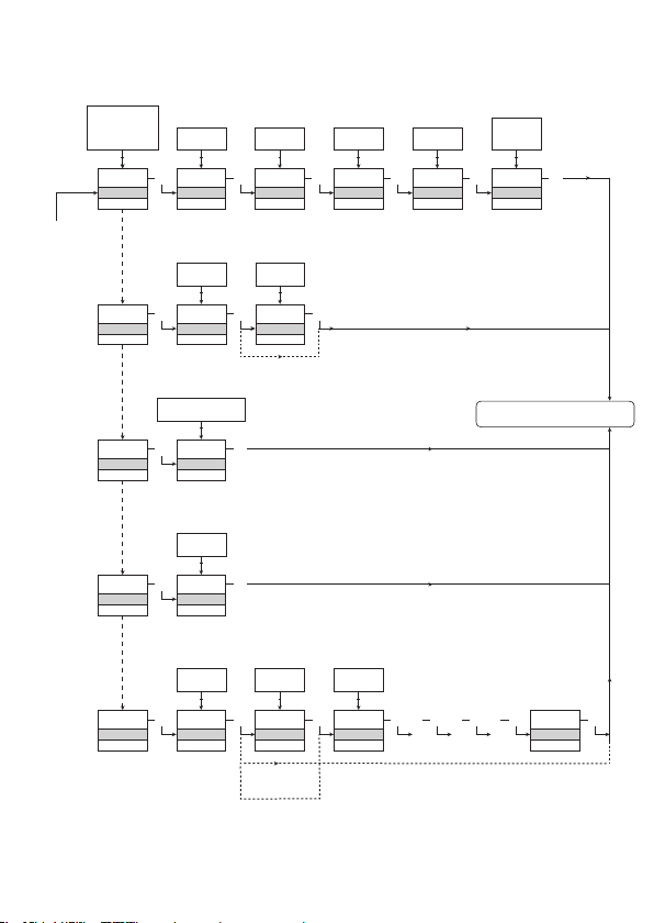
16.3 Routing diagram - Advanced settings (ADV.SET)
DISP, PASS,
LANG, RAIL,
SIL
1 2
DISP
SETUP
Txt 6
PASS
SETUP
Txt 6/1
LANG
SETUP
Txt 6/2
RAIL
SETUP
Txt 6/3
SIL
SETUP
Txt 6/4
9
0
1 2
3
3
CONTRA
Txt 9
YES
NO
1 2
3 3
YES
EN.PASS
Txt 15
DE, DK, ES, FR,
IT, SE, UK
1 2
3
UK
LANGUA
Txt 17
YES
NO
1 2
3
YES
RAIL.ER
Txt 5
YES
NO
1 2
3
YES
EN.SIL
Txt 14
3
3
3
3
3
NO
NO
1.2
9
0
1 2
9
LIGHT
Txt 10
9999
0000
1 2
0000
NEW.PAS
Txt 16
0000
9999
1 2
2008
NEW.PAS
Txt 16
3
3
3
9
A
1 2
TAG1
TAGNO
Txt 11
LOCK
OPEN
1 2
LOCK
CONFIG
Txt 13
TAG
A.OUT
1 2
3
TAG2
TAGNO
Txt 11
3
3
Verification of SIL configuration
3 3 3 3 3
. . . . . . . . . . . . . .
ALT
TAG
STAT
1 2
3
STAT
DISP
Txt 12
To default state 1.0
SIL.OK
12 Version No. V5R0
Page 43
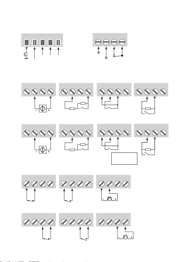
9202 Pulse Isolator Safety Manual
17. Connections diagram
Power rail
connections
91 92 93 94 95
Supply and
status relay
31 32 33 34
Error
NC = no connection
Channel 1Channel 2Channel 1
Gnd.
+24 V
NAMUR sensor,
cable fault
41 42 43 44
NAMUR sensor,
cable fault
51 52 53 54
NCNC
Switch,
cable fault
41 42 43 44
R
s
Switch,
cable fault
51 52 53 54
R
s
Inputs:
R
p
R
p
Outputs:
Relay, N.C. Opto, NPN
11 12 13 14
Relay, N.C. Opto, NPNRelay, N.O.
11 12 13 14
Relay, N.O.
11 12 13 14
11 12 13 14
Gnd.
N.C.
+24 V
Switch,
no cable fault
Switch,
no cable fault
41 42 43 44 41 42 43 44
R
p
Switch,
no cable fault
Switch,
no cable fault
51 52 53 54 51 52 53 54
R
p
Rp = 15 kΩ
Rs = 750 Ω
11 12 13 14
11 12 13 14
Channel 2
Version No. V5R0 13
Page 44
Displays
Programmable displays with a wide
selection of inputs and outputs for display of temperature,
volume and weight, etc. Feature linearisation, scaling,
and difference measurement functions for programming
via PReset software.
Ex interfaces
signals as well as HART
Interfaces for analogue and digital
®
signals between sensors / I/P
converters / frequency signals and control systems in Ex
zone 0, 1 & 2 and for some modules in zone 20, 21 & 22.
Isolation
digital signals as well as HART
Galvanic isolators for analogue and
®
signals. A wide product
range with both loop-powered and universal isolators
featuring linearisation, inversion, and scaling of output
signals.
Temperature
A wide selection of transmitters for DIN
form B mounting and DIN rail modules with analogue
and digital bus communication ranging from applicationspecic to universal transmitters.
Universal
PC or front programmable modules with
universal options for input, output and supply. This range
offers a number of advanced features such as process
calibration, linearisation and auto-diagnosis.
Page 45
www.prelectronics.fr
[email protected]
www.prelectronics.de
[email protected]
www.prelectronics.es
[email protected]
www.prelectronics.it
[email protected]
www.prelectronics.se
[email protected]
www.prelectronics.co.uk
[email protected]
www.prelectronics.com
[email protected]
www.prelectronics.cn
[email protected]
Head ofce
Denmark www.prelectronics.com
DK-8410 Rønde fax +45 86 37 30 85
 Loading...