

Page 1
PP Systems, Inc.
110 Haverhill Road, Suite 301
Amesbury, MA 01913 U.S.A.
Tel: +1 978 834-0505
Fax: +1 978 834-0545
CIRAS-2
Portable Photosynthesis System
Operator‟s Manual
Version 2.04
For Remote Control Software (RCS) Version 1.07 or greater.
© 2010 PP Systems. All Rights Reserved
12th May 2010
Email: [email protected]
Web Site: http://www.ppsystems.com
Page 2

This page is left intentionally blank.
Page 3
Table of Contents
Table of Contents
Table of Contents .......................................................................................................... 1
Preface ......................................................................................................................... 10
Notice ......................................................................................................................... 10
Documentation Conventions ...................................................................................... 10
User Registration........................................................................................................ 10
Service & Warranty .................................................................................................... 11
Contact Information .................................................................................................... 11
Unpacking Your Equipment ........................................................................................ 11
CIRAS-2 Essentials ..................................................................................................... 12
Before Powering On and Operating the System ........................................................ 12
Important Precautions ................................................................................................ 12
Getting Started ............................................................................................................ 13
Installing CIRAS-2 Remote Control Software on your computer ................................ 14
Avoiding UI-to-PC Communication Errors .................................................................. 14
Click ? at any time for On-line help .......................................................................... 17
Preparations for Use ................................................................................................... 18
Step 1. Insert 12V NiMH battery packs into main console ........................................ 18
Step 2. Connect CIRAS-2 power supply ................................................................... 18
Step 3. Make Leaf Cuvette electrical and gas connections ....................................... 19
CIRAS-2 gas/electrical connection panel – detailed view .................................................................... 19
Step 4. Connect leaf cuvette power cable to external 12V DC Power Supply .......... 20
Step 5. Inspect absorber columns and water vapor equilibrator ............................... 20
CIRAS-2 Console - Front Layout ......................................................................................................... 21
Step 6. Insert CO2 cartridge ...................................................................................... 21
CO2 Holder and Regulator Assembly ................................................................................................... 22
Step 7. Connect CIRAS-2/PC interface cable ........................................................... 22
Step 8. Power on CIRAS-2........................................................................................ 23
Step 9. Close the leaf cuvette ................................................................................... 24
Step 10. Start CIRAS-2 RCS program on your computer ......................................... 24
Familiarizing Yourself with the Measurement Display ............................................. 25
LED Tuning ................................................................................................................ 25
Gas Exchange Measurement Screen ........................................................................ 26
Data Display and Control Values ............................................................................... 26
Control Setpoints .................................................................................................................................. 26
Measured Parameters ......................................................................................................................... 27
Calculated Variables ............................................................................................................................ 27
Display Toggle ..................................................................................................................................... 27
Graph Display Options ............................................................................................... 28
Plot Type Toggle .................................................................................................................................. 28
Current Y Axis Variable ........................................................................................................................ 28
Status Bar .................................................................................................................. 28
Errors and Warnings ............................................................................................................................ 28
CIRAS-2 Status .................................................................................................................................... 28
CIRAS-2 Operator's Manual Version 2.04
- 1 -
Page 4

Table of Contents
CIRAS-2 Mode ..................................................................................................................................... 28
Power Status ........................................................................................................................................ 28
CIRAS-2 Power .................................................................................................................................... 29
Power Source ....................................................................................................................................... 29
Left and Right Battery Power Status .................................................................................................... 29
CIRAS RCS Menu Bar ................................................................................................. 30
File Menu ................................................................................................................... 30
Recalculate Data .................................................................................................................................. 30
Export Data .......................................................................................................................................... 30
View Diagnostics Report ...................................................................................................................... 30
Connections Menu ..................................................................................................... 30
Login .................................................................................................................................................... 30
Connect ................................................................................................................................................ 31
Disconnect ........................................................................................................................................... 31
Connect Add-On .................................................................................................................................. 31
Com Port .............................................................................................................................................. 31
Setup Menu ................................................................................................................ 31
Settings ................................................................................................................................................ 31
View Setup Details ............................................................................................................................... 32
Graphing .............................................................................................................................................. 32
Preferences ...................................................................................................................................... 32
Reset ................................................................................................................................................ 32
Utilities Menu .............................................................................................................. 32
Zero ...................................................................................................................................................... 32
Diff Bal.................................................................................................................................................. 33
Measure [Quit]...................................................................................................................................... 33
Initialise ................................................................................................................................................ 33
Pulse Alarm .......................................................................................................................................... 34
Simultaneous Measurements With CIRAS-2 and FMS2.................................................................. 34
Diagnostics........................................................................................................................................... 34
Stored Diff Bal ...................................................................................................................................... 35
Calibration ............................................................................................................................................ 35
Calibration Check ................................................................................................................................. 35
Calibration Reset .................................................................................................................................. 35
CO2 Midpoint ....................................................................................................................................... 35
Max C Determination ........................................................................................................................... 36
LED Tuning .......................................................................................................................................... 36
CIRAS Recording ................................................................................................................................. 36
Recording Menu ......................................................................................................... 36
Begin .................................................................................................................................................... 37
End ....................................................................................................................................................... 37
Start (Steady) ....................................................................................................................................... 37
Pause ................................................................................................................................................... 37
Single Record ....................................................................................................................................... 37
Multiple Record .................................................................................................................................... 38
Comment/Treatment ............................................................................................................................ 38
Response Level ................................................................................................................................... 38
Plugin Record ....................................................................................................................................... 38
View Menu ................................................................................................................. 38
Quick Info ............................................................................................................................................. 38
Update Parameters .............................................................................................................................. 39
Errors ................................................................................................................................................... 39
Warnings .............................................................................................................................................. 39
Time Plot .............................................................................................................................................. 39
CIRAS-2 Operator's Manual Version 2.04
- 2 -
Page 5

Table of Contents
Data Plot .............................................................................................................................................. 39
Battery Status ....................................................................................................................................... 39
Help Menu ................................ ................................ .................................................. 40
Help ...................................................................................................................................................... 40
About .................................................................................................................................................... 40
Diagnostics........................................................................................................................................... 40
Calibration & Stored Diff Bal ................................................................................................................ 40
Recording ............................................................................................................................................. 40
Closed Systems ................................................................................................................................... 40
Add-On Modules .................................................................................................................................. 40
About CIRAS ........................................................................................................................................ 40
System Setup and Operation ..................................................................................... 41
Set File Options ......................................................................................................... 41
Set Entry Name .................................................................................................................................... 41
Edit Entry Name ................................................................................................................................... 41
Add Entry ............................................................................................................................................. 42
Delete Entry ......................................................................................................................................... 42
Recording Options ............................................................................................................................... 42
Graphing Options ................................................................................................................................. 42
PRM File Options ....................................................................................................... 42
PRM Entry Name ................................................................................................................................. 42
Edit Entry Name ................................................................................................................................... 42
Add Entry ............................................................................................................................................. 42
Delete Entry ......................................................................................................................................... 43
Accessory ............................................................................................................................................. 43
Add Custom Accessory ........................................................................................................................ 44
Light Type ............................................................................................................................................ 45
Leaf Temperature (T
Leaf Temperature Determination: Explanations .................................................................................. 45
Energy Balance ................................................................................................................................ 45
Thermistor ........................................................................................................................................ 46
Direct Leaf Temperature Measurement - Common Problems ......................................................... 46
Infrared (IR) ...................................................................................................................................... 46
Leaf Area.............................................................................................................................................. 46
Boundary Layer Resistance ................................................................................................................. 47
Percent of Stomata on Upper Leaf Surface ......................................................................................... 47
Zero/Diff Bal Mode ............................................................................................................................... 47
Manual with Warnings ...................................................................................................................... 47
Automatic ......................................................................................................................................... 47
Auto Zero with Stored Diff Bal .......................................................................................................... 47
Manual Without Warnings ................................................................................................................ 47
Choice of Zero Mode – Recommendations ......................................................................................... 47
Changes in Zero Readings .................................................................................................................. 48
Analysis Flow ....................................................................................................................................... 49
Averaging Limit .................................................................................................................................... 49
) ....................................................................................................................... 45
leaf
System Setup ............................................................................................................. 49
Probe Type ........................................................................................................................................... 49
Air Supply On ................................................................................................................................... 49
Cuvette Flow ..................................................................................................................................... 49
Light Type [ _ ] ..................................................................................................................................... 49
PAR .................................................................................................................................................. 49
Energy Factor ................................................................................................................................... 49
Value ................................................................................................................................................ 49
Cuvette Environment .................................................................................................. 50
Control Types ....................................................................................................................................... 51
CIRAS-2 Operator's Manual Version 2.04
- 3 -
Page 6

Table of Contents
CO2 (0–2000 ppm) ........................................................................................................................... 51
1. Supply (Ref) Approximate ppm .................................................................................................... 51
2. Supply (Ref) Set ppm ................................................................................................................... 51
3. Cuvette (An) Set ppm ................................................................................................................... 51
About CO2 Control Types ..................................................................................................................... 51
H2O (0-100% or 0 mb-Dewpoint) ..................................................................................................... 51
1. Supply (Ref) % Ambient ............................................................................................................... 51
2. Supply (Ref) Set mb ..................................................................................................................... 51
3. Cuvette (An) % RH (vs. Leaf T) .................................................................................................... 51
4. Cuvette (An) Set mb (0-Dewpoint) ............................................................................................... 52
5. Leaf to Cuvette VPD ..................................................................................................................... 52
About H2O Control Types ..................................................................................................................... 52
Determination of Actual Ambient RH ................................................................................................ 52
PAR ...................................................................................................................................................... 52
Cuvette Flow ........................................................................................................................................ 52
Temperature ........................................................................................................................................ 53
Track Ambient .................................................................................................................................. 53
Entered Values ................................................................................................................................. 53
None ................................................................................................................................................. 53
Which Control Type Should I Use? ...................................................................................................... 53
If performing a Light Response: ....................................................................................................... 53
If performing a basic CO2 Response: ............................................................................................... 53
Customized Operation of CIRAS-2 with Ambient CO2 ......................................................................... 53
Customized Operation of CIRAS-2 at Humidity Levels Above Ambient .............................................. 54
CIRAS-2 Time ................................................................................................ ............ 54
Analog Outputs .......................................................................................................... 54
CO2 Analog Outputs ............................................................................................................................. 55
H2O Analog Outputs ............................................................................................................................. 55
Examples of Analog Outputs ............................................................................................................... 55
Automatically Update CIRAS ..................................................................................... 56
Graphing Preferences ................................................................................................. 57
Time Plot .................................................................................................................... 57
Select Variables ................................................................................................................................... 57
Font Size .............................................................................................................................................. 57
Time Plot Details .................................................................................................................................. 58
Select Variable to Edit .......................................................................................................................... 58
Time Span ............................................................................................................................................ 58
Data Plot .................................................................................................................... 58
Shown Variable on Y Axis .................................................................................................................... 58
Observing and Recording Leaf Gas Exchange ........................................................ 59
Checking the System with an Empty Cuvette............................................................. 59
Select Recording Options........................................................................................... 60
Treatment Editor .................................................................................................................................. 61
Treatment Groups ............................................................................................................................ 61
Treatment Items ............................................................................................................................... 61
Recording Mode ................................................................................................................................... 62
Placing the Leaf in the Cuvette .................................................................................. 63
Keypress Recording ................................................................................................... 65
Timed Recording ........................................................................................................ 66
Settle Time (Seconds) ......................................................................................................................... 67
Steady Pn Options ............................................................................................................................... 67
Use Steady Pn .................................................................................................................................. 67
Steady Pn Value ............................................................................................................................... 67
CIRAS-2 Operator's Manual Version 2.04
- 4 -
Page 7

Table of Contents
Recording at Pre-set Intervals ............................................................................................................. 67
Recording Block Options ..................................................................................................................... 67
Record Interval (seconds) ................................................................................................................ 67
Enable Recording Blocks ................................................................................................................. 68
Recording Blocks of Data at Pre-set Intervals ..................................................................................... 68
Suspending and Resuming Recording ................................................................................................ 68
Response Curve ........................................................................................................ 68
Editing Response Variable Values ....................................................................................................... 69
Editing All the Values in a Row ......................................................................................................... 69
Editing Groups of values .................................................................................................................. 70
Editing Individual values ................................................................................................................... 70
Enabling Levels ................................................................................................................................ 71
Recording Options ............................................................................................................................... 72
Repeat .............................................................................................................................................. 72
Interval .............................................................................................................................................. 72
Zero Settle Time ............................................................................................................................... 72
Steady Pn Options ............................................................................................................................ 73
Automatic Response ........................................................................................................................ 73
Manual Response............................................................................................................................. 73
PAR Type - Use Sensor ................................................................................................................... 73
CO2 Control Type ............................................................................................................................. 73
H2O Control Type ............................................................................................................................. 73
Light Type ......................................................................................................................................... 73
Temperature Control ........................................................................................................................ 73
Batch Response Curves............................................................................................. 76
Enable Batch Response Levels ........................................................................................................... 76
Batch Level Options ............................................................................................................................. 76
Show Prompt .................................................................................................................................... 76
Force Zero and Automatic Settle ...................................................................................................... 76
Repeat .............................................................................................................................................. 77
CIRAS Internal Recording .......................................................................................... 77
Enable Internal Recording .................................................................................................................... 78
Record Interval ..................................................................................................................................... 78
Apply Internal Recording ...................................................................................................................... 78
Transfer Data ....................................................................................................................................... 78
Clear CIRAS Memory ........................................................................................................................... 78
Stored Diff Bal ............................................................................................................ 78
Recalculate Data ......................................................................................................... 81
Processing Options .................................................................................................... 82
Recalculation Values .................................................................................................. 83
Information ........................................................................................................................................... 83
Options ................................................................................................................................................. 87
Load output File in Spreadsheet ....................................................................................................... 88
Load output File in Named Program ................................................................................................ 88
Export Data .......................................................................................................................................... 88
Options ............................................................................................................................................. 88
Include File Information .................................................................................................................... 89
Export Fields..................................................................................................................................... 89
Options ............................................................................................................................................. 90
Transferring Data From CIRAS-2 to Your Computer ................................................ 91
PCMCIA Card ...................................................................................................................................... 91
RS232 (Null Modem) Connection ........................................................................................................ 91
Establishing An ActiveSync Connection For Data Transfer from UI To PC ..................................... 91
CIRAS-2 Operator's Manual Version 2.04
- 5 -
Page 8

Table of Contents
ActiveSync® Communications Software .................................................................... 92
For Customers That Are Using The Integral PC (Pencentra) .............................................................. 93
For Customers That Are Using Our User Interface (UI) ...................................................................... 93
USB Connection ............................................................................................................................... 93
Installation of USB Drivers On Your PC ........................................................................................... 93
Establishing An ActiveSync Connection For Data Transfer from UI To PC ..................................... 94
Shutting Down the CIRAS-2 System .......................................................................... 95
Measuring Chlorophyll Fluorescence with the CFM ................................................ 96
Getting Started with the CFM ..................................................................................... 96
Firmware & Software Requirements .......................................................................... 96
Software Installation ............................................................................................................................. 96
Power Requirements .................................................................................................. 97
Leaf Cuvette Window ................................................................................................. 97
Replacing Cuvette Window .................................................................................................................. 97
Connecting the CFM to CIRAS-2 ............................................................................... 98
Operation from External PC ................................................................................................................. 99
Stand-Alone Operation (User Interface) ............................................................................................ 100
CFM Operation .......................................................................................................... 101
Default Adaptation .................................................................................................... 102
Dark Adaptation ................................................................................................................................. 102
Far Red Adaptation ............................................................................................................................ 102
No Adaptation .................................................................................................................................... 102
CFM Recording Options ........................................................................................... 102
Dark Period (Minutes) ........................................................................................................................ 103
Prompt when „expired‟........................................................................................................................ 103
After Dark Adaptation, perform .......................................................................................................... 103
CFM Setup ......................................................................................................................................... 104
Recovery Period (seconds) ................................................................................................................ 104
If Batch Response, Dark Adapt for each level ................................................................................... 104
When a CIRAS Record is taken, perform .......................................................................................... 105
If Response Curve, at end of level, perform ...................................................................................... 105
Complete CFM Recording with .......................................................................................................... 105
Save Trace Data ................................................................................................................................ 105
Include „Pre‟ and „Post‟ Data .............................................................................................................. 105
Calculation Options .................................................................................................. 105
Modulation Beam ..................................................................................................... 105
Enable Modulating Beam ................................................................................................................... 106
Mod. Level .......................................................................................................................................... 106
Gain .................................................................................................................................................... 106
Perform CFM Tuning ......................................................................................................................... 106
CFM Graphing Options ............................................................................................ 107
CFM Time Plot ................................................................................................................................... 107
CFM Data Plot .................................................................................................................................... 107
CIRAS-CFM Display ................................................................................................... 108
Recd. ........................................................................................................................ 108
CFM Display Buttons ................................................................................................ 109
CFM Tuning ............................................................................................................. 109
Recording Chlorophyll Fluorescence ...................................................................... 111
Keypress Recording with CFM ................................................................................. 111
CIRAS-2 Operator's Manual Version 2.04
- 6 -
Page 9

Table of Contents
Response Curve Recording with CFM ..................................................................... 115
CFM Output .............................................................................................................. 117
Calculation Error Codes ........................................................................................... 118
Brief Introduction to Chlorophyll Fluorescence ..................................................... 119
What is chlorophyll fluorescence? ............................................................................ 119
Techniques for Measuring Chlorophyll Fluorescence. ............................................. 120
Common Fluorescence Measurements ................................................................... 122
1. Fluorescence Induction Analysis (Kautsky Curve). ........................................................................ 122
2. Quantum Efficiency of Photosystem II ........................................................................................... 124
Glossary of Fluorescence Terms ............................................................................. 125
Measuring Soil Respiration with CIRAS-2 ............................................................... 127
Soil Respiration Measurement Display .................................................................... 127
Prompt ............................................................................................................................................... 127
Parameters ........................................................................................................................................ 127
Settings .............................................................................................................................................. 128
Soil Respiration Operational Settings ....................................................................... 128
Chamber Properties ........................................................................................................................... 129
Volume (cm3) .................................................................................................................................. 129
Area (cm2) ...................................................................................................................................... 129
System Type ................................................................................................................................... 129
Recording Parameters ....................................................................................................................... 129
CO2 Change ................................................................................................................................... 129
Maximum Time ............................................................................................................................... 129
System Temperature ...................................................................................................................... 129
Results............................................................................................................................................ 130
Data File ............................................................................................................................................. 130
Select File Mode ............................................................................................................................. 130
Treatment ........................................................................................................................................... 130
New Measurement ............................................................................................................................. 130
Graphing Options ............................................................................................................................... 130
Recording in Soil Respiration Mode ......................................................................... 131
Diagnostics ................................................................ ................................................ 133
Analyser A/D Reads ................................................................................................. 133
Analyser Temperature (oC) ................................................................................................................ 134
Atmospheric Pressure (mb) ............................................................................................................... 134
Pressure Difference (mb) ................................................................................................................... 134
Stored Zeros ...................................................................................................................................... 134
Reset Stored Zeros ............................................................................................................................ 134
CO2 Reference ................................................................................................................................... 134
CO2 Analysis ...................................................................................................................................... 134
H2O Reference ................................................................................................................................... 134
H2O Analysis ...................................................................................................................................... 134
Valve Settings .................................................................................................................................... 134
Apply valves to Zero ....................................................................................................................... 134
Apply valves to Measure ................................................................................................................ 135
Apply valves to Diff/Bal ................................................................................................................... 135
Flows .................................................................................................................................................. 135
Reference ....................................................................................................................................... 135
Analysis .......................................................................................................................................... 135
Log An/Ref...................................................................................................................................... 135
Temperature & PLC State ........................................................................................ 135
CIRAS-2 Operator's Manual Version 2.04
- 7 -
Page 10

Table of Contents
Temperature (oC) ............................................................................................................................... 135
Ambient .......................................................................................................................................... 135
Blender ........................................................................................................................................... 135
Cuvette Air ...................................................................................................................................... 136
Leaf/Sensor Base ........................................................................................................................... 136
Radiation Sensor ................................................................................................................................ 136
Cuvette State ..................................................................................................................................... 136
Probe .................................................................................................................................................. 136
Apply… ............................................................................................................................................... 137
Flows ........................................................................................................................ 137
Control [D/A] ....................................................................................................................................... 137
Analyser Flows ................................................................................................................................... 137
Apply Analyser Flow Control .............................................................................................................. 138
Cuvette Air Supply.............................................................................................................................. 138
Forwarding Flow [A/D] / Cuvette Flow [A/D] ................................................................................... 138
Flow (mls/min) ................................................................................................................................ 138
Flow Requested .............................................................................................................................. 138
Flow Measured ............................................................................................................................... 138
Control Setting ................................................................................................................................ 138
Auto Cuvette ............................................................................................................ 138
Light Control ....................................................................................................................................... 138
Temperature Control .......................................................................................................................... 139
Apply Lamp 1 LEDs ........................................................................................................................... 139
Batteries & Voltages ................................................................................................. 139
Board Voltage .................................................................................................................................... 139
Cuvette Voltage .................................................................................................................................. 139
Left Battery Voltage ............................................................................................................................ 139
Right Battery Voltage ......................................................................................................................... 140
Current Battery/Power Source ........................................................................................................... 140
Report ...................................................................................................................... 140
Quick Report ...................................................................................................................................... 140
Extended Report ................................................................................................................................ 140
Calibration ................................................................................................................. 143
External connections for CO2 Calibrations ............................................................... 143
CO2 calibrations using the internal standard ...................................................................................... 143
CO2 calibrations using a gas cylinder ................................................................................................ 143
H2O Calibration sources and connections ................................................................ 144
PP Systems‟ Water Vapor Calibrator ................................................................................................. 144
Performing Calibrations ............................................................................................ 145
Calibration Check ..................................................................................................... 145
Calibration Reset ...................................................................................................... 147
CO2 Midpoint ........................................................................................................... 147
Gas Connections for CO2 Midpoint .................................................................................................... 147
Max C Determination................................................................................................ 149
Appendix 1. Cuvettes and Probes .......................................................................... 151
Identification of Leaf Cuvette Types ......................................................................... 151
Leaf Cuvettes fitted with a FLAT GLASS WINDOW .......................................................................... 151
Leaf Cuvettes fitted with a PLASTIC HEMI-CYLINDER .................................................................... 151
CIRAS-2 Settings for Leaf Cuvettes and Probes ..................................................... 152
Appendix 2. CIRAS-2 Consumables and Spares ................................................... 153
Appendix 3. Photosynthesis Equations Used in CIRAS-2 ................................ .... 155
CIRAS-2 Operator's Manual Version 2.04
- 8 -
Page 11

Table of Contents
Calculations .............................................................................................................. 155
Step 1.0 .............................................................................................................................................. 155
Step 2.0 .............................................................................................................................................. 155
Step 3.0 .............................................................................................................................................. 156
Step 4.0 .............................................................................................................................................. 157
Step 5.0 .............................................................................................................................................. 158
Step 6.0 .............................................................................................................................................. 158
Symbol Definitions ................................................................................................... 159
Measured Parameters ....................................................................................................................... 159
Calculated Parameters ...................................................................................................................... 159
Physical Constants Used in Equations ..................................................................... 160
Saturated Vapor Pressure of Water from Air Temperature ...................................... 160
References ............................................................................................................... 161
Addendum .................................................................................................................. 162
Corrections to Stomatal Resistance Measurements for Differing Transpiration Rates
from Upper and Lower Leaf Surfaces ...................................................................... 162
Magnitude of Errors in RS ........................................................................................ 164
User Notes ................................................................................................................. 165
CIRAS-2 Operator's Manual Version 2.04
- 9 -
Page 12

Preface –
Preface
Notice
This equipment must not be used in situations where its failure could result in injury or death.
For applications where failure of this equipment to function correctly would lead to consequential damage,
the equipment must be checked for correct operation and calibration at intervals appropriate to the
criticality of the situation.
PP Systems' equipment warranty is limited to replacement of defective components, and does not cover
injury to persons or property or other consequential damage.
This manual is provided to help you install and operate the equipment. Every effort has been made to
ensure that the information contained in this manual is accurate and complete. PP Systems does not
accept any liability for losses or damages resulting from the use of this information.
It is extremely important that you take the time to review this information prior to installation and operation
of the equipment. Otherwise, damage may be caused which is not covered under our normal warranty
policy.
This manual and the information contained within are copyright to PP Systems. No part of the manual may
be copied, stored, transmitted or reproduced in any way or by any means including, but not limited to,
photocopying, photography, magnetic or other mechanical or electrical means, without the prior written
consent of PP Systems.
Windows and Excel are registered trademarks of Microsoft.
Quattro Pro is a registered trademark of Borland
Lotus 1-2-3 is a registered trademark of Lotus.
MS-DOS is a registered trademark of IBM.
Documentation Conventions
If viewed electronically, text marked blue acts as Hyperlinks.
User Registration
It is very important that ALL new customers register themselves with us to ensure that our user‟s list is
kept up-to-date. If you are a PP Systems‟ user, please register yourself electronically on our web site at:
http://www.ppsystems.com/user_registration2.htm
Only REGISTERED users will be allowed access to the protected “Users” section of our web site. This
section will contain important product information including hardware/software updates, application notes,
newsletters, etc.
Thank you in advance for your cooperation.
CIRAS-2 Operator's Manual Version 2.04
- 10 -
Page 13

–
Service & Warranty
PP Systems' equipment warranty is limited to replacement of defective components, and does not cover
injury to persons or property or other consequential damage.
The equipment is covered under warranty for one complete year, parts and labour included. This, of
course, is provided that the equipment is properly installed, operated and maintained in accordance with
written instructions (i.e. Operator's Manual).
The warranty excludes all defects in equipment caused by incorrect installation, operation or
maintenance, misuse, alteration, and/or accident.
If for some reason, a fault is covered under warranty, it is the responsibility of the customer to return the
goods to PP Systems or an authorised agent for repair or replacement of the defective part(s).
Contact Information
PP Systems, Inc.
110 Haverhill Rd, Suite 301
Amesbury, MA 01913 USA
Tel: 978-834-0505
Fax: 978-834-0545
Unpacking Your Equipment
It is extremely important that you check the contents of your equipment immediately upon receipt to
ensure that your order is complete and that it has arrived safely. Please refer to the checklist supplied (if
applicable) for a detailed list of spares and accessories that are included with your order.
DO NOT DISCARD ANY OF THE PACKAGING MATERIAL UNTIL ALL OF THE ITEMS LISTED ARE
ACCOUNTED FOR.
WE RECOMMEND THAT YOU RETAIN THE ORIGINAL PACKING FOR FUTURE USE.
If you suspect that any of the items listed on the appropriate checklist are not included or damaged, you
must contact PP Systems or authorized distributor immediately.
CIRAS-2 Operator's Manual Version 2.04
- 11 -
Page 14
CIRAS-2 Essentials –
!!! WARNING !!!
USE ONLY POWER SUPPLIES AND BATTERY CHARGERS SUPPLIED BY
PP SYSTEMS FOR THE CIRAS-2.
USE OF ANY OTHERS WILL INVALIDATE THE WARRANTY.
CIRAS-2 Essentials
Please observe the following to ensure correct operation of and avoid damage to CIRAS-2:
Before Powering On and Operating the System
Charge all 12V NiMH batteries prior to making measurements.
Charge each 12V NiMH battery independently using the chargers supplied by PP Systems.
Use only the power supply supplied by PP Systems for powering the CIRAS-2 externally.
Ensure that the probe (i.e. leaf cuvette) electrical connector is properly connected to CIRAS-2
before switching on power.
Be sure that the reference and analysis gas fittings are correctly connected to the proper gas
ports.
Check that the chemicals contained in the absorber columns are fresh.
Check that i) all absorber columns and ii) the water vapour equilibrator are properly seated in their
correct manifold positions.
Check for pinched or rolled “O” rings in the top and bottom caps of the absorber columns.
Close the leaf cuvette to allow successful LED tuning.
Always operate CIRAS-2 in a vertical position.
Important Precautions
Do not use substitute battery chargers or power supplies with CIRAS-2.
Avoid allowing water into any CIRAS-2 gas inlets or the leaf chamber. Do not use on wet foliage
or attempt to humidify the gas stream by direct artificial introduction of humidified air.
If there is any risk of water entering or condensing inside CIRAS-2, water dropout traps must be
fitted.
External filtration may be required in extremely dirty/dusty atmospheres.
Do not attempt to change the CO2 cartridge until at least 24 hours have elapsed since inserting
the cartridge in the CO2 regulator assembly.
To prevent voltage spikes and software conflicts avoid attaching/detaching probe (i.e. leaf cuvette)
electrical connections while CIRAS-2 is powered on.
Avoid powering off CIRAS-2 before completely exiting the RCS program.
CIRAS-2 Operator's Manual Version 2.04
- 12 -
Page 15
Getting Started –
Getting Started
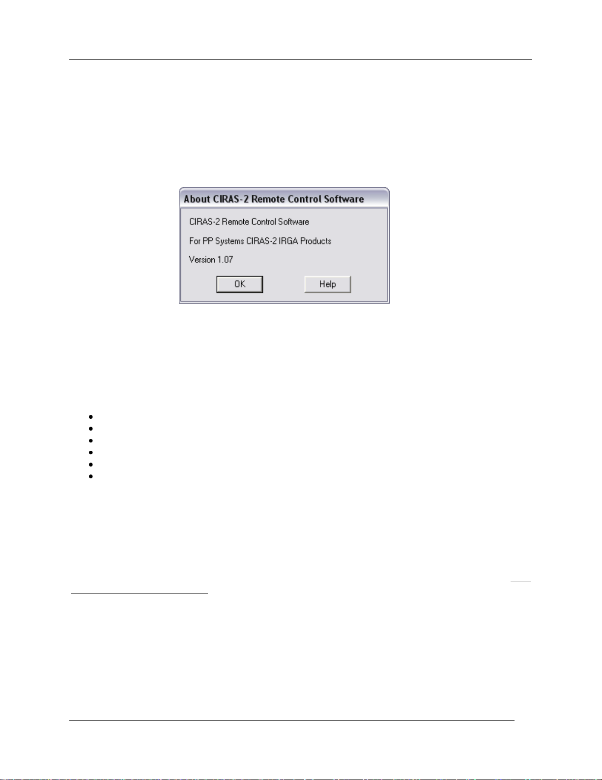
The CIRAS-2 Operator‟s Manual is designed to assist users running remote control software (RCS) v.
1.07 or greater. If the instructions and figures in this Operation Manual do not appear similar to your
CIRAS-2 system click Help – About in the RCS menu bar to view which software version you currently
have installed on your system. RCS v. 1.07 will be available for upgrade through the Registered Users
Area of our website: http://www.ppsystems.com/user_registration2.htm
At this point we expect that you have completed the CIRAS-2 Tutorial - the Tutorial is a condensed version
of the Operator‟s Manual and intended to quickly familiarize you with making basic leaf gas exchange
measurements. IF YOU HAVE NOT YET READ AND WORKED THROUGH THE TUTORIAL PLEASE
DO SO NOW, BEFORE CONTINUING.
A Technical Manual is available to all registered users as well. The CIRAS-2 Technical Manual
discusses topics such as:
Electrical and Pneumatic Connections
Gas Circuit and Flow Diagrams
Desiccants
Troubleshooting and Servicing
Maintenance
Calibration
Visit the Registered Users Area of our website to download the Technical Manual.
The Operator‟s Manual is designed to guide you through the various menus, displays and operational
features of CIRAS-2. Each CIRAS-2 system is supplied with two versions of the remote control software
program (RCS): i) Windows CE (pre-installed on the UI and earlier PC-Pencentra) and ii) full Windows
version (for lab PC or notebook computer) on CD ROM. The Windows CE version of RCS comes preinstalled on the UI with a back-up copy supplied on a Flash Card. All of the menus and displays are
identical in both versions of CIRAS-2 RCS. Please note: due to file sizes and availability of space, Help
Files are not available on the UI.
We recommend that you install the Windows software to your lab computer upon receipt of your system.
We also recommend that you first become familiar with the operation of your system using your PC or
notebook, taking advantage of the viewing ability and convenience of the computer. It is a good idea to
take a few moments to review the ReadMe.txt file contained in the root directory on the CD ROM supplied.
This file contains important information relating to the installation of the CIRAS-2 remote control program.
CIRAS-2 Operator's Manual Version 2.04
- 13 -
Page 16

Getting Started –
Installing CIRAS-2 Remote Control Software on your computer
To begin installation of the CIRAS-2 RCS on your PC or notebook:
1. Place the CD ROM supplied by PP Systems into your CD ROM drive on your computer.
2. Run Setup.exe located in the \CirasRCS\Windows folder and follow all instructions.
Once installation is complete and you have made the RS232 cable connection to your computer (see Step
7, Preparations for Use, above) click the Start button on the Windows Task Bar, Programs, and then
CIRAS-2 Remote Control Software, to enter the program.
Please note: If you are warned that certain files cannot be overwritten because they are in use, you will
have to perform the following procedure.
1. Copy the contents of the CD ROM Windows folder to a convenient location on your PC local drive
(i.e. C:\) and NOT to a network drive. Please note: the current version of the CIRAS-2 software
will not allow you to install RCS to a network drive.
2. Restart the Computer and go into Safe Mode (press F8 at boot up). You will then be prompted
how to proceed. Select the Option for Safe Mode. Please note that your Display may look
different (i.e. lower resolution). Use Windows Explorer to locate the setup.exe file and proceed
with the installation.
3. When completed, restart your computer.
Avoiding UI-to-PC Communication Errors
It is possible to experience critical software errors which can interrupt system operations due to periodic
miscommunication between Windows operating systems and CIRAS-2 hardware. PP Systems is
currently researching permanent solutions to these errors. Communication failures are indicated by a
“bad character string” dialog box, and will cause the user to be disconnected from CIRAS-2. If this
problem is encountered during RCS control of CIRAS-2 from your computer, a short-term solution is to
uncheck “use FIFO buffers” found at the top of the Advanced Settings dialog box in Windows Device
Manager – Properties – Port Settings (see figure below and also page 22, Step 7. Connect CIRAS-2/PC
interface cable).
However, the best way to avoid these issues is to have a single computer dedicated to running RCS in the
lab, greenhouse, or field. Computers that are used for multiple applications (internet, email servers, multimedia, etc) are most prone to experiencing this problem. We advise the user to remove all non-essential
communications programs from the computer used to run RCS.
CIRAS-2 Operator's Manual Version 2.04
- 14 -
Page 17
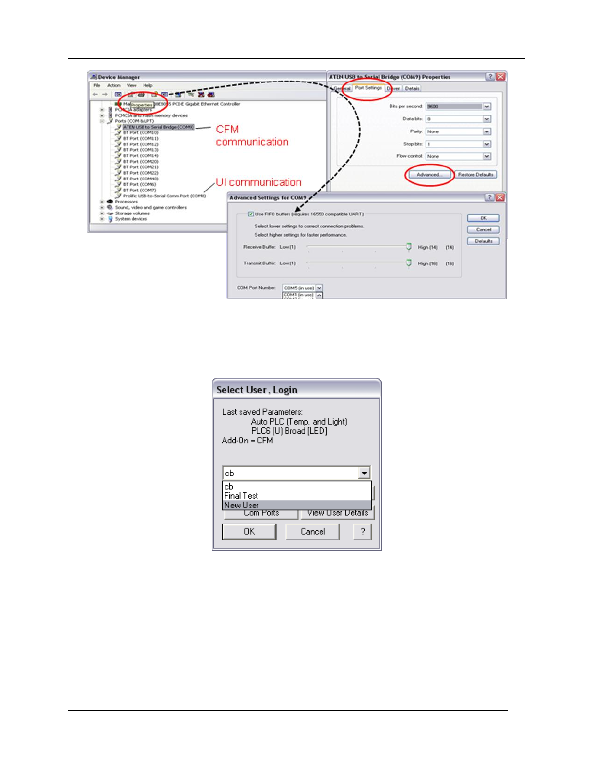
Getting Started –
You can run your RCS software by going to Start, Programs, CIRAS-2 Remote Control Software or by
clicking the CIRAS-2 Remote Control Software icon on your desktop screen. The first time that you run
RCS the Select User dialog (below) will be displayed on the screen:
Later, when you set up your preferences and settings, this information will automatically be saved for you.
The most recently used preferences and settings will load each time that the RCS program is
subsequently started, and the login procedure will be circumvented.
The „New User‟ option facilitates multiple operators sharing the same equipment without altering or
overriding each others individual settings. Each „User‟ can pre-program and permanently store several
unique sets of hardware/software settings and routines under which CIRAS-2 is operated. For example,
you can set up CIRAS-2 to measure leaf-level gas exchange responses to controlled environmental
conditions, or to measure soil respiration rates.
CIRAS-2 Operator's Manual Version 2.04
- 15 -
Page 18
Getting Started –
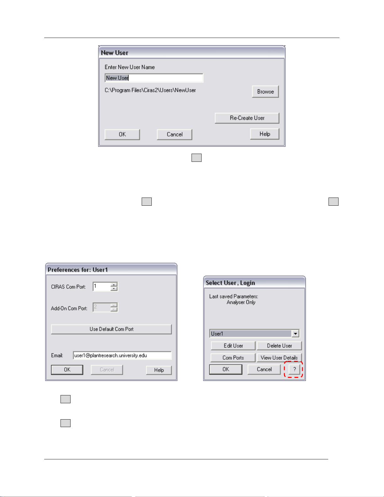
Select „New User‟ from the drop down list and click OK. Next, enter a unique name (above) that will be
used to create the folder which will hold important preferences and CIRAS-2 set up information for a
particular end user. The file will be saved in the following subdirectory on your computer:
C:\ProgramFiles\Ciras2\Users\
After entering a user name, select OK . You will be informed as to the exact location of the file. Click OK
to continue. The Preferences dialog will now open. Enter the Com port that is being used with CIRAS-2.
The correct COM port MUST be selected for inter-communication between the computer and CIRAS-2.
There are 99 COM port options currently available to the user. By default, the COM port on the UI is set to
COM1. To select the appropriate COM port see the Windows Device Manager instructions above (Step 7.
Connect CIRAS-2/PC interface cable. Finally, enter a valid email address as an additional identifier
associated with your newly created User identity and to help with technical support. Your email address
will be contained in subsequent data and diagnostic files.
Click OK to save your changes to Preferences for: (above, left). The Login dialog automatically defaults
to the basic „Analyser Only‟ setting (CIRAS-2 as a stand-alone CO2 and H2O IRGA).
Click OK. The CIRAS-2 Measurement Screen will appear in Analyser Only mode. Next, click on Setup in
the CIRAS main menu to open the Settings dialog. At this time you will only need to make two simple
selections.
CIRAS-2 Operator's Manual Version 2.04
- 16 -
Page 19
Getting Started –
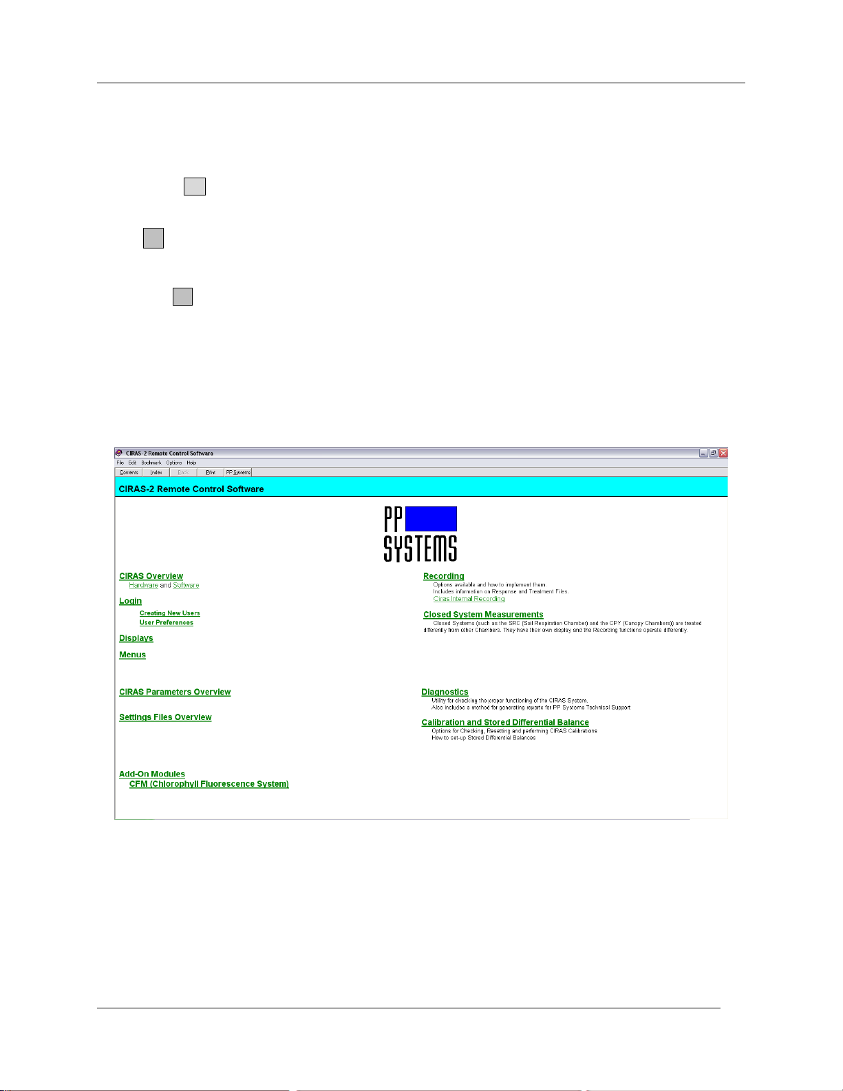
Open the „Accessory‟ drop down list containing the standard cuvettes and chambers that may be used
with CIRAS-2. From this list select „PLC6 (U) 18 mm diameter insert‟ – this is the most common leaf
cuvette used with the CIRAS-2 system. By making this selection, various other options will automatically
be set to default settings that are standardized for the PLC6 (U) cuvette. In the „Light Type‟ list select
„LED‟. If using a different insert with the PLC6(U) or a different cuvette, select the appropriate option from
the list. Click OK. The Settings dialog and all of its options will be described in detail later.
Click ? at any time for On-line help
While working with CIRAS-2 from your PC or notebook you have access to compiled Windows Help Files
through the ? buttons associated with most CIRAS-2 screens and dialog boxes. Help Files are contextsensitive, providing detailed information about the screen or user option you are currently viewing.
PP Systems is continuously updating our print and on-line documentation to reflect hardware and software
changes. Due to this some images and information contained in compiled Windows Help Files are out of
date and may not reflect exactly the current version 1.07 RCS software. Always consult the print version
of the Operator‟s Manual first before using the on-line resource. Please note: Help Files are not
available with the Windows CE version of RCS used with the UI.
CIRAS-2 Operator's Manual Version 2.04
- 17 -
Page 20

Preparations for Use –
Preparations for Use
Your system has been factory calibrated before shipment to you. Therefore, there is no need to perform a
calibration of your equipment prior to use.
At this point you should have installed the CIRAS-2 Remote Control Software (supplied on CD ROM) to
the computer(s) you will use to operate CIRAS-2. Both the Windows (for use with your notebook or
desktop PC) and Windows CE (factory-installed on the User Interface) versions of CIRAS-2 RCS are
virtually identical. We recommend familiarizing yourself thoroughly with CIRAS-2 in a controlled indoor
setting before taking the system into the field.
To install the software, please refer to the Getting Started section of the Operator‟s Manual on page 13.
System Preparation
Step 1. Insert 12V NiMH battery packs into main console
Step 2. Connect CIRAS-2 power supply
Step 3. Make Leaf Cuvette electrical and gas connections
Step 4. Connect leaf cuvette power cable to external 12V DC Power Supply
Step 5. Inspect absorber columns (desiccants, etc.) and water vapor equilibrator
Step 6. Insert CO2 cartridge
Step 7. Connect CIRAS-2/PC interface cable (optional for computer RCS control)
Step 8. Power on CIRAS-2
Step 9. Close the leaf cuvette
Step 10. Start the CIRAS-2 Remote Control Software on your PC (optional for computer RCS control)
Step 1. Insert 12V NiMH battery packs into main console
For field measurements, the 12V NiMH battery packs should be fully charged for optimal results. This is
best achieved by connecting the batteries to their respective chargers the night prior to measurements.
This ensures that the battery packs are fully charged and ready to power the console and cuvette for
several hours of field measurements, depending on temperature and LED light use. Batteries should
have arrived fully charged with your CIRAS-2 shipment.
If the batteries require charging, unscrew the threaded cover connector on the battery pack, and taking the
battery charger cable, align the battery charger connector with the three-pin battery pack connector.
Thread the cable connector clockwise to complete the connection. The battery chargers have an LED
indicator that glows red while fast-charging and green in the fully charged state. Normally, it takes
approximately 4 hours for a discharged battery to be fully charged.
The CIRAS-2 main console has two battery compartments which accept the left and right 12V NiMH
battery packs supplied with your system. Each battery pack has a thick notch (12mm) on the bottom and
thin notch (6mm) on the top, so the batteries are properly oriented with the positive/negative battery
terminals towards the bottom. Assuming the battery packs are fully charged, slide one battery into the left
battery compartment until it snaps into place. Slide the other battery into the right battery compartment.
Step 2. Connect CIRAS-2 power supply
For laboratory work the CIRAS-2 mains power supply can be used with or without CIRAS-2 battery packs.
However, please note: At least one charged 12V NiMH battery must be in place when the system
is first powered on. After CIRAS-2 is powered on, the battery may be removed if required. Running
CIRAS-2 Operator's Manual Version 2.04
- 18 -
Page 21
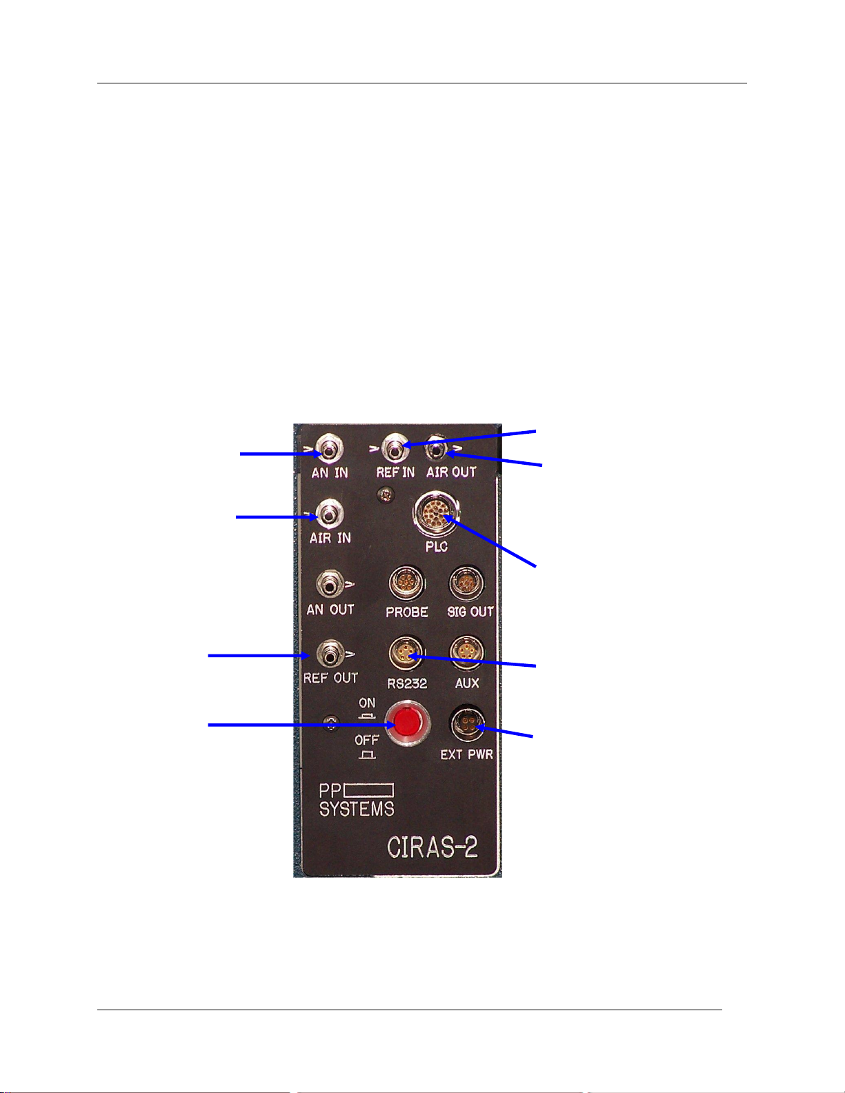
the system from mains power will prevent the battery packs from draining during this exercise. The mains
Connect the leaf
cuvette tubing labelled
“A” to the gas entry port
“AN IN”.
Air supply for analyzer
– alternatively, source
of ambient air when no
CO2 control desired.
“REF OUT” - reserved
for closed system
applications.
Power (On/Off)
Switch.
Connect one leg of the leaf
cuvette tubing labelled “R” to
the “REF IN” and the other
leg to the “AIR OUT” gas
port.
Connect the leaf cuvette
electrical plug to the “PLC”
socket. Note the orientation
of the red dot. It should be
at the top and in the middle.
Push firmly until it latches.
RS232 socket. When
operating the CIRAS-2
remotely from a computer.
Connect CIRAS-2 Power
Supply to External Power
socket.
power supply does not charge the CIRAS-2 battery packs.
Connect the mains power supply (supplied by PP Systems) from the electrical outlet in your lab to the EXT
PWR socket located on the electrical/gas connection panel. The power supply is fitted with a special 4-pin
plug that is designed to fit only into the EXT PWR socket. Proper care must be taken not to inadvertently
force the plug into any other socket, which will cause damage to CIRAS-2‟s electronics.
Step 3. Make Leaf Cuvette electrical and gas connections
Locate the leaf cuvette electrical socket labelled “PLC” on the electrical/gas connection panel. Plug the
18-pin cuvette electrical connector into this socket, ensuring that the red dot on the connector is in the 12
o‟clock position (top, middle). Push in until the connector latches.
To make the cuvette gas connections locate the 3 gas entries AN IN, REF IN, AIR OUT at the top of the
panel:
CIRAS-2 gas/electrical connection panel – detailed view
Note that it does not matter which leg of the tubing marked “R” is connected to the “REF IN” or “AIR OUT”
gas entries. Push each connector firmly onto the appropriate gas entry until you hear it lock in place.
If your system includes the integrated Chlorophyll Fluorescence Module (CFM), locate the CFM
On/Off switch (beneath the UI) and set to the Off position. You will find detailed descriptions of
simultaneous chlorophyll fluorescence/gas exchange functions in the CFM section on page 96.
Preparations for Use –
CIRAS-2 Operator's Manual Version 2.04
- 19 -
Page 22
Preparations for Use –
MS
Molecular Sieve
D
Drier (Envirogel)
SL
Soda Lime
Column
Chemical
When fresh, chemical is:
When exhausted,
chemical is:
1
1/3rd Molecular Sieve
2/3rd Envirogel
White (Non-Indicating)
Orange
White (Non-Indicating)
Green
2
Soda Lime
Green
Brown
3
Soda Lime
Green
Brown
4
1/3rd Molecular Sieve
2/3rd Envirogel
White (Non-Indicating)
Orange
White (Non-Indicating)
Green
5
Envirogel
Orange
Green
Step 4. Connect leaf cuvette power cable to external 12V DC Power Supply
(Optional) - All automatic style leaf cuvettes are supplied with a power supply cable which allows you to
power the cuvette (temperature and light control) from an external 12V battery or 12V DC regulated power
supply if required. One end of the cable has alligator-style clips (red/positive and black/negative) for
connection to a 12V battery or power supply. The other end has a white plastic socket which connects to
the white plastic plug on the leaf cuvette cable. For example, if your CIRAS-2 system includes a PLC5(C)
Conifer Cuvette with the LED light unit, then you must connect to external power due to the additional
voltage requirements of the conifer cuvette.
Step 5. Inspect absorber columns and water vapor equilibrator
Absorber columns are labelled on the bottom of the CIRAS-2 console as follows:
All chemicals should be fresh and columns firmly seated in the correct manifold ports as follows:
When any of the desiccants are approximately 2/3rd exhausted (e.g. when soda lime is 2/3rd brown), the
entire contents of the absorber column should be replaced.
Please note: Molecular sieve desiccant is non-indicating and does not change color when
exhausted. Therefore, the general rule is that you should ALWAYS change this desiccant when
the Envirogel desiccant (in the same column) is 2/3
Important Note: Until June 2003, we used a desiccant called “Drierite” instead of Envirogel. Both work
similarly, but the layout of the CIRAS-2 absorber columns is slightly different. For more information on the
layout of absorber columns based on the different drier desiccants, please visit our Users webpage and
download the application note titled “Use of Drierite And Envirogel With CIRAS-1 and CIRAS-2”.
Inspect absorber column end caps and ensure they are correctly seated and that the sealing “O” rings
have not rolled out of position. The Water Vapor Equilibrator should be inspected to ensure that it is firmly
seated in its manifold. An image and description of the absorber columns can be seen below.
rd
exhausted.
CIRAS-2 Operator's Manual Version 2.04
- 20 -
Page 23
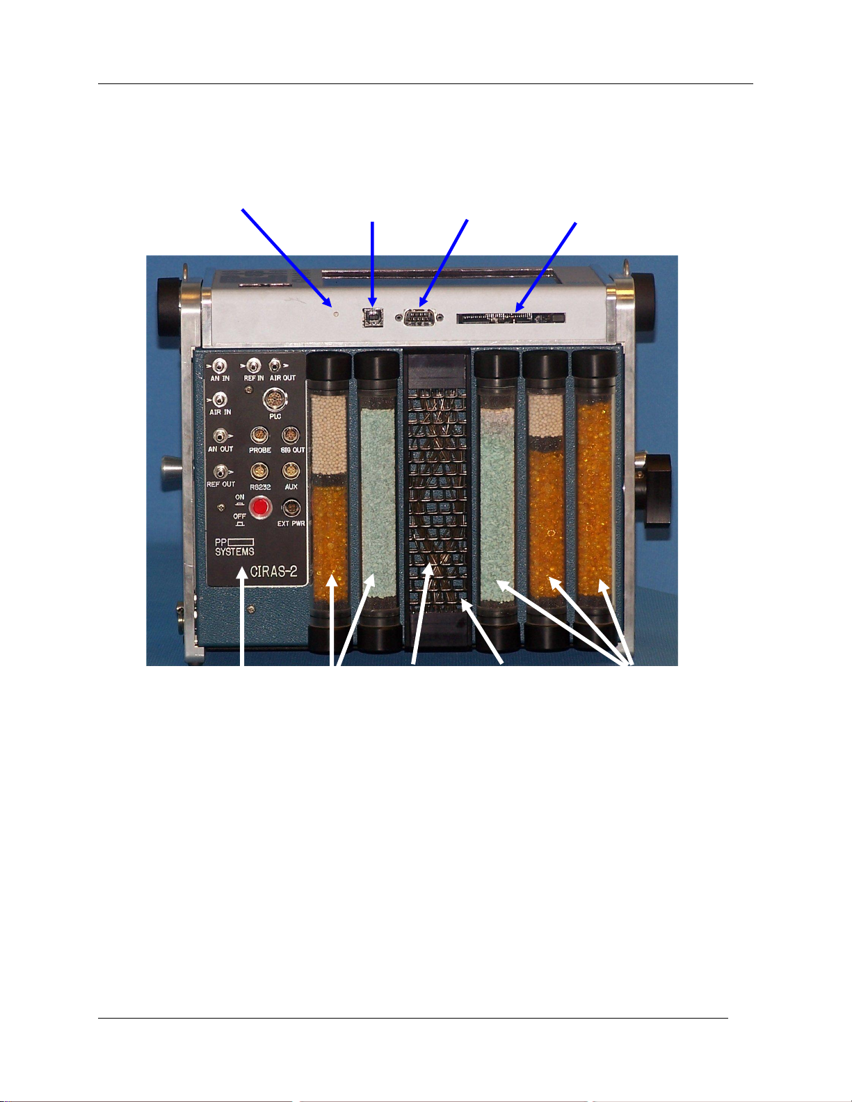
UI Reset USB RS232 PCMCIA (“flash card”)
Port Port Slot
Gas and Zero Air Water Vapor Green Transmission CO2/H2O Control
Electrical Columns Equilibrator Light Columns
Connections
Panel
CIRAS-2 Console - Front Layout
Preparations for Use –
Step 6. Insert CO2 cartridge
While still positioned inside the CIRAS console twist the CO2 cylinder holder several turns (counterclockwise). This will loosen the regulator body from the black holder. Remove the entire CO2 holderregulator assembly from the CIRAS console by pulling outward. Finish unscrewing the loosened regulator
by hand. The CO2 cylinder will remain firmly attached to the regulator body – pull it away from the
regulator. Discard the old cartridge if exhausted (see below).
Spin the narrow end of a CO2 cylinder between your fingertips to lightly lubricate it. Slide the new cylinder
into the holder with the narrow cylinder neck facing out towards the open end of the holder. Thread the
regulator body into the cylinder holder just until it makes contact with the CO2 cylinder – do not attempt to
tighten by hand. Place the entire assembly back into the CIRAS console, making sure that the regulator
body is completely seated (simultaneously push and turn slightly until the regulator drops in several
additional mm). Screw in (clockwise) until just hand tight, this will pierce the CO2 cylinder, at which point
CIRAS-2 Operator's Manual Version 2.04
- 21 -
Page 24
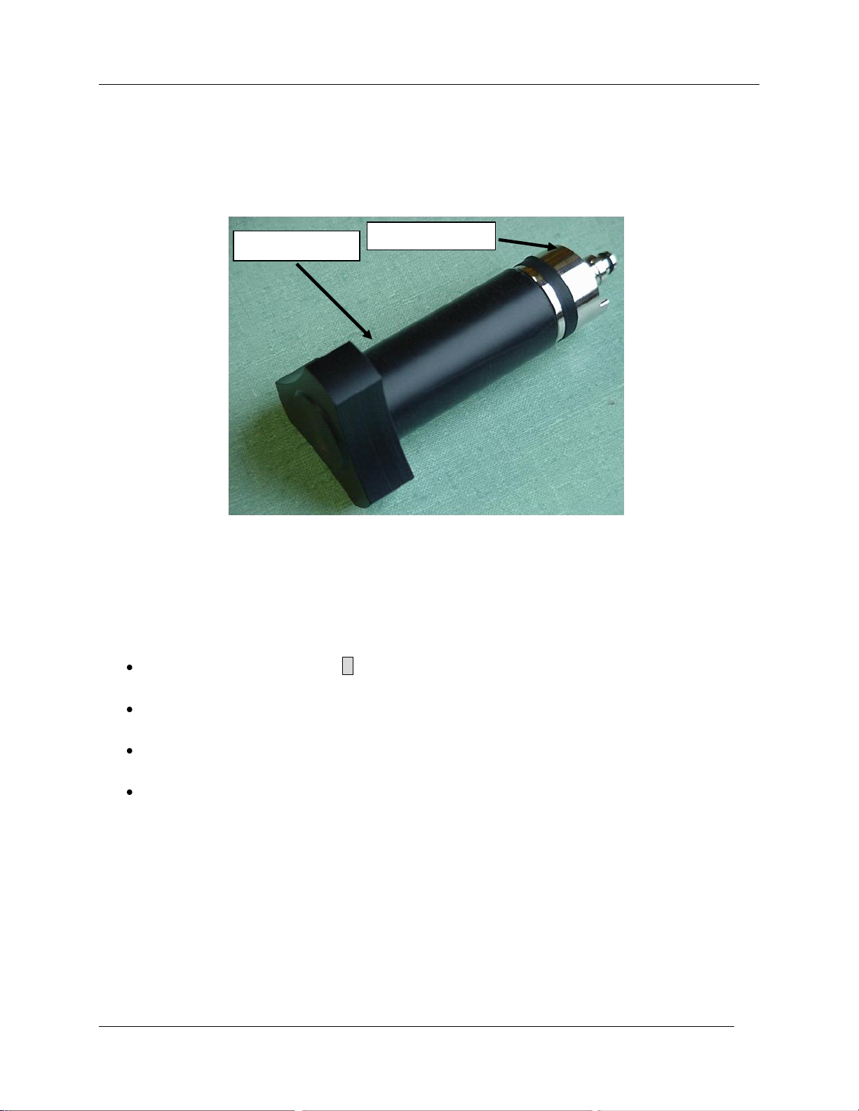
Preparations for Use –
Cylinder Holder
Regulator Body
you may hear a faint release of the pressurized gas. Back off the holder slightly (counter-clockwise), less
than one quarter turn.
CO2 Holder and Regulator Assembly
Important Note
You must allow at least 24 hours to elapse before changing the CO2 cylinder. If you are not sure that the
CO2 cylinder is sufficiently full prior to making measurements, we recommend the following:
In the main RCS screen click C to access CO2 Control Setpoints (see Data Display and Control
Values on page 26).
Set CO2 to 1500 ppm. If the CO2 concentration does not achieve 1500 ppm and steadily drops, it
is safe to change the cylinder even though there will be a slight residual pressure.
If the CO2 value achieves or comes close to 1,500 ppm and remains stable, the CO2 cylinder
should NOT be removed, as it remains pressurized.
You can begin measurements without changing the CO2 cylinder at this time. Always bring spare
CO2 cartridges and regulator o-rings with you when working in the field.
Step 7. Connect CIRAS-2/PC interface cable
Follow these instructions if you choose to operate CIRAS-2 via your computer at this time. If you will be
operating CIRAS-2 directly through the UI, as in the field, please skip to Step 8. Simultaneous operation
of CIRAS-2 from a computer and the UI is not possible. Connect the USB plug to a USB port on your
computer. Connect the opposite end of the cable with the 5-pin plug into the socket labelled “RS232” on
CIRAS-2. Align the red dot on the connector so it is at the 12 o‟clock position of the RS232 socket - click
into place.
CIRAS-2 Operator's Manual Version 2.04
- 22 -
Page 25
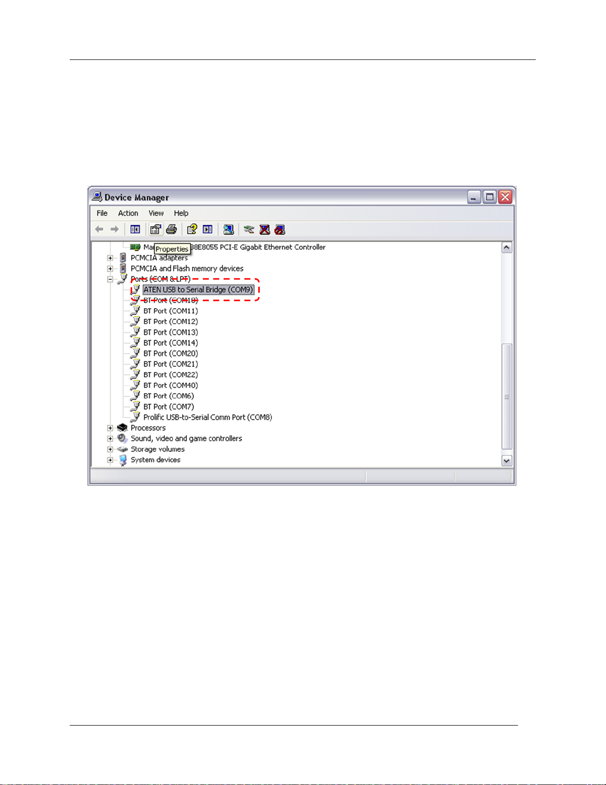
Preparations for Use –
CIRAS-2 uses default COM ports which may have been previously assigned to other devices used with
your computer. On your computer look in Windows Device Manager to determine to which Com Port your
USB device has been assigned: (description below based on Windows XP)
From the Windows Start Menu open Control Panel – click on the System icon (may be under Performance
and Maintenance) – on the System Properties box click the Hardware tab – click on Device Manager –
expand the Ports (COM & LPT) list by clicking the + button (see below). Note to which COM port your
device (USB to Serial Bridge) has been assigned for Step 10.
Step 8. Power on CIRAS-2
Switch on CIRAS-2 by pressing the red “On/Off” button on the back panel. When powered, the switch
should illuminate bright red. The cuvette fans and CIRAS-2‟s internal pumps should be running at this
point. You should also see the green LED flashing behind the water vapor equilibrator. Within 30
seconds the User Interface will become active and the UI remote control software (RCS) will load. RCS
will attempt to automatically set parameters and load default settings.
Whenever you operate CIRAS-2 through the integral UI (without RS232 connection to computer)
the RCS settings are relayed normally. If you are attempting to connect to CIRAS-2 with your
computer via the RS232 cable, you may see a Communications Error dialog box in the UI display
indicating that CIRAS-2 cannot simultaneously communicate with your PC and the integral UI.
When the Communications Error dialog appears:
CIRAS-2 Operator's Manual Version 2.04
- 23 -
Page 26
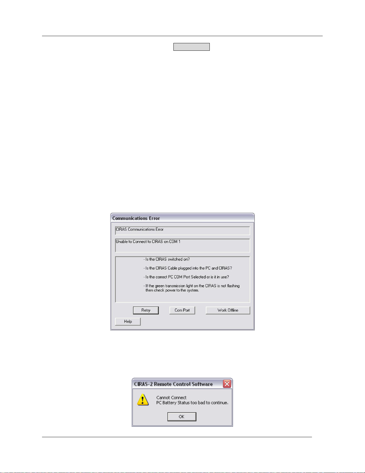
Preparations for Use –
Using the mouse pointer on the UI, click the Work Offline button, then select File - Exit from the
CIRAS menu bar on the UI. Your UI will display the blue Windows desktop with a white PP
Systems logo.
Step 9. Close the leaf cuvette
Once the RCS program loads the LED light unit will self-calibrate in a process called “tuning” (see LED
Tuning on page 25). This automatic function begins each user session when a LED light unit is attached.
Close the cuvette to ensure successful tuning of the LED light unit. If you forget to close the cuvette an
error message will appear prompting you to perform the LED tuning manually from the RCS Utilities
menu. Close the leaf cuvette by pushing down the lever on the top of the cuvette handle.
Step 10. Start CIRAS-2 RCS program on your computer
Launch the PC version of RCS from your computer‟s Start Menu or Desktop shortcut icon. Once you
have established a connection, CIRAS RCS will automatically load default settings and begin LED tuning.
Within several minutes the CIRAS-2 system will come to its normal operating temperature of 55 °C.
During this time you can begin familiarizing yourself with the Parameters Editor and optimizing the CIRAS2 system for your needs.
If you see the following Communications Error dialog as the RCS program attempts to establish
communications with CIRAS-2, check that each of the four listed conditions are satisfied. Click on the
Com Port button and select or enter the Com Port number in the CIRAS Com Port field that corresponds
to its assignment in Device Manager (see Step 7 above). There are 99 selectable COM ports.
If your laptop battery is undercharged the following CIRAS-2 RCS error dialog may appear on your
computer screen. You can avoid this by beginning the session with a fully charged battery or by switching
to AC power from a wall outlet.
CIRAS-2 Operator's Manual Version 2.04
- 24 -
Page 27
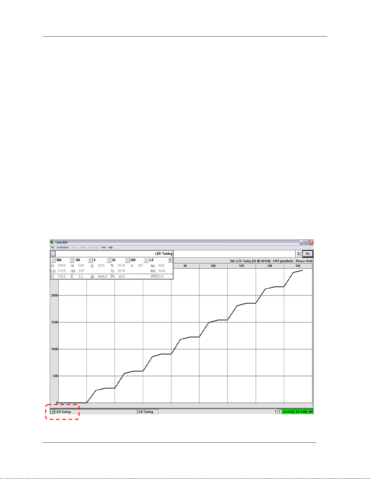
Familiarizing Yourself with the Measurement Display –
Familiarizing Yourself with the Measurement Display
CIRAS-2 is an advanced measurement system incorporating several high precision sensors for
measurement and subsequent calculation of gas exchange. The measurement display features a
Numeric Display, which contains measured data from various sensors, calculated data and Environmental
Control Settings. In addition, there is a large graphic display which can be tailored to meet your viewing
and operational requirements.
LED Tuning
If using the LED light unit, the system will go through an LED tuning procedure when first entering into the
Measurement mode. This process takes approximately 30 seconds and cannot be interrupted. During
this time, CIRAS-2 drives the light unit to a range of different levels in order to establish precise control of
light intensity, accounting for sensor changes over time and small differences between different light units
that may be used with the CIRAS-2. LED tuning may also be performed manually by selecting Utilities -
LED Tuning - Start from the menu bar. Please note:
1. Ensure that the cuvette and light unit are properly powered and connected prior to starting the
software.
2. Ensure that the light unit is correctly seated above the cuvette window and secure.
3. The cuvette must be closed during this process.
For customers that have our Chlorophyll Fluorescence Module (CFM), LED tuning will be followed by CFM
tuning.
CIRAS-2 Operator's Manual Version 2.04
- 25 -
Page 28
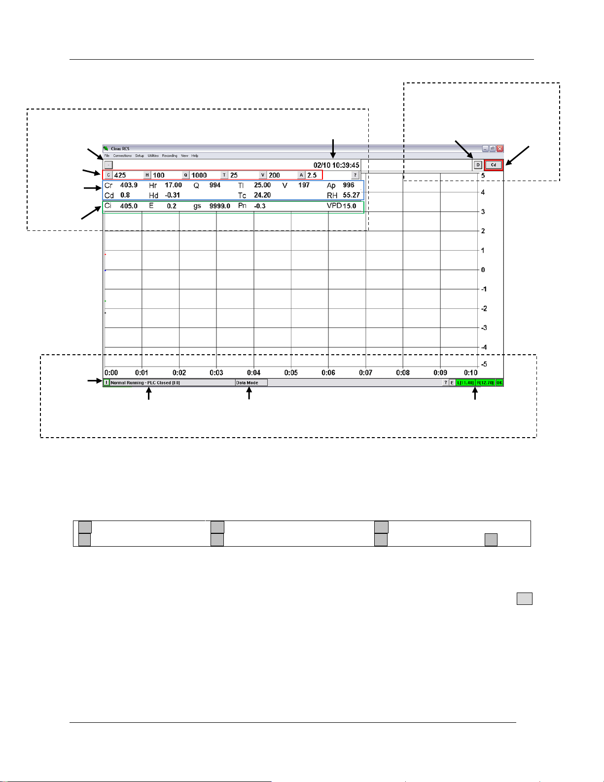
Familiarizing Yourself with the Measurement Display –
C Ref CO2 (ppm)
H Ref H2O (mb or % of ambient)
Q PAR (µmol m-2 s-1)
T Leaf Temperature (ºC)
V Chamber Flow Rate (ml min-1)
A Leaf Area (cm2)
? Help
Selected Y
Axis Variable
CIRAS Date
and Time
Graph Display Options
Plot Type Toggle
Status Bar
Errors and
Warnings
CIRAS Status
CIRAS Mode
Power Status
Data Display and Control
Measured
Parameters
Calculated
Variables
Display Toggle
Control Setpoints
Gas Exchange Measurement Screen
Data Display and Control Values
Control Setpoints
Control Setpoints can be changed dynamically in Measure Mode, but these changes are temporary and
are NOT saved in the Parameters File. During measurements or while simply observing gas exchange,
click on the button for the Setpoint(s) that you wish to change and the Ciras Control Values dialog
appears. With this dialog open, you can change one or all of the Control Setpoints as desired. Click OK
to return to Measure Mode.
Please note: Changing Settings through the Setup menu are applied globally (see Cuvette Environment
on page 50) and will require a new LED Tuning when you enter Recording Mode.
CIRAS-2 Operator's Manual Version 2.04
- 26 -
Page 29
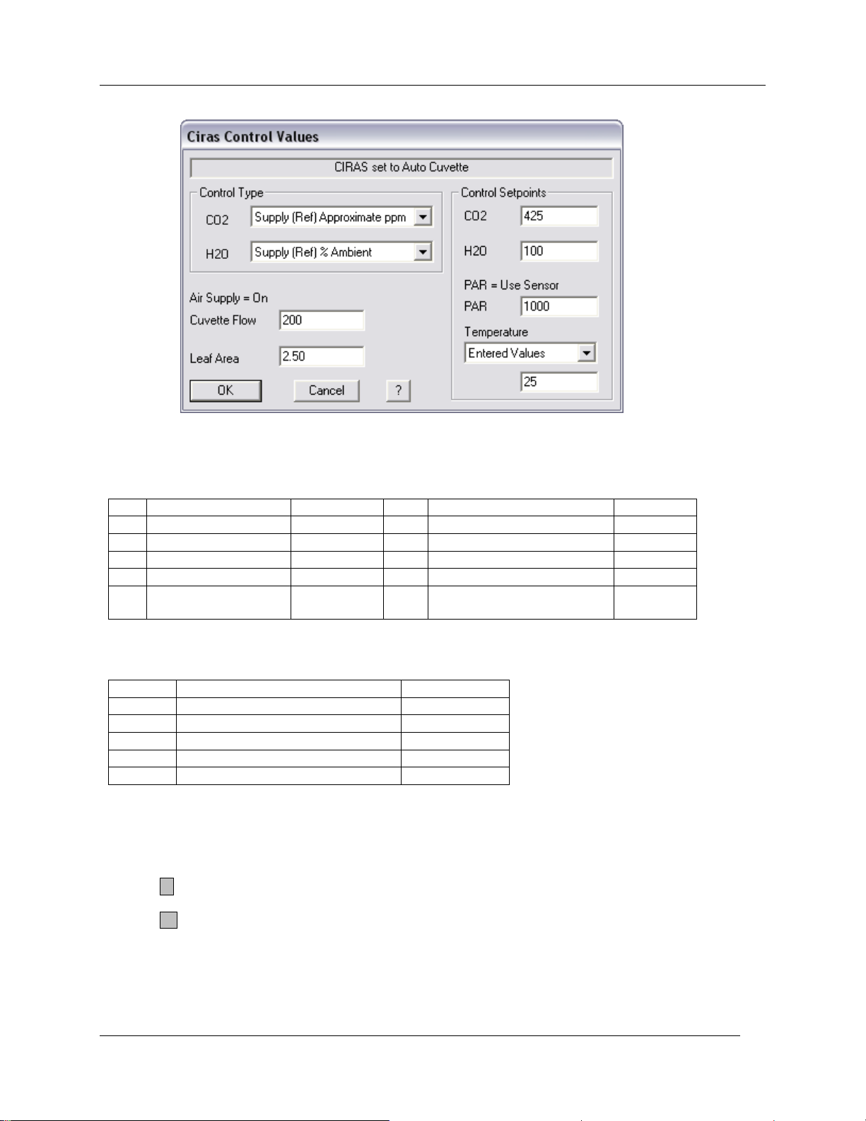
Description
Unit
Description
Unit
Cr
Reference CO2
ppm
Cd
Differential CO2
ppm
Hr
Reference H2O
mb
Hd
Differential H2O
mb
Tc
Cuvette Air Temp.
º
C
Tl
Leaf Temperature
º
C
Q
PAR
µmol m-2 s-1
V
Chamber Flow Rate
ml min-1
Ap
Atmospheric
Pressure
mb
RH
Relative Humidity
(Calculated)
%
Description
Unit
Ci
Substomatal CO2 Concentration
ppm
E
Transpiration Rate
mmol m-2 s-1
gs
Stomatal Conductance
mmol m-2 s-1
Pn
Net Photosynthetic Rate
µmol m-2 s-1
VPD
Vapor Pressure Deficit
mb
Measured Parameters
Familiarizing Yourself with the Measurement Display –
Calculated Variables
Display Toggle
Toggles Numeric Display On and Off.
Click the - button to collapse (Numeric Display off)
Click the + button to view (Numeric Display on)
CIRAS-2 Date and Time is always displayed in normal measurement, and replaced by CIRAS Mode if not.
CIRAS-2 Operator's Manual Version 2.04
- 27 -
Page 30
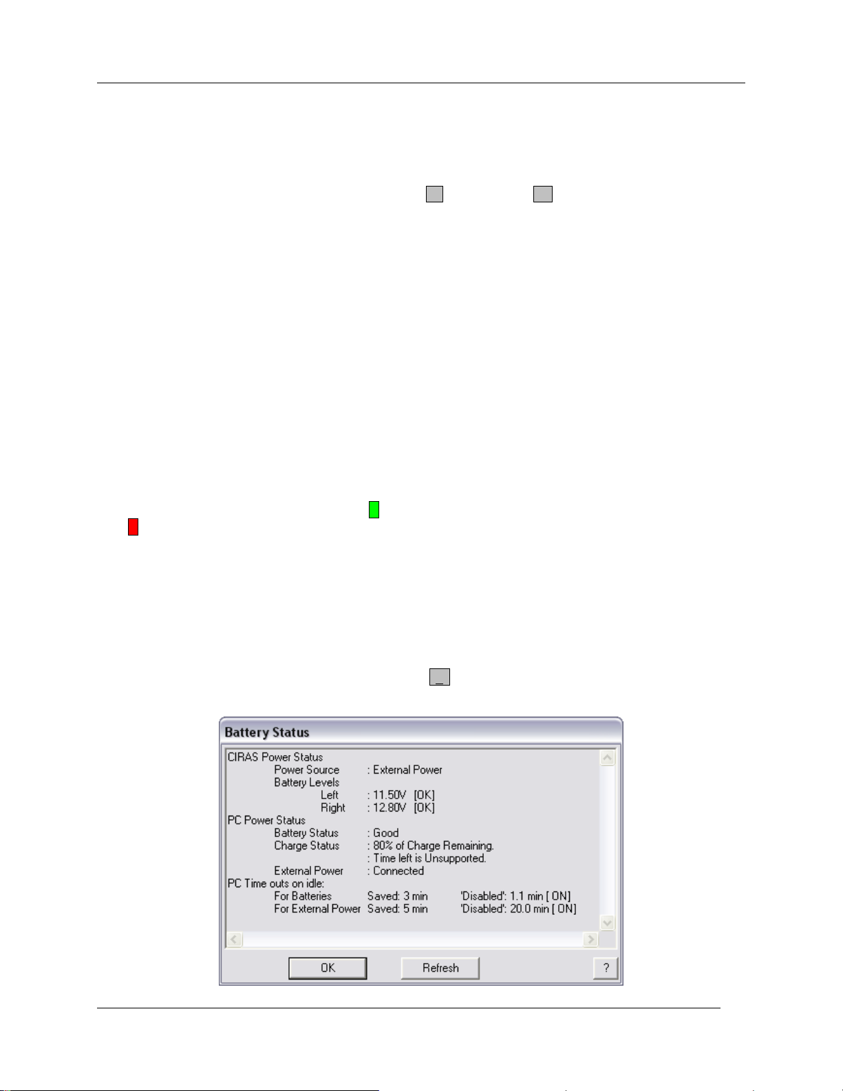
Familiarizing Yourself with the Measurement Display –
Graph Display Options
Plot Type Toggle
The graph can show either data plotted against time, or data plotted against data (maximum of two
variables). This button toggles between the Time Plot T and Data Plot D .
Current Y Axis Variable
While viewing the Time Plot the Y-Axis on the graph corresponds to the variable displayed on this button.
The border color of the button matches the plot color of the variable. Clicking on this button will toggle
through your (maximum of) four selected Time Plot variables.
See Graphing Preferences on page 57 for details.
Status Bar
Errors and Warnings
Click this button to view any recorded CIRAS-2 errors or warnings.
CIRAS-2 Status
Flashes various CIRAS-2 messages. If the E button is Green, it refers to CIRAS-2 Status Information. If
Red E, it refers to Error Information.
CIRAS-2 Mode
Refers to current functional mode of CIRAS-2 (e.g. Zero, Diff Bal, Data, etc.)
Power Status
Power Status of CIRAS-2 and PC. Clicking on the ? button displays a dialog with the status of the
CIRAS-2 batteries and PC (if connected).
CIRAS-2 Operator's Manual Version 2.04
- 28 -
Page 31
Familiarizing Yourself with the Measurement Display –
E
External Power Supply Connected
L
Left Battery in Use
R
Right Battery in Use
Color
Battery Voltage Is:
Battery is:
Green
OK
Fully Charged
Blue
>10.2 V but <11.0 V
Low, but OK
Red
<10.2 V
Very Low (Change/Charge Battery)
Grey
-----------
No Battery Installed
CIRAS-2 Power
From left to right, the first field shows the current Power Source that CIRAS-2 is using. Then follows the
Left and then Right CIRAS-2 battery status. The last field is an indicator of the Power Status of the PC.
Power Source
Left and Right Battery Power Status
Please note: The Measurement Screen is slightly different when CIRAS-2 is used for other types of
measurements than leaf gas exchange (e.g. soil respiration). Refer to Measuring Soil Respiration with
CIRAS-2 later in this manual.
CIRAS-2 Operator's Manual Version 2.04
- 29 -
Page 32
CIRAS RCS Menu Bar
CIRAS RCS Menu Bar
There are 7 Menus associated with the Menu Bar as follows:
File
Connections
Setup
Utilities
Recording
View
Help
File Menu
Recalculate Data
CIRAS-2 data recalculation is recommended with CIRAS-2 operation from the computer RCS, and not
with UI operation. This recommendation is based on the limited viewing capacity of the UI and processing
speed while using Windows CE RCS on the UI. Data recalculation is not available with CIRAS-2 Internal
Records or Closed System data (i.e. soil respiration), and cannot be performed while recording.
For further information on recalculation of data, see Recalculate Data on page 81.
Export Data
Exports all stored CIRAS-2 Data Files to your desktop PC in a user specified format for importing into
spreadsheet applications such as Microsoft Excel. Please note: export of data cannot be performed
while recording. If operating the CIRAS-2 from a PC, you will be asked to “work offline” before continuing.
For further information on exporting data, see Export Data on page 88.
View Diagnostics Report
Select and view an Extended Diagnostics Report (.dia) generated with Utilities. For further information on
performing Extended Diagnostics, see Extended Report on page 140.
Connections Menu
Login
Any user can Login under their own name at any time while the CIRAS-2 remote control program is
running. To do so, select Connections - Login. If the system is being used by another user, you will be
prompted with the following dialog:
CIRAS-2 Operator's Manual Version 2.04
- 30 -
Page 33
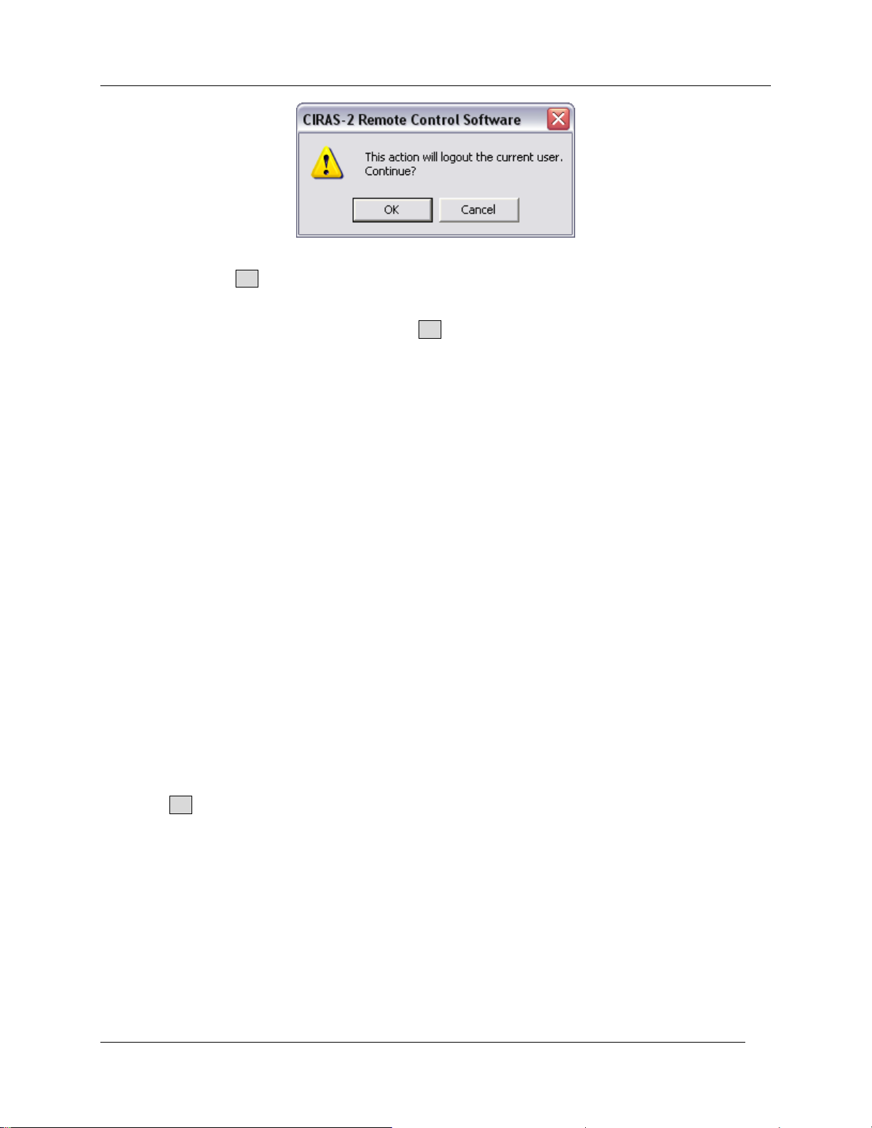
CIRAS RCS Menu Bar
As instructed, select OK to logout the current user and to enable you to “Login”. The Select User dialog
will appear allowing you to log in as described earlier in this manual (as above, pages 20-21).
After selecting the appropriate Login name, select OK to continue.
Connect
While running CIRAS-2 remote control software and connected to CIRAS-2, this function will be
unavailable (grayed out). If the user is off-line and wants to connect to CIRAS-2, click on Connect.
Disconnect
While running CIRAS-2 remote control software, but working off-line, this function will be unavailable
(grayed out). If the user is connected to the CIRAS-2 and wants to terminate the connection, click on
Disconnect.
Connect Add-On
While running CIRAS-2 remote control software, but working off-line, this function will be unavailable
(grayed out). To connect to the Chlorophyll Fluorescence Module (CFM), click Connect Add-On –
[CFM]. For further information about operating the CFM, see Measuring Chlorophyll Fluorescence with
the CFM on page 96.
Com Port
The proper COM port on your PC must be set correctly in order to work with CIRAS-2. There are 99 COM
ports available to the user as described earlier in this manual (above, page 15, 19).
To change the Com port (if required), select Connections - Com Port to highlight the appropriate setting
and click OK in the Preferences dialog. You can also enter your email address and include this
information as part of your preferences. This information is helpful to PP Systems for technical support
purposes.
Setup Menu
Settings
Calls up the Settings Editor. Allows modification of Recording Options (Response Curves, Treatments),
Parameters, CIRAS Accessories, and Custom Chambers and Cuvettes.
Refer to System Setup and Operation on page 41 for details.
CIRAS-2 Operator's Manual Version 2.04
- 31 -
Page 34
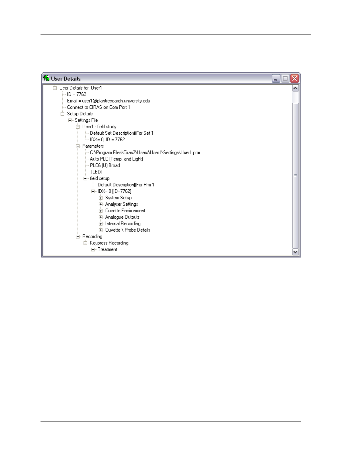
CIRAS RCS Menu Bar
View Setup Details
Provides an overview of the current Settings in a User Details dialog, including location of settings and
data files, response files, user ID, email address, etc.
Graphing
Preferences
Includes all options to set up the visual environment of the Measurement Display. Selectable features
include Plot Type, plotted variables and parameters, font size, display scales of variables, time scale.
Refer to Graphing Preferences on page 57 for details.
Reset
Clears the current Time and Data Plots and resets all selected variables to time zero.
Utilities Menu
Zero
Initiate a manual ZERO at any time by selecting this option. The Status Bar displays a ZERO message
(lower left hand corner of the display) that begins counting upwards. In ZERO mode, the initial air sample
entering CIRAS-2 is drawn through the soda lime (Absorber Column 2) to remove CO2 and then through
CIRAS-2 Operator's Manual Version 2.04
- 32 -
Page 35
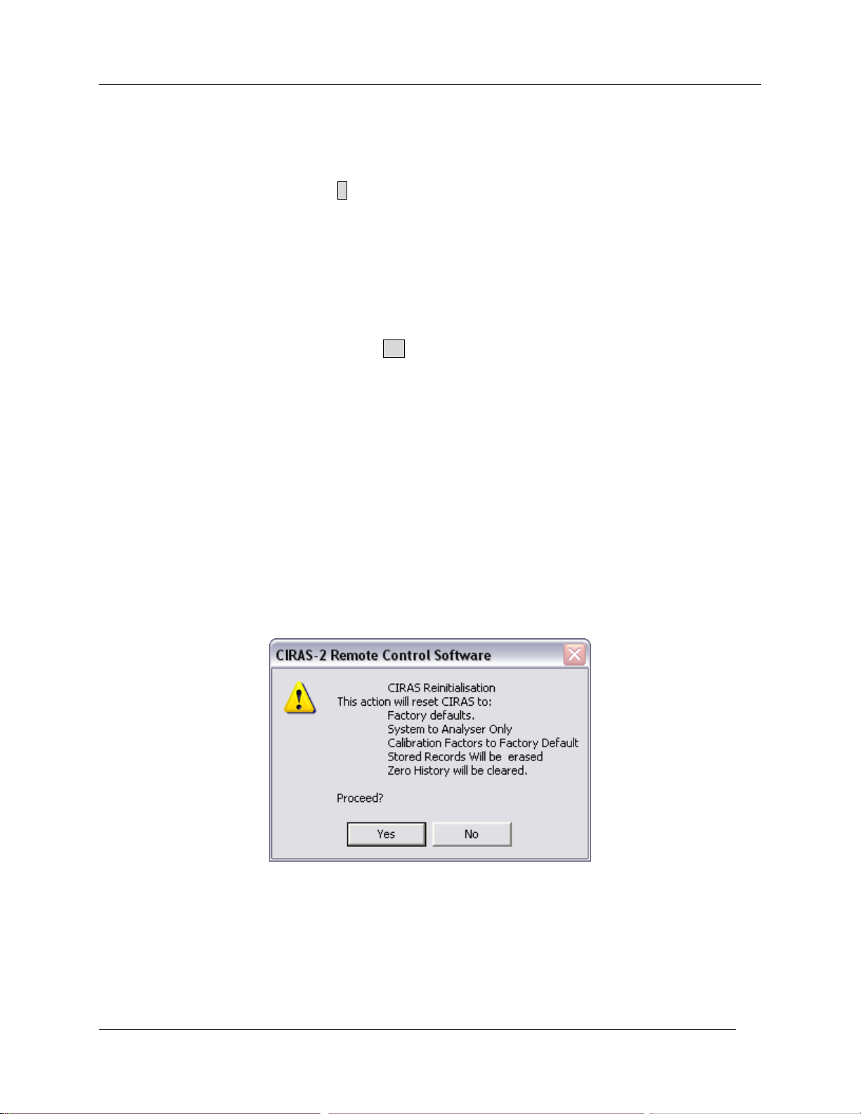
CIRAS RCS Menu Bar
the Envirogel/Molecular Sieve Column (Absorber Column 1) to remove H2O and any final traces of both
CO2 and H2O.
During this cycle, the weight of the lines being plotted on the display becomes thicker to differentiate
between normal running and ZERO cycle. Dynamic changes in control variables are suspended for the
duration of this event. A letter code Z representing the event appears on the currently plotted variable.
When completed, the Status Bar returns to its previous state (i.e. Normal Running - PLC Closed [10]).
Diff Bal
Initiate a manual DIFF BAL at any time by selecting this option. The Status Bar displays a DIFF BAL
message (lower left hand corner of the display) that begins counting upwards. In DIFF BAL mode, the
sample air is split and passed through both the reference and analysis sample cells. During the DIFF BAL
cycle, the weight of the lines being plotted on the display becomes thicker to differentiate between normal
running and DIFF BAL cycle. A letter code DB representing the event appears on the currently plotted
variable. When completed, the Status Bar returns to its previous state (i.e. Normal Running - PLC Closed
[10]).
Measure [Quit]
It terminates a Zero or Diff Bal and returns operation to measure mode. If CIRAS-2 is in the middle of
performing a Zero or Diff Bal during a measurement, it can be terminated by selecting Measure [Quit].
Initialise
From time to time, a problem may occur that will affect the calibration of the CIRAS-2. Typically, this is
due to an incorrect calibration. In the event that this happens, the system can be reset back to the original
factory default calibration. The calibration factors for each CIRAS-2 analyzer are determined at the factory
and written to an EPROM chip inside the instrument. These factors can be restored with the Initialise
function, returning the system to its original factory calibration.
Please note: If the system is initialised, CIRAS-2 will default to “Analyser Only”. Therefore, you will have
to enter Setup - Settings to re-apply your chosen operational and measurement settings.
CIRAS-2 Operator's Manual Version 2.04
- 33 -
Page 36
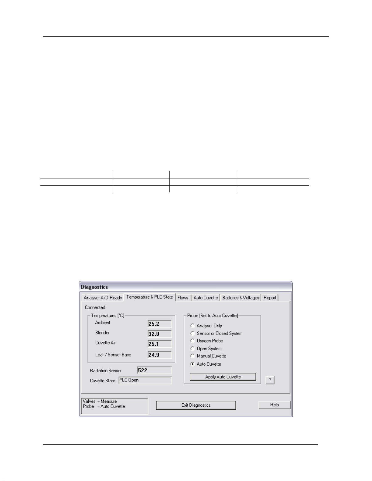
CIRAS RCS Menu Bar
Window Type
in Sunlight
with LED
with Quartz Halogen
CALFLEX IR FILTER
0.17
0.14
0.16
PLAIN GLASS
0.24
0.14
0.19
Pulse Alarm
The CIRAS-2 can be used together with external devices such as the Hansatech FMS2 Field
Fluorescence Monitoring System for simultaneous measurement of gas exchange and chlorophyll
fluorescence. To send a pulse to the FMS2, click on Utilities - Pulse Alarm. The Pulse Alarm function
sends a signal (via the Alarm line on the Probe Socket) to the external device (i.e. FMS2) to trigger a
measurement.
Simultaneous Measurements With CIRAS-2 and FMS2
The Hansatech fiber optic probe (Hansatech Part No. FMS/LFO) fits into the light unit, which has to be
modified by PP Systems (PP Systems Part No. CRS015). The standard CIRAS-2 leaf cuvette window is
an interference filter that transmits only visible light. When simultaneous gas exchange and fluorescence
measurements are performed, this must be replaced with a plain glass window that transmits infrared
radiation resulting in an increased heat load on the leaf. The PAR Energy Factor under System Setup in
the Settings dialog must be changed as shown below:
The connector to the FMS2 plugs into the Probe socket of CIRAS-2. A pulse on the alarm line (about 140
ms) triggers the FMS2 to record a fluorescence trace. The pulse is triggered when the cuvette record
button is pressed, and CIRAS-2 is set to record data direct into its memory or when the PC requests that
the pulse is sent.
Diagnostics
Initiates CIRAS-2 Diagnostics. This option is only available if CIRAS-2 and the Software are in Data Mode
(i.e. not Recording, Calibrating etc). Refer to Diagnostics on page 133 for details.
CIRAS-2 Operator's Manual Version 2.04
- 34 -
Page 37
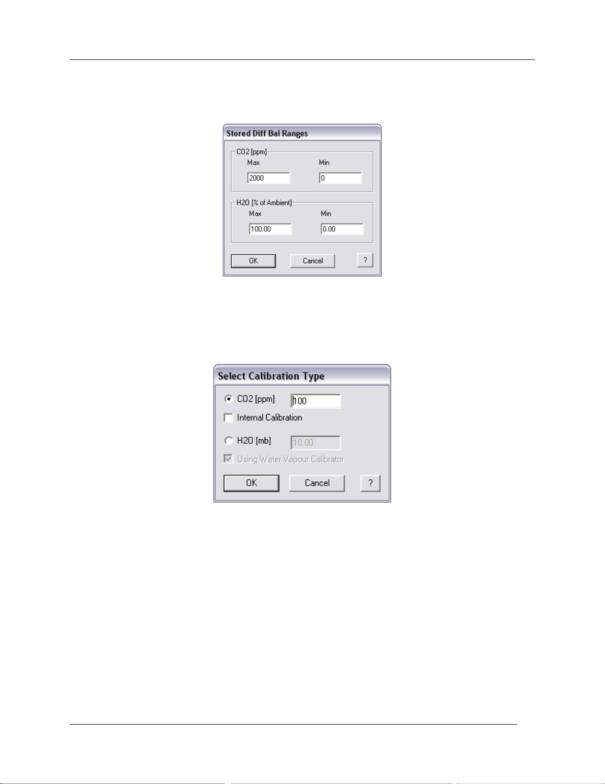
CIRAS RCS Menu Bar
Stored Diff Bal
This function allows the user to preset and store differential balance values which can be extremely helpful
when performing response curves measurements. Refer to Stored Diff Bal on page 78.
Calibration
Used to perform a full CO2 or H2O calibration on CIRAS-2. Refer to Calibration on page 143 for more
details.
Calibration Check
Used to verify the current CIRAS-2 CO2 and H2O calibration settings. Refer to Calibration Check on page
145 for details.
Calibration Reset
Resets the CIRAS-2 calibration to the Factory Default. Refer to Calibration Reset on page 147 for details.
CO2 Midpoint
Refer to CO2 Midpoint on page 147 for further details.
Please note that CIRAS-2 Firmware (EPROM) Version 1.67 or greater is required for this function.
If unsure of firmware version, see View – Quick Info in the CIRAS menu bar.
CIRAS-2 Operator's Manual Version 2.04
- 35 -
Page 38
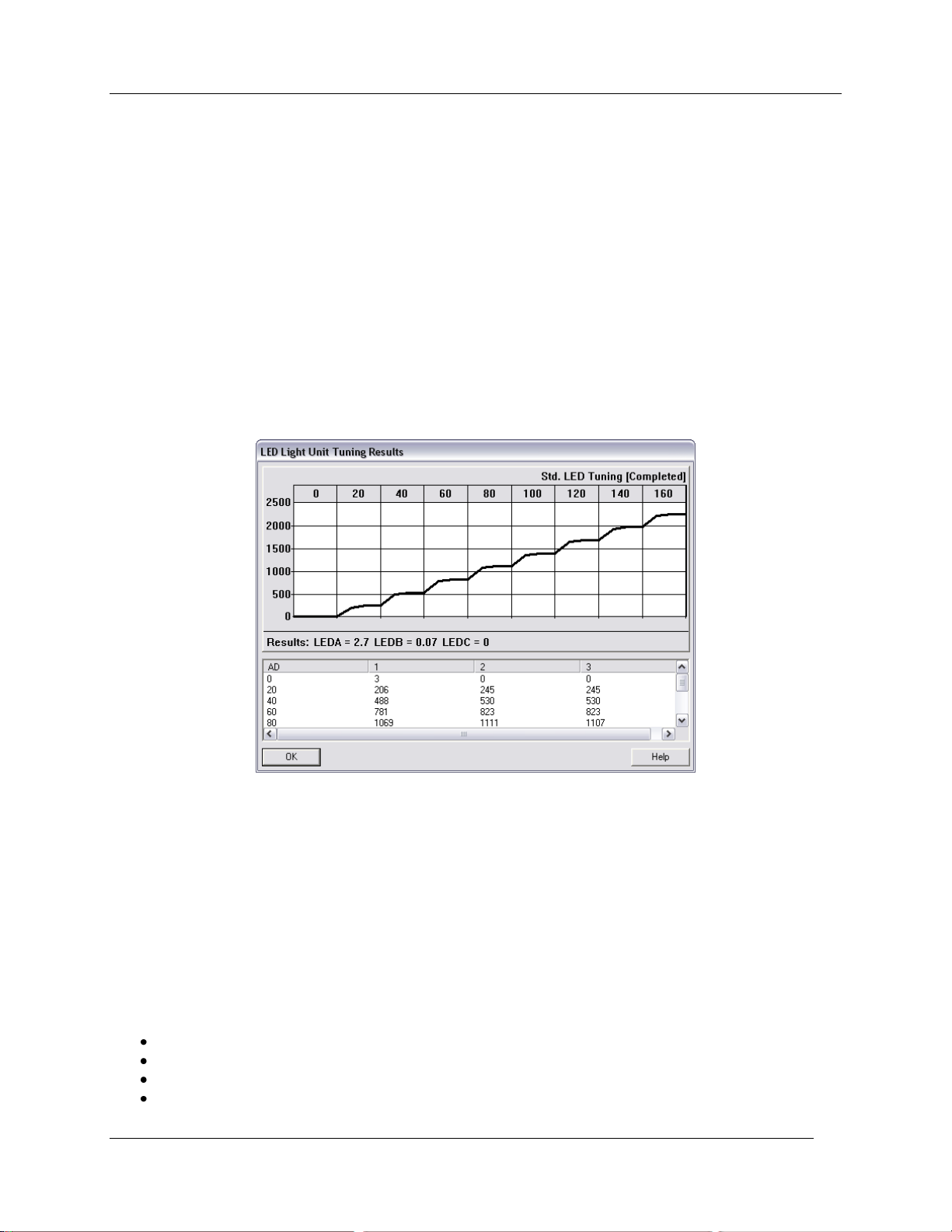
CIRAS RCS Menu Bar
Max C Determination
Allows Calculation/Resetting and checking of maximum CO2 value.
Please note that CIRAS-2 Firmware (EPROM) Version 1.67 or greater is required for this
functionality. If unsure of firmware version, see View – Quick Info in the CIRAS menu bar.
It is important that CIRAS-2 has been turned on for 20 minutes and that the CO2 cartridge is full and the
chemicals fresh. Additionally, a special T-Piece must be fitted to CIRAS-2 prior to starting the CO2
Midpoint setting. Refer to Max C Determination on page 149 for further details.
LED Tuning
Allows manual LED tuning (automatic LED Tuning performed during start up) and recalls Tuning results.
See LED Tuning on page 25 for details.
CIRAS Recording
Enable/Disable CIRAS-2 Internal Recording. Save up to 820 internal records to CIRAS-2 and initiate a
stored data dump from this menu. Please note that this is different than the normal CIRAS-2 recording
mode. See CIRAS Internal Recording on page 77 for additional details.
Recording Menu
To begin measurements select Recording - Begin. There are four recording methods available with
CIRAS-2:
Key Press
Timed
Response Curve
Batch Response Curve
CIRAS-2 Operator's Manual Version 2.04
- 36 -
Page 39
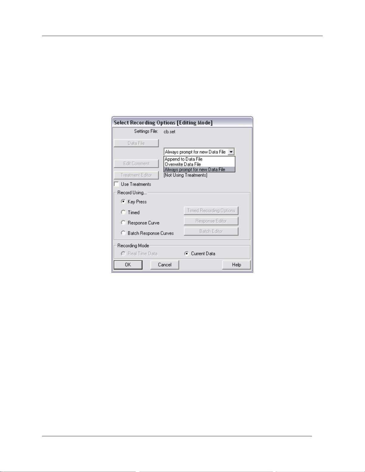
CIRAS RCS Menu Bar
All four recording methods will be described in detail in the section Observing and Recording Leaf Gas
Exchange on page 59. Please note that for Closed Systems, Recording operates differently. See for
example Measuring Soil Respiration with CIRAS-2 on page 127 for more details.
Begin
Opens the Select Recording Options dialog to name a new file or select an existing file, edit treatment
descriptions and select type of recording.
End
Select to terminate the recording session.
Start (Steady)
Allows the user to decide when to begin recording once the leaf has stabilized inside the leaf chamber.
Pause
Used to temporarily suspend recording, for example, to allow the leaf additional time to stabilize.
Single Record
Initiates a single measurement, similar to a Keypress.
CIRAS-2 Operator's Manual Version 2.04
- 37 -
Page 40
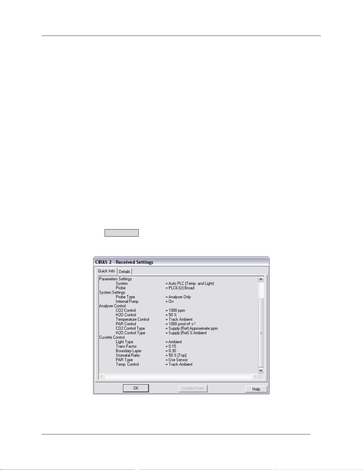
CIRAS RCS Menu Bar
Multiple Record
Used in Timed Recording to initiate multiple measurements (with Recording Blocks Enabled).
Comment/Treatment
During measurements, used to enter descriptive information relating to the measurement.
Response Level
During a Response Curve measurement, used to view the response levels (Response Selection dialog).
Plugin Record
Not currently assigned.
View Menu
Quick Info
Opens the CIRAS-2 – Received Setting dialog. Provides information such as the serial number of the
instrument, eprom version, and technical information regarding the current configuration of the CIRAS-2
system. It can be viewed at any time by selecting View - Quick Info. To view additional details such as
number of free records, Zero mode, Averaging Limit, Probe and Calibration constants, etc., click on the
„Details‟ tab. Click the Update Data button to see the most recent information/data associated with your
CIRAS-2.
CIRAS-2 Operator's Manual Version 2.04
- 38 -
Page 41
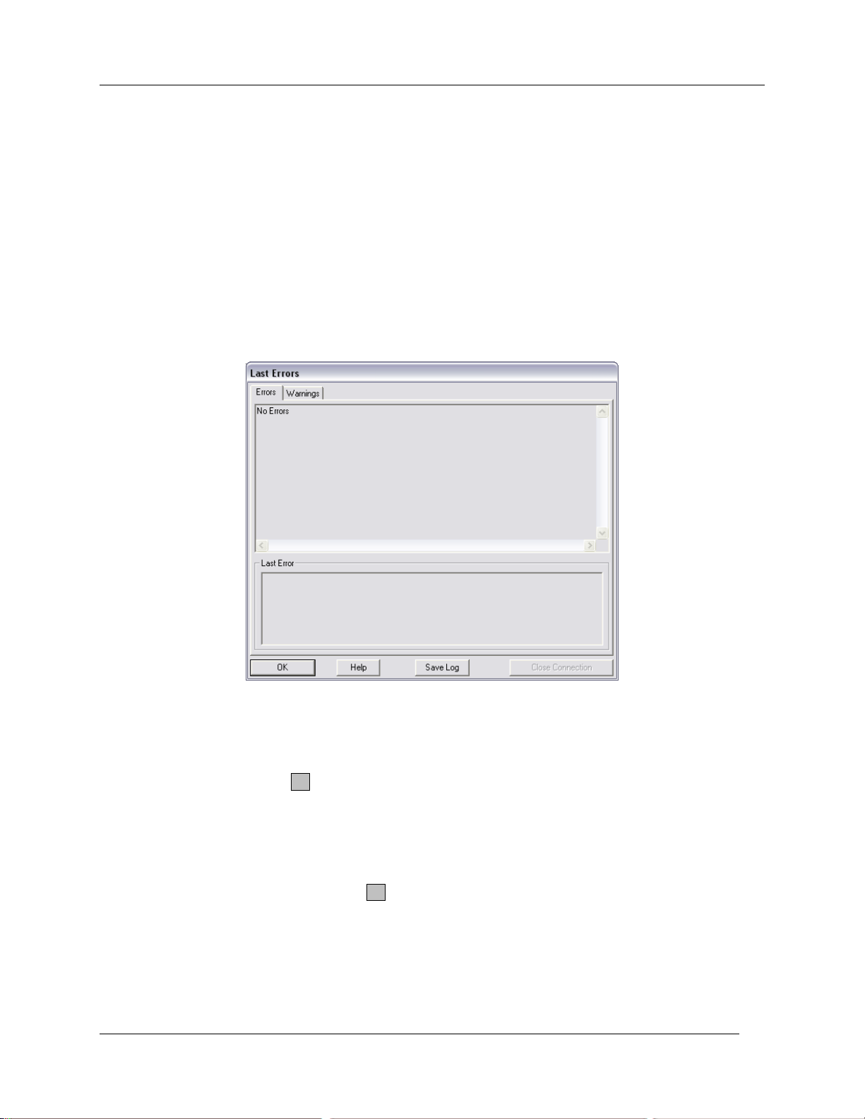
CIRAS RCS Menu Bar
Update Parameters
Causes CIRAS-2 to re-transmit its current Settings. Verifies that CIRAS-2 is using the correct settings.
Errors
Any Errors detected by CIRAS-2 can be viewed from this menu. Some errors are immediately brought to
the attention of the user, some of which may require immediate attention. For questions regarding error
messages, consult the Technical Manual or contact PP Systems. See Contact Information on page 11.
Warnings
Any Warnings detected by CIRAS-2, such as changing A/D Zero values, can be viewed from this menu.
Time Plot
To view measurements as color-coded plots over time, select View - Time Plot. Alternatively, if Data Plot
is currently selected, click the T button in the upper right hand corner of the Measurement Display. See
Graphing Preferences on page 57.
Data Plot
To view measurements as data points in a scatter plot, select View - Data Plot. Alternatively, if Time Plot
is currently selected (see above), click the D button in the upper right hand corner of the display.
Battery Status
Displays the Battery Status of each 12V NiMH battery used with CIRAS-2, and (if present) the PC‟s battery
status. See Power Status on page 28 for details.
CIRAS-2 Operator's Manual Version 2.04
- 39 -
Page 42
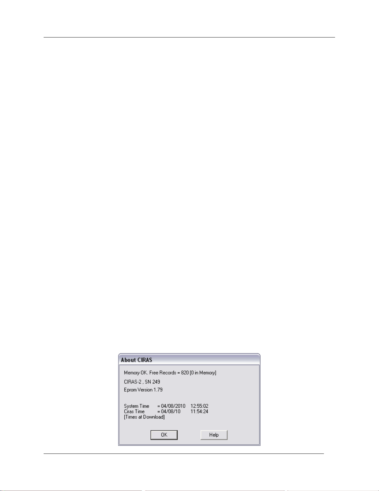
CIRAS RCS Menu Bar
Help Menu
Help
Displays the main CIRAS-2 Remote Control Software Help Menu. (Currently unavailable for the Windows
CE version of the software on the UI). This supplements information contained in the Operator‟s and
Technical Manuals. Due to ongoing updates we suggest that if you have any questions about CIRAS-2
operation, menus, etc., you first refer to the print version before searching the on-line Help menus.
About
Select Help - About to see which version of the CIRAS-2 Remote Control Software you are running.
Diagnostics
Contains information related to the 6 CIRAS-2 Diagnostics topics.
Calibration & Stored Diff Bal
Contains topics related to CIRAS-2 calibration and stored differential balance.
Recording
Contains topics related to CIRAS-2 Recording (i.e. Key Press, Timed and Response Curve recording).
Closed Systems
Describes the use of PP Systems Soil Respiration and Whole Canopy Assimilation closed system
chambers.
Add-On Modules
Opens Help Files related to the Chlorophyll Fluorescence Module (CFM).
About CIRAS
Displays the Eprom version being used in your CIRAS-2, along with the serial number of your instrument.
CIRAS-2 Operator's Manual Version 2.04
- 40 -
Page 43
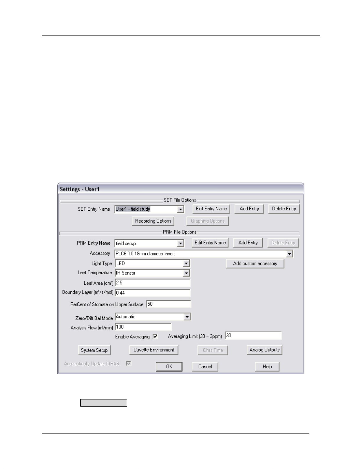
System Setup and Operation
System Setup and Operation
Settings information provides the basis for your individualized use of CIRAS-2 and will be automatically
saved for you. Selections made in the Settings dialog are global and apply universally to a CIRAS-2
session, unlike those made with the Control Setpoint buttons, which are temporarily applied to the
session. The most recently used preferences and settings will load each time that the RCS program is
started, and the login procedure will be circumvented.
Set File Options
Set Entry Name
Click on Setup in the CIRAS main menu bar to open the Settings dialog. In the „SET Entry Name‟ field at
the top of the dialog select „Default SET Name 1‟ from the dropdown list. A single Set File will allow up to
10 parameter setups (PRM Files, below) containing unique combinations of cuvette/chamber type, light
source, controlled environmental conditions, recording options and real-time graphing options.
Edit Entry Name
Next, click on Edit Entry Name, enter a short descriptive name in the Rename dialog, .e.g. your current
experiment.
CIRAS-2 Operator's Manual Version 2.04
- 41 -
Page 44
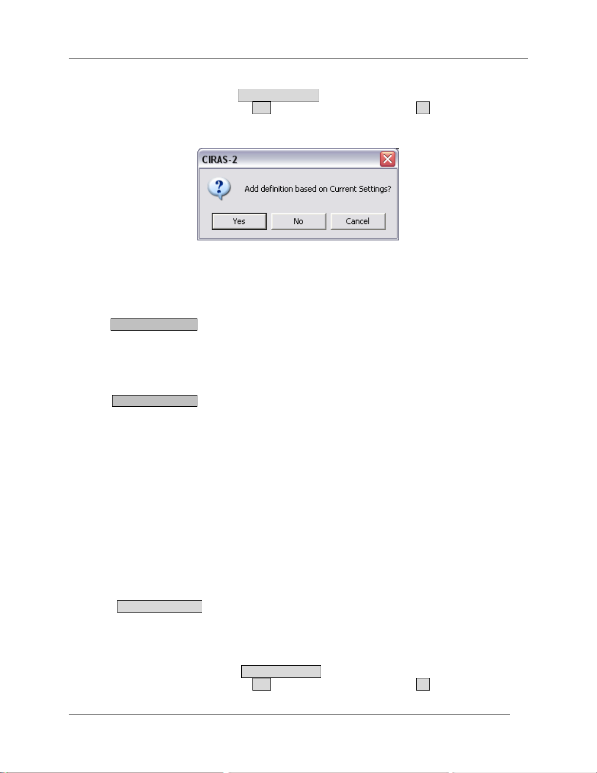
System Setup and Operation
Add Entry
To create additional Set Files click Add Entry Name and choose „Default SET Name 2‟ from the
dropdown list. In the resulting dialog click Yes to use the current parameters or No to create a unique set
of parameters. Edit the new entry as above.
Delete Entry
This removes the currently selected Set File and its parameter, graph and recording options.
Recording Options
Click the Recording Options button to set up the type of recording you wish to make. The same dialog is
also available by selecting Recording – Begin. For a detailed description see Select Recording Options
on page 60.
Graphing Options
Click the Graphing Options button to change various options associated with graphical presentation of
data in the Graph Preferences dialog. The same dialog is available by selecting Setup – Graphing –
Preferences from the CIRAS menu bar. For a detailed description see Graphing Preferences on page
57.
PRM File Options
In the „PRM Entry Name‟ field select „Default PRM Name 1‟ from the dropdown list. Up to 10 parameters
settings per Set File are allowed.
PRM Entry Name
Select „Default PRM Name 1‟ from the dropdown list.
Edit Entry Name
Click on Edit Entry Name. Enter a short descriptive name in the Rename dialog, .e.g. the
cuvette/chamber used in your measurements.
Add Entry
To create additional PRM Files click Add Entry Name and choose „Default PRM Name 2‟ from the
dropdown list. In the resulting dialog click Yes to use the current parameters or No to create a unique set
of parameters. Edit the new entry as above.
CIRAS-2 Operator's Manual Version 2.04
- 42 -
Page 45
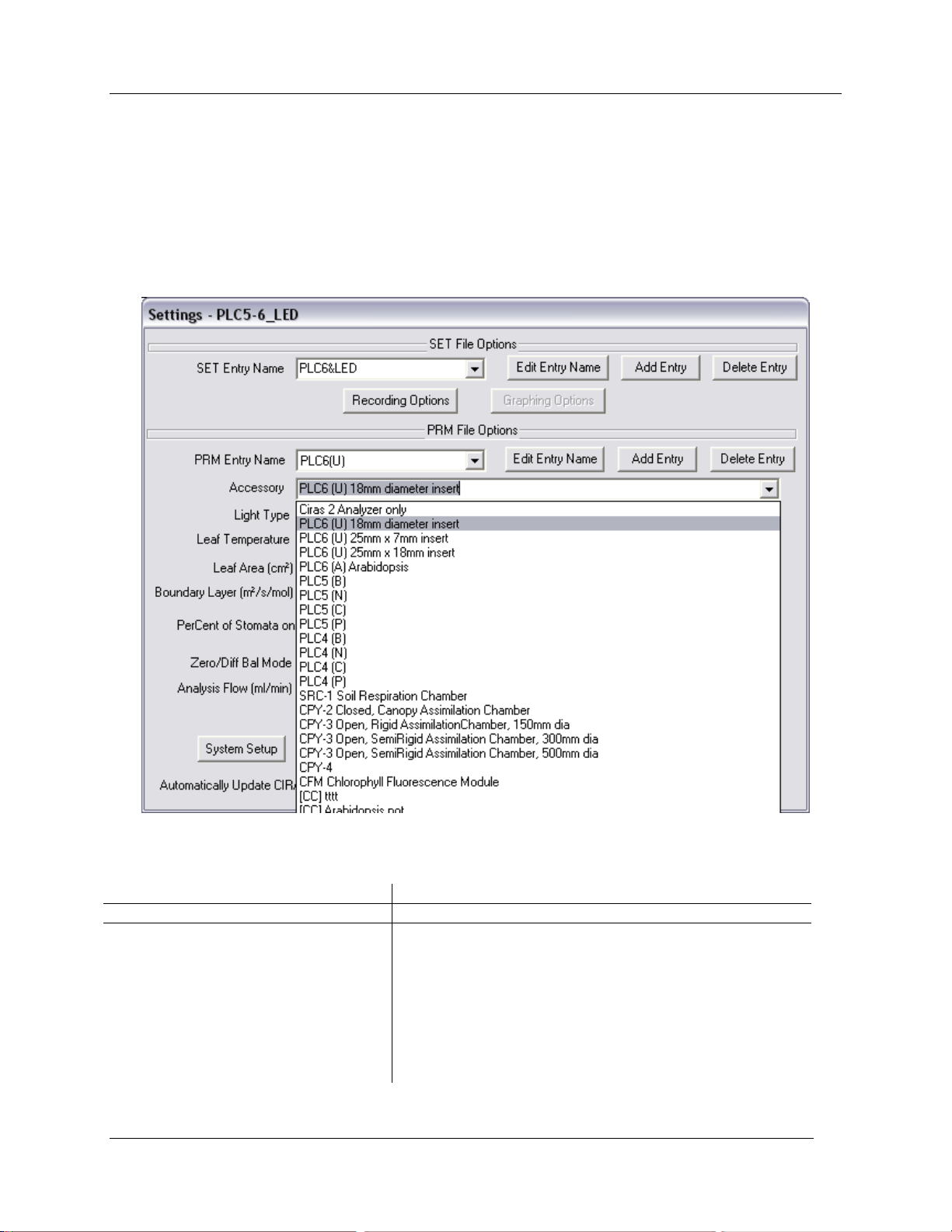
System Setup and Operation
Accessory
Cuvette/Chamber Type
CIRAS 2 Analyser Only
CIRAS-2 as stand-alone analyzer (no cuvette)
Auto PLC (Temp. and Light)
PLC6 (U) 18 mm circular (2.5 cm2 head plate)
PLC6 (U) 25 x 7 mm narrow (1.75 cm2 head plate)
PLC6 (U) 25 x 18 mm wide (4.5 cm2 head plate)
PLC6 (A) for Arabidopsis (1.29 cm2 head plate)
PLC5 (B) broadleaf (2.5 cm2 head plate)
PLC5 (N) narrow leaf (10 cm2 head plate)
PLC5 (C) conifer (10 cm2 head plate)
PLC5 (P) pod (10 cm2 head plate)
Other
Delete Entry
This removes the currently selected PRM File and its individual settings.
Accessory
Open the „Accessory‟ drop down list containing the standard cuvettes and chambers that may be used
with CIRAS-2. From this list select, for example, the standard automatic leaf cuvette „PLC6 (U) 18 mm
diameter insert‟. By making this selection, various other options will automatically be set to defaults for
this Accessory.
The table below lists several current and older-style cuvettes and chambers supported by CIRAS-2.
CIRAS-2 Operator's Manual Version 2.04
- 43 -
Page 46
System Setup and Operation
Manual PLC
PLC4 (B) broadleaf (2.5 cm2 head plate)
PLC4 (N) narrow leaf (10 cm2 head plate)
PLC4 (C) conifer (10 cm2 head plate)
PLC4 (P) pod (10 cm2 head plate)
Closed System Chamber
SRC-1
CPY-2
CPY-4 (146 mm diameter)
Other
Open System Chamber
CPY-3 5 litre Canopy Assimilation (150 mm diameter)
CPY-3 20 litre Canopy Assimilation (300 mm diameter)
CPY-3 100 litre Canopy Assimilation (500 mm diameter)
CFX-1 (for soil respiration)
CFX-2 (for soil respiration)
Chlorophyll Fluorescence Module
CFM (combined with PLC6 (U) LED light unit)
Custom Chamber
[CC] (based on open or closed system chambers)
Oxygen Probe
Not Applicable
Some Accessories are no longer available. Environmental sensors attached to Probe input such as the
PAR sensor and Soil Temperature Probe are detected automatically and do not require selection as
Accessories. If you have any questions as to which cuvette or probe type you have, refer to the original
paperwork (i.e. invoice from PP Systems), the Appendix at the back of this manual or contact PP
Systems.
Add Custom Accessory
Primarily for use with your custom-built or existing chamber. In the Settings dialog, select the PP Systems
Accessory that most closely matches your chamber. Click Add custom accessory to call up the
Custom Chamber Type dialog. „Chamber Base Type‟ and „Probe Base Type‟ default to your selection in
the Accessory list. Narrow your selection further in the „Probe Base Type‟ dropdown list. Enter a custom
chamber [CC] name in the ‟Name‟ field and an optional Description. Depending on the „Chamber Base
Type‟, additional parameters, such as System Volume, may be required. Custom Cuvette Options is
used for leaf cuvette and small assimilation chambers. If this is not grayed out, click the button and enter
any „Serial Number‟ and estimated „Boundary Layer‟ and „Leaf Area‟ for the cuvette. Note that these can
be estimated and resulting data recalculated at a later time.
CIRAS-2 Operator's Manual Version 2.04
- 44 -
Page 47
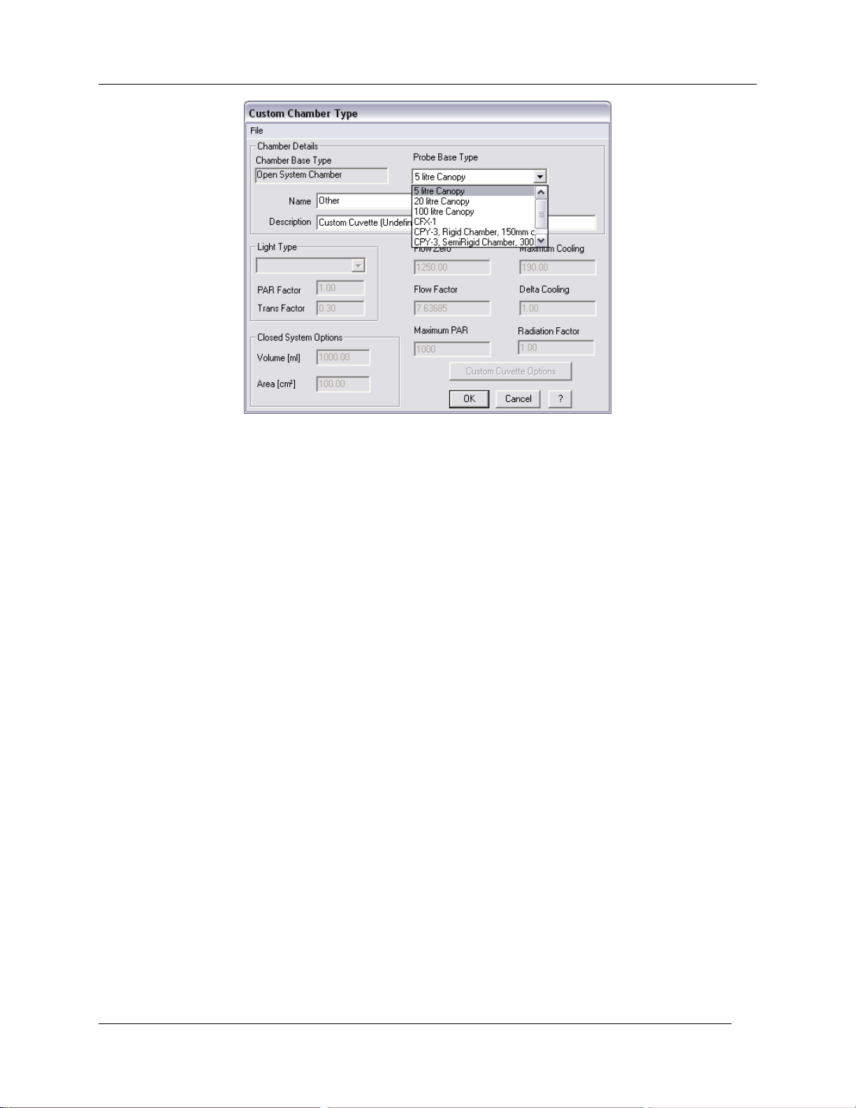
Light Type
System Setup and Operation
In the „Light Type‟ list select from correct Light Unit (or light source) used with your cuvette (Ambient, LED
or Tungsten Halogen). Available options are based on Probe Type and Chamber/Cuvette Type selected.
Leaf Temperature (T
leaf
)
Depending on cuvette/chamber selection - IR Sensor/Energy Balance/Thermistor. The IR sensor is only
available with modern PLC6 (U) and PLC5 (B) Automatic Leaf Cuvettes. Energy Balance is provided as
secondary choice.
Leaf Temperature Determination: Explanations
Accurate measurement of leaf temperature (T
conductance. In determining the water vapor pressure gradient between the leaf and the outside air (the
driving force for transpiration) the air inside the leaf is assumed to be saturated at the leaf temperature.
T
is determined by the balance between energy absorbed by the leaf from incident radiation (visible and
leaf
short wave infra-red), energy lost in the evaporation of water, energy either gained or lost in long wave
radiation to the surroundings and in conduction with the surrounding air. There are three commonly used
methods used to measure T
which CIRAS-2 makes available to the user depending on the type of
leaf
cuvette.
1. Energy Balance
2. Thermistor
3. Infrared sensor (IR)
Energy Balance
All “Manual” and “Automatic” type leaf cuvettes have this option available, and we recommend this in
preference to the “Thermistor” method described below. This method of T
reasonably good average for T
. As mentioned above, the energy balance of the leaf determines the
leaf
temperature, so the more accurately we determine these components the better we can calculate the
temperature.
) is essential for the determination of stomatal
leaf
measurement produces a
leaf
CIRAS-2 Operator's Manual Version 2.04
- 45 -
Page 48

System Setup and Operation
First, we convert the radiation falling on the leaf into the energy absorbed. We measure the visible quanta
(PAR) and using the TRANS factor (see more at Energy Factor on page 49) convert this to energy
absorbed. The value of TRANS depends on the energy distribution with wavelength of the source; the
position of the PAR sensor (inside or outside the cuvette); the transmission characteristics of the cuvette
windows; the reflection characteristics of the leaf surface; and the absorption characteristics of the leaf.
From the humidity measurements and flow rate, we can determine the energy lost in evaporation. From
the measurements of the boundary layer in the cuvette we can calculate the conductive heat exchanges
between the cuvette and air. By assuming that the cuvette wall temperature is the same as air
temperature we can calculate the radiation exchanges. Using all this information, we can calculate
average T
. See Calculations in Appendix 2. on page 153 for a detailed description.
leaf
Thermistor
Not recommended - we do however make it available for use with all “Manual” and some “Automatic” type
Leaf Cuvettes. This option is not available with the PLC6 (U) or PLC5 (B) Automatic Broad Leaf Cuvettes
as these cuvettes have an infrared temperature sensor fitted (See IR below).
Direct Leaf Temperature Measurement - Common Problems
A leaf temperature sensor making physical contact against the underside of the leaf will have at least 50%
of its area exposed to the air rather than the leaf. If it is covered to insulate it from the air, then the area of
leaf that is also covered will not transpire nor will there be energy exchanges with the air. It will therefore
be at a different temperature than other areas of the leaf.
Very small sensors have to be inserted in the leaf to affect an accurate and direct measurement. But this
will cause local damage to the leaf, affecting transpiration and therefore the temperature. Heat conduction
along the wires that are in the air, to/from the sensor also has a significant effect. IR photography of
leaves also shows significant patchiness in leaf temperature.
Infrared (IR)
Only the PLC6 (U) and PLC5 (B) Automatic Broad Leaf Cuvette have this option available as it features an
IR sensor fitted to the base of the cuvette head.
If we can determine the net radiation exchanges between the leaf and a sensor of known temperature
then we can calculate the leaf temperature. The sensor consists of a thermopile with an upper blackened
absorbing surface facing the underside of the leaf. The temperature of the base of the thermopile is
measured. If the thermopile and leaf are at the same temperature then there will be no net energy
exchange, therefore no temperature gradient across the thermopile and no signal. If the leaf is cooler
then the thermopile surface will also cool relative to the base and vice-versa. The thermopile output is
calibrated against leaf simulants of known temperature so we can determine the leaf temperature. The
one limitation of this method is that the field of view of the sensor must be completely filled with
leaf material. Given that the area of the PLC6 (U) and PLC5 (B) Automatic Leaf Cuvette is very small,
most broad leaf types will completely fill the chamber making this method of leaf temperature
measurement the most accurate and recommended choice.
Please note: If the leaf does not completely cover the entire window area, (e.g. the PLC6 (U) 18mm
diameter circular opening in the center of the window), this method of leaf temperature measurement
MUST NOT BE USED. We then recommend that you select the Energy Balance method.
Leaf Area
User Specified. Cuvette/head plate selection defaults a defined Leaf Area value, for example, the PLC6
(U) cuvette will default to 2.5 cm2 (18 mm diameter insert). The size and shape of the leaf may be
important in your decision as to which cuvette head plate to use (1.75 cm2, 2.5 cm2, 4.5 cm2). Leaf area
also has a significant effect on final calculations of photosynthesis. However, if recalculation of data is
required, this can be done fairly easily. See Recalculate Data on page 81.
CIRAS-2 Operator's Manual Version 2.04
- 46 -
Page 49

System Setup and Operation
Boundary Layer Resistance
Enter the correct boundary layer resistance value from the green and white test label found on your
cuvette handle. Methods used to determine boundary layer resistance of automatic leaf cuvettes using a
pseudo-leaf can be found in the PLC5-6 Auto Cuvette Operation Manual.
Percent of Stomata on Upper Leaf Surface
Adaxial/abaxial stomatal ratio defaults to 50% - you may update this for known species-specific values.
Zero/Diff Bal Mode
1. Zero. CO2 / H2O free air is passed through the analyzer sample cells and the values are
recorded. Under these conditions there is no IR absorption and the readings from the detectors
are at maximum. CIRAS-2 uses this information to correct for most factors that cause IRGA drift.
2. Diff Bal. The reference (sample) air is passed through both the reference and analysis sample
cells and the offset values are recorded and applied to subsequent measurements. This
compensates for any differences between the cells and ensures that the reported differences in
concentration are accurate.
Please note: It is very important that the Zero Absorber Columns (Columns 1 and 2) are fresh and that
the reference CO2 concentration is steady when the Diff-Bal is performed.
Manual with Warnings
Perform manual Zeroes and Diff Bal if desired. CIRAS-2 will prompt you when it determines a Zero or Diff
Bal is required.
Automatic
Zeroes and Diff Bal are performed automatically at regular intervals. Leaving „Zero/Diff Bal Mode‟ set to
„Automatic‟ is recommended until you become more familiar with CIRAS-2 operation.
Auto Zero with Stored Diff Bal
This mode allows for working over a range of CO2 concentrations without the need for Diff Bal. Prior to
recording data, the Diff Bal is performed over the anticipated CO2/ H2O range at approximately 100 ppm
CO2 / 3 mb H2O intervals. The values are then stored for use during measurement.
Manual Without Warnings
Perform manual Zeroes and Diff Bal if desired. CIRAS-2 will not display a prompt.
Choice of Zero Mode – Recommendations
Manual With Warnings: When CO2 concentrations are being regularly changed (i.e. CO2 response) and
greatest accuracy is required. The user can then judge when the CO2 concentration is steady before
selecting Zero.
Automatic: Ideal for a series of measurements that are conducted at the same CO2 concentration.
Auto Zero with Stored Diff Bal: When CO2 concentrations are being changed and the quickest response
is required. Use during A/Ci curves to inform CIRAS-2 of expected range of CO2/H2O concentrations.
CIRAS-2 Operator's Manual Version 2.04
- 47 -
Page 50
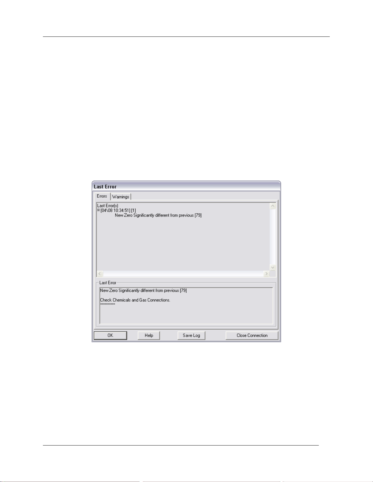
System Setup and Operation
Manual Without Warnings: Only recommended if the user is very experienced with gas exchange and
finds the warnings inconvenient. It is also useful where the Zero is under PC control.
Changes in Zero Readings
Whenever CIRAS-2 has been running for longer than 30 minutes, a set of analyzer A/D readings are
stored representing the Reference and Analysis CO2 and H2O values measured after an Automatic Zero
has been completed. Following a Zero, CIRAS-2 checks the new Zero against the stored values in 2
ways:
1. If the current and previous values differ by more that +/- 100, an Error Code 79 is generated („New
Zero Significantly different from previous [79]‟).
2. If more than 4 sets of Stored Zeros are present, CIRAS-2 checks the slope of the data. If the
slope falls out of an acceptable range, an Error Code 78 is generated („Zero Showing Progressive
Change [78]‟).
These messages could simply be the result of a Zero performed when the chemicals are not fresh, and
then the next Zero performed with fresh chemicals. It may also be an indication that a column has not
been replaced properly. Although this may cause the user concern, if the A/D values in Stored Zeros (see
Stored Zeros on page 134) do not differ by much more than 100, there probably is not much of a problem.
If the A/D values differ by more than 100, then it could be a symptom of a greater problem. Ensuring that
the chemicals are replaced regularly, the absorber columns are inserted correctly, and the Zero is
performed under stable conditions will help to avoid this error message.
CIRAS-2 Operator's Manual Version 2.04
- 48 -
Page 51

System Setup and Operation
Analysis Flow
This is the flow rate through the analyzer sample cells. Refers to the rate at which the analyzer samples
the analysis air and is user adjustable between 50-100 cm3 min-1. For normal leaf gas exchange the
recommended operational flow rate is the default setting (100 ml min-1).
Averaging Limit
Outputs from CIRAS are subjected to an averaging process. The linearized current reading is differenced
with a stored average reading. If the difference exceeds the Averaging Limit then the current reading
replaces the average, otherwise the current reading is incorporated into the average. The default
Averaging Limit is 30 units, corresponding to 3 ppm for CO2 and 0.2 mb for H2O. If set to 1, averaging is
disabled giving instantaneous readings. The averaging band is increased as the averaging limit is
increased, up to a maximum of 999 units. The Enable Averaging box must be checked.
System Setup
Probe Type
Air Supply On
Checking/unchecking this box turns the internal cuvette air supply unit on and off. Setting the Air Supply
pumps to Off will result in the setting of CO2 and H2O set points being disabled as the flow is assumed to
come from a separate source ( i.e. an external air supply).
Cuvette Flow
Flow rate to the cuvette is dependent upon cuvette type used with CIRAS-2. If „Air Supply‟ is off, the
maximum flow is 2500 ml min-1, if „Air Supply‟ is on the maximum is 470 ml min-1. Cuvette Flow must
always exceed the analyzer sampling rate by at least 50 ml min
chamber.
-1
to ensure positive pressure in the
Light Type [ _ ]
PAR
Energy Factor
Default light transmission coefficient determined by the Light and Chamber Type. User specified for
custom chambers. Refer to CIRAS-2 Settings for Leaf Cuvettes and Probes on page 152 of this manual.
Check „Use Sensor‟ (on chamber) to measure PAR or enter a value if using an external light source. If
checked, the PAR sensor on the chamber is used to determine PAR (with or without a light unit attached).
Please note: if a PP Systems‟ light unit is used and „Use Sensor‟ is not checked, the light unit will turn off.
This option will be enabled or disabled depending on the Accessory and Light Type selected.
Value
If disabled, CIRAS will use the entered PAR value in its calculations.
CIRAS-2 Operator's Manual Version 2.04
- 49 -
Page 52
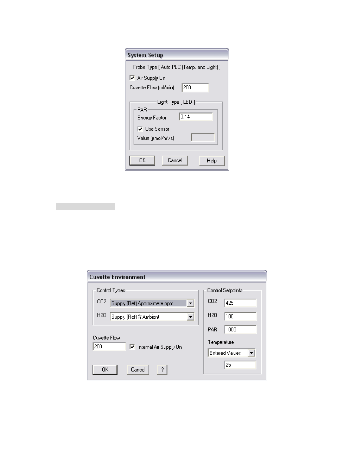
System Setup and Operation
Cuvette Environment
Click Cuvette Environment to enter baseline settings and values of environmental control variables that
define conditions inside the leaf chamber. These settings will be in effect each time you launch the RCS
program under the current Set and Parameters files, and whenever you exit the Recording Mode, where
you may be using different values. Control values associated with Cuvette Environment may be
changed at any time except during Response Curve recording. CIRAS-2 control variables available with
the PLC6(U) automatic cuvette and LED light unit are: CO2, H20, PAR, temperature and flow rate.
Additional options exist to control CO2, H20 and temperature in ways that allow greater flexibility and
convenience during measurements.
CIRAS-2 Operator's Manual Version 2.04
- 50 -
Page 53

System Setup and Operation
Control Types
CO2 (0–2000 ppm)
Selections available from the „CO2 Control Types‟ dropdown list:
1. Supply (Ref) Approximate ppm
The actual Reference gas (gas stream entering the leaf chamber) control value achieved will be
approximately that of the entered value. CIRAS-2 should control CO2 concentration to within
approximately 30 ppm of the value you enter in the „Control Setpoints‟ field (assuming fresh chemicals and
CO2 source, proper gas connections, and good zeroing).
2. Supply (Ref) Set ppm
The Reference gas control value will be within 1 ppm of the set value.
3. Cuvette (An) Set ppm
The Analysis gas (gas stream exiting the leaf chamber) control value will be within 2 ppm of the set value.
About CO2 Control Types
Control Types 1 and 2 are recommended for the most efficient control of CO2 concentration, as neither is
influenced by the leaf response to chamber conditions. Control Type 1 allows rapid CO2 concentration
changes and therefore faster overall leaf stabilization times, but the user must be aware to expect lower
precision in CO2 control. Also, the absolute difference between the entered CO2 value and the actual
Reference gas value can change with depleted chemicals and improperly conducted Zeroes. Control
Type 2 provides precise control. However, changing the CO2 concentration using Control Type 2 results
in longer delays (up to several minutes) while the concentration stabilizes. In both cases measurements
should be suspended until the system is stable, as these data will be invalid.
H2O (0-100% or 0 mb-Dewpoint)
Selections available from the „H2O Control Types‟ dropdown list:
1. Supply (Ref) % Ambient
This H2O Control Type tracks humidity of the Reference air and allows you to mirror it precisely in the
cuvette, i.e. 0-100% of ambient (Reference) humidity. Using this you can set the leaf chamber humidity
level to some lower fraction of Reference air humidity. For example, say that there is 60% RH (or 14.0 mb
at 20 °C and standard pressure) in the Reference gas stream entering the leaf chamber. If you enter a
H2O Setpoint value of 50 (%) CIRAS-2 will rapidly dehumidify the gas stream entering the leaf chamber
such that RH in the chamber will be quickly lowered to 30% (or 7.0 mb).
2. Supply (Ref) Set mb
The Setpoint value is entered in mb (control range of 0-75 mb) and control of H2O partial pressure of the
Reference air should be within 0.1 mb. Lowering the mb value of the Reference air will rapidly dehumidify
the gas stream entering the leaf chamber such that RH in the chamber will decrease rapidly.
3. Cuvette (An) % RH (vs. Leaf T)
The Analysis air H2O is controlled to give the set % relative humidity in the cuvette with reference to leaf
temperature. Initially, the humidity will be set to 50% of ambient and control will not commence for several
minutes while the software determines the ambient humidity. Changing the set humidity value will result in
an immediate response as the software is continuously updating the value. However, changing the H2O
Control type may result in the same delay.
CIRAS-2 Operator's Manual Version 2.04
- 51 -
Page 54

System Setup and Operation
4. Cuvette (An) Set mb (0-Dewpoint)
The An H2O is controlled to within 0.1 mb of the set value. Because of the good stirring in the cuvette, this
should be the concentration experienced by the leaf. Initially, the humidity will be set to 50% of ambient
and control will not commence for several minutes. This is because the software is determining the
ambient humidity. Changing the set humidity value will result in an immediate response as the software is
continuously updating the value. However, changing the H2O Control type may result in the same delay.
5. Leaf to Cuvette VPD
Analysis H2O is controlled so that there is a constant Vapour Pressure Gradient (specified in mb) between
the leaf tissue (assumed to be saturated at leaf temperature) and the cuvette air. Initially, the humidity will
be set to 50% of ambient and control will not commence for several minutes. This is because the
software is determining the ambient humidity. Subsequently, changing the set value will result in an
immediate response as the software is continuously updating the value. However, changing the H2O
Control type may result in the same delay.
About H2O Control Types
As with changes in CO2 concentration, rapid changes in RH within the leaf chamber are wholly artificial
(from a physiological standpoint) and measurements should be suspended until stable conditions prevail.
Control Types 3, 4, 5 are dynamic, responding to feedback from the leaf. Leaf responses to changing
cuvette conditions may result in automatic adjustments to flow rate, which will require additional leaf
equilibration times.
Determination of Actual Ambient RH
Please note: Reference air is conditioned along its path to the leaf chamber by passing through soda
lime, which removes CO2, but adds water vapor to the gas stream. After next passing through the water
vapor equilibrator up to 10 mb of water vapor is removed, but RH in the air sample is still greater than
outside ambient RH.
To determine the actual ambient relative humidity (in the leaf‟s undisturbed environment) you can simply
open the cuvette and observe the RH reading in the display. For a slightly faster and more accurate
reading temporarily remove the AN IN gas connection, allowing outside air to be directly drawn through the
Analysis side of the IRGAs. Temporarily remove the REF IN gas connection to see the corresponding
ambient water vapor value in mb Once you have determined and noted the true ambient RH (or water
vapor in mb) you can change your settings accordingly. Remember to reconnect the gas connections
before proceeding.
PAR
Depending on cuvette type, enter a PAR Control Setpoint from 0-2,000 µmol m2 s-1.
Cuvette Flow
Appears as above (see System Setup on page 49.)
CIRAS-2 Operator's Manual Version 2.04
- 52 -
Page 55

System Setup and Operation
Temperature
Track Ambient
Cuvette temperature (Tc) control tracks ambient temperature as measured by the sensor in the base of
the cuvette handle (PLC5-6).
Entered Values
If selected, enter a temperature value in the field below. Value must be within the range of 8 oC below
ambient to 45 oC. Please note: Be aware of possible condensation inside the cuvette if warm air passing
through the system is suddenly cooled by the Peltier unit in the cuvette.
None
Cuvette temperature control disabled.
Which Control Type Should I Use?
For most field work involving a large number of leaves, it is advisable to make the measurements as
rapidly as possible so that measurements are being made on leaves adapted to field conditions.
Therefore, we would recommend selecting Supply (Ref) Approximate ppm for CO2 and either Supply
(Ref) % Ambient or Supply (Ref) Set mb (0-Ambient) for H2O. With most leaf cuvettes, stable readings
should be possible within a one minute time interval using these Control Types.
For A/Ci and light response (A/I) curves in the laboratory and field, we recommend selecting Supply (Ref)
Approximate ppm for CO2 and either Supply (Ref) % Ambient or Supply (Ref) Set mb (0-Ambient) for
H2O.
If performing a Light Response:
1. Set the CO2 to a high, non-limiting value.
2. Set the light to the highest level required.
3. Wait for equilibrium and then reduce the light intensity in steps.
If performing a basic CO2 Response:
1. Start off with a low CO2 concentration and high light intensity until equilibration. This will open the
stomata to their maximum.
2. Increase the CO2 in steps to the maximum desired value.
If performing both a light response and a CO2 response on the same leaf, start off with a CO2 response
followed by the light response, as described above.
Customized Operation of CIRAS-2 with Ambient CO2
Especially for field work, you may wish to measure gas exchange without actually controlling CO2
concentrations from CIRAS-2, using instead the naturally fluctuating diurnal CO2 concentrations in
ambient air. To do this:
Empty all soda lime from Absorber Column 3 and replace the empty column in the manifold. Remove only
the molecular sieve from Absorber Column 4 and replace. (Both soda lime and molecular sieve remove
CO2 from the gas stream). Next, attach a length of butyl tubing (supplied) to the AIR IN gas port and
shield it from sources of CO2 such as your breath and engine exhaust. AIR IN must also be protected
CIRAS-2 Operator's Manual Version 2.04
- 53 -
Page 56
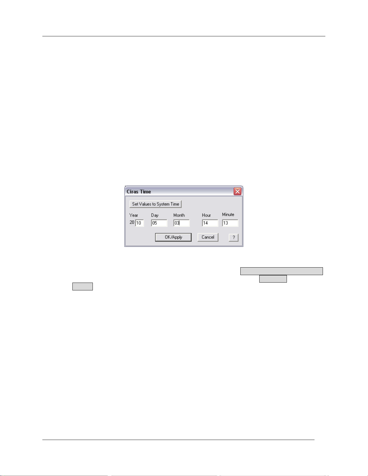
System Setup and Operation
from wind and sudden pressure changes. Create a “smoothing volume” such as a large plastic container
or sealed plastic bag and place the open end of the AIR IN gas line inside the smoothing volume. Finally,
remember to leave the CO2 holder/regulator assembly in place in CIRAS-2 either with no cartridge or with
an exhausted CO2 cartridge.
Customized Operation of CIRAS-2 at Humidity Levels Above Ambient
If you desire to work at humidity levels above ambient, you can do so as follows:
Ensure that Absorber Column 3 (as labelled on the bottom of CIRAS-2) is filled with new soda lime that
will humidify the air. Next, carefully remove and cover the water vapor equilibrator with clear plastic wrap
so it is isolated from ambient. Replace the equilibrator in the manifold.
Or
Carefully remove and cover the water vapor equilibrator with moist filter paper and reattach it to the
manifold. In very hot dry conditions you can also cover the filter paper in clear plastic wrap to minimize
evaporation.
CIRAS-2 Time
CIRAS-2 can be set to match the exact date and time of the PC (integral PC or Lab PC) or to a different
date and time if required. To match the values to the PC, click on Set Values to System Time.
Otherwise, a different date and time can be set as required. Once set, press OK/Apply to accept the
settings or Cancel to return to the Settings dialog.
Please note that setting the CIRAS-2 Clock takes a few seconds. If the software detects that the CIRAS-2
clock differs by more than 1 hour from the UI or Pencentra clock, the CIRAS-2 time will be set to the UI or
Pencentra time automatically. This option is only available when CIRAS-2 is connected.
Analog Outputs
The 8 pin LEMO type socket labelled SIG OUT on the CIRAS-2 is used for the analog outputs. All outputs
have a maximum voltage of 5.0 V from a source impedance of about 60 ohms. Therefore, if external
resistors are used to drop the voltage, it is recommended that they exceed 10 Kohms in total.
CIRAS-2 Operator's Manual Version 2.04
- 54 -
Page 57
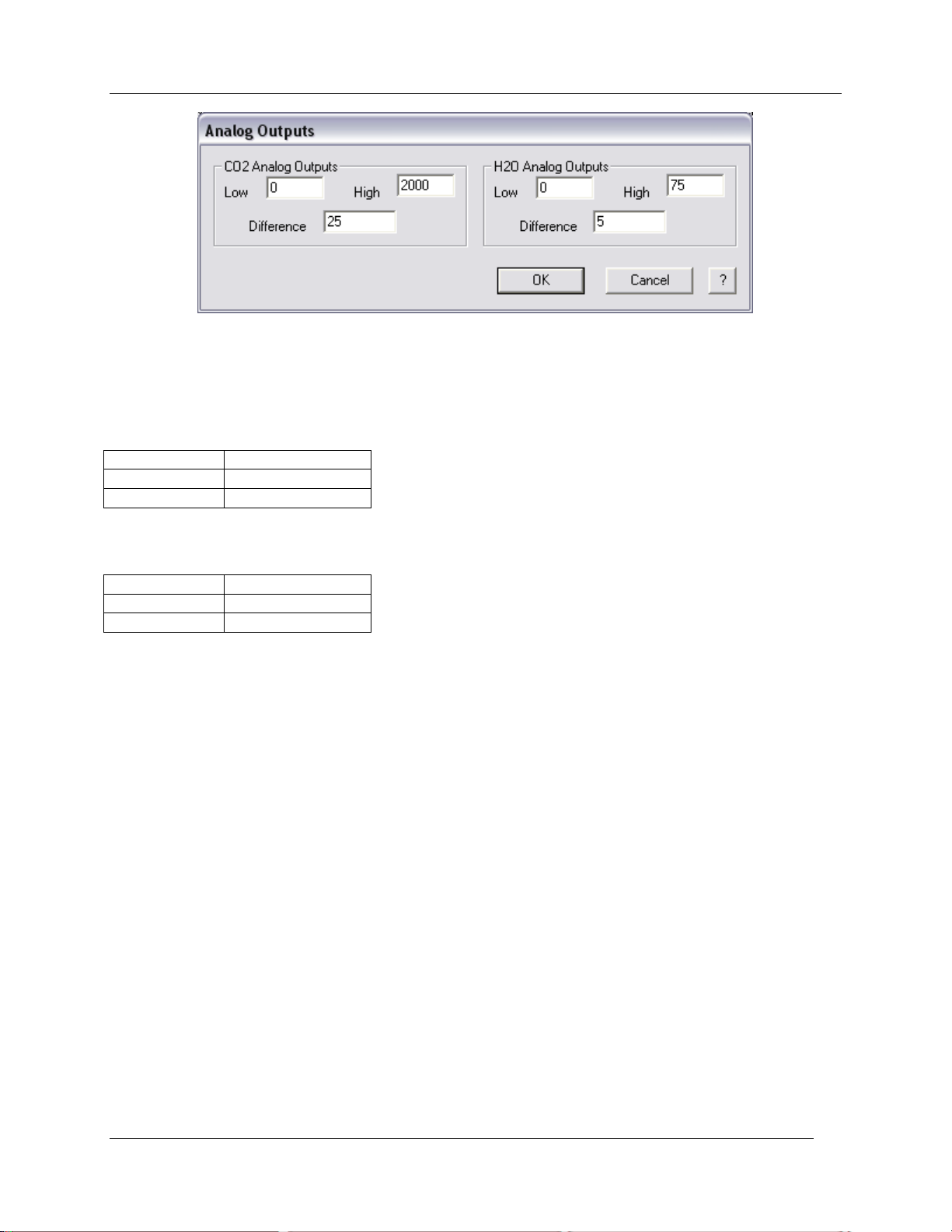
System Setup and Operation
Low
0 - 2,000 ppm
High
0 - 2,000 ppm
Difference
-25 - 999 ppm
Low
0 - 75 mb
High
0 - 75 mb
Difference
-5 - 75 mb
There are 4 analog output voltages in use corresponding to the absolute and differential CO2 and H2O
concentrations. The full range is 0-5 V with 8 bit (0-4% of FSD) resolution. To optimize the outputs, it is
possible to set the corresponding concentration ranges.
CO2 Analog Outputs
H2O Analog Outputs
For differential values (both CO2 and H2O), an output of 2.5V corresponds to a 0 differential. Output
values below 2.5V correspond to negative differentials (-) and values above 2.5V correspond to positive
differentials (+).
Examples of Analog Outputs
Example 1.
If:
CO2 Reference = 356 ppm
Low CO2 = 0
High CO2 = 2000
Then:
CO2 Reference Voltage Output = 356/2000 x 5.0V = 0.89 V.
Example 2.
If:
CO2 Reference = 356 ppm
Low CO2 = 300
High CO2 = 400
Then:
CO2 Reference Voltage Output = ((356-300)/(400-300)) x 5.0V = 2.8 V.
CIRAS-2 Operator's Manual Version 2.04
- 55 -
Page 58
System Setup and Operation
Example 3.
If:
CO2 Differential = +25 ppm
Range = +/- 50.0 ppm
Then:
CO2 Differential Voltage Output = 25/50 x 2.5 + 2.5 = 3.75 V.
Example 4.
If:
H2O Reference = 25.56 mb
Low H2O = 10 mb
High H2O = 50 mb
Then:
H2O Reference Voltage Output = (25.56-10.0)/(50-10)) x 5.0 V = 1.945V.
Automatically Update CIRAS
If checked, after clicking OK in the Settings dialog to save all changes to the PRM file, CIRAS-2 will
receive the new parameters. If this is not checked, CIRAS-2 will not be updated.
CIRAS-2 Operator's Manual Version 2.04
- 56 -
Page 59
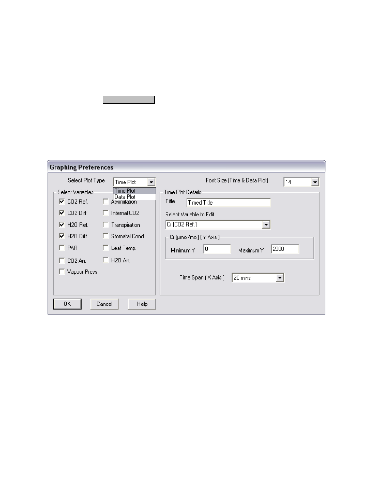
Graphing Preferences
Graphing Preferences
Before continuing you can select the variables you wish to view in the real-time display. You can access
this dialog in one of four ways:
1. Click Setup in the CIRAS main menu and open the Graphing – Preferences dialog box
2. Through the Graphing Options button in the Setup dialog
3. Right-click anywhere on the Time or Data Plots using RCS from a computer
4. Click anywhere on the Time or Data Plots with the mousepad and pointer using the UI.
Time Plot
From the „Select Plot Type‟ list choose Time Plot.
Select Variables
Choose up to four variables to display as continuous colored plots in the Time Plot. At least one variable
must be displayed. The list of variables automatically changes based on Accessories, e.g. variables
related to chlorophyll fluorescence while using the CFM module.
The available list is drawn from the parameters and variables seen in the Gas Exchange Measurement
Screen section (page 26), with two exceptions – CO2 An. (Analysis gas CO2) and H2O An. (Analysis gas
H2O). CO2 An. is simply CO2 Ref. + CO2 Diff. Likewise, H2O An. is the H2O Ref. + the H2O Diff.
Font Size
Choose the font size that best meets your needs – larger fonts for computer RCS display, smaller for the
UI when conducting research in the field.
CIRAS-2 Operator's Manual Version 2.04
- 57 -
Page 60
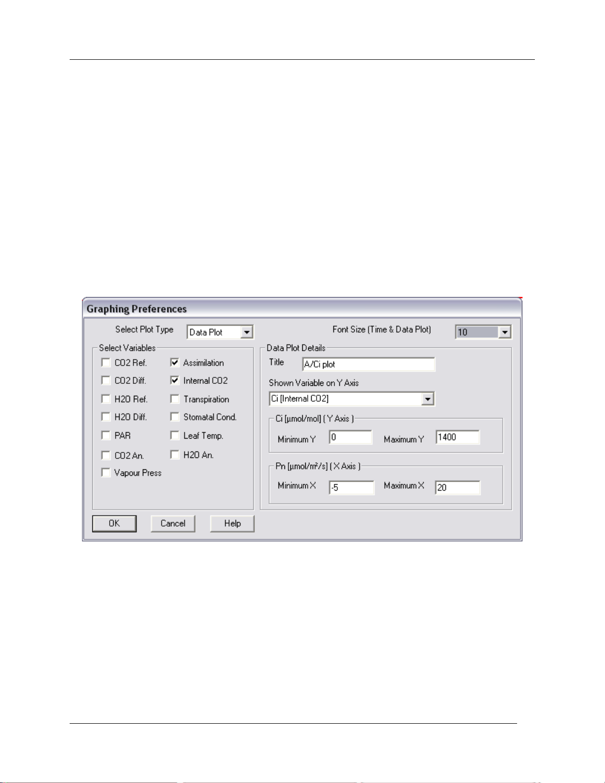
Graphing Preferences
Time Plot Details
Enter a description of the plot(s) if desired. This information will be saved with the data file.
Select Variable to Edit
The respective Y-axis scales of your chosen variables can be changed from defaults by choosing the
variable from the dropdown list. You will see a message if you set the scale outside of the min-max range.
Time Span
Choose your desired X-axis time span (10, 20 or 30 minutes).
Data Plot
From the „Select Plot Type‟ drop down list select Data Plot. This plot displays two variables only, plotting
data against data. Essentially, it allows you to view a real-time scatter plot, for example, an A/Ci plot.
Shown Variable on Y Axis
Choose which of the two variables to display as the response (Y-axis) variable, then set the min-max
scales for both selected variables as above.
CIRAS-2 Operator's Manual Version 2.04
- 58 -
Page 61
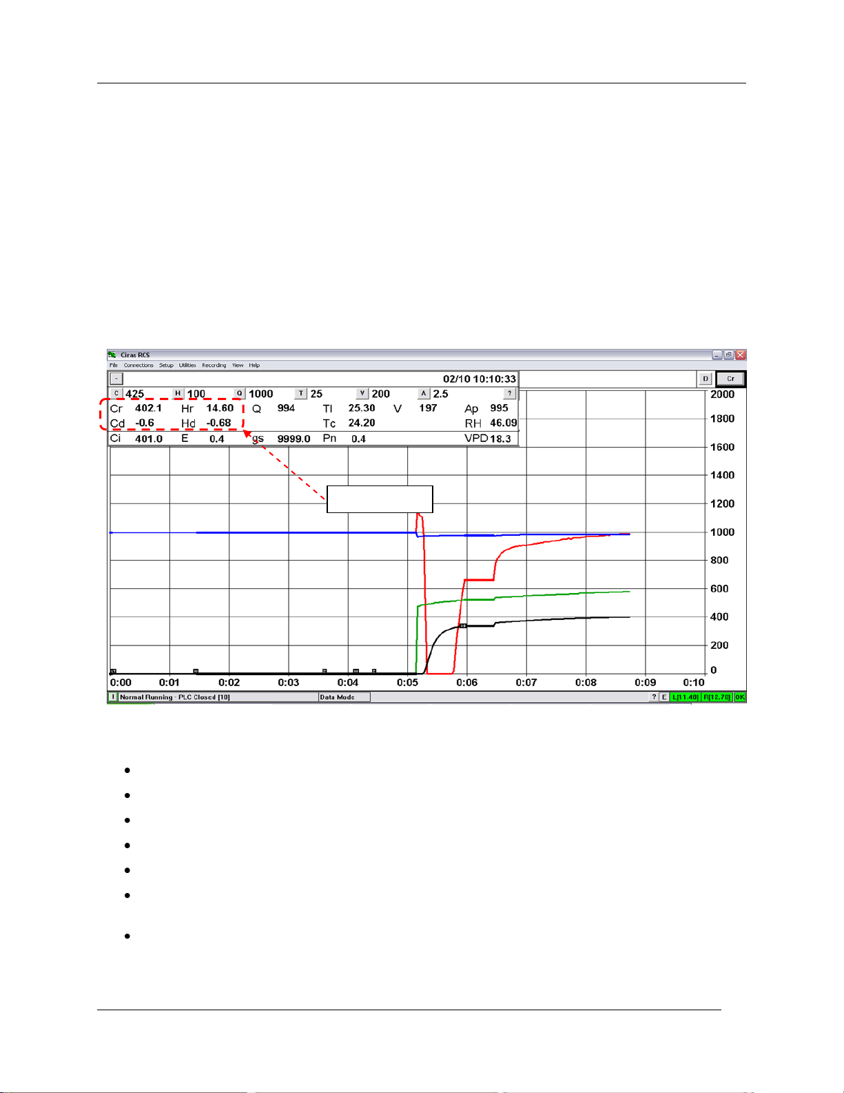
Observing and Recording Leaf Gas Exchange
Current
Observing and Recording Leaf Gas Exchange
Checking the System with an Empty Cuvette
With the cuvette closed and without a leaf inserted, you should conduct a routine test to ensure that all
values are stable and that the desired control settings are achieved. Stablity is easily observed by a flat
(horizontal) profile of the colored plots as they progress in time across the display screen. Select and
observe only the measured parameters associated with CO2 and water vapor from the „Select Variables‟
field: Cr, Cd, Hr, Hd.
Within several minutes a display similar to the one below should be observed, assuming the system has
been adequately warmed up and all steps in Preparations for Use (on page 18) have been carefully
followed:
Please note the following:
Cr (Reference CO2) value should be near your Setpoint value and stable (+/- 2 ppm).
Hr (Reference H2O) value should be at ambient and stable (+/- 0.2 mb).
Cd and Hd values should be stable at approximately 0.0 (+/- 0.5 ppm CO2 / 0.2 mb H2O).
Tc (Chamber Temperature) value should reflect your selected temperature value.
Tl (Leaf Temperature) value should be within approximately 1.5 °C of the Tc value.
Q (PAR) value should be near your Setpoint value (with attached LED light unit) or ambient (if no
light unit is not used)
Battery voltage for both the left and right batteries should be > 13.0 V if fully charged.
CIRAS-2 Operator's Manual Version 2.04
- 59 -
Page 62
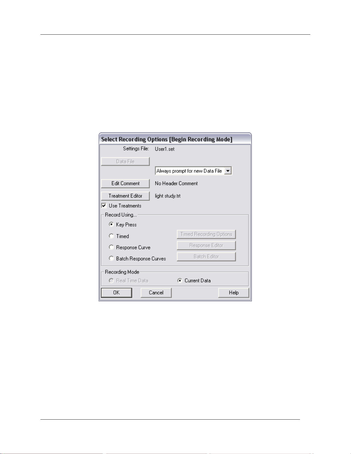
Observing and Recording Leaf Gas Exchange
Please note: The CO2 reference value (Cr) will not be exactly what you set if the CO2 Control Type
selected is (Supply (Ref) Approximate ppm). It should, however, be stable (fluctuating not more than +/- 2
ppm) at a value within approximately 15-30 ppm of the set value. Precise CO2 control is available to
within +/- 1 ppm of the set value by using the „Supply (Ref) Set ppm‟ Control Type.
The system is functioning properly if the above conditions are observed. If not, please refer to the
Troubleshooting Section of the CIRAS-2 Technical Manual available in the User section of our website.
Select Recording Options
To begin making measurements, select Recording – Begin from the CIRAS-2 menu bar.
There are four different methods available for recording data:
1. Keypress
2. Timed
3. Response Curve
4. Batch Response Curves
CIRAS-2 Operator's Manual Version 2.04
- 60 -
Page 63
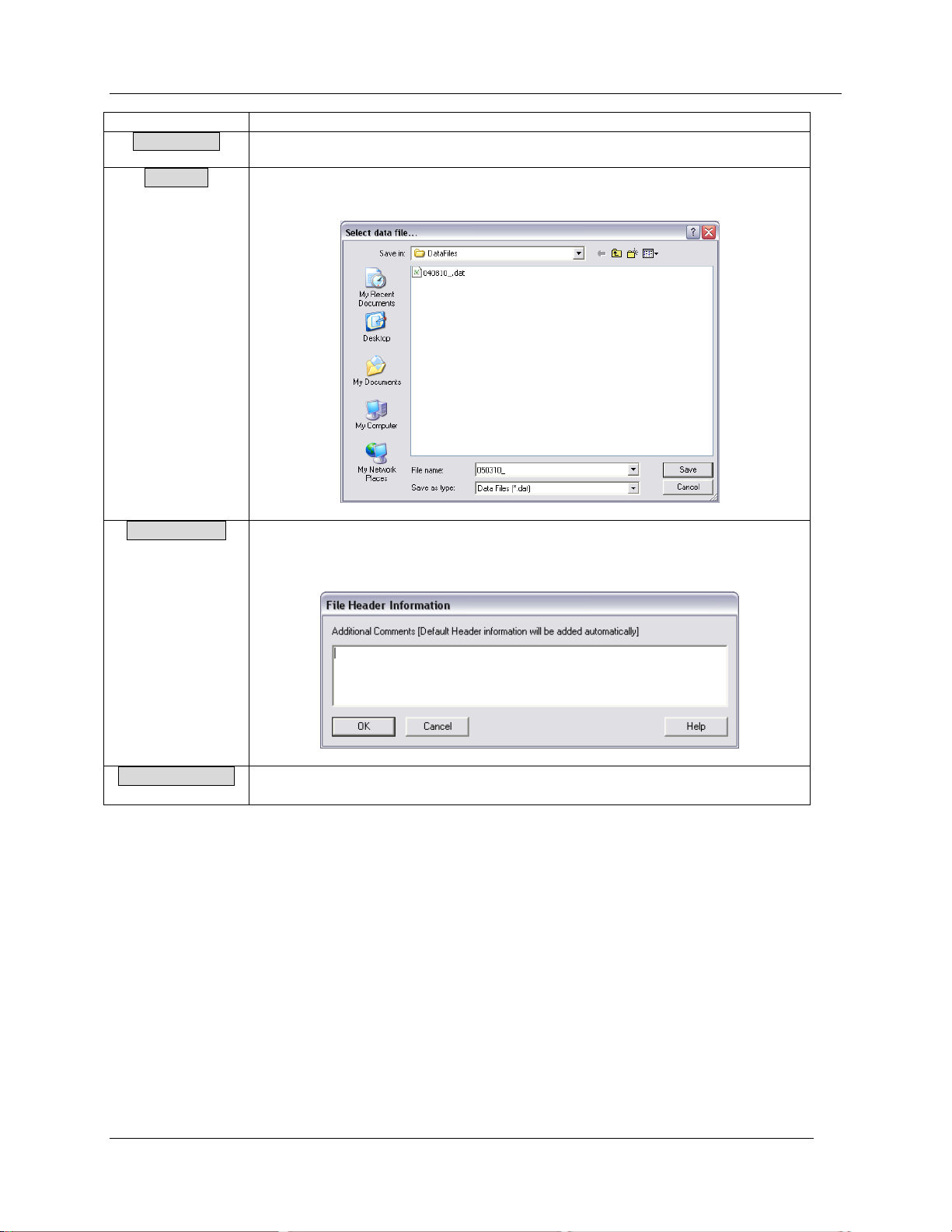
Observing and Recording Leaf Gas Exchange
Button/Field
Description
Settings File
Refer to Set File Options on page 41 for more details.
Data File
Create a new data file and enter a name in the File name box (.dat extension is
default). Measurements will be saved to this file.
Edit Comment
Additional comments can be saved with records if required. Comment is
placed at the beginning of the recorded data. Additional comments can be
added to the files throughout a recording session.
Treatment Editor
See detailed information below.
Treatment Editor
Treatment files (extension .trt) are provided to help identify records associated with a particular
experimental or sampling level, such as a plot, group, plant or pot. Each Treatment file can contain 10
Groups, and each group 10 Items.
Treatment Groups
These can be named as required and may be given further descriptions as necessary.
Treatment Items
Each item may be named and can have a unique description. Highlight the Default Item and check the
„Enabled‟ box to edit „Item Name‟. Enabling/ Disabling an item will determine whether it is displayed as an
option during recording. When Recording, each change of Treatment Item is recorded and all subsequent
CIRAS-2 Operator's Manual Version 2.04
- 61 -
Page 64
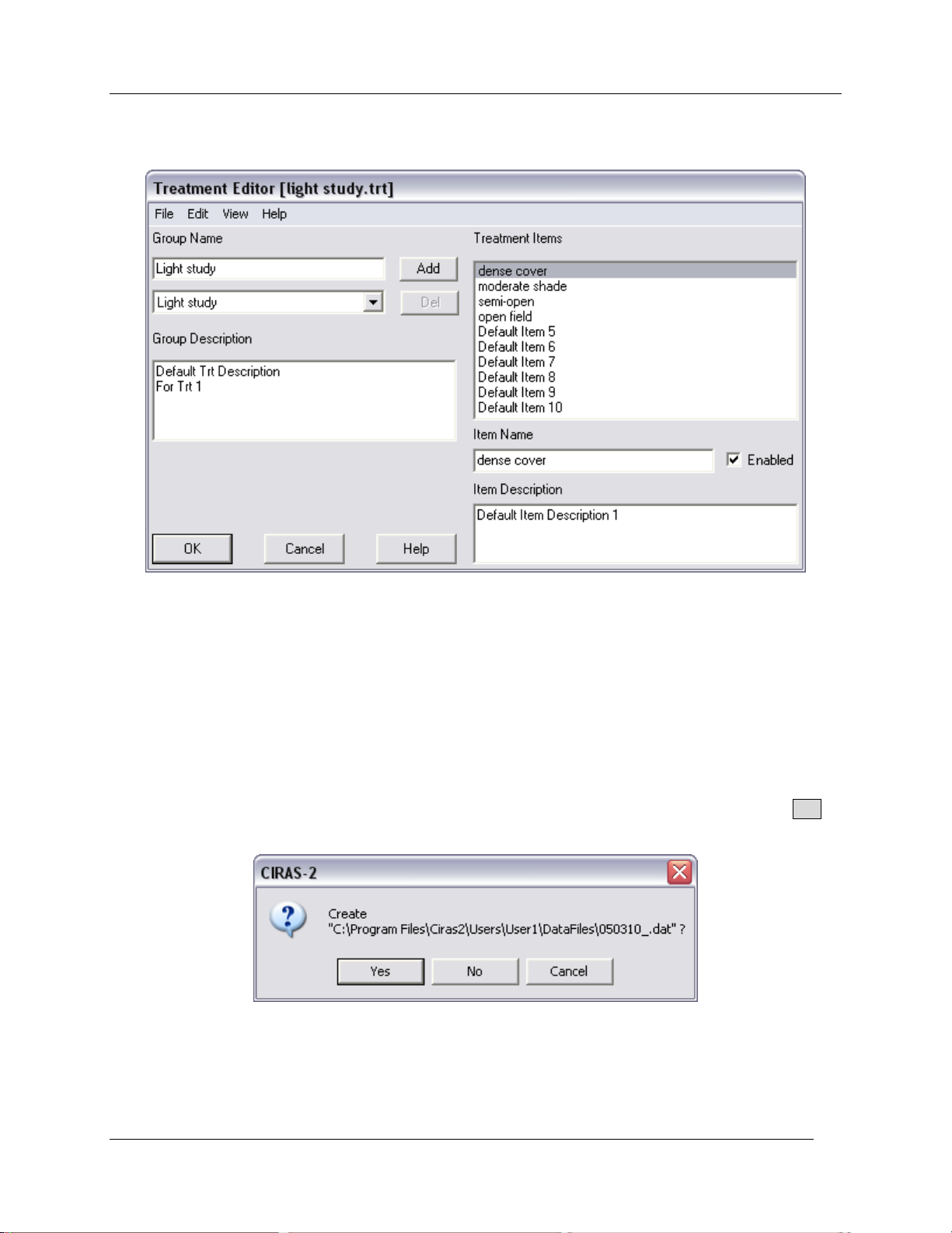
Observing and Recording Leaf Gas Exchange
records are assumed to relate to that item. If a Treatment file is not specified, a default set of “plots” are
used during recording.
Recording Mode
Defaults to „Current Data‟ in order for Setup – Settings to apply changes.
The following applies to all recording options:
The Select data file dialog box (as above) will appear for you to name the data file. In the Select
Recording Options dialog you can choose from three file saving options – „Append to Data File‟;
„Overwrite Data File‟; „Always prompt for new Data File‟. After naming the file you can either accept the
default file location on your computer or UI (example below), or choose a different location. Click Yes to
proceed to Recording Mode.
Please note: If CIRAS-2 is actively performing a Zero or Diff Bal, you may receive the following message
prior to naming the data file:
CIRAS-2 Operator's Manual Version 2.04
- 62 -
Page 65
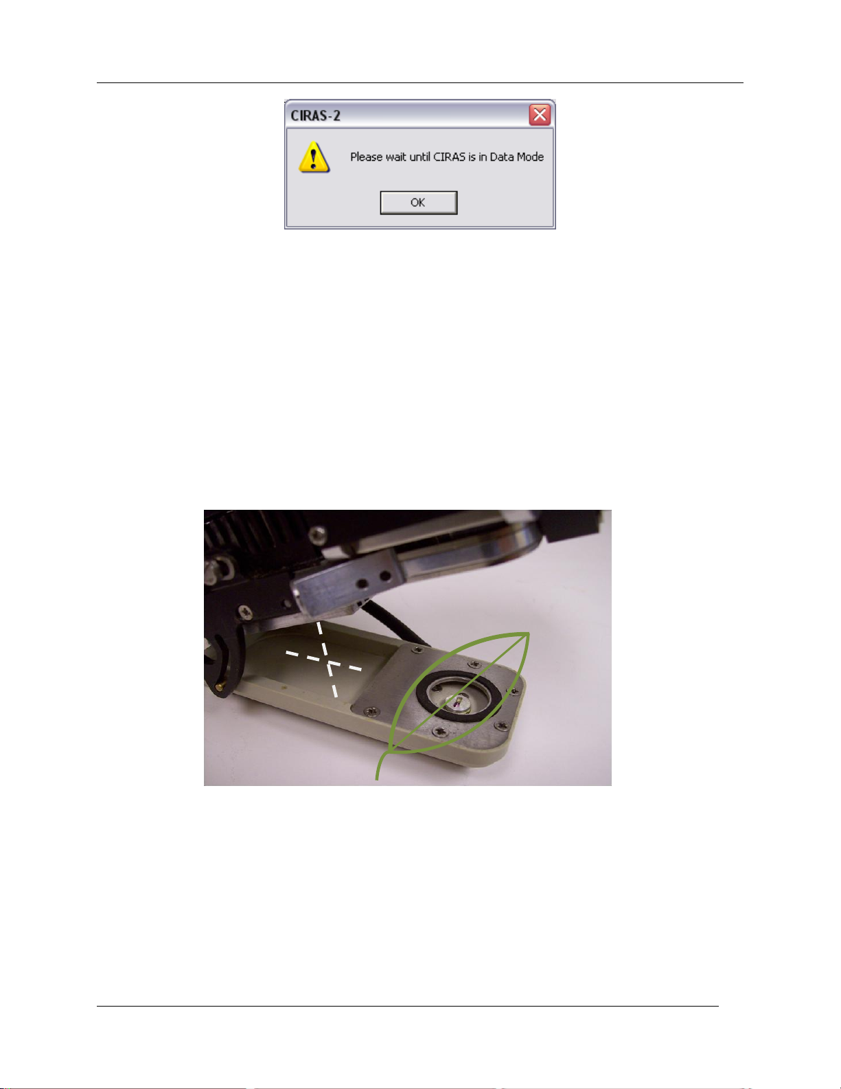
Observing and Recording Leaf Gas Exchange
If this occurs, simply wait until the completion of the Zero or Diff Bal check.
Placing the Leaf in the Cuvette
Choose leaves of sufficient size to completely fill the cuvette head opening around the gasket (as
illustrated below). The built-in IR leaf temperature sensor will return false values if light enters from gaps
around the leaf. In other words, the IR sensor must “see” only the lower leaf surface, otherwise you must
select „Energy Balance‟ as the default Leaf Temperature Determination type.
The leaf blade may extend beyond the foam gasket surrounding the opening. However, the leaf blade
must not extend beyond the back of the lower metal plate, i.e. into the back of the cuvette‟s lower jaw,
where part of the leaf will be crushed when the cuvette is closed. Try approaching the leaf from the side
with the open cuvette to avoid accidentally injuring the leaf in this way.
The cuvette tension screw is located beneath the cuvette open/close lever. Use a small hex wrench to
adjust the screw tension if needed to accommodate leaves of varying thicknesses. Turn the screw
counter-clockwise to tighten and clockwise to loosen the tension. Normally no more than ¼ turn in either
direction is needed. The goal is to establish a good seal without i) causing extreme pressure on the leaf
or ii) allowing ambient air to leak around the foam gaskets.
With the leaf enclosed in the cuvette you should quickly notice a series of dynamic leaf responses,
assuming ideal physiological conditions. Sub-stomatal CO2 concentration (Ci) will begin dropping, after
being initially higher than the reference CO2 concentration (Cr). When Ci<Cr there is an instantaneous
change in net photosynthesis (Pn) values from a negative rate (respiration) to a positive rate.
Simultaneously, the differential CO2 concentration (Cd) will go into negative values while differential
CIRAS-2 Operator's Manual Version 2.04
- 63 -
Page 66
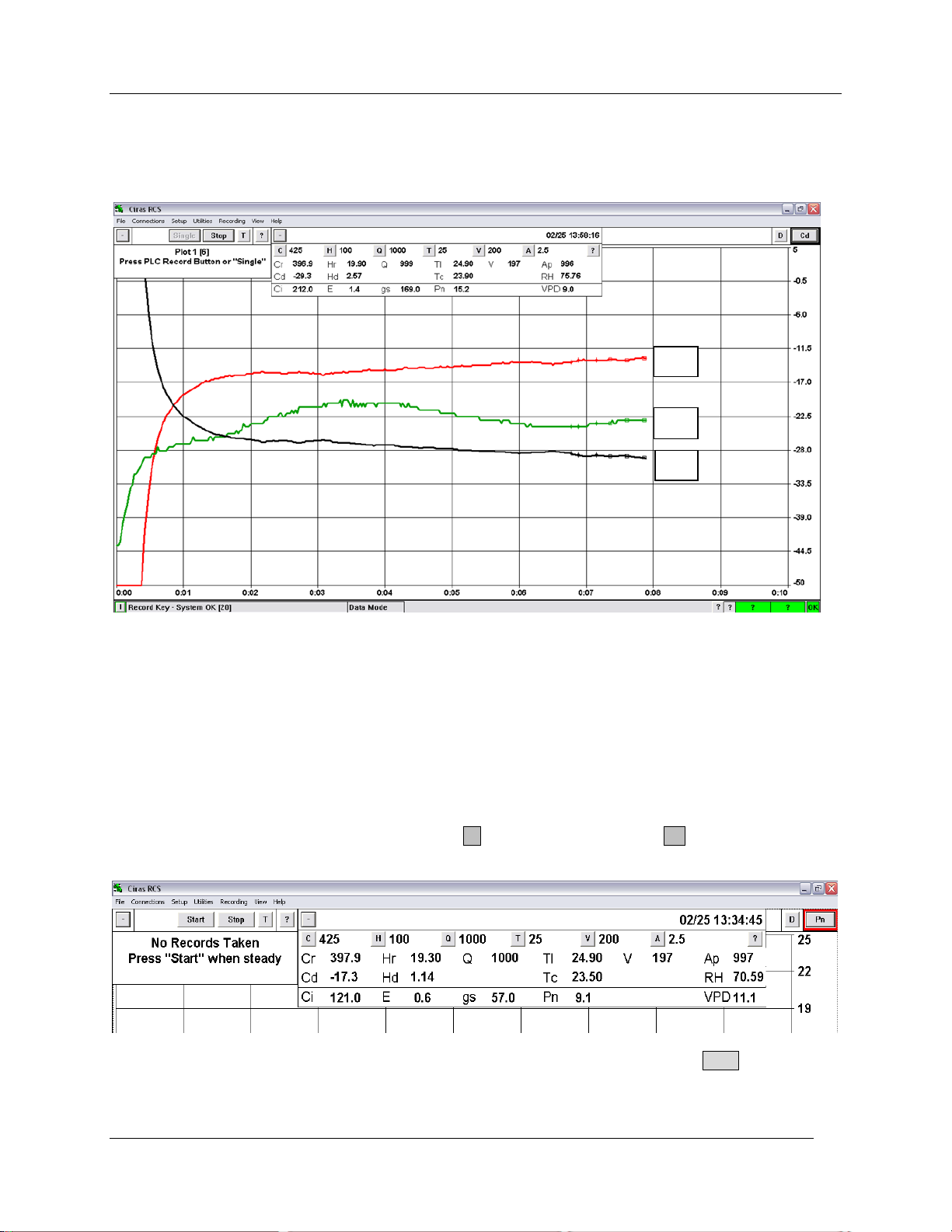
Observing and Recording Leaf Gas Exchange
Pn
Tl
Cd
humidity (Hd) becomes positive – the leaf is both fixing carbon dioxide and transpiring water vapor. As
seen in the figure below, Pn (red plot) and Cd (black plot) typically appear as near mirror images. The
green plot is the leaf temperature.
Note that some physiological variables, especially Pn, gs (stomatal conductance) and Cd will continue
changing as the leaf equilibrates (approaches a stable state) for approximately 45-60 seconds, and as
long as a few minutes. This depends largely on the preconditioned state of the plant relative to the
environmental conditions inside the cuvette. A useful illustration of this can be seen with a highly shadeadapted plant that is suddenly exposed to strong light intensities in the leaf chamber. In this case, delayed
gas exchange responses can be expected compared to a plant (or leaf) accustomed to more intense light
conditions.
In Recording Mode the CIRAS-2 display changes (upper section of display screen shown, below),
including a new window (upper left) containing Recording features as well as the now familiar Data
Display and Control features window. Click the - button to collapse or the + button to view either
window. You may need to adjust to a smaller font size to accommodate both windows.
When readings are stable and you are ready to begin measurements, click the Start button in the
Recording window. Depending on the state of your CIRAS-2, the instrument may perform a Zero and Diff
Bal. You may also take this opportunity to adjust your Graphing Options, for example, by selecting one or
CIRAS-2 Operator's Manual Version 2.04
- 64 -
Page 67
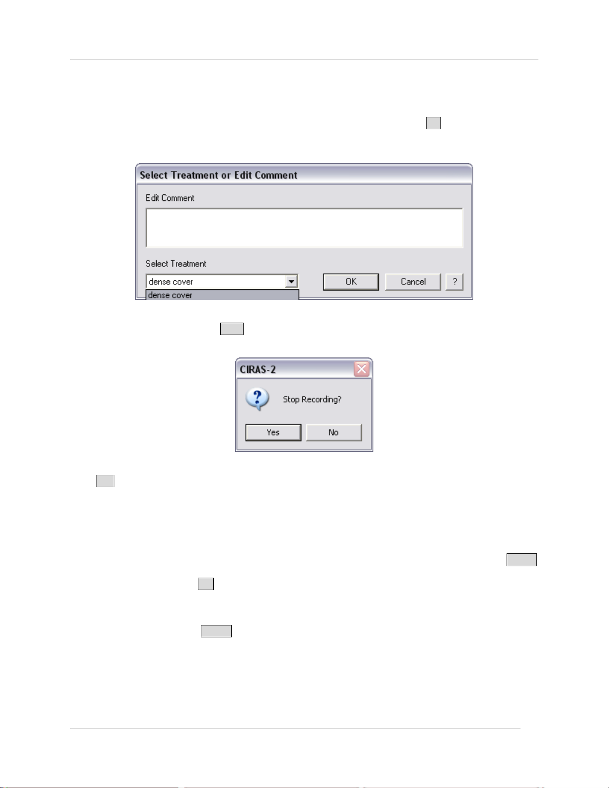
Observing and Recording Leaf Gas Exchange
more of the calculated physiological variables. In the sample screen (above) the currently active plot is Cd
(black) with the Y-axis scale set to +5 to -50, to capture both respiration (positive differentials) and
photosynthesis (negative differentials).
To include additional information about your experiment or treatment click the T button and enter the
information by selecting a particular “Treatment” associated with the measurement.
To end measurements, press the Stop button. The following will be displayed:
Click Yes to terminate measurements.
Keypress Recording
For many leaf gas exchange measurements, such as those made in the field and under dynamic light
conditions, this method of recording is most practical. Using this method you can record measurements in
rapid succession with either the thumb record switch on the cuvette handle or by clicking the Single
button in the CIRAS-2 Recording Mode screen. To begin manually recording data, click in the circle next
to „Key Press‟ and then click OK.
In Keypress Recording mode the appearance of data markers in the Time Plot is different depending on
the source of the record: in the image below the first 3 records (circles with a vertical hash line) on the
plots, were taken by clicking Single – the next 3 records (boxes) were taken with the thumb record switch
on the PLC6(U) cuvette.
CIRAS-2 Operator's Manual Version 2.04
- 65 -
Page 68
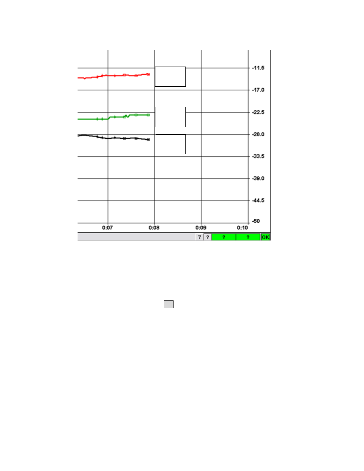
Observing and Recording Leaf Gas Exchange
Pn
Tl
Cd
Timed Recording
This option allows indefinite data collection that can be programmed to run until the operator manually
stops recording. It may be used unattended on a single leaf for long periods, or the user may choose to
pause recording to either change Control Setpoints or sample different plants or leaves.
Again, select Recording - Begin from the CIRAS-2 main menu. In the Select Recording Options dialog
click in the circle next to Timed and then click OK. There are two Timed Recording Options:
1. Recording single measurements
2. Recording blocks of measurements
Both options have an initial Settle Time to allow for stabilization and a forced Zero before recording
begins. Both options can include recording only after a Steady PN (assimilation rate) has been reached,
allowing you to determine your own acceptable level of variability associated with the plant or species of
interest.
CIRAS-2 Operator's Manual Version 2.04
- 66 -
Page 69
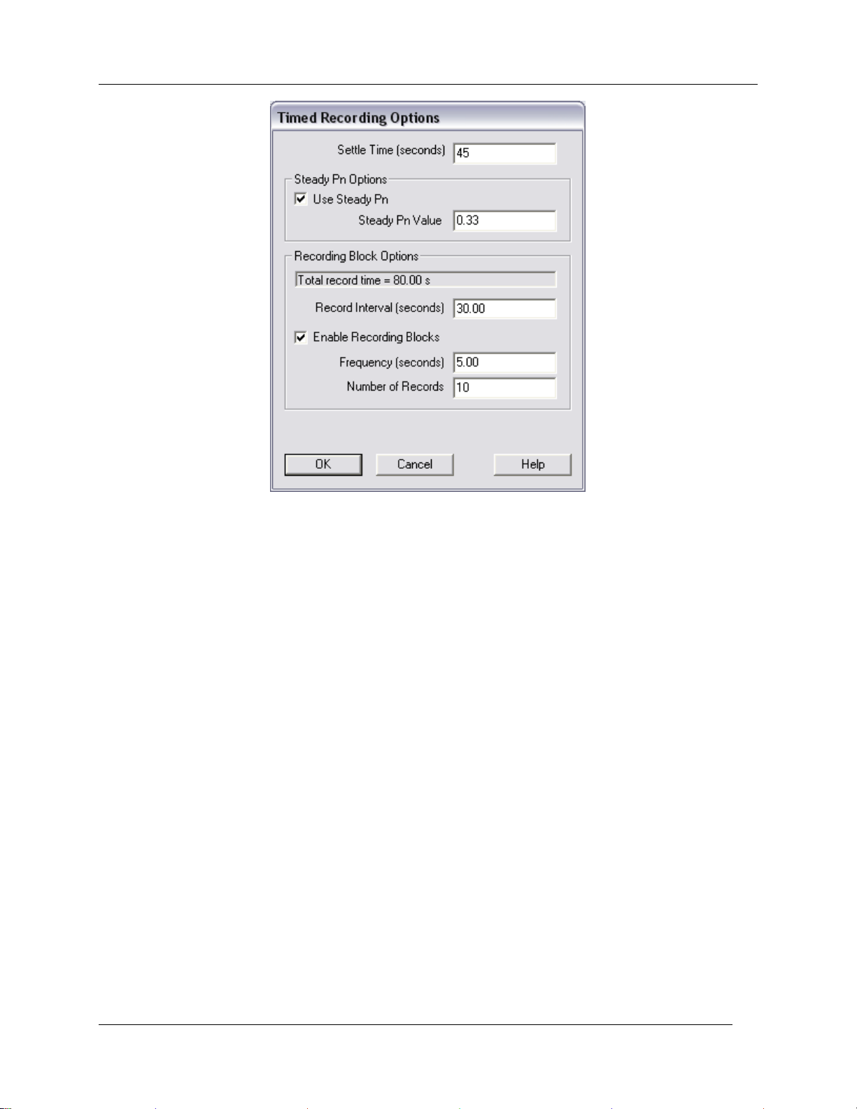
Observing and Recording Leaf Gas Exchange
Settle Time (Seconds)
The minimum amount of time (seconds) required to stabilize before recording. After the settle time has
been achieved, a record may be taken.
Steady Pn Options
Use Steady Pn
Requires that assimilation rate is stable by +/- your chosen value over a defined time (approximately 11
seconds). Once this condition has been met, the record(s) will be taken. Select to enable this function.
To disable, deselect it.
Steady Pn Value
Enter an acceptable value (+/-) for Pn variability before data can be recorded.
Recording at Pre-set Intervals
In this mode, a record is taken after the elapse of the Interval (and optionally after Steady Pn has been
reached). The software will continue recording until stopped. The Enable Recording Blocks option must
be cleared, and the Record Interval entered in seconds.
Recording Block Options
Summarizes cumulative recording time based on recording interval, frequency and records.
Record Interval (seconds)
Refers to the amount of time (seconds) between records. CIRAS-2 transmits data every 1.6 seconds. If
an interval has elapsed, the next available record will be taken.
CIRAS-2 Operator's Manual Version 2.04
- 67 -
Page 70
Observing and Recording Leaf Gas Exchange
Enable Recording Blocks
Also available in the Settings Editor (Recording Options button), and is shown when Recording is selected
from the Main Menu.
Recording Blocks of Data at Pre-set Intervals
In this mode, a block of data will be taken after the elapse of the Interval (and optionally after Steady Pn
has been reached). The block of data consists of a number of records to be taken at a specified
frequency. The software will continue recording until stopped. The „Enable Recording Blocks‟ option must
be Selected, and the Record Interval and Frequency entered in seconds. Enter the number of records to
take.
For example:
Interval between blocks = 30 seconds.
Number of Records in a block = 10.
Frequency these records are taken = 5 seconds.
The total time for a block of take to be taken is therefore 80 seconds (30 + (10 * 5)), with records being
taken over a 50 second period.
In the Recording window you will be prompted to ‟Press “Start” when steady‟. Press the Start button
when the Data Display and Control values appear stable. Plots are marked by an „x‟ at each timed
recording event.
Suspending and Resuming Recording
It is possible to suspend recording to allow you to change Control Setpoints while in Timed Recording.
Click the Pause button to suspend recording - make your new Setpoint selection(s), allow the leaf to
reach a stable condition, then click the Cont. (Continue) button to resume recording. To terminate Timed
Recording, click the Stop button.
Response Curve
This option allows you to design highly individualized leaf chamber conditions for experiments in which
CO2, H2O, temperature and light are automatically controlled and leaf responses recorded. A response
curve consists of as many as 30 predefined levels, each level containing control values determined by
you. Records are taken once the values have been set and a defined (or user initiated) interval has
elapsed. Level-to-level changes can be made uniformly over a concentration range or they may be
specifically defined by the user. Automated A/Ci, A/I and temperature response experiments are typical
applications that utilize a response curve. It is also possible to modify several control values to generate,
for example, Temperature and Light Responses.
When generating Response Curves, it is important to bear in mind the that large changes in a level may
cause CIRAS-2 to Zero or Diff Bal during recording, effectively interrupting the measurement. In some
cases, a Manual Response may be more suitable than an Automatic Response, as the user initiates
recording in a Manual Response where leaf stability may be monitored.
To facilitate transitions between large CO2 and H2O level changes (changes that prompt CIRAS-2 to
automatically perform a Diff Bal) you can predefine the absolute CO2 and H2O ranges of any experiment
by running a Stored Diff Bal prior to any Response Curve. Refer to Stored Diff Bal on page 78. Please
note: In the Settings dialog you must also change the Zero/Diff Bal Mode setting to „Auto Zero with
Stored Diff Bal‟.
CIRAS-2 Operator's Manual Version 2.04
- 68 -
Page 71
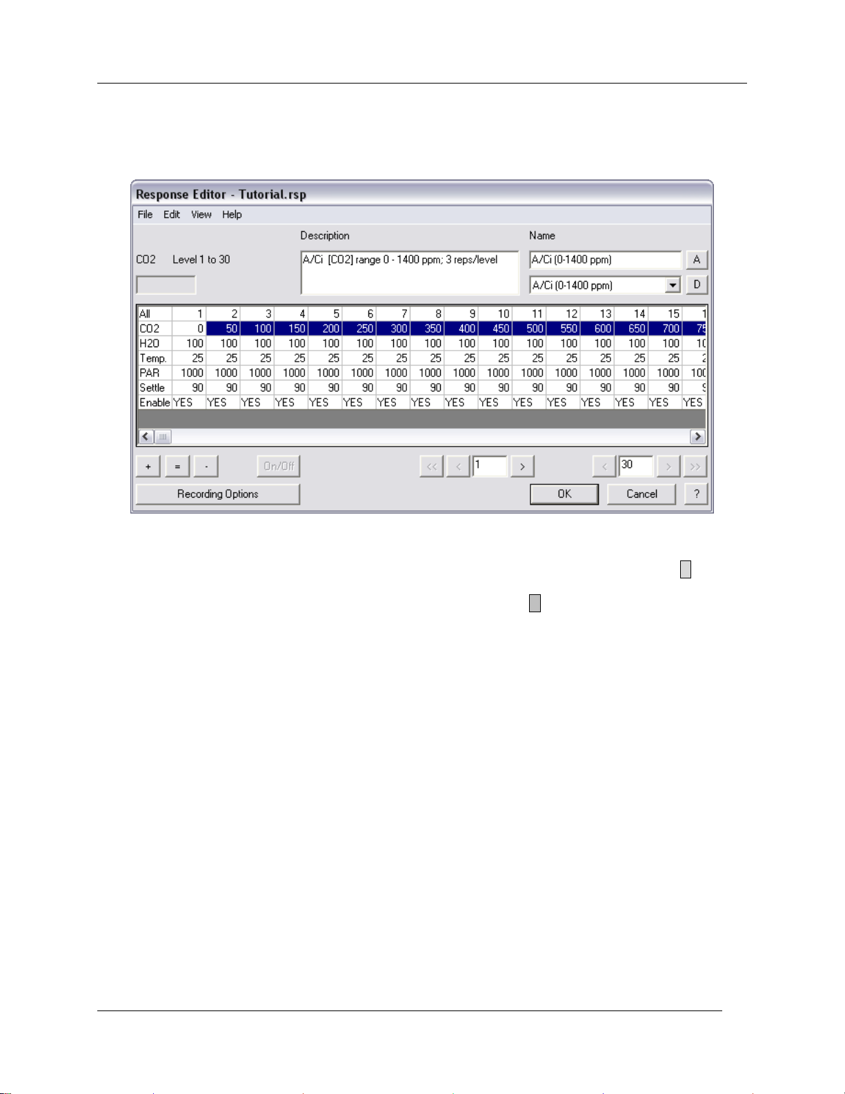
Observing and Recording Leaf Gas Exchange
Select Response Curve to bring up the Response Editor window. Retrieve a previously saved
Response file (.rsp) by clicking File – Open in the Response Editor dialog. To create a new response
curve, enter the desired settings in the Response Editor dialog as shown below:
In the „Name‟ field to the right you may enter a name for your response curve by clicking on Default Rsp
Name 1‟ and typing a new name (optional). You may also enter an optional description. Click A to add a
named Response setup. It is best to save the response file early, and then make alterations to the saved
file. In the Response Editor dialog click File – Save As. Click D to delete the currently selected
response. Each Response File (.rsp extension) can contain up to 10 Response Curves. The options for
each are saved with the Response Curve Definition.
Editing Response Variable Values
Editing All the Values in a Row
In the first column at left are headings for the response curve variables. „All‟ refers to the 30 available
Response Levels in a response curve. Levels 1 through 15 are visible in the Response Editor. If the first
cell marked All is selected, it is possible to reset all the values to the default.
Clicking on the variable heading in the first column will highlight that variable in blue (as CO2, above), and
will bring up the Enter _ Value dialog box. After entering a „Start Value‟, you may increase (Increment),
hold constant (Set Equal), or decrease (Decrement) the „Start Value‟ through your selected range of
Levels. The example above shows a constructed response curve that dynamically increases CO2 only,
experimentally subjecting the leaf to 50 ppm incremental changes
CIRAS-2 Operator's Manual Version 2.04
- 69 -
Page 72
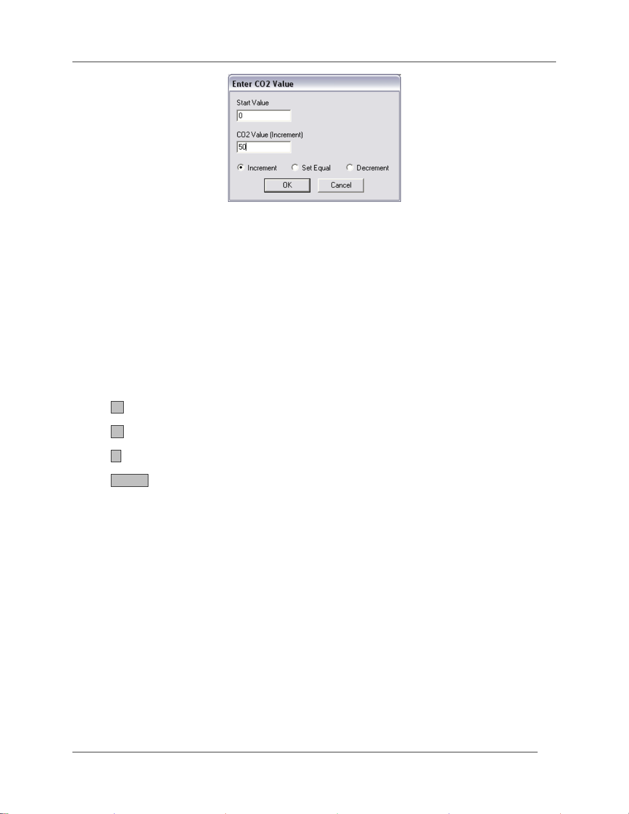
Observing and Recording Leaf Gas Exchange
„Settle‟ refers to the time needed for the leaf to reach a stable (physiological) condition from which reliable
measurements can be recorded, and defines the wait before recording at the next level begins. Level
Settle time is best determined prior to beginning Response Curve recording by pilot testing the
plant/species of interest, using the expected range of CO2 concentration, light intensity, etc. Large interval
changes and delayed or lagging leaf physiological responses must have correspondingly longer „Settle‟
times associated with them. If it is known that a plant responds quickly to changes in light intensity, for
example, the Level Settle time can be decreased. Also, if a change in CO2 concentration is small, then a
shorter level settle time can be set.
It is important to bear in mind that changing CO2 concentrations, etc. may result in time delays of variable
length in order to „propagate‟ through the system. Therefore, it is advisable to test the Response Curve
prior to running an experiment to ensure that adequate Level Settle times are set. The allowable „Settle‟
time range is from 10 to 3600 seconds.
Note that there are 3 buttons in the lower left hand corner of the Response Editor Window:
+ Same as Increment
= Same as Set Equal
- Same as Decrement
On/Off Same as Toggle Enable
Editing Groups of values If several adjacent values from the same row are selected, the Enter _ Value dialog box will appear.
Editing Individual values
To introduce non-incremental values into Response Levels click inside any individual CO2, H2O, Temp.,
PAR or Settle cell. The current parameter, its value and Response Level are displayed in the upper left
field (see below). Enter the new value in the field and click on the cell again to register the value in the cell
for that specific Response Level. Customize additional Response Levels as desired.
CIRAS-2 Operator's Manual Version 2.04
- 70 -
Page 73
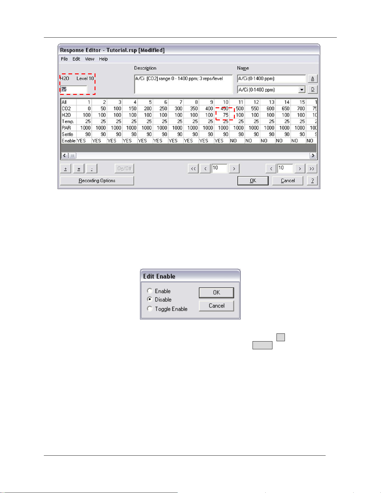
Observing and Recording Leaf Gas Exchange
Enabling Levels
The Enable row can only be modified by a dialog box that appears when a cell in that row (or group of
cells) is selected. Only levels that are enabled will be used in Recording. „Enable‟ refers to the
active/inactive state of the 30 Response Levels. To change the number of active levels in the response
curve click on the cell in the „Enable‟ row where your response curve will end (Level 11 in the example
below). The Edit Enable dialog appears – select „Disable‟. The cell for Level 11 now displays „NO‟
(disabled).
Level 11 now also appears in the lower left field. Repeatedly click the right arrow > button next to the
right field until all remaining levels are highlighted (Levels 11-30), then click On/Off to disable the selected
levels.
CIRAS-2 Operator's Manual Version 2.04
- 71 -
Page 74
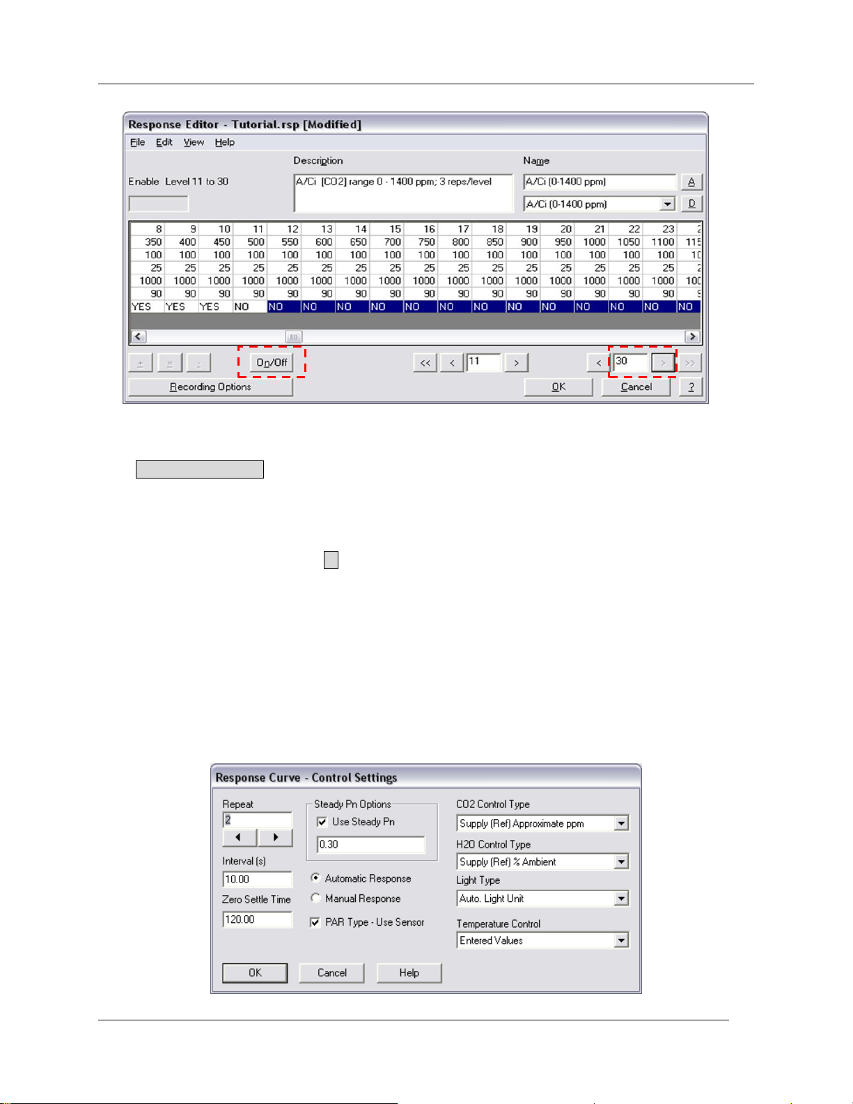
Recording Options
Observing and Recording Leaf Gas Exchange
Click Recording Options to open the Response Curve – Control Settings dialog box. Please note:
the Control Types entered here will be applied only during the Response Curve, and reset to the previous
settings upon completion.
Repeat
Beneath the „Repeat‟ field click the ► button to choose the number of measurements to be recorded at
each level. Later, this will be important for producing means when you process your data.
Interval
The amount of time (seconds) between records.
Zero Settle Time
This applies to the initial settling of the Response Curve measurement and any settle that is caused by a
Zero or Diff Bal that occurs during the Response Curve. Zero Settle Time differs from the Level Settle
Time set in the Response Editor.
CIRAS-2 Operator's Manual Version 2.04
- 72 -
Page 75
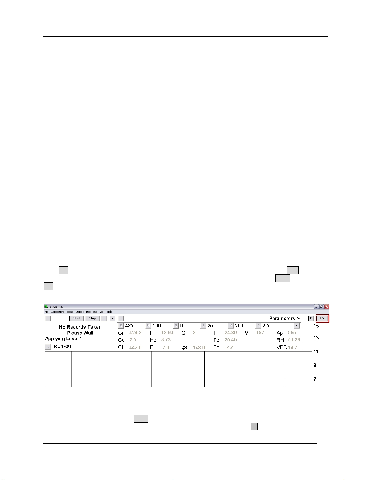
Observing and Recording Leaf Gas Exchange
Steady Pn Options
User-defined. If checked, enter an acceptable range of variability for net photosynthetic rate.
Automatic Response
Response Curve is automatic throughout the course of measurement.
Manual Response
Response Curve is manual throughout the course of measurement. The user must manually record data
and move to the next set level during course of response curve.
PAR Type - Use Sensor
Check this box if the PAR Sensor is to be used to measure and control light in the cuvette. If this box is
not ticked, PAR must be entered manually by the user to be included in measurements.
CO2 Control Type
Both CO2 and H2O Control Types may be changed if desired. For CO2 response curves we recommend
using the „Supply (Ref) Approximate ppm‟ type due to the time delay associated with the precision CO2
control option. Refer to CO2 (0–2000 ppm) on page 51 for more details.
H2O Control Type
Refer to H2O (0-100% or 0 mb-Dewpoint) on page 51 for more details.
Light Type
Defaults to „Auto. Light Unit‟. See Light Type on page 45 for more details.
Temperature Control
Defaults to entered values (25 °C). See Temperature page 53 for more details.
Click OK to accept changes, then in the Response Editor save the Response file. Click Yes to Enter a
file name to save the Response Curve information. After entering a name, click on Save. Again, click
OK when the Select Recording Options dialog reappears. Finally, name and save the data file. After
creating the data file, the response curve measurement will begin.
As in Timed Recording you will be prompted to ‟Press “Start” when steady‟. „RL 1-30‟ indicates that your
Response Curve is currently in the first of 30 selected levels (see image above). Wait until the values are
stable at Level 1, then press the Start button to begin an automatic response curve measurement. You
can review details of your Response Levels at any time by clicking on the … button in the Recording
CIRAS-2 Operator's Manual Version 2.04
- 73 -
Page 76
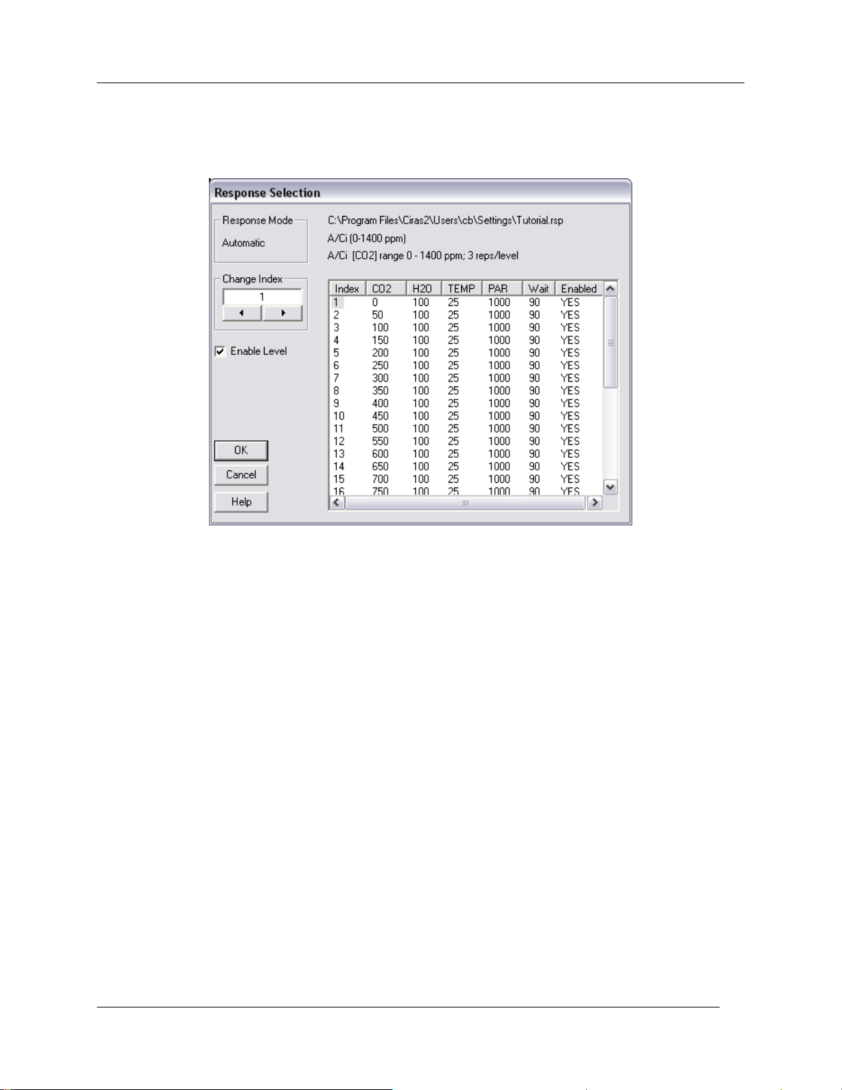
Observing and Recording Leaf Gas Exchange
window (upper left) or from the CIRAS menu bar Recording – Response Level to expand the
Response Selection dialog. Here you can jump to or disable Response Levels – however, you cannot
edit Level values.
On page 75 is an example of what a typical CO2 response curve might look like in the Time Plot: Pn (red)
and Cd (black) increase (in opposite directions) accordingly with upward CO2 concentration changes
(green). Leaf responses stabilized (flattening of each curve) following transitory spikes associated with
CO2 Level changes, with two measurements made after appropriate 90 second „Settle‟ times. The end of
Response Levels are marked by a light green vertical line. In the example, 15 Response Levels have
been completed – note „Settling for Level 16 [1:14 of 1:30m]‟ in upper left of display. The corresponding
Data Plot view of the A/Ci curve is also shown.
Please note: CIRAS-2 firmware is programmed to perform a Diff Bal whenever CO2 concentration
changes exceed 100 ppm or H2O partial pressure exceeds 3 mb. Differential Balancing during a
Response Curve will automatically suspend the Response Level, requiring a short leaf reacclimation
period. This will be the case if you selected „Automatic‟ in the Zero/Diff Bal Mode option. To avoid this
you can store a set of values corresponding to your experimental range of CO2 and H2O, and then select
„Auto Zero with Stored Diff Bal‟ in the Zero/Diff Bal Mode option (see Stored Diff Bal on page 78).
CIRAS-2 Operator's Manual Version 2.04
- 74 -
Page 77
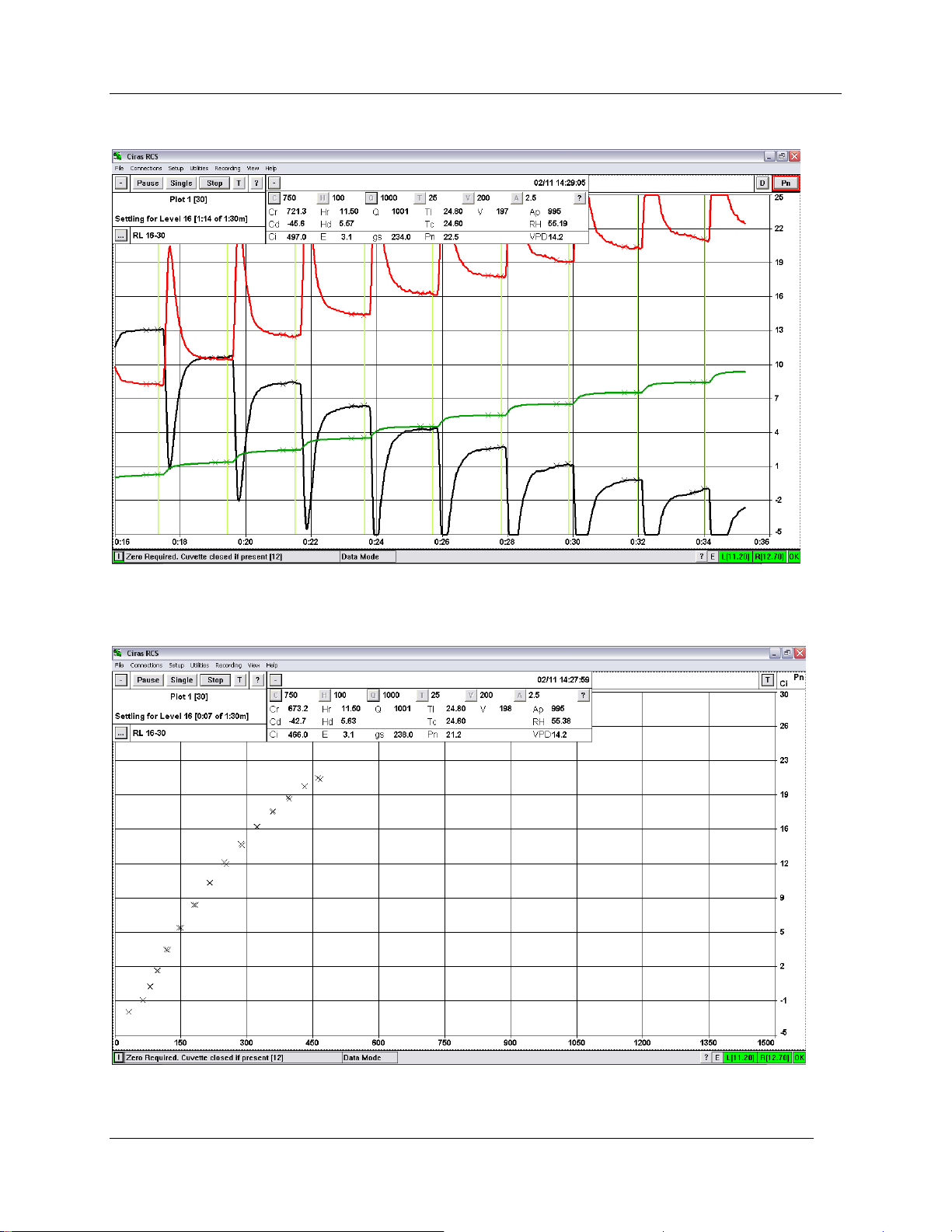
Time Plot
Observing and Recording Leaf Gas Exchange
Data Plot
CIRAS-2 Operator's Manual Version 2.04
- 75 -
Page 78
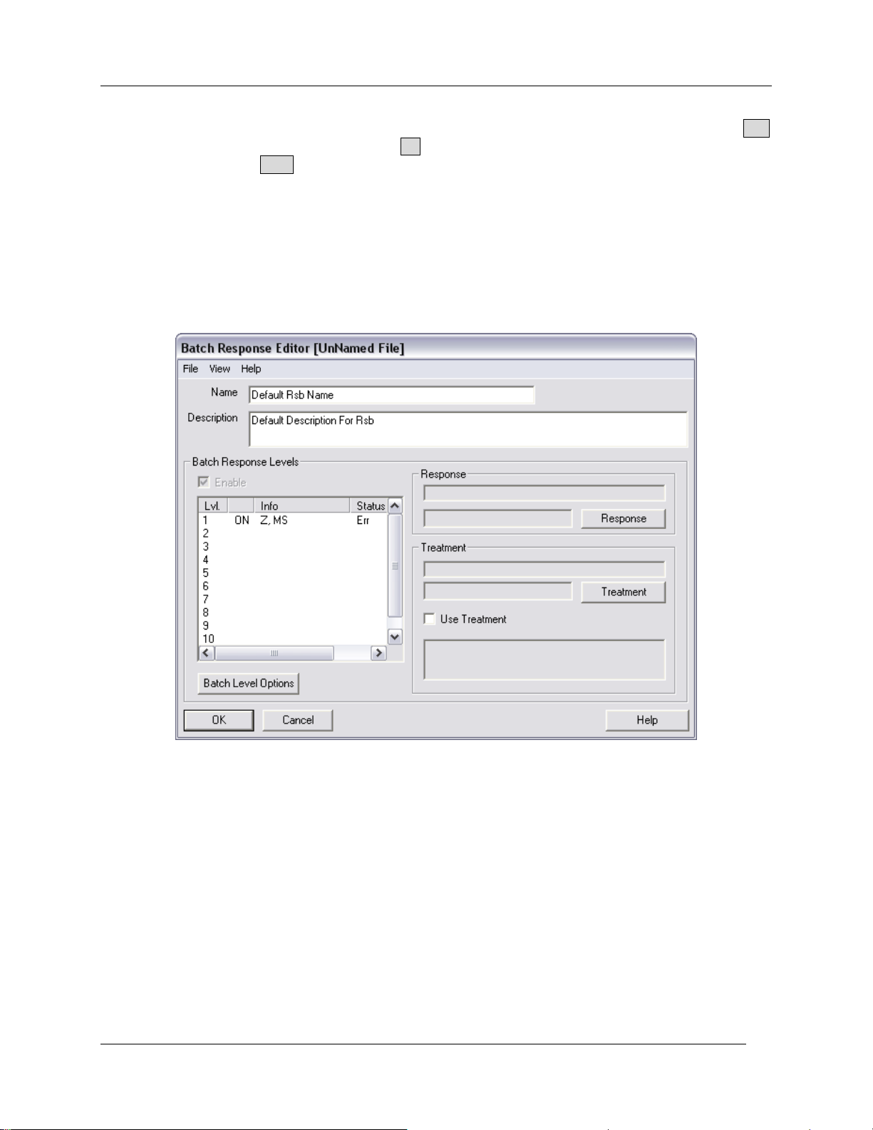
Observing and Recording Leaf Gas Exchange
At the conclusion of the response curve, you will be given the option to either restart or end the
measurement. Use this opportunity to place a different leaf/plant in the leaf chamber if desired - click Yes
to repeat the identical response curve or No to end the recording session. To terminate the
measurement, press the Stop button.
Batch Response Curves
Batch Response Curves are designed to allow multiple Response Curves to be run consecutively. Ten
Batch Response Levels are definable within a Batch Response Curve. Instructions for setting up, storing
and running Batch Response Curves is very similar to those described in the section Response Curve
starting on page 68.
Enable Batch Response Levels
Click on a Batch Response Level number under „Lvl.‟ To highlight, then check the „Enable‟ box.
Batch Level Options
Show Prompt
If checked, at the beginning of the Response Curve, the defined prompt is displayed. If enabled the user
must respond to the prompt before the level continues
Force Zero and Automatic Settle
At the beginning of a Response Curve, these options control whether the Software forces a Zero and
whether the user should indicate that the system is stable. Please note: For Batch Response Level 1, a
Zero is always forced, and the user must indicate that the system is stable.
CIRAS-2 Operator's Manual Version 2.04
- 76 -
Page 79
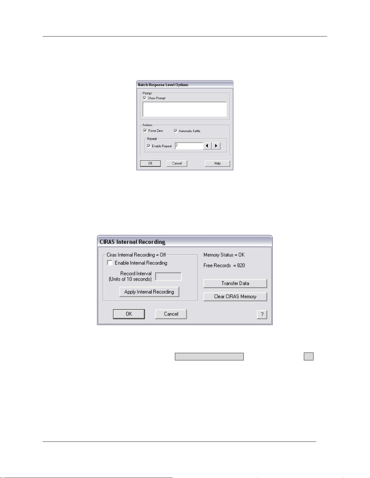
Observing and Recording Leaf Gas Exchange
Repeat
If „Enable Repeat‟ is checked, the software will repeat the Response Curve for the defined number of
repeats from 2 to 10 times. If unchecked, the Response Level only runs once.
CIRAS Internal Recording
If required, data can be saved directly onto CIRAS-2 memory. From the menu bar select Utilities CIRAS Recording to record measurements internally to CIRAS-2. The maximum number of records that
can be stored internally is 820. The following dialog box will appear:
Click on the “Enable Internal Recording” box and enter the value required in the “Record Interval” box.
Please note: The value you enter will be that value x 10. In other words, if you want to record every 60
seconds, enter 6 in this box and click on the Apply Internal Recording button. Then, click OK and
readings will be taken automatically at the recording interval that was set. To terminate CIRAS-2 Internal
Recording, return to Utilities - CIRAS Recording and click on “Enable Internal Recording” to disable it.
Please note the following: Unlike normal recording (i.e. Keypress, Timed Recording, etc.) where record
marks are displayed to show when a measurement is being recorded, you will not see any marks or ticks
on the display when readings are taken.
CIRAS-2 Operator's Manual Version 2.04
- 77 -
Page 80

Observing and Recording Leaf Gas Exchange
Enable Internal Recording
If selected, CIRAS-2 will store records internally. Maximum number of records stored internally = 820
records.
Record Interval
Units are based on 10 second increments. If set to 1, the recording interval is 10 seconds. If set to 2,
recording interval is 20 seconds, etc.
Apply Internal Recording
Updates CIRAS-2 with the new information.
Transfer Data
To transfer internally stored CIRAS-2 data to your PC, click on the Transfer Data button. Available
records are transferred from CIRAS-2 into the selected file (dmp extension). Please note: „Enable
Internal Recording‟ must not be selected prior to transfering data. The Save Ciras Internal Records
as… dialog will be displayed prompting you to enter the name of the file where the data will be stored.
After naming the file, click the Save button. At the conclusion of internal data transfer, a message will
confirm that Data Dump is complete and the number of records transferred.
Click OK when finished. The data will normally be saved to the following location on the PC unless
otherwise specified:
Program Files\Ciras2\Users\PPSystems\DataFiles\
Clear CIRAS Memory
To clear internally stored CIRAS-2 records, click the Clear CIRAS Memory button. After clearing the
memory, the following will be displayed:
Memory Status = OK
Free Records = 820
Stored Diff Bal
The Reference and Analysis analyzers in CIRAS-2 are absolute analyzers and the displayed differentials
derive from the difference between them. In manufacture and calibration, every effort is made to match
the analyzers as closely as possible, but even so differences still exist. Therefore, for accurate results, the
differences must be known. To determine the difference, the Reference air is passed through both
analyzers and the offset is recorded for application to future measurements. We call this process
“Differential Balancing”, or Diff Bal.
Since this process takes some time it may interrupt response curve measurements. It is possible to
determine the offsets over the working concentration range before measurements begin. Six pairs of
concentrations are required, but to simplify the process you only need to enter maxima and minima. Both
CO2 and H2O must be entered and the ranges MUST cover the expected measured values.
CIRAS-2 Operator's Manual Version 2.04
- 78 -
Page 81
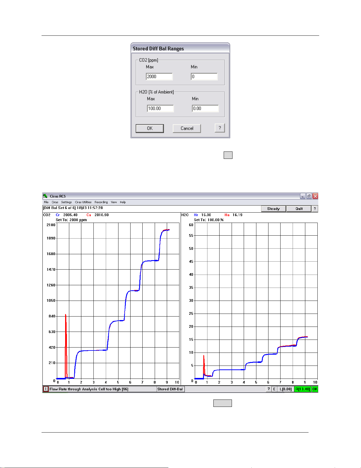
Observing and Recording Leaf Gas Exchange
Go to Utilities – Stored Diff Bal. Enter the range of values and click OK.
The cuvette must be fully connected, though it does not have to be closed and a CO2 cartridge must be
present. The measurement screen will then be displayed and initially CIRAS-2 will zero. CIRAS-2 will
then be set to the first set of values.
When the graph shows that the readings have stabilized click on Steady. CIRAS-2 will now do a Diff Bal
and on completion, set to the next pair of values. The process should repeat 5 more times. On
completion of the sixth pair, quadratic equations are fitted to the measured Reference concentrations and
CIRAS-2 Operator's Manual Version 2.04
- 79 -
Page 82
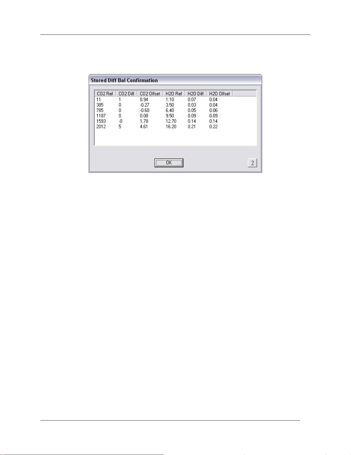
Observing and Recording Leaf Gas Exchange
offsets. The results are displayed showing the measured values and offsets, and the calculated offsets.
You then have the option of accepting or rejecting the offsets. If accepted, CIRAS-2 will use the
calculated values as long as the reference concentrations are within the set up range.
CIRAS-2 Operator's Manual Version 2.04
- 80 -
Page 83
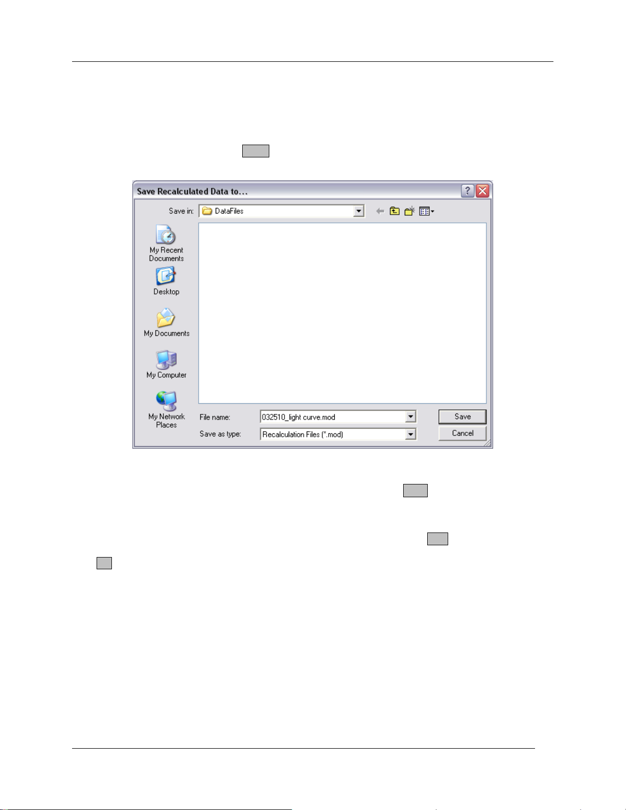
Recalculate Data
Recalculate Data
There may be situations when you need to recalculate your data, such as post-determination of actual leaf
area, incorrect entry of PAR value, etc. To recalculate data click on File - Open and select the data file
that you want to recalculate and click Open.
The Save Recalculated Data to… dialog will appear. The selected file will be automatically given a .mod
extension. The original file (.dat extension) will remain unaltered. Click Save to continue. The CIRAS-2
Photosynthesis Recalculation dialog will appear. Initially, data from the first record stored is displayed.
To recalculate the data for the displayed record, check off the parameter(s) needing to be changed under
„Recalculation Values‟ and enter the desired value(s). Alternatively, click on Skip to move to the record
requiring recalculation and make the desired changes. After completing changes for a specific record,
click OK to accept the changes and to have the data recalculated.
CIRAS-2 Operator's Manual Version 2.04
- 81 -
Page 84
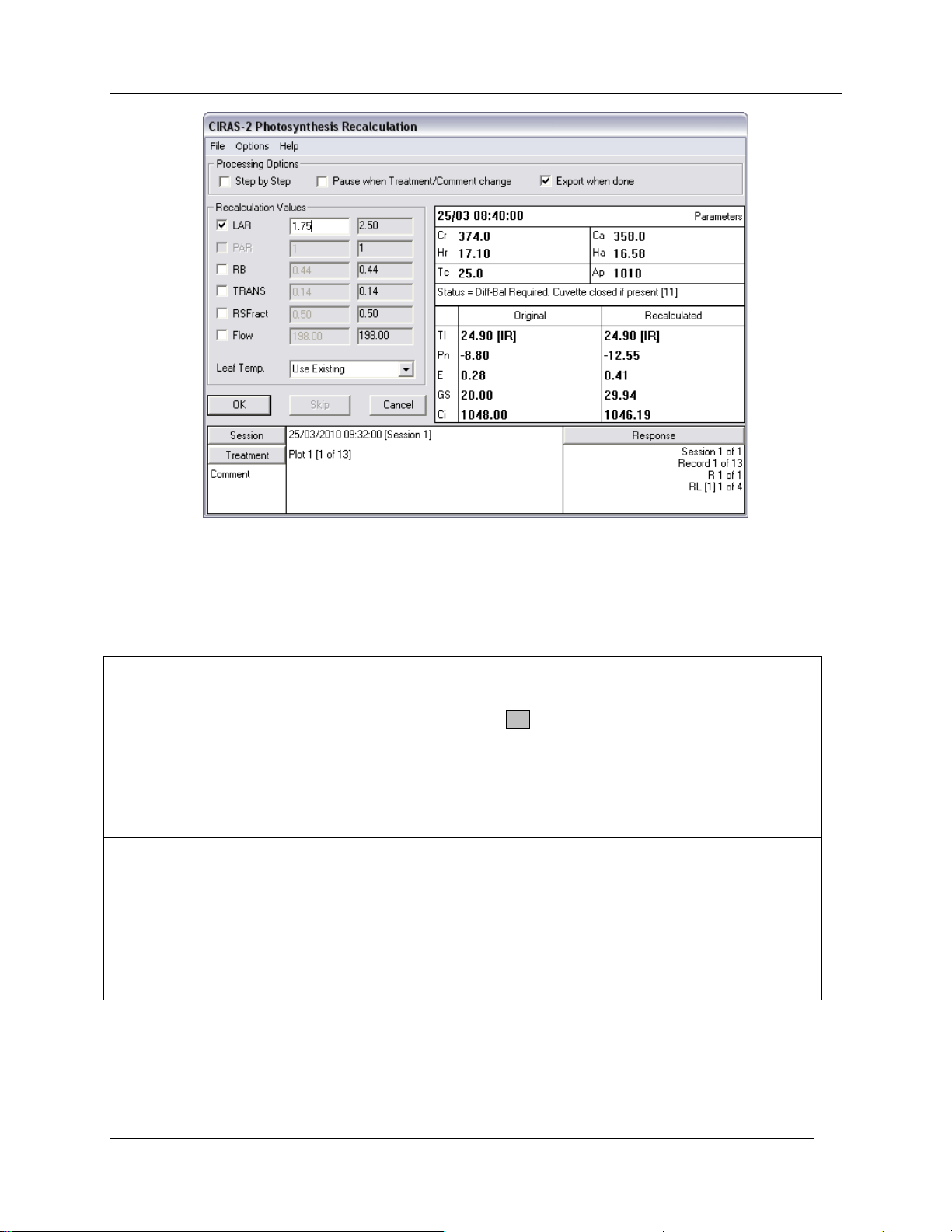
Recalculate Data
Step by Step
If selected, each line of data is recalculated and the
results displayed. Changes in recalculation values
are displayed automatically. After making changes,
pressing OK will write the new values and proceed to
the next data line.
If not selected, data is calculated and the next line
read automatically. However, the software will pause
depending if Pause when Treatment/Comment
Changes (See below) is selected.
Pause when Treatment/Comment change
Regardless of the Step by Step option selected, if
this is ticked, it will cause the software to pause to
allow a re-assessment of the recalculation options.
Export when done
If selected, the Export Dialog is loaded automatically
upon completion of the recalculations for the file.
See Export Data on page 88. If not selected, the
recalculation file will be loaded according to the
options set for viewing files available from the
Options, Edit menu.
Processing Options
There are 3 processing options available:
CIRAS-2 Operator's Manual Version 2.04
- 82 -
Page 85
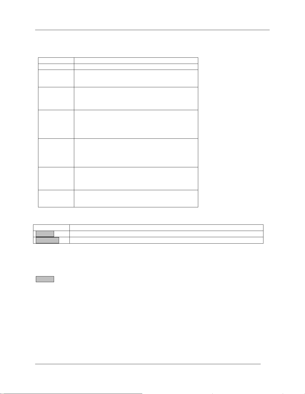
Recalculation Values
Parameter
Description
LAR
Leaf Area.
PAR
PAR. This is typically ghosted out and should only be
available when using our “Manual” style cuvettes and
PAR was manually entered and not measured.
RB
Boundary Layer resistance of Cuvette. The value
depends upon the type of cuvette supplied. The
factory default value can be found on the cuvette
handle or packing list supplied with the system.
TRANS
The transmission characteristics of the cuvette
window. This value is different for each type of
cuvette and is automatically set by the CIRAS-2 by
default when selected in the Parameters Editor dialog.
This value should not require changing.
RSFract
The ratio of stomata on the upper and lower surface
of the leaf. Please note that the ratio is in terms of
the upper leaf. During recalculation, the value should
be entered as a percentage of 1 (i.e. 50% Stomata on
top surface should be entered as 0.50).
Flow
Flow rate of the integral air supply. If the CIRAS-2 air
supply is used, there should be no need to change
this value. If an external air supply is used, this value
may require changing.
Leaf Temp.
Leaf Temperature. If set to Energy Balance, leaf
temperature is automatically recalculated. If set to
Use Existing, recalculation does not occur.
Click On:
To:
Session
Review information relating to the CIRAS-2, data, graphics, etc. .
Treatment
Review any information/comments associated with a particular record (treatment).
Recalculate Data
Information
There are 5 tabs (windows) associated with the Information window. To get to this window, click on the
Session button when the CIRAS-2 Photosynthesis Recalculation dialog is open:
CIRAS-2 Operator's Manual Version 2.04
- 83 -
Page 86
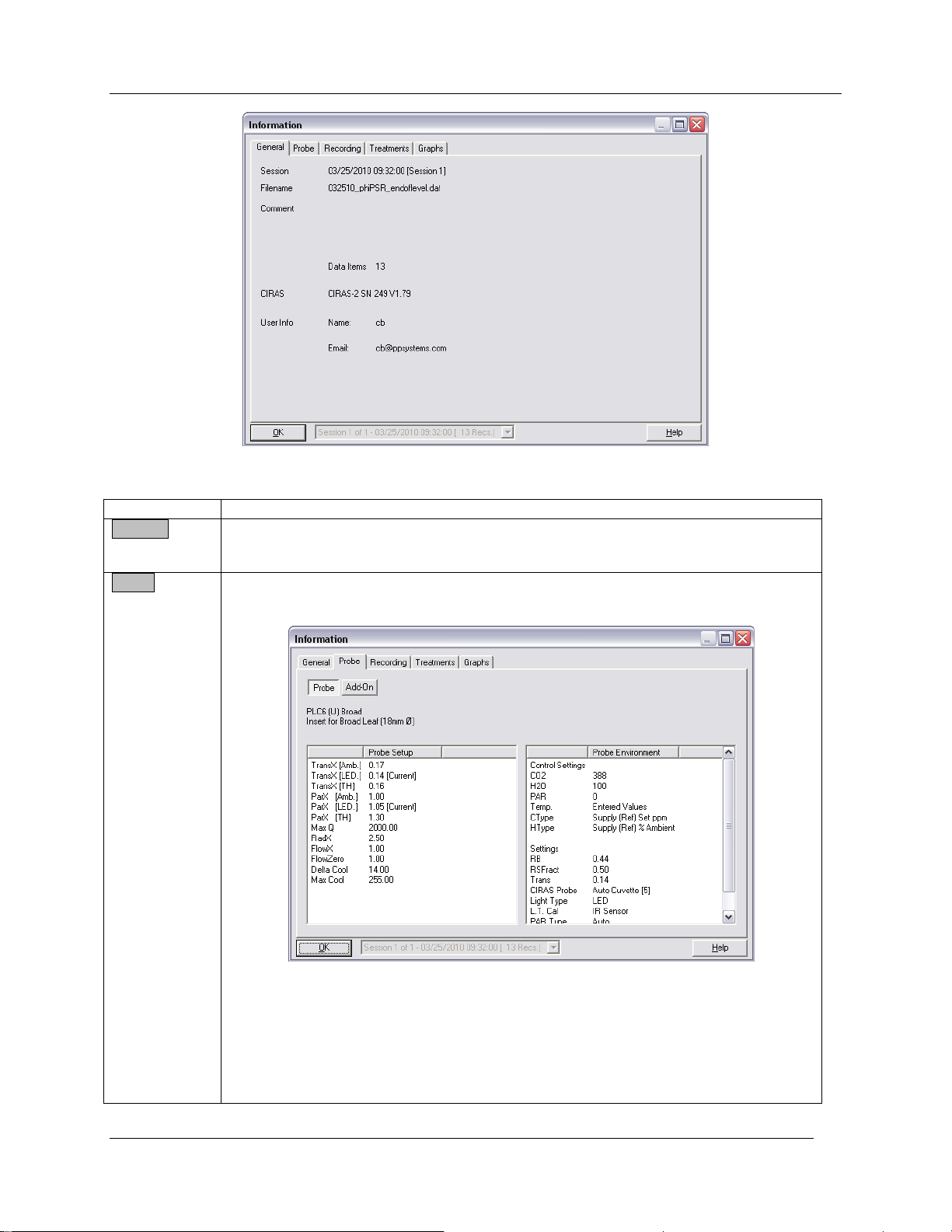
Recalculate Data
Click on:
To:
General
View session date and time, file name and information related to the CIRAS-2 and
user information. The General tab will open first when Session is selected as
described above.
Probe
To view information related to A/D reads associated with the type of probe (i.e. leaf
cuvette) used, system setup, etc.
CIRAS-2 Operator's Manual Version 2.04
- 84 -
Page 87
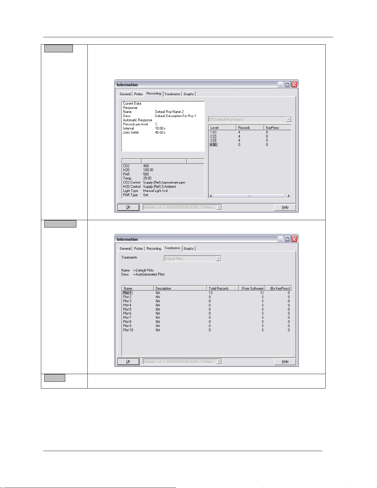
Recalculate Data
Recording
View the recording type selected (i.e. keypress, timed, response curve) and
associated settings.
Treatments
To view treatment descriptions as they pertain to different plots/records.
Graphs
View measured/stored data graphically.
CIRAS-2 Operator's Manual Version 2.04
- 85 -
Page 88
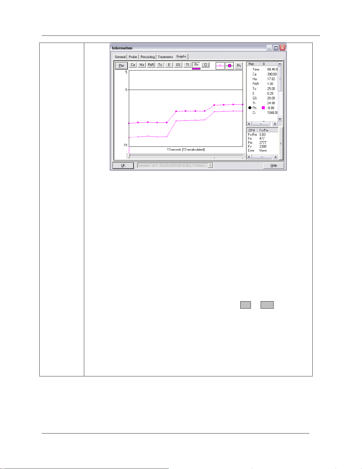
Recalculate Data
Up to 8 measured/calculated parameters can be displayed at one time. These
parameters include:
Ca Analysis CO2 (ppm)
Ha Analysis H2O (ppm)
PAR PAR (µmol m-2 s-1)
Tc Chamber Temperature (°C)
E Evaporation (Transpiration) Rate (mmol m2 s-1)
GS Stomatal Conductance (mmol m2 s-1)
Tl Leaf Temperature (°C)
Pn Photosynthesis (Assimilation) Rate (µmol m2 s-1)
Ci Internal CO2 Concentration (ppm)
To view one of the above parameters, click on the desired button. A colored bar will
be displayed below your selection identifying the parameter. Each parameter can be
toggled on or off by clicking it. Data ranges (Maximum and Miniumum) are
calculated by the software.
To switch between Data and Plot view type, click on the Plot or Data button in the
upper left hand corner. In Data View, the X-Axis is based on the number of records
encountered in a session, not on time. If exporting data, the legend for the “current”
value is displayed as a solid dot. The recalculated values (if any), are displayed as
'hollow' dots.
In Plot view, only two values can be plotted against each other. If recalculated data is
present, the recalculated values are drawn as red circles with green halos. Original
data are drawn as black circles with red halos. The field to the right in Plot and Data
views lists the original and recalculated variables, and their X- and Y-axis positions
are indicated by arrow symbols.
CIRAS-2 Operator's Manual Version 2.04
- 86 -
Page 89
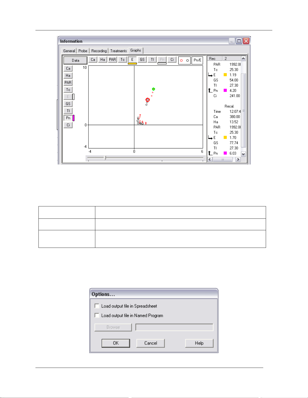
Recalculate Data
Recalculation
Options
Stores the parameters to recalculate and how the file is processed.
Export Options
Stores the fields and what additional data to export. Export options for
data, dumped data and closed system data are treated individually.
Shared Options
Stores fields from the data file are displayed in the 'preview' graph. Which,
if any, actions to perform after the Export/Recalculation are performed (i.e.
Load the output file into a spreadsheet program).
Options
With the CIRAS-2 Photosynthesis Recalculation window open, select Options. Options files contain
stored options for Recalculation and Export of Data Files. Each Options file is divided into 3 sections for
the storage of:
Options files are stored by default in the user's directory. Unlike settings files etc, only one set of options
are maintained per file.
Select Options - Edit Options to select the desired method of having recalculated or exported data
opened by another program (i.e. Excel, Notepad, etc.).
CIRAS-2 Operator's Manual Version 2.04
- 87 -
Page 90
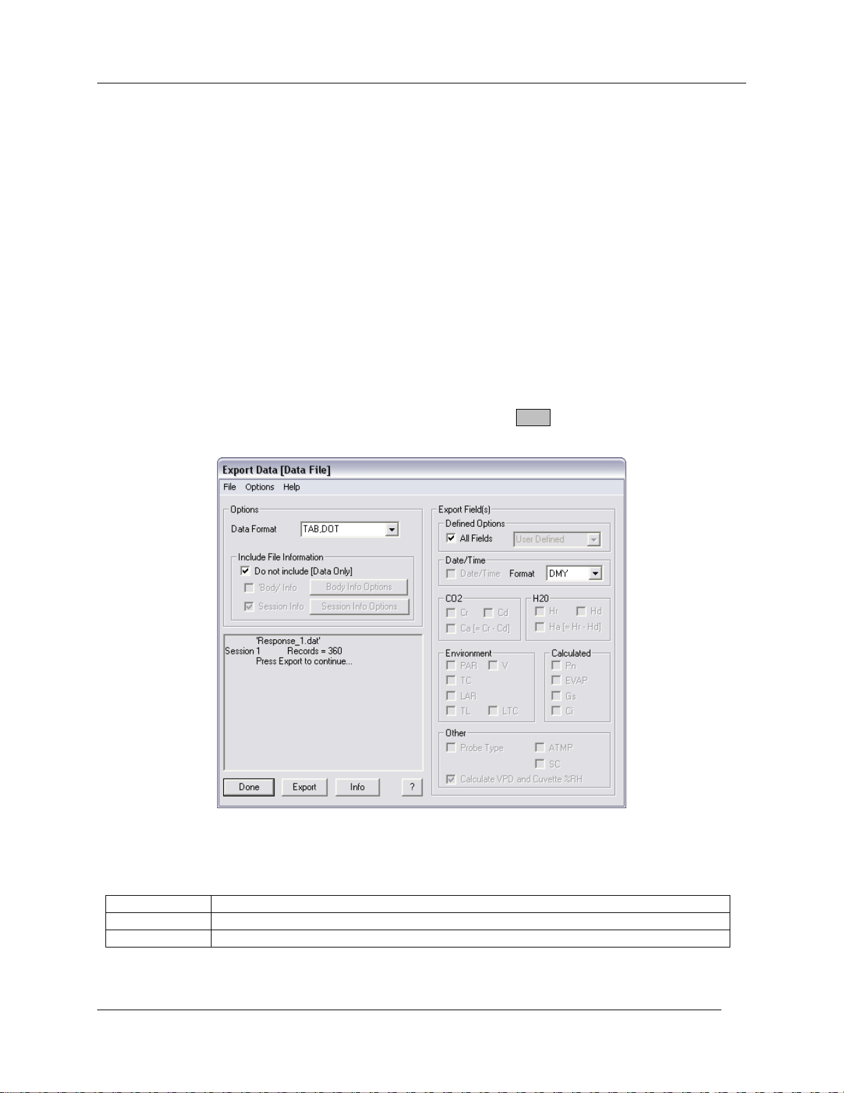
Recalculate Data
TAB,DOT
Data is exported using tab deliminator and '.' as decimal separator.
CSV,DOT
Data is exported using comma deliminator and '.' as decimal separator.
TAB,COMM A
Data is exported using tab deliminator and ',' as decimal separator.
Load output File in Spreadsheet
This option relies on file types being associated with certain programs. Check „Load output file in
Spreadsheet‟ if you want all processed data files to automatically open in the appropriate program based
on the file extension. For example, if files with .dat extensions are associated with Excel, the file will
automatically be opened in Excel.
Load output File in Named Program
Use the 'Browse' button to locate the SpreadSheet (or other) program that you would like to use. Tick off
“Load output file in Named Program” to have all processed data files open up automatically in the program
selected.
Please note: Please contact PP Systems (see Contact Information on page 11) if the above options do
not work properly on the UI.
Export Data
This feature allows you to export all stored CIRAS-2 Data Files into a user specified and simplified format
for use in spreadsheet applications such as Microsoft Excel. Click on File - Export Data and select the
data file (.dat extension) that you would like to export, then select Open. The Export Data (Data File)
Window appears as below:
Options
Data can be output in 3 formats:
The deliminator selected defines the extension of the files selected for export (i.e. .tab or .csv).
CIRAS-2 Operator's Manual Version 2.04
- 88 -
Page 91
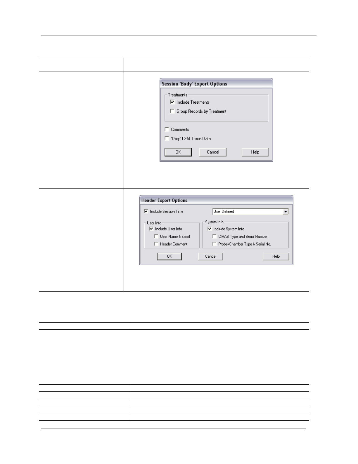
Include File Information
Do not include (Data Only)
If ticked, only the data will be exported per the users selection without
any “Body” or “Session” information.
„Body‟ Info
Exported data can include treatment information along with any
comments associated with records. You can also group records by
treatment.
Session Info
Exported data can include Session Time, user information (email
address) and system information (i.e. CIRAS type, serial number of
instrument, probe type, etc.
Check:
To:
All Fields
Export all fields (i.e. measured and calculated data). In addition,
you can select the Date/Time format that you prefer. You have the
option of selecting:
None : Day, month, year and time are output as separate
fields
DMY: Day/Month/Year is output in a single field.
MDY: Month/Day/Year is output in a single field.
Pn/Ci only
Export Photosynthesis (Pn) and Ci only.
Ca and Ha
Export analysis CO2 (Ca) and H2O (Ha).
All CO2 and H2O
Export all CO2 and H2O related data.
Calculated
Export all calculated parameters (Pn, Evap, Gs, Ci)
Recalculate Data
Export Fields
There are numerous fields of data that can be output to suit your needs.
CIRAS-2 Operator's Manual Version 2.04
- 89 -
Page 92

Recalculate Data
Environment
Export all environmental parameters (PAR, TC, LAR, TL, V,).
Please note:, LTC is not included with this selection.
Drop Flag Fields
Export user selected fields. If selected, tick off the fields that you
would like to export.
Important: To recover VPD and RH data recorded during a live session you must first deselect „All Fields‟
and select „Calculate VPD and Cuvette %RH‟. Then check „All Fields‟ again.
After selecting the appropriate fields to be exported, click on Export . You will be prompted to save the file
(.tab extension) in the format selected under Options (above). After naming the file, click Save.
Exportable file types are CIRAS-2 Recorded Data (.dat), CIRAS-2 Internal Records (.dmp) and Closed
System Measurements (.csc). Recalculation Data (.mod) is treated as CIRAS-2 Recorded Data.
Options
Refer to the section above on page 82.
CIRAS-2 Operator's Manual Version 2.04
- 90 -
Page 93

Transferring Data From CIRAS-2 to Your Computer
Transferring Data From CIRAS-2 to Your Computer
On the Integral PC (Pencentra), all data files are stored in the following directory:
\Storage Card \ Users \ UserName \DataFiles
On the PP Systems‟ User Interface (UI), all data files are stored in the following directory:
\FlashFX Disk\Users\UserName \DataFiles
On an External PC, all data files are stored in following directory:
C:\Program Files\Ciras2 \Users\UserName\DataFiles
Each user folder contains the following :
Data Files Folder Photosynthesis and CFM Data (.dat)
Soil Respiration and Whole Canopy Data (.csc)
Diagnostics (.txt)
Extended Diagnostics (.dia)
Settings Folder Settings Files (.set)
Parameters (.prm)
Response Curve Definitions (.rsp)
Treatments (.trt)
CFM Options (.cfm)
To view stored data files in a spreadsheet program such as Excel, you must first transfer stored records
from the integral PC (Pencentra) or User Interface (UI) over to your desktop PC. To do this, you can use
ActiveSync, the RS232 Null Modem, or by moving them from the UI to a Flash Card via the PCMCIA drive.
Records can be viewed with Notepad on the UI if required.
PCMCIA Card
This is the simplest method of data transfer, requiring no cables or third-party software.
1. Remove the plastic cover from the PCMCIA card slot and insert your CompactFlash Adaptor and
card.
2. Open Windows Explorer on your UI and navigate to the FlashFX Disk folder to identify the files to be
transferred to the flash card. To access Window Explorer you can either i) double-click the My
Computer icon on the Desktop or ii) from the Windows Taskbar click Start – Programs – Windows
Explorer. Normally, .dat files are stored in the \FlashFX Disk\Users\User Name \DataFiles
subdirectory.
3. Copy and paste the files to the Storage Card (flash card) folder icon, then move the flash card to your
desktop PC.
RS232 (Null Modem) Connection
Establishing An ActiveSync Connection For Data Transfer from UI To PC
1. Turn off the CIRAS-2 (with no Null Modem cable connected).
CIRAS-2 Operator's Manual Version 2.04
- 91 -
Page 94
Transferring Data From CIRAS-2 to Your Computer
2. On your PC, start ActiveSync (Must be ActiveSync version 3.7.1 or later). At this stage, it should
show that you are not connected. With the ActiveSync window opened, go to File, Connection Settings
and select the COM port (normally COM1) to be used on your PC. Click Ok.
3. Turn the CIRAS-2 on and wait for it to get to the opening Log-in screen. Next, exit from the CIRAS-2
Remote Control Software by clicking on Quit.
4. Connect Null Modem cable between the 9 pin RS232 plug on the User Interface and the COM port on
your PC Computer.
5. From the Windows CE desktop on the UI, click on Start icon on lower left hand corner of the display,
Programs, Communication, ActiveSync.
At this stage, you should have a successful connection (partnership) between the User Interface and your
desktop PC. If prompted to “Setup A New Partnership”, click No and then Next. The Microsoft
ActiveSync window should show that you are connected as a guest. If you do not connect, perform the
following checks:
On your desktop PC
Open ActiveSync and make sure that you are running version 3.7.1 or later.
Click on File, Connection Settings and make sure that “Allow serial cable or infrared connection to
this COM port” is ticked off.
On the User Interface
Click on the Start icon on the lower left hand corner of the display, Settings and Control Panel.
Next, double-click on “PC Connection” and ensure the following:
A. Make sure that “Enable direct connections to the desktop computer” is ticked off.
B. Make sure that “19200@com1” is shown under “When enabled, connect to the desktop
computer using:” If it is not, click on Change Connection… and change it to 19200@com1.
To transfer stored files from the UI to PC, open Windows Explorer on your PC and navigate to Mobile
Device\FlashFX Disk folder and identify the files to be transferred to the desktop PC. Normally, the files
are stored in the \FlashFX Disk\Users\User Name \DataFiles subdirectory. Simply copy and paste the
files to the desired folder on your desktop PC.
ActiveSync® Communications Software
Microsoft ActiveSync is a program to allow communication between the User Interface (or integral PCPencentra) and your PC. It is commonly used to transfer stored CIRAS-2 data files from the UI (or
integral PC-Pencentra) to your PC. Making a serial connection with ActiveSync is fairly straightforward.
This program must be loaded on your PC before transfer of stored CIRAS-2 data files can take
place.
You must visit the Microsoft website to obtain the latest version of ActiveSync. As of the printing of this
manual, the website address is located at:
http://www.microsoft.com/windowsmobile/downloads/default.mspx
Microsoft regularly changes the layout of their website, so it may be necessary to search for the current
location.
It is important to note that for proper operation, you must ensure that you are running ActiveSync
version 3.7.1 or later.
CIRAS-2 Operator's Manual Version 2.04
- 92 -
Page 95
Transferring Data From CIRAS-2 to Your Computer
For Customers That Are Using The Integral PC (Pencentra)
The Integral PC (Pencentra) is supplied with ActiveSync® software for communication between PCs. It is
preinstalled on the Integral PC (Pencentra). The user must install it on their own PC. There is an early
version supplied on CD ROM (Microsoft Windows CE Services) with the Integral PC (Pencentra), but we
recommend that the latest version is downloaded from the Microsoft® website described above.
Carefully follow the installation instructions. Try and ensure there will be no conflict over the COM port
chosen because ActiveSync® will retain control of the port by default. If the intention is to also run the
Remote Control Software on the external PC, then use a different COM port if possible. If there is conflict,
it must be disabled when not in use (File, Connection Settings, Dis-allow serial cable connection to this
COM port).
An RS232 “Null Modem” Data Communications cable has been provided with all systems supplied with
the integral PC (Pencentra). The integral PC (Pencentra) must be disconnected from the CIRAS-2
analyzer and connected to the other PC instead. Connect to the designated COM port on the other PC.
The two PCs will automatically establish communication. Once connected, you can easily transfer files
from the integral PC- Pencentra to your PC. To transfer stored files, open Windows Explorer on your PC
and navigate to Mobile Device on your PC and locate the subdirectory where the data files are stored on
the integral PC-Pencentra. Simply copy and paste the files to the desired folder on your PC.
If there are problems, check the following:
Check the COM port used.
Check all the plugs are correctly inserted.
Check there is no other task controlling the PC COM port
For Customers That Are Using Our User Interface (UI)
For all CIRAS-2 customers that have our UI, we‟ve supplied both an RS232 “Null Modem” Data
Communications cable and USB cable. This way, we cover both older PC‟s that have older serial
connections and later PC‟s that feature USB ports. By default, the UI expects that the ActiveSync
communications link to be the USB port. Therefore, if using the USB cable, you MUST ensure that you
have loaded the appropriate USB drivers to your PC. These drivers allow you to connect the USB client
port of the UI to your PC to create and ActiveSync connection.
USB Connection
Installation of USB Drivers On Your PC
1. Ensure that both the CIRAS-2 and PC are both on.
2. Next, connect the USB client port of your UI (see the User Interface (UI) Operator‟s Manual if required
to locate the USB port) to your PC using the USB cable (Type A Male to Type B Male). Your PC will
likely report the following messages:
Found new hardware ….
USB device …
It should then run the Found New Hardware Wizard (It may take a minute or so for the Wizard to come up
on your PC).
CIRAS-2 Operator's Manual Version 2.04
- 93 -
Page 96
Transferring Data From CIRAS-2 to Your Computer
6. Insert the CD supplied by PP Systems which contains the required USB driver files.
7. Tick off “Install the software automatically (Recommended)”.
8. Click Next.
9. If not detected automatically, click on “Browse” and locate the WCEUSBSH.SYS file on the CD ROM
supplied by PP Systems.
10. Click on WCEUSBSH.SYS and Open then Ok. A “Hardware Installation” warning may appear. If so,
click “Continue Anyway”.
11. If successful, you should get a message indicating complete installation.
12. Click Finish.
The USB drivers should now be installed properly on your PC. Once completed, you should not have to
step through this process again unless using a different PC with your CIRAS-2.
Establishing An ActiveSync Connection For Data Transfer from UI To PC
1. Turn off the CIRAS-2 and disconnect the USB cable from the UI.
2. On your PC, start ActiveSync (Must be ActiveSync version 3.7.1 or later). At this stage, it should
show that you are not connected.
3. Turn the CIRAS-2 on and wait for it to get to the opening screen.
4. Connect the USB cable between your UI and your PC.
5. You should now be connected. When asked to “Set up a new partnership”, click No and then Next.
To transfer stored files from the UI to PC, open Windows Explorer and navigate to Mobile Device\FlashFX
Disk folder and identify the files to be transferred to the PC. Simply copy and paste the files to the desired
folder on your PC.
If there are problems, check the following:
Check the COM port used.
Check all the plugs are correctly inserted.
Check there is no other task controlling the PC COM port
CIRAS-2 Operator's Manual Version 2.04
- 94 -
Page 97
Shutting Down the CIRAS-2 System
Shutting Down the CIRAS-2 System
The following order of events is important to ensure an orderly shutdown once measurements are
completed:
Exit the CIRAS-2 Remote Control Program by selecting File – Exit in the CIRAS-2 menu bar.
Power off CIRAS-2 by pressing the red On/Off switch.
Disconnect the cuvette from the external 12V DC power supply (if connected).
Clean the cuvette head and leave open to avoid compressing the gaskets when not in use.
Remove the leaf cuvette electrical connector (PLC) from CIRAS-2 by pulling back on the sleeve
around the front of the connector, not the body of the connector or the wire.
Remove the reference (R) and analysis (A) gas connectors from CIRAS-2 by pulling back on the
sleeve around the front of the connector, not the body of the connector or tubing.
Remove the entire CO2 regulator assembly from inside the CIRAS-2 console and keep separate if
CIRAS-2 is to be stored in a confined space or container, such as the carrying bag. CO2 from the
cartridge is constantly diffusing, whether or not the regulator assembly is installed in CIRAS-2. If
left in a confined space, CO2 from the cartridge will build up in the absorber columns, causing
premature exhaustion of the chemicals and slower instrument warm-up as excess CO2 is flushed
out the next day.
If necessary remove both 12V NiMH batteries and place them on their own chargers (supplied by
PP Systems).
CIRAS-2 Operator's Manual Version 2.04
- 95 -
Page 98
Measuring Chlorophyll Fluorescence with the CFM
Firmware (EPROM)
Version 1.77 or greater
To check this with your system, run the
CIRAS-2 software and click on View -
Quick Info. This is shown under
“Hardware Information” at the top of the
window next to the serial number of your
instrument.
Software
Version 1.06 or greater
To check this with your system, run the
CIRAS-2 software and click on Help -
About.
Measuring Chlorophyll Fluorescence with the CFM
Getting Started with the CFM
It is assumed that you are already familiar with operation of the CIRAS-2 Portable Photosynthesis System.
If not, we strongly suggest that you familiarize yourself with the basic operation of the CIRAS-2 system
and refer you to the CIRAS-2 Portable Photosynthesis System Tutorial and earlier sections of this
Operator‟s Manual.
The Chlorophyll Fluorescence Module (referred to as CFM throughout this manual) consists of two main
pieces of hardware:
1. Light Unit. The chlorophyll fluorescence detector and light sources are built directly into the PP
Systems‟ LED light unit.
2. Signal conditioning board. This is fitted beneath the PP Systems‟ User Interface (U/I) in a
rugged, aluminium enclosure.
Warning: The light unit and signal conditioning board are a matched pair and are
not interchangeable.
At this stage, it may be advantageous to visit the back of this manual to review the information relating to
chlorophyll fluorescence measurements. To learn more about chlorophyll fluorescence in general (theory,
measurement techniques, etc.), refer to Brief Introduction to Chlorophyll Fluorescence on page 119. For a
full list and description of the various chlorophyll fluorescence parameters (measured and calculated), go
to Glossary of Fluorescence Terms on page 125.
Firmware & Software Requirements
To operate the CFM with the CIRAS-2, the following CIRAS-2 firmware and software must be in place:
New systems will be supplied with the required firmware and software. For CFM upgrades, PP Systems
will supply the proper hardware, firmware and software along with full instructions on how to upgrade your
system.
Software Installation
All the software for both the integral PC (User Interface) and external PC are supplied on the CD ROM
supplied with your system. Make sure that you keep this CD in a safe place.
CIRAS-2 Operator's Manual Version 2.04
- 96 -
Page 99

Measuring Chlorophyll Fluorescence with the CFM
For New Customers:
The software will already be installed on the User Interface. A back-up copy of the software is also
available on the PCMCIA card also supplied. For remote operation from a PC, you must load the
appropriate software to your PC.
For Existing Customers (Upgrades):
You must first uninstall the software on both the User Interface and the external PC (Add/Remove
Programs) before loading the new software. After successful removal of the previous version software,
proceed to install the new software per the instructions supplied.
Power Requirements
The entire system is powered by the CIRAS-2 internal 12V NiMH batteries through the connection to the
leaf cuvette. The peak current is several amps which is drawn only for short periods (i.e light saturation
pulses). Normally, the CFM draws about 100 mA which will have a minimal impact on the life of the
internal batteries. If desired, the leaf cuvette can be connected to an external battery (or 12V, regulated
power supply in the lab) using the external power supply cable (red & black leads) supplied with the
cuvette as standard.
Warning. For connection to an external battery or power supply, make sure that
you properly connect the red lead to the Positive (+) terminal and the black lead
to Negative (-) terminal.
Leaf Cuvette Window
The leaf cuvette is normally supplied with a window (CALFLEX) that reflects most of the incident IR
radiation to minimize the heat load on the leaf. However, this window will not transmit at the fluorescence
wavelength. Therefore, each CFM is supplied with a plain glass window which must be fitted to the
cuvette in place of the CALFLEX window. If you have received a complete new CIRAS system including
the CFM, the plain glass will already be fitted to the leaf cuvette. If you have upgraded to the CFM, you
must make sure that you replace the CALFLEX window with the plain glass window if you plan on
making simultaneous gas exchange and fluorescence measurements.
Once the glass window is fitted, it is assumed that the LED light unit will always be used with the leaf
cuvette. This is not a problem as the LED light unit does not output any near IR. However, if a different
light unit (i.e. quartz halogen) is used or gas exchange measurements are made under sunlight
conditions, you must remove the glass window and refit the CALFLEX window to the leaf cuvette.
The table in Appendix 1., CIRAS-2 Settings for Leaf Cuvettes and Probes, illustrates the TRANS factors
used by CIRAS-2 based on the light unit and cuvette window used for converting PAR (µmol
m-2 s-1) to energy (Wm-2) absorbed by the leaf. These values are set by default depending on hardware
settings (i.e. leaf cuvette type, light unit, etc.) set up in the Parameters Editor Dialog. The default
TRANS value for the LED light unit (with CFM) is 0.14 for both the CALFLEX and plain glass window.
Note, if using our other style light units (i.e. quartz halogen) or sun/sky, please refer to the CIRAS-2
Operation Manual for further information on TRANS factors.
Replacing Cuvette Window
Place the leaf cuvette down on a soft flat surface. Using a No. 1 Posi screwdriver, carefully remove the 4
screws on the window plate. Remove the plate and store it carefully for later use. Next, put a slight smear
of silicone grease around the edge of the replacement window plate, secure it in place and secure it to the
leaf cuvette by uniformly tightening the 4 retaining screws.
CIRAS-2 Operator's Manual Version 2.04
- 97 -
Page 100
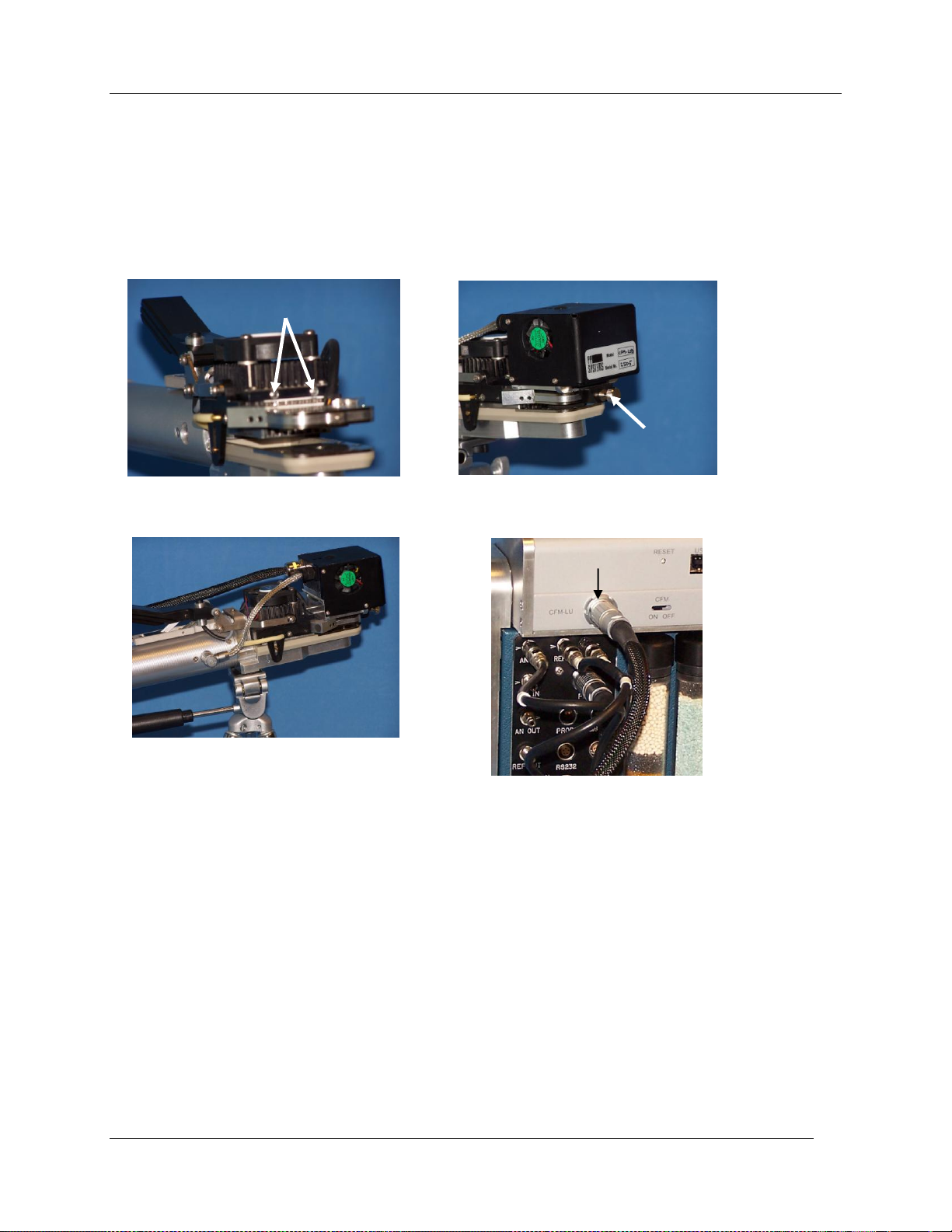
Measuring Chlorophyll Fluorescence with the CFM
(A)
(B)
2 Locating Peg Holes
Screw
Connector
(C)
(D)
From LED Light Unit
Connecting the CFM to CIRAS-2
All electrical and pneumatic connections must be made before powering up the CIRAS-2. Please pay
special attention when connecting all electrical connections to avoid problem associated with
damaged connectors (which are quite expensive).
1. Ensure that the plain glass window is fitted to the leaf cuvette as described earlier.
2. Fit the LED light unit to the leaf cuvette head. Slide the 2 locating pegs into the 2 holes on the
lower part of the black anodized heat sink (A). Gently tighten the screw connector on the end of
the light unit to the small screw protruding from the end of the leaf cuvette head until snug (B).
3. Connect the shorter grey LED electrical cable on the light unit into the 5 pin socket on the side of
the cuvette handle (C).
4. Connect the longer black cable from the LED light unit (14 pin Lemo connector) to the connector
labeled “CFM LU” on the back of the User Interface (D). For neatness, this cable can be twisted
gently around the main leaf cuvette electrical cable. DO NOT PLUG THIS CABLE INTO THE
“PLC” CONNECTOR ON THE CIRAS-2.
5. Connect leaf cuvette electrical cable to the CIRAS-2 connector labeled “PLC” (D).
6. Connect the leaf cuvette reference gas connectors to the “REF IN” and “AIR OUT” and the
analysis gas connector ot the “AN IN” connector on CIRAS-2 (D).
CIRAS-2 Operator's Manual Version 2.04
- 98 -
 Loading...