

Page 1

EGM-4 Environmental Gas
Monitor For CO
2
Operator’s Manual
Version 1.00
© 2002 PP Systems. All Rights Reserved
29th October 2002
Europe North America
PP Systems PP Systems Inc.
Unit 2, Glovers Court, Bury Mead Road. 241 Winter Street
Hitchin, Hertfordshire, SG5 1RT, U.K. Haverhill, MA 01830 U.S.A.
Tel: +44 1 462 453 411 Tel: +1 978 374-1064
Fax: +44 1 462 431 090 Fax: +1 978 374-0972
Email: [email protected]
Web Site: http://www.ppsystems.com
Page 2

This page left intentionally blank
Page 3

Table of Contents
Table of Contents
Table of Contents...........................................................................................3
Preface............................................................................................................5
System Calibration........................................................................................5
User Registration ..........................................................................................5
Warning Notice...............................................................................................6
Condensation Risk........................................................................................6
PP Systems’ Contact Information..................................................................7
Technical Specification.................................................................................8
Introduction....................................................................................................9
Measurement Principle..................................................................................9
Getting Familiar With The EGM-4 ...............................................................10
Front Panel.................................................................................................................... 10
Top Of EGM-4............................................................................................................... 10
Back Of EGM-4.............................................................................................................11
Environmental Sensor Inputs (I/O Ports).....................................................11
Analog Output.............................................................................................12
Current Output ............................................................................................12
RS232 Port..................................................................................................12
Soda Lime Absorber Column ......................................................................12
Soda Lime.........................................................................................................................12
Keypad........................................................................................................12
LCD Display................................................................................................13
Gas Ports....................................................................................................13
Charge Socket ............................................................................................13
Power Supply/Charger...................................................................................................... 13
Power Switch ..............................................................................................13
Operation......................................................................................................14
Main Menu ..................................................................................................16
1REC...........................................................................................................16
Stand Alone CO2 Analyser (Probe Type 0)......................................................................16
PP Systems Environmental Sensor Conversions: ...........................................................17
Environmental Monitor (Probe Types 1-6 and 10) ...........................................................18
PP Systems Environmental Sensor Conversions: ...........................................................19
Steady State Porometer (Probe T ype 7) .......................................................................... 19
Closed System Soil Respiration (Probe Type 8)..............................................................20
Oxygen (Probe Type 9) ....................................................................................................23
Open System Soil Respiration (Probe Type 11) .............................................................. 23
Calculation Of Fluxes For CFX And CPY Chambers .......................................................25
2SET...........................................................................................................25
1EGM................................................................................................................................25
2Z......................................................................................................................................26
Changing the Zero Type...................................................................................................26
Changing the Zero Time...................................................................................................26
3PMP................................................................................................................................26
4AV...................................................................................................................................27
5RECD..............................................................................................................................27
6ALM.................................................................................................................................27
Setting the Low CO2 Alarm Setpoint ................................................................................28
Setting the High CO2 Alarm Setpoint................................................................................28
EGM-4 Operator's Manual – Version 1.00
- 3 -
Page 4

Table of Contents
7VOUT..............................................................................................................................28
3CAL...........................................................................................................29
Connecting Calibration Gas To The EGM-4.....................................................................29
4DMP..........................................................................................................30
Screen Display..................................................................................................................30
Data Dump........................................................................................................................32
Record Structure...............................................................................................................32
Data Structure Based On Probe/Sensor s ......................................................................... 33
Error Codes ......................................................................................................................34
EGM Serial Outputs For Use With WINDOWS Data Transfer Program......35
5CLR...........................................................................................................35
6CLK...........................................................................................................35
Diagnostics and Initialisation......................................................................37
Diagnostics..................................................................................................37
Initialisation .................................................................................................37
Maintenance .................................................................................................38
Soda Lime Absorber Column ......................................................................38
Soda Lime.........................................................................................................................38
MATERIAL SAFETY DATA FOR SODA LIME.................................................................39
Servicing The EGM-4..................................................................................40
Fuse..................................................................................................................................40
Inside The EGM-4.........................................................................................................41
Infrared Source.................................................................................................................41
EPROM.............................................................................................................................41
ZERO Valve......................................................................................................................42
12V Lead Acid Battery......................................................................................................42
Battery Specification.........................................................................................................42
Removing The 12V Battery ..............................................................................................43
Air Sampling Pump...........................................................................................................43
Replacing The Air Sampling Pump................................................................................... 44
Cleaning The Air Sampling Pump ....................................................................................44
In-Line Hydrophobic Filter.................................................................................................45
EGM-4 Operator's Manual – Version 1.00
- 4 -
Page 5

Preface
Preface
It is extremely important that you take the time to review this operator’s manual prior to
installation and operation of the EGM-4 CO
caused which is not covered under our normal warranty policy.
System Calibration
• This product is shipped as a factory calibrated system. System calibration is not
required upon receipt from our factory.
• Familiarization with the docum entation and calibration procedures is r equired prior to
future recalibration. See section
• All calibration related questions may be directed directly to PP Systems at:
In North America
Telephone: +1 978.374.1064
Fax: +1 978.374.0972
Telephone: +44 (0)1462.453411
Fax: +44 (0) 1462.431090
Email: [email protected]
Gas Analyser. Otherwise, damage may be
2
of this manual.
3CAL
In Europe
User Registration
It is very important that
kept up to date. If you are a PP Systems’ user, please register yourself electronically on our
web site at http://www.ppsystems.com/Register.html
Only
REGISTERED
site. This section will contain important product information including hardware/software
updates, application notes, newsletters, etc.
users will be allowed access to our protected “U sers” section of our web
new customers register with us to ensure that our user’s list is
ALL
Thank you in advance for your cooperation.
The warrant y excludes all d efects in eq uipment
caused by incorrect installation, operation or
maintenance, misuse, alteration, and/or
accident.
EGM-4 Operator's Manual – Version 1.00
- 5 -
Page 6
Warning Notice
Warning Notice
This instrument must not be used in situations where its failure could result in injury or
death. For applications where failure of this instrument to function correctly would
lead to consequent ial damag e, the Analyser must be checked for correct operatio n and
calibration at intervals appropriate to the criticality of the situation.
This manual is pr ovided to help you install and operate the equipment. Every effort has been
made to ensure that the inf ormation contained in this manual is accurate and complete. PP
Systems does not accept any liability for losses or damages resulting from the use of this
information.
PP Systems' equipm ent warranty is lim ited to replac ement of defective components, and does
not cover injury to persons or property or other consequential damage.
This manual, and the infor mation contained in it, is copyright to PP Systems. No part of the
manual may be copied, stored, transmitted or reproduced in any way or by any means
including, but not limited to, photocopying, photography, magnetic or other mechanical or
electrical means, without the prior written consent of PP Systems.
The EGM-4 is covered under warranty for one complete year, parts and labour included.
This, of c ourse, is provided that the equipm ent is properly installed, operated and maintained
in accordance with written instructions (i.e. Operator's Manual).
The warranty excludes all defects in equipment caused by incorrect installation,
operation or maintenance, misuse, alteration, and/or accident.
If for som e reason, a fault is covered under warranty, it is the responsibility of the customer to
return the goods to PP Systems or an authorised agent for repair or replacement of the
defective part(s).
Condensation Risk
If condensation occurs in the analysis sam ple line, free water m ay enter the analyser causing
serious damage which will result in a very expensive repair. Theref ore, it is critical that you
periodically inspect the pipeline to be sure that condensed water does not enter the analyser.
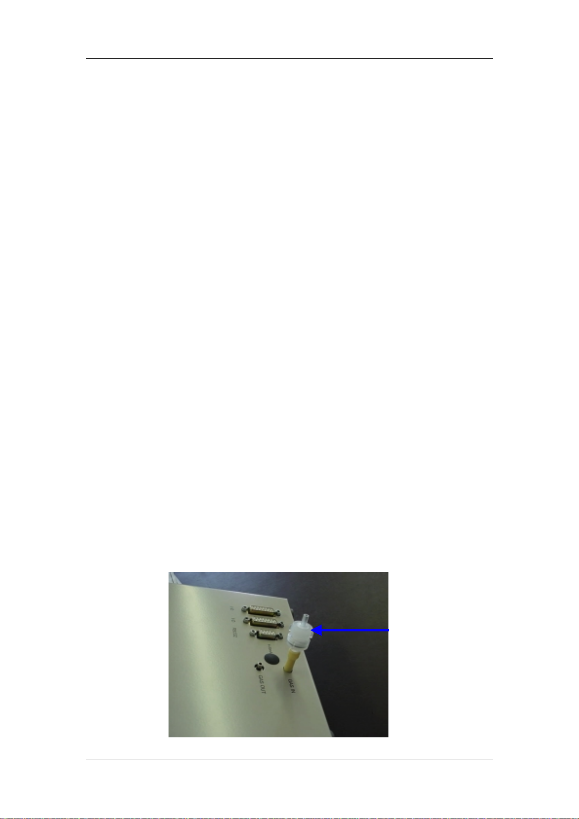
An external, in-line, hydrophobic filter is currently supplied with all EGM-4’s (starting in
October 2002) and is available to all exis ting EGM cus tom ers. It consis ts of a 3 m icron PT FE
hydrophobic filter (Cat. No. STD086) f itted inside an in-line filter holder ( Cat. No. STD101). If
there is any risk of water in the sample line, we strongly recommend fitting the external
hydrophobic filter supplied to the “Gas In” line on the EGM-4 (see below). In addition, the
filter must be checked regularly and replaced if dirty. Otherwise, blockage can occur. T he
filter holder is sealed by an “O” ring that should be kept lightly greased with silicone.
External hydrophobic
filter fitted to the “Gas
In” line to protect the
analyser from water.
EGM-4 Operator's Manual – Version 1.00
- 6 -
Page 7

Warning Notice
For maintenance instructions, see In-Line Hydrophobic Filter.
If condensation appears to be a problem, we suggest increasing the flow rate. If
condensation persists, it is then rec ommended that a PP Systems’ water vapour equilibrator
(Part No. CRS090) is used. This is constructed from a material that is very permeable to
water vapour but impervious to CO
. If this is placed in-line in the analysis pipe at the
2
sampling point, the water vapour concentration of the analysis air will be brought close to
ambient.
The problem may also be avoided by putting a suitable water drop out trap or drier in the
same position. Drierite (anhydrous Calcium Sulphate) is suitable.
which also absorbs CO
.
2
DO NOT
use Silica Gel,
Please note that any method used to remove excess water from the analysis
sample will render any humidity measurement incorrect.
If you have any questions whatsoever with regards to possible condensation risk,
contact PP Systems (See PP Systems’ Contact Information).
PP Systems’ Contact Information
Europe North America
PP Systems, Ltd. PP Systems, Inc.
Unit 2, Glovers Court, Bury Mead Rd. 241 Winter Street
Hitchin, Herts., SG5 1RT U.K. Haverhill, MA 01830 U.S.A.
Tel: +44 1 462 453 411 Tel: +1 978 374-1064
Fax: +44 1 462 431 090 Fax: +1 978 374-0972
Email: [email protected]
Web Site: http://www.ppsystems.com
EGM-4 Operator's Manual – Version 1.00
- 7 -
Page 8
Technical Specification
Analysis Method
Measurement
Range
(CO
)
2
%RH/Temperature
Sensor (Optional)
Accuracy (CO2)
Linearity
Stability
Sample Pump
Air Filter
Calibration
Control
CO2 Control
Alarm
Data Logging
Real Time Clock
Recording
Data Storage
Data Input/Output
Sensor Interface
Analog Output
Digital Output
(RS232)
General
Display
Power Supply
Gas Connections
Housing
Dimensions
Weight
Non-dispersive infrared with microprocessor control and linearisation.
0-1,000 ppm (µmol mol
0-2,000 ppm (µmol mol-1)
0-5,000 ppm (µmol mol-1)
0-10,000 ppm (µmol mol-1)
0-20,000 ppm (µmol mol-1)
0-50,000 ppm (µmol mol-1)
0-100,000 ppm (µmol mol-1)
RH: 0-100% RH
Accuracy: 2%
Temp: 0-45 °C
Accuracy: 0.5 °C
Measurements are automatically corrected for temperature and pressure.
1% (limited by calibration gas mixture).
1% FSD.
Periodic “Auto-Zero” resulting in automatic correction for sample cell
contamination, source aging, detector sensitivity variations and preamplifier gain changes.
Integral DC Pump
Filtered Sample Line (hydrophobic).
Default value preset in factory (Built-in Initialisation). Automatic
calibration via keypad if required.
High and Low Set points
Audio Alarm
Accuracy > 1 minute per month at 25
Automatic correction for month end and leap years.
Manual (by keypress) or automatic at user selected intervals between 1
and 250 minutes.
512 K Battery backed RAM (1,250 records).
Input available for external sensors (i.e. % RH, temperature, PAR, O
4-20 mA, 0-1 V, 0-2 V, 0-3 V, 0-4 V, 0-5 V (Linear)
9600 baud/8 data bits, 1 start bit/2stop bits/no parity
ASCII Format
High contrast 2 x 16 character LCD.
12 V, 2.0 Ah Rechargeable Lead Acid Battery. (Up to 6 hours continuous
operation)
Two gas ports (inlet and exhaust) for 1/8” (.125) ID tubing.
High Impact, Aluminium Enclosure.
158 W mm x 210 D mm x 62 H mm
1.5 kg.
Technical Specification
-1)
˚
C, operating temperature 0-70˚C.
)
2
EGM-4 Operator's Manual – Version 1.00
- 8 -
Page 9

Introduction
Introduction
The EGM-4 CO
Ah lead acid rechargeable battery providing up to 6 hours continuous use. For extended
operation in the field (> 6 hours), PP Systems can also provide an external power supply
cable that will allow you to connect up to an external 12 V battery. If interested, please
contact PP Systems (See
The EGM-4 is a high precision instrument for use in CO
greenhouses, environment contr ol room s, nur series and laboratories. Long term stability and
accuracy is ensured as a result of our unique “Auto-Zero” technology. The EGM-4 also
features inputs for additional sensors for measurement of O
Measurement Principle
Analyser is a portable oper ated unit that is powered by an internal 12 V, 2.0
2
PP Systems’ Contact Information
).
monitoring applications such as
2
, %RH, temperature, PAR, etc.
2
The EGM-4 CO2 is a non-dispersive, infrared gas Analyser that features an “
facility. Using infra-red gas analysis techniques, we can readily determine CO
Auto-Zero”
(Carbon
2
Dioxide) concentrations to within a few ppm and instantaneous meas urements are possible.
Gases with di-atomic molecules such as CO
For CO
one region of strong absorption is 4.26 m icrons. A source emitting strongly at this
2 ,
strongly absorbs photons in the infra-red range.
2
wavelength is a light bulb. If this is positioned at one end of a tube and at the other end is
placed a sensor that is sensitive to photons at 4.26 m icrons, we have a simple infra-red gas
Analyser. As carbon dioxide is passed down the sam ple cell, it absorbs some of the infra-red
and the sensor reading decreases. The “
Auto-Zero
” feature, which occurs at regular
intervals, allows for fast warm-up, adaptation to changing ambient conditions and excellent
stability of the CO
signal. The action of auto-zeroing minimizes the effects on span (gas
2
sensitivity) of sample cell contamination, source aging, changes in detector sensitivity and
changes in pre-amplifier gain.
The entire optical bench assembly (i.e. sample cell) is filtered and should never require
replacement.
To ensure proper operation, the EGM-4 MUST always
be operated in a vertical, upright position.
There are two CO
instruments are checked and calibrated at the concentration specified at time of order to
ensure that the readings are within 1% of that value. When an instrument is reset to its
default values (i.e. when the system is initialised, see
it returns to this setting.
It is important to note that the information contained in this documentation normally
refers to the latest firmware (EPROM) which can change over time. We recommend
that all users keep in contact with us from time to time to ensure that they are running
the most up to date system firmware.
measurement ranges in the EGM-4, 30,000 and 99,999 ppm. All
2
Error! Reference source not found.
),
EGM-4 Operator's Manual – Version 1.00
- 9 -
Page 10
Getting Familiar With The EGM-4
y
Getting Familiar With The EGM-4
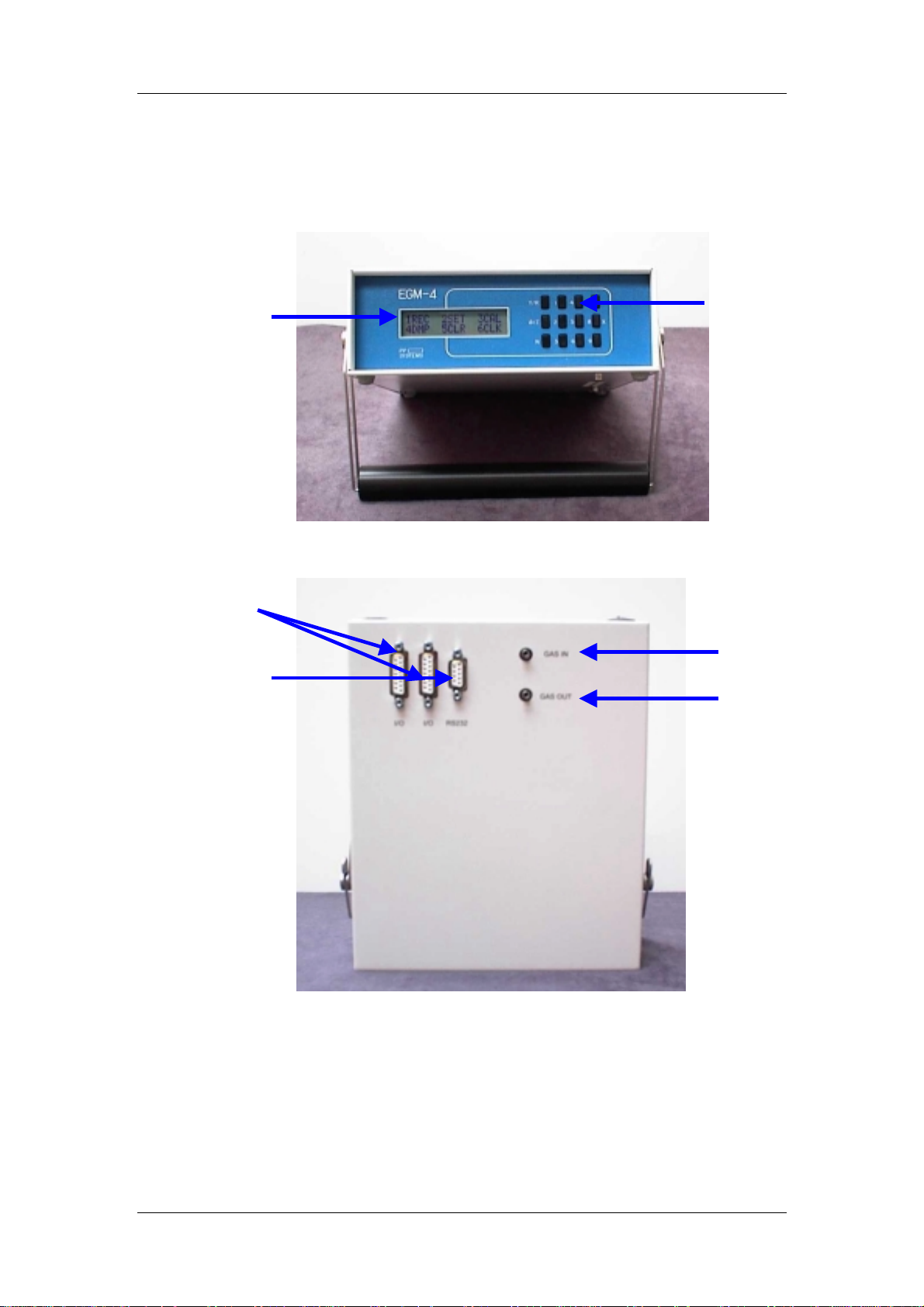
LCD Displa
(2 x 16)
Character
Front Panel
Sensor I/O
Connectors
RS232
Connector
Top Of EGM-4
Keypad
Gas In Port
Gas Out Port
EGM-4 Operator's Manual – Version 1.00
- 10 -
Page 11
Getting Familiar With The EGM-4
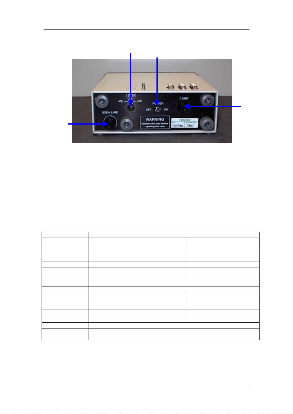
Soda
Lime
Cap
External Power/Charger
Connector
Power (On/Off)
Fuse
(1A)
Back Of EGM-4
Environmental Sensor Inputs (I/O Ports)
The EGM-4 has 2 environmental sensor inputs (I/O) to allow external sensors (i.e. soil
respiration chamber, % relative hum idity, temperature, PAR, etc.) to be used sim ultaneously.
All sensor inputs lines require 0-1V input. Note, the s ensor inputs are dis played in mV (i.e. 01,000 mV) instead of Volts.
If one of our environmental sensors is used with the EGM-4, it must be plugged into the
instrument prior to turning it on. T he EGM-4 autom atically detects the sensor c onnected as a
result of code resistors which are fitted to the 15 pin D Connector. T he code res istors f or our
environmental sensors are as follows:
Probe Type PP Systems Sens or Code Resistor
0 No Sensor Connected. The EGM-4 is
being used as a stand alone IRGA.
1 STP-1 Soil Temperature Probe
2 HTR-2 %RH/Temp/PAR Probe
3 HTR-1 %RH/Temp/PAR Probe
4 PAR-1 Sensor
5 PAR-1 (LUX)
6 SRM-1
7 Steady State Porometer (PMR-4) Not applicable. This is
8 SRC-1 Soil Respiration Chamber
9 RH/T/O2
10 RH and Temperature
11 CFX-1 Open System Soil Respiration
Chamber or CPY-3 Canopy Chamber.
If the sensor is not connected to the EGM-4 when first turned on, it will not be
Note.
detected and the subsequent displays will not be available.
Not applicable. This is
determined by keypad
selection.
100 KΩ
56 KΩ
36 KΩ
27 KΩ
20 KΩ
15 KΩ
determined by keypad
selection.
9.1 KΩ
20 KΩ
5.6 KΩ
4.3 KΩ
EGM-4 Operator's Manual – Version 1.00
- 11 -
Page 12

Getting Familiar With The EGM-4
Analog Output
The EGM-4 has a 0-5V analog output. The default output is s et at 0-5V. However, this can
be changed by the user (if required) to any value in between (i.e. 0-2V, 0-3V, 0-4V). (See
7VOUT
).
Current Output
If required, current output (4-20 mA) is available. Inside the EGM-4, there is a 2 pin
connector labelled CN7 on the PC075-1 circuit board. Consult with PP Systems for further
information. A modification to the enclosure is required to gain access to connector CN7.
RS232 Port
The EGM-4 has one RS232 connector used for transferring stored data to a PC or laptop
computer. To transfer stored data from the EGM-4 to an external PC, connect the data
transfer cable (supplied by PP Systems) between the RS232 connector on the EGM-4 and
the 9 pin serial connector on the PC. Data transfer sof tware (supplied by PP Systems) steps
you through the data transfer process. See
transfer. If required, this can be made up by the user if required. See table below:
15 PIN D Socket on
EGM-4
Pin 2 Pin 2
Pin 5 Pin 5
15 Pin D Socket on
PC
Data Dump
for more information on data
Soda Lime Absorber Column
The absorber c olumn is labelled “Soda Lim e” on the rear panel. It contains a CO2 scrubbing
desiccant known as Soda Lim e. When air pass es through this column, it rem oves all of the
CO
from the air stream. The “Auto-Zero” fac ility built into the EGM-4 periodic ally switches
2
the flow of gas from the Analyser through this column to check the Analyser zero. This
routine ensures long term stability and accuracy of the CO
corrects for s uch things as sample cell contam ination, source aging, detector sensitivity and
changes in electronics.
Analyser. It automatically
2
Soda Lime
Soda lime is used to remove CO2 from air entering the EGM-4. It is supplied as selfindicating granules (1-2.5m m) that turn from green to brown as it becomes exhausted. The
contents of the absorber column should be replaced when it is 2/3rds exhausted (brown).
Soda Lime cannot be regenerated and should be discarded when exhausted. For accurate
measurements and calibration, it is absolutely critical that the EGM-4 absorber column is not
exhausted. If the soda lime is becoming exhausted, it will cause the ZERO to be performed
on non-ZERO air causing an error in the calibration.
When exhaus ted, the Soda Lime Cap should be rem oved along with the foam filter pad (with
the EGM-4 facing upwards) and the contents discarded. W hen replacing the soda lime, we
recommend using a funnel to ensure that the desiccant fills the absorber column. Leave
approximately 1” from the end of the column to allow the foam pad and cap to be refitted.
! CAUTION !
WASH YOUR HANDS AFTER HANDLING SODA LIME
Keypad
The keypad consists of 12 k eys. There are ten keys that are labelled
few keys that have additional functions. The
and to record measurements. In addition, the
display to the next. The N key is normally used to return to the Main Menu from
EGM-4 Operator's Manual – Version 1.00
(Yes/Record) key is used to accept settings
Y/R
key is pressed to advance from one
Y/R
- 12 -
. Also, there are a
0-9
Page 13

Getting Familiar With The EGM-4
Measurement Mode, r eject settings or to step back through the menus. T he
to toggle from one display to another in Measurement Mode.
key is used
8/X
LCD Display
The EGM-4 features a 2x16 character, backlit LCD display.
Gas Ports
There are two gas ports located on the top of the EG M-4. Each port is designed f or use with
1/8” (.125) ID tubing. One gas port is labelled “Gas In” and the other “Gas Out”. The
sampling line should be fitted to the “Gas In” port us ing 1/8” tubing. T he “ Gas O ut” line s hould
be left open to atm osphere to allow the sample air to exhaust without restriction. Note, f or
closed system soil respiration measurements using our SRC-1 chamber, one gas line is
connected to the “Gas In” port and the other to the “Gas Out” port.
Charge Socket
The charge socket is labelled “12V DC” on the rear panel of the EGM-4. The AC
Adapter/charger supplied by PP Systems plugs into this sock et to charge the internal 12V 2.0
Ah lead acid battery.
Power Supply/Charger
All systems are supplied com plete with an AC Adapter/Charger designed specifically for use
with the EGM-4 for charging the internal 12 V 2.0 Ah lead acid battery. This unit has the
following technical specification:
Input
Output
Power Indicator
Dimensions
Weight
100-240 V ~ 50-60 Hz
15 V @ 2.7 A
Green LED
10.5 cm x 6.5 cm x 4.5 cm
0.3 kg
!!! WARNING !!!
USE OF POWER SUPPLIES AND BATTERY CHARGERS OTHER THAN
THOSE SUPPLIED BY PP SYSTEMS FOR THE EGM-4 WILL INVALIDATE
THE WARRANTY.
Power Switch
To power up the EGM-4, the On/Off Switch should be toggled to the “On” position. To turn
the instrument off, the switch should be toggled to the “Off” position.
EGM-4 Operator's Manual – Version 1.00
- 13 -
Page 14
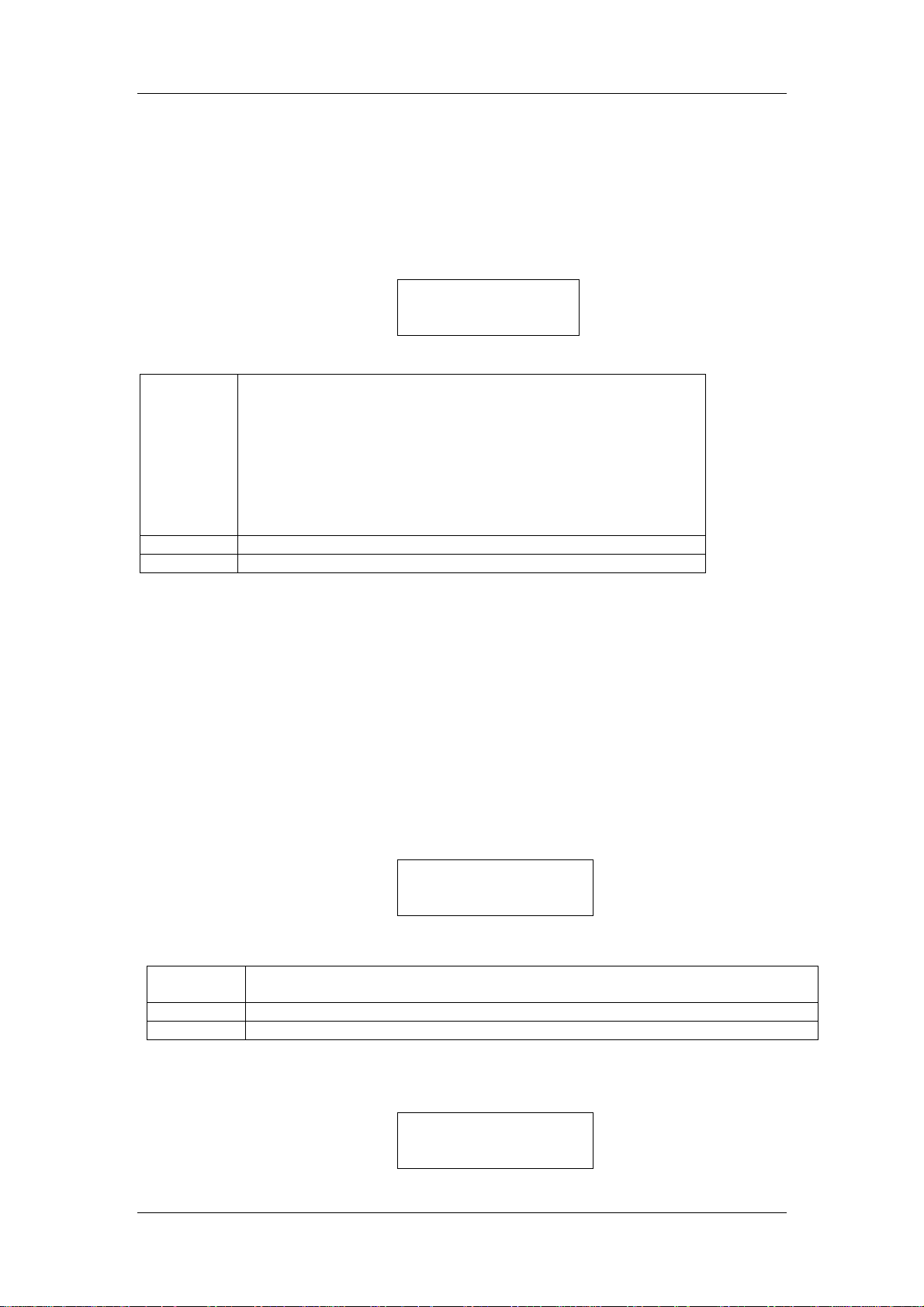
Operation
Operation
The EGM-4 is a m enu driven instrum ent.
used with the EGM -4, they MUST be electrically connected to one (or both) of the I/O
ports prior to turning the instrument on.
through its normal warm-up period that takes approximately 5 minutes. Immediately after
powering up the system, the following is displayed:
Whereas:
EGML
Or
EGMH
Or
PMR
0456
V1.30
During warm-up, there is a delay of approxim ately 45 seconds to allow for calibration of the
electronics and then the instrument proceeds to warm-up until the Analyser temperature
reaches 50 ˚C. A final Zero check is then performed before proceeding to the Main Menu.
Also during warm-up, several system checks are performed. The “Checksum” message is set
to a factory default value of 123456. If this is inc orrect as when a new version of firm ware is
first installed, a “CHECKSUM ERROR SEE MANUAL” m essage is displayed. If this occurs,
simply press any key to proceed to the Main Menu. From the Main Menu, pr ess key 0 to reinitialise the system (See Initialisation).
The next display will be dependent on whether or not any external sensor s are being used
with the EGM-4.
If the EGM-4 is being used on its own, the following will be displayed:
Where:
C2000
1V=2000
R150
If the EGM-4 is being used with an external sensor (i.e. SRC-1 Soil Respiration Chamber),
the following will be displayed:
Refers to an EGM-4 with a measurement range of 30,000 ppm.
Refers to an EGM-4 with a measurement range of 99,999 ppm.
Refers to PMR-4 Steady State Poromter.
Refers to the serial number of the EGM-4
Refers to the firmware (EPROM).
Corresponds to the last calibration gas c oncentration. After DEFAULT, it is the
original range specified by the end user.
Range of the voltage signal corresponding to the CO
Number of records stored in memory.
Note. If any external sensors/probes are to be
When the ins trum ent is f irst powered up, it will go
PP SYSTEMS C2002
EGML 0456 V1.30
C2000 1V=2000
mV INPUTS R150
concentration.
2
C2000 1V=2000
PROBETYPE 8 R150
EGM-4 Operator's Manual – Version 1.00
- 14 -
Page 15
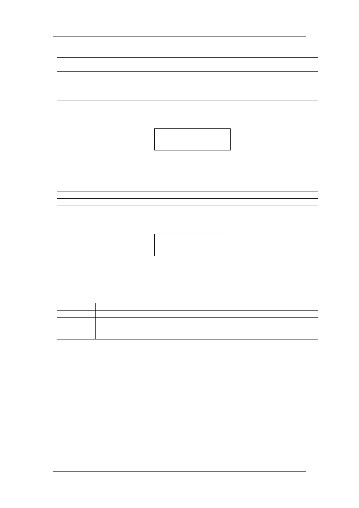
Operation
Where:
C2000
Corresponds to the last c alibration gas concentration. After DEFAULT, it is
the original range specified by the end user.
1V=2000
PROBETYPE 8
Range of the voltage signal corresponding to the CO
Refers to the probe/sensor connected to the EGM-4. For a list of probe
concentration.
2
types, see Environmental Sensor Inputs (I/O Ports).
R150
Number of records stored in memory.
If the EGM-4 is being used as a porometer (i.e. PMR-4), the following will be displayed:
C2000 1V=2000
POROMETER R150
Where:
C2000
Corresponds to the last c alibration gas concentration. After DEFAULT, it is
the original range specified by the end user.
1V=2000
POROMETER
R150
Range of the voltage signal corresponding to the CO
Refers to the PMR-4.
Number of records stored in memory.
concentration.
2
After all system checks have been performed and the s ystem achieves warm-up, the EG M-4
Main Menu is displayed as follows:
1REC 2SET 3CAL
4DMP 5CLR 6CLK
If the instrument was just powered up, the display will show “WARM UP DELAY
Note.
TEMPERATURE = XX” until the ins trument achieves its warm up temperature of 50 ˚C prior
to the Main Menu.
While in Measurement Mode, the following key presses can be performed:
Key
Z/0
Y/R
8/X
N
To:
Perform a manual Zero.
Record a measurement and place it in memory.
Changes to a different display (See section
1REC
Return to the Main Menu.
).
Refer to the following sections for more information on menus and displays.
EGM-4 Operator's Manual – Version 1.00
- 15 -
Page 16
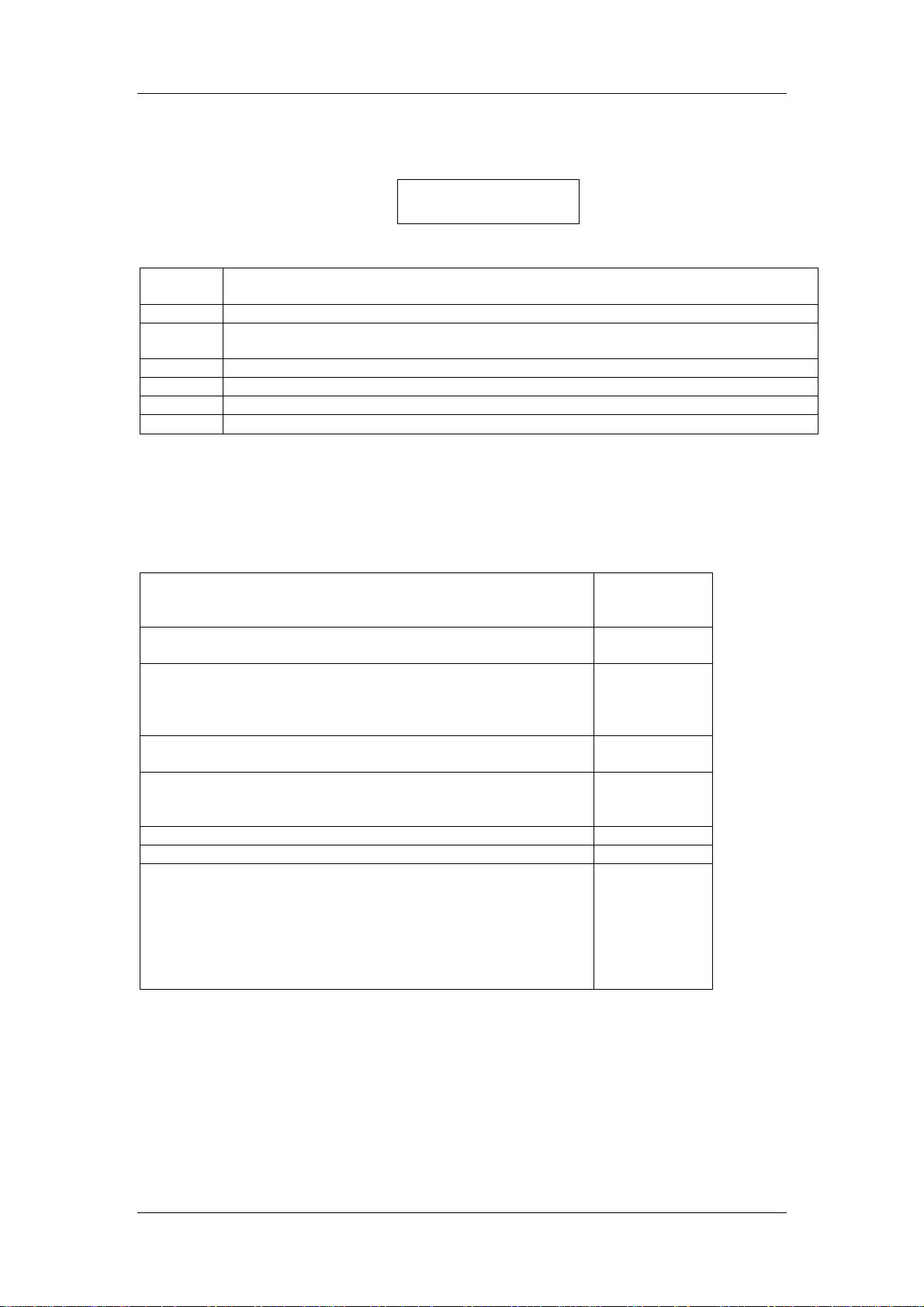
Operation
Main Menu
There are 6 options available to the user when the Main Menu is displayed as follows:
Where:
Press
Key
1
2
3
4
5
6
Each option is discussed in further detail below.
To
Go Into Measurement Mode. See
Change system settings (i.e. zero type and time interval, recording type, alarm
settings, etc.). See
To calibrate the Analyser. See
To dump stored data to a PC or to view data on the LCD display. See
Clear system memory. See
Set/check the system clock (date and time). See
1REC 2SET 3CAL
1REC
2SET
3CAL
5CLR
4DMP
6CLK
1REC
To begin recording, press k ey 1. Please note, the EGM-4 display is dependent upon which
probe type is connected to it. The following table illustrates the Probe Types:
If the EGM-4 is used as a: Then The
Probe Type is
set to:
Stand Alone CO2 Analyser. See Stand Alone CO2 Analyser
(Probe Type 0).
Environmental Monitor
(With one of our Environmental Sensors such as %RH,
temperature, PAR, O
(Probe Types 1-6
Steady State Porometer. See
(Probe Type 7)
Closed System Soil Respiration
(i.e. SRC-1 Soil Respiration Chamber). See
Soil Respiration (Probe Type 8)
RH/T and O2 probe 9
RH and Temperature 10
Open System Measurement
(i.e. CFX-1 Soil Respiration Chamber, CPY-3 Chamber). See
Open System Soil Respiration (Probe Type 11).
Important Note.
supplied with the EGM-4. If an existing EGM-4 user purchas es an environmental sensor from
us, it may be necessary to set the probe type (see
Most instruments are s upplied with the probe type already set if a sensor is
, etc.). See
2
and 10)
Environmental Monitor
Steady State Porometer
Closed System
).
1EGM
0
1-5
7
8
11
Stand Alone CO2 Analyser (Probe Type 0)
Immediately after pressing key 1, the instrument will automatically perform a zero check.
Once completed and assuming no problems with the zero, the instrument will proceed to
EGM-4 Operator's Manual – Version 1.00
- 16 -
Page 17
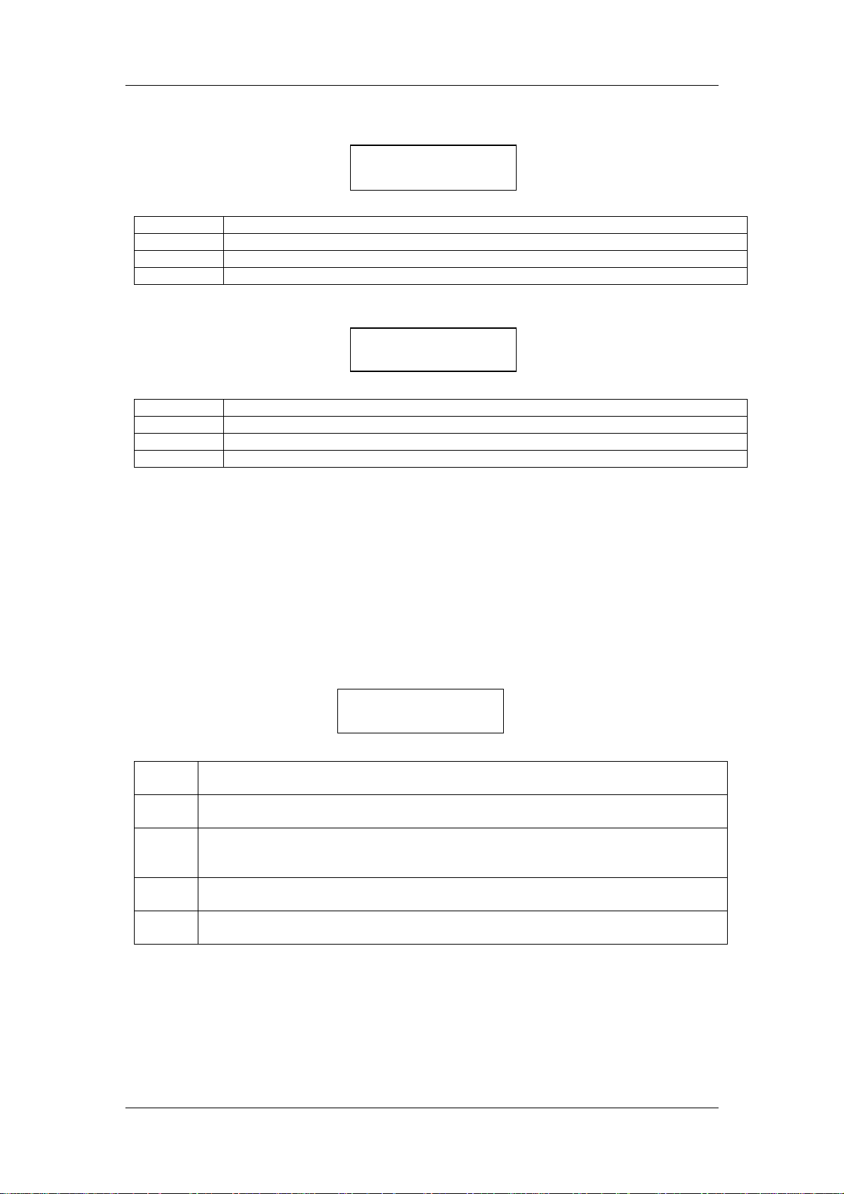
Operation
“Measurement Mode” where the CO
pressure and probe type are displayed as follows (
value (plus Humidity if sensor is pres ent), atmospheric
2
Display 1
):
C 365 H 13.5
A 0987 P 00
Where:
C
H
A
P
CO
concentration (ppm)
2
Humidity (mb).
Only if a sensor is present.
Atmospheric Pressure (mb)
Probe Type
Press key 8/X to view record number, plot number, date and time (
Display 2
):
REC 0001 PLOT 00
03-04 12:40
Where:
REC
PLOT
03-04
12:40
Record Number (up to 9999).
Plot Number (up to 99)
Date (3
rd
day of April)
Time (12:40 PM)
The record num ber res ets each tim e the instr ument starts or when the memor y is cleared. It
counts up to 9999 and then resets automatically to 1. The internal EGM-4 memory allows
data storage of up to 1,000 records.
Please note, when the memory is full, it overwrites
the oldest records.
Note.
If the plot number needs to be changed, pres s key N when Display 2 above is shown
and enter the plot number desired. Next, pres s the Y key to continue. To return to Display 1
press key 8/X twice. Only the plot number can be changed at this point and the record
number automatically resets to 1 when the plot number changes.
Additional information m ay be viewed on the LCD display if required. Press key 8/X to view
signals (mV) from any external sensors that may be connected to the EGM-4 (
Display 3
):
A0244 B0333 0444
D0555 E0666
Where:
A0244
B0333
0444
Signal (mV) from sensor connected to
Environmental Sensor Inputs
.
Signal (mV) from sensor connected to
Environmental Sensor Inputs
.
Signal (mV) from sensor connected to
Environmental Sensor Inputs
. Due to the lim its of the dis play, the letter C is not
on the 15 pin D connector. See
Pin 1
on the 15 pin D connector. See
Pin 2
on the 15 pin D connector. See
Pin 3
displayed next to the signal.
D0555
E0666
Signal (mV) from sensor connected to
Environmental Sensor Inputs
.
Signal (mV) from sensor connected to
Environmental Sensor Inputs
.
on the 15 pin D connector. See
Pin 4
on the 15 pin D connector. See
Pin 5
PP Systems Environmental Sensor Conversions:
The following conversions need to be m ade to determ ine ac tual m easurem ents of PAR, %RH
and temperature when using PP Systems’ environmental sensors.
PAR Sensor
%RH Sensor
Temperature
mV x 3 = PAR Level (µmol m
mV / 10 = %RH
mV / 20 = Temperature (˚C)
EGM-4 Operator's Manual – Version 1.00
- 17 -
-2 s-1
)
Page 18
Operation
To return to the Main Menu while in Measurement Mode, simply press the N key.
Environmental Monitor (Probe Types 1-6 and 10)
Immediately after pressing key 1, the instrument will automatically perform a zero check.
Once completed and assuming no problems with the zero, the instrument will proceed to
“Measurement Mode” where the CO
values are displayed as follows (
Where:
C
H
T
Q
RH
CO
concentration (ppm)
2
Humidity (mb).
Air Temperature (
PAR (µmol m
-2 s-1
Relative Humidity (%RH)
If the instrument was just powered up, the display will show “WARM UP DELAY
Note.
TEMPERATURE = XX” until the ins trument achieves its warm up temperature of 50 ˚C prior
to entering into Measurement Mode.
Press key 8/X to view record number, plot number, date and time (
Where:
REC
PLOT
03-04
12:40
Record Number (up to 9999).
Plot Number (up to 99)
Date (3
rd
day of April)
Time (12:40 PM)
The record num ber res ets each tim e the instr ument starts or when the memor y is cleared. It
counts up to 9999 and then resets automatically to 1. The internal EGM-4 memory allows
data storage of up to 1,000 records.
the oldest records.
Note.
If the plot number needs to be changed, pres s key N when Display 2 above is shown
and enter the plot number desired. Next, pres s the Y key to continue. To return to Display 1
press key 8/X twice. Only the plot number can be changed at this point and the record
number automatically resets to 1 when the plot number changes.
Additional information m ay be viewed on the LCD display if required. While in Measurement
Mode with the CO
concentration displayed, subsequent presses of the 8/X key will show 3
2
additional displays as follows:
Press key 8/X key again to view external sensor signals (in mV) as follows (
value (plus Humidity if sensor is present) and sensor
2
Display 1
):
C 365 H 13.5 T24.3
Q 1200 RH 65.3
Only if a sensor is present.
o
C)
)
Display 2
):
REC 0001 PLOT 00
03-04 12:40
Please note, when the memory is full, it overwrites
Display 3
Axxxx Bxxxx xxxx
Dxxxx Exxxx
):
EGM-4 Operator's Manual – Version 1.00
- 18 -
Page 19
Operation
Where:
A
B
xxxx
D
E
Signal (mV) from sensor connected to
D connector. See
Environmental Sensor Inputs
Signal (mV) from sensor connected to
D connector. See
Environmental Sensor Inputs
Signal (mV) from sensor connected to
D connector. See
Environmental Sensor Inputs
Signal (mV) from sensor connected to
D connector. See
Environmental Sensor Inputs
Signal (mV) from sensor connected to
D connector. See
Environmental Sensor Inputs
on the 15 pin
Pin 1
on the 15 pin
Pin 2
on the 15 pin
Pin 3
on the 15 pin
Pin 4
on the 15 pin
Pin 5
.
.
.
.
.
PP Systems Environmental Sensor Conversions:
The following conversions need to be m ade to determ ine ac tual m easurem ents of PAR, %RH
and temperature when using PP Systems’ environmental sensors.
PAR Sensor
%RH Sensor
Temperature
mV x 3 = PAR Level (µmol m
mV / 10 = %RH
mV / 20 = Temperature (˚C)
To return to the Main Menu while in Measurement Mode, simply press the N key.
-2 s-1
)
Steady State Porometer (Probe Type 7)
Immediately after pr essing key 1, the instrument will display the following message to allow
the sensors to time for alignment (
Display 1
KEY 2 = HUMIDITY
SENSOR BALANCE
After approximately 3 seconds, the following is displayed to allow entry of record and plot
number if required (
Display 2
):
REC 0001 PLOT 00
03-04 12:40
Where:
REC
PLOT
03-04
12:40
Record Number (up to 9999).
Plot Number (up to 99)
Date (3
rd
day of April)
Time (12:40 PM)
Note.
If the plot number needs to be changed, pres s key N when Display 2 above is shown
and enter the plot number desired. Next, pres s the Y key to continue. To return to Display 1
press key 8/X twice. Only the plot number can be changed at this point and the record
number automatically resets to 1 when the plot number changes.
):
EGM-4 Operator's Manual – Version 1.00
- 19 -
Page 20
Operation
To proceed to the Measurement Display, press the 8/X key
(Display 3):
I 22.3 O28.4 T22
Q1645 F245 G 0234
Where:
I
O
T
Q
F
G
Inlet Relative Humidity (%RH)
Outlet Relative Humidity (%RH)
Porometer Temperature (˚C)
PAR (µmol m
-2 s-1
)
Flow Rate (ml/min)
Stomatal Conductance (
mmol (H2O) m
-
-
s
²
¹ )
The stomatal conductance calculation uses an exact determination of the energy balance.
To return to the Main Menu while in Measurement Mode, simply press the N key.
Closed System Soil Respiration (Probe Type 8)
Before starting any m easurem ents with the SRC-1 Soil Res piration Cham ber, see the section
on Condensation Risk at the beginning of this m anual to ensure that you do not encounter
any problems related to water in the analyser.
Immediately after pressing k ey 1, the instrument will perform zero checks prior to displaying
the following message (
Display 1
The soil respiration rate is calculated by plotting the rate of change in the chamber CO
concentration. The user has the option of saving the full data used in fitting the soil
respiration rate curve or the final res ults. If you want to save the full set of data, press k ey 1.
Note, data is collected every 4.8 seconds. If 1 is selected (ALL), the internal memory will
allow you to store approximately 80 minutes of continuous data. Since there is typically
several minutes in between meas urem ents, you could expect to store approximately ½ a days
work. If 2 is selected, only the final results will be saved and recorded.
Next, choose linear or quadratic fitting for the soil respiration data (
unsure which option to c hoose, we recommend option 2QUAD (quadratic fitting) . For more
information on this, please see the SRC-1 Soil Respiration Operator’s Manual.
Please note. If a quadratic fit is selected and the ppm change is less than 0.2ppm/second, a
linear fit is used.
The system always starts up with the SRC default values . Press key 1 to change the volum e,
key 2 to change the area, etc. (
):
SOIL RESP.DATA
RECORD 1ALL 2END?
DATA F ITTING
1LINEAR 2 QUAD.?
Display 3
):
1V: 1171 2A: 78
3V/A*100 1491
Display 2
2
). If you are
EGM-4 Operator's Manual – Version 1.00
- 20 -
Page 21
Operation
Where:
1V:
2A
3V/A*100
Volume of the system up to 999,999 (ml)
Area exposed up to 9999 (cm
3
)
Volume/Area. This is automatically updated when there is a change to 1
(Volume) or 2 (Area). Also, if this value is changed directly, 1 (Volume) and 2
(Area) are set to maximum. The default value is 1491.
Press key Y to advance to the next dis play. Press key 1 to change the time, k ey 2 to change
the CO
concentration or key 3 to change the approximate air temperature
2
(Display 4):
1DT:120 2DC:50
3 APPROX TEMP 25
Where:
1DT:
Time for which the change in the chamber CO
concentration is monitored
2
(seconds). The minimum and maximum values are 30 and 999 seconds
respectively.
2DC:
The maximum change allowed in CO
concentration from time zero at which
2
point the final measurement is made (ppm)
3 APPROX
The approximate air temperature (°C)
TEMP
Press key Y to advance to the next display
(Display 5):
PLOT NO = 0
Y OR NEW VALUE
Where:
PLOT
Plot Number (up to 99)
Note.
If the plot number needs to be changed, s imply enter the new value and press key Y
when Display 5 above is shown. T o return to Display 1 press key 8/X twice. Only the plot
number can be changed at this point and the rec ord number automatically resets to 1 when
the plot number changes.
The next display is as follows
(Display 6):
CHAMBER FLUSHING
HOLD IN AIR 03
At this stage, the SRC-1 chamber should be held in the air to allow it to flush out prior to
placing it on the soil. The number in the bottom right (03 in this case) is a count from 0-15 in
1.6 second increments. When completed, the following is displayed
(Display 7):
PLACE ON SOIL
PRESS Y TO START
EGM-4 Operator's Manual – Version 1.00
- 21 -
Page 22
Operation
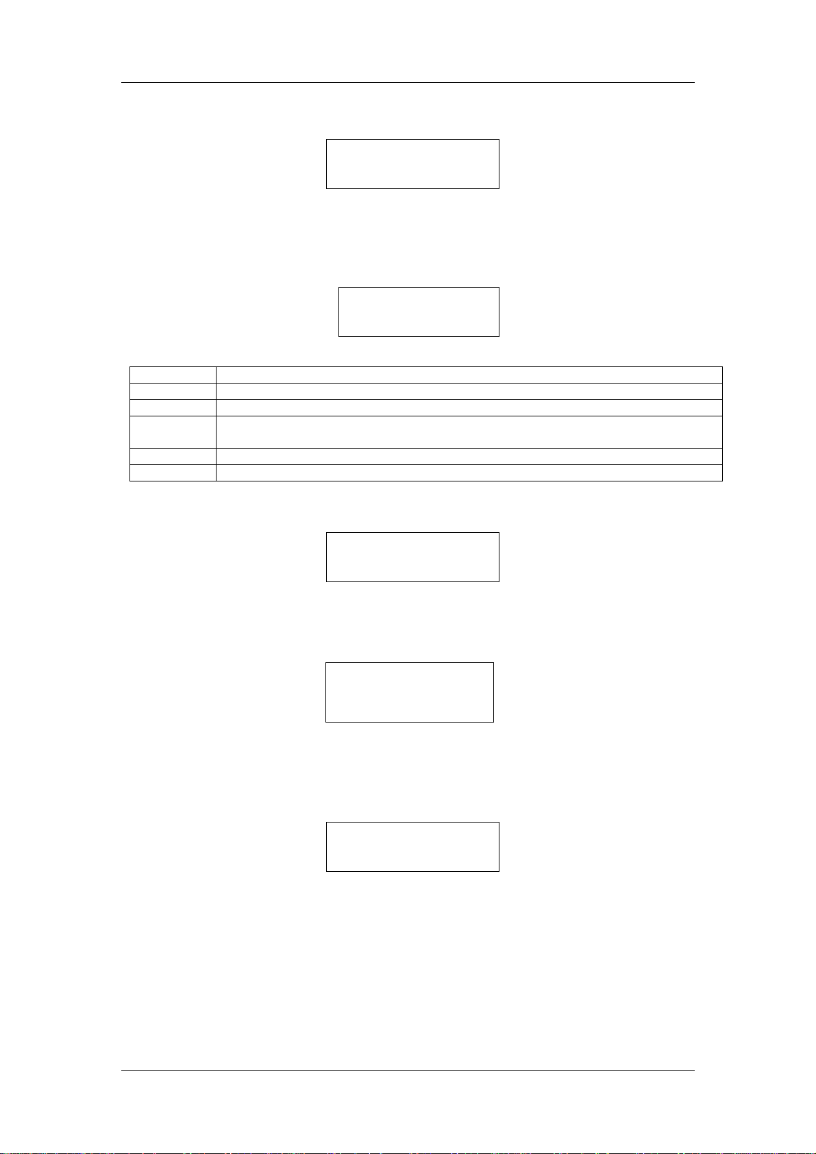
After placing the SRC-1 cham ber on the soil, pres s the Y key. The following will be displayed
(Display 8)
:
EQUILIBRATION
PLEASE WAIT 03
After approxim ately 5 seconds, the measurement will com mence. Before f inal calculation of
soil respiration rate (g (CO
data sets. The measurement display is as follows
) m2 Hour) can be achieved, the EGM-4 m ust have acc um ulated 4
2
(Display 9):
C00395 H14.7 T22
A02.11 Q0000 110
Where:
C00395
H14.7
T22
A02.11
Q0000
110
Current measured CO
Humidity concentration
concentration (ppm)
2
if sensor is present
(mb)
Soil Temperature if probe is present (˚C)
exchange (Assimilation) rate (g (CO2) m2 Hour). The maxim um rate that
CO
2
can be recorded is 99.99 g (CO
PAR (µmol m
-2 s-1
)
) m2 Hour.
2
The elapsed time of measurement (seconds)
Please Note.
If the DC or DT exceeds the set values, the following message is displayed:
MEASUREMENT END
RECORD Y/N
The following m essage will be shown with the quadratic fit if the C term in the quadr atic fitting
expression (Y = a + bx + cx
2
) is greater than 0.1 x b.
NON LINEAR FIT
At this stage, the us er is given the opportunity to save the measurem ent even though the DC
an DT settings were exceeded. If you still want to save the meas urement, press key Y. If
not, press key N. After making your selection, the following is displayed:
REMOVE FROM SOIL
THEN PRESS Y KEY
The measur ement process begins as des c ribed above.
If a ZERO is required, it will be
Note.
performed in between measurements. At any time, a key press of N will return you to the
display that shows Volume, Area, etc. (Display 3 above) and the settings can be changed if
required. A subsequent press of the N key will return you to the Main Menu.
To return to the Main Menu while in Measurement Mode, simply press the N key.
For more information on the theory and calculation of soil respiration, please refer to the
SRC-1 Soil Respiration Chamber Operator’s Manual.
EGM-4 Operator's Manual – Version 1.00
- 22 -
Page 23
Operation
Oxygen (Probe Type 9)
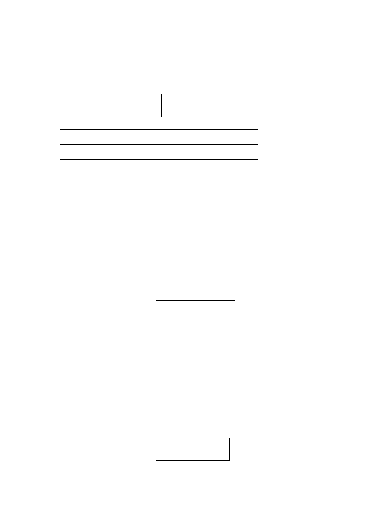
Immediately after pressing key 1, the instrument will automatically perform a zero check.
Once completed and assuming no problems with the zero, the instrument will proceed to
“Measurement Mode” where the CO
is present) and sensor values are displayed as follows (
Where:
C
H
T
O%
RH
CO
concentration (ppm)
2
Humidity (mb).
Air Temperature (
O2 concentration (%)
Relative Humidity (%RH)
and O2 value (plus Humidity and Temperature if sensor
2
Display 1
):
C 365 T24.3
O% 31.0 RH 65.3
Only if a sensor is present.
o
C).
Only if a sensor is present.
Open System Soil Respiration (Probe Type 11)
Before starting any m easurements with the CFX-1 or CPY-3 chambers , see the section on
Condensation Risk at the beginning of this m anual to ensure that you do not encounter any
problems related to water in the analyser.
Immediately after pressing key 1, the instrument will display the following message
(
Display 1
Where:
Select the appropriate chamber (CPY-3 or CFX-1) . If one of the CPY-3 chambers is selected,
it is necessary to enter or to check that the area c overed by the chamber is corr ect. Note, the
entry is in cm
smaller, the calculated flux will be the chamber flux.
After performing a Zero, the next display will be as follows (
1:5L
2:20L
3:100L
CFX
):
CPY 1:5L 2:20L 3:100L
4:CFX
Select 1 if operating our CPY-3 chamber
with 5 Litre/min flow.
Select 2 if operating our CPY-3 chamber
with 20 Litre/min flow.
Select 3 if operating our CPY-3 chamber
with 100 Litre/min flow.
Select 4 if operating our CFX-1 Soil
Respiration Chamber
2
up to 9999 or approximately 1 m2. If 9999 is entered when the true area is
Display 2
):
REC 0001 PLOT 00
03-04 12:40
EGM-4 Operator's Manual – Version 1.00
- 23 -
Page 24
Operation
Where:
REC
PLOT
03-04
12:40
Record Number (up to 9999).
Plot Number (up to 99)
Date (3
rd
day of April)
Time (12:40 PM)
Note.
If the plot number needs to be changed, pres s key N when Display 2 above is shown
and enter the plot number desired. Next, pres s the Y key to continue. To return to Display 1,
press key 8/X twice. Only the plot number can be changed at this point and the record
number automatically resets to 1 when the plot number changes.
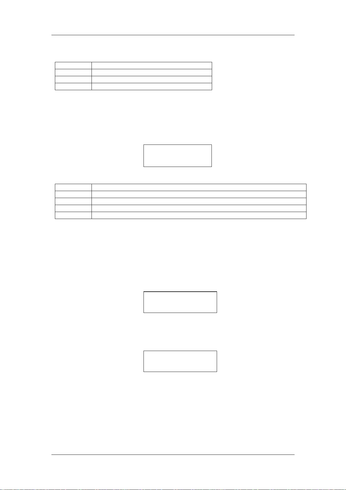
To proceed to the first measurement display, press the 8/X key
(Display 3):
R00345 D+0020 T22
A06.15 F0300
Where:
R
D
T
A
F
Reference CO
concentration (ppm)
2
Difference between Reference and Analysis gas (ppm)
Temperature of the CFX-1 or CPY-3 Chamber (˚C)
exchange (Assimilation rate) (µmol m2 s-1).
CO
2
Flow Rate (ml/min)
If you press the 8/X k ey, the standard EGM-4 data is displayed (i.e. CO
, H2O, etc.). W ith the
2
CPY-3 chambers, the atmos pheric pressure Annnn is replac ed by the PAR reading (Qnnnn).
If the EGM-4 is fitted with our optional humidity/temperature sensor, the H
O fluxes are
2
calculated and recorded but are not shown on the displays.
The EGM-4 is an abs olute Analyser. When used with the CFX-1 Soil Respir ation Chamber,
an internal solenoid (built into the CFX-1) switches the gas stream from Reference and
Analysis during 30 second intervals. As such, a m inimum of 45 seconds m ust elapse before
valid data is available. At the conclusion of measurement, the following is displayed:
MEASUREMENT END
RECORD Y/N
At this stage, the user is given the opportunity to save the measurem ent. If you want to save
the measurem ent, pr es s key Y. If not, press key N. After making your selection, the following
is displayed:
REMOVE FROM SOIL
THEN PRESS Y KEY
The measur ement process begins as des c ribed above.
If a ZERO is required, it will be
Note.
performed in between measurements. At any time, a key press of N will return you to the
display that shows Volume, Area, etc. (Display 3 above) and the settings can be changed if
required. A subsequent press of the N key will return you to the Main Menu.
To return to the Main Menu when any of the above displays are shown, simply press the N
key.
EGM-4 Operator's Manual – Version 1.00
- 24 -
Page 25

Operation
Calculation Of Fluxes For CFX And CPY Chambers
Both the CFX-1 and CPY-3 chambers us e Honeywell mass flowmeters that are calibrated at
STP which is 0
O.
for H
2
Convert the flow (V) measured in m l min
of (A) cm
= ( V x 10000 ) / ( A x 22.414 x 1000 x 60) = (V / A ) x 7.436 x 10
With a CO
∆C x (V / A ) x 7.436 x 10
and with an H
∆H x (V / A ) x 7.436 x 10
For CO
For H
2,
O, to convert to g H2O m2 h-1 , multiply by 64.87.
2
o
C and 1013mb. Results are given in µmol m
-1
2
to mol m-2 s
differential between the inlet and outlet of ∆C ppm, the CO2 flux is:
2
O differential between the inlet and outlet of ∆H mb, the H2O flux is:
2
to convert to g CO2 m2 h
-1
(Molar Volume at STP is 22.414 l.)
-1
, multiply by 0.1584.
at STP through the chamber with an exposed ar ea
-3
µmol m-2 s
-3
mmol m-2 s-1 .
-1
-2 s-1
for CO2 and in mmol m
-2 s-1
-3
2SET
Press key 2 from the Main Menu if you need to:
• Select/change probe types the EGM-4 (
• Select/change the EGM-4 Zero (2Z).
• Enable/disable sampling pump (
3PMP).
• Determines within which range of outputs the average is to be taken (
• Change the instrument recording feature, automatic vs. manual (
• To set the high and low alarm (
6ALM
)
• To change the analog voltage output, 1-5V, (
1EGM2Z: 3PMP 4AV
5RECD 6ALM 7VOUT
1EGM
Press 1EGM to set the EGM-4 displays according to intended application. The EG M-4 can
be used as a:
1. Stand alone CO
2. CO
IRGA with external sensor (probe) attached (i.e. SRC-1 Soil Respiration
2
Chamber, CFX-1, CPY-3, HTR-2 RH/T emp/PAR Probe, PAR-1 Sensor, O
etc.).
3. Steady State Porometer
If the instrum ent is being used on its own, press key 1. If an external sensor/pr obe is used
simultaneously, press k ey 2. If the EGM-4 is being used as a porometer , press key 3. After
making your selection, an asterisk (*) will be placed next to your selection. The EGM-4 will
automatically recognize which sensor or probe is connec ted by way of code resistors which
are built into the sensor connector (See Environmental Sensor Inputs (I/O Por ts) . Pres s the Y
key to return to the 2SET menu.
IRGA
2
1EGM
).
7VOUT
).
4AV
5RECD
).
)
Sensor,
2
EGM-4 Operator's Manual – Version 1.00
- 25 -
Page 26
Operation
2Z
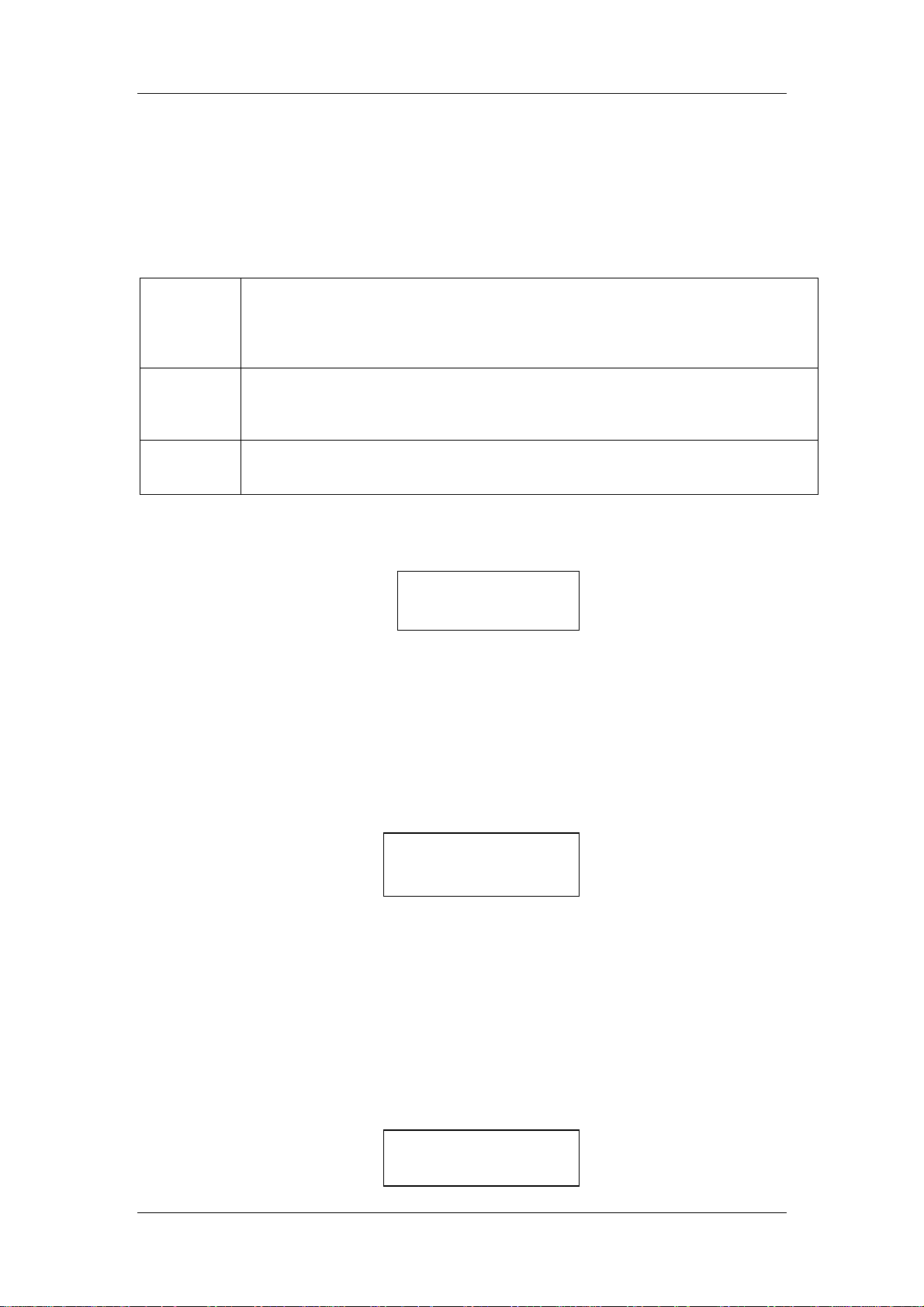
Press 2ZERO to change the zero type and the time interval for performing zeros.
Changing the Zero Type
Press key 2 (2ZERO) and then key 1 to change the zero type used by the EGM-4. At
present, there are 3 types of zeros that can be performed:
Auto
Manual
EXT
An asterisk (*) indicates which ZERO type is selected. By default, the ZERO TYPE is set to
AUTO which is what we recommend.
To change the ZERO TYPE, press k ey 1 for AUTO, k ey 2 for MANUAL or key 3 for EXT.
Immediately after pressing the k ey, the asterisk (*) will be displayed next to your selection.
This will be the ZERO TYPE that will be used by the EGM-4 until changed again. Press key
Y to return to the 2SET menu.
This is the recom mended ZERO type. The EGM-4 performs a Zero on start up,
then again after 2 minutes, then again after 4 mor e minutes, then after 8, etc up
to a maxim um inter val set by the ZEROTIME. ZEROT IME by default at start up is
20 minutes but it can be set from 1 to 30 minutes. This is the default m ode on
startup.
If selected, the EGM-4 will perform an initial ZERO when first s tarted. After that,
the user is responsible for performing ZEROS by pressing the 0 key while in
Measurement Mode.
minutes, one will be performed automatically.
A ZERO can be initiated by pulling DATA/ZERO REQ (Pin 10) line LOW.
(Connect to Ground Pin 8) Hold for 3 sec onds and then break ground connection.
If no ZERO occurs after 40 minutes, one will be performed automatically.
Note, if the user fails to perform a ZERO after 40
ZEROTYPE *:AUTO
2:MANUAL 3:EXT
Changing the Zero Time
Press key 1 (1ZERO) and then key 2 to change the Auto-Zero time.
Zero time is the interval between Zeros in m inutes when ZERO TYPE is set to Auto. If the
displayed time is correct, simply press the Y key. If you want to change the ZERO TIME,
press key N and enter a value up to a maximum of 40.
leading zeros are required (i.e. 05 for 5 minutes).
display. To accept, press the Y key.
ZEROTIME = 40
Y=OK N=NEW VAL
Note, for values less than 10,
The new value will be updated on the
3PMP
Press 3PMP to enable/dis able the internal sampling pump. By default, the sample pum p is
on.
SAMPLE PUMP ON
Y/OK N/CHANGE
EGM-4 Operator's Manual – Version 1.00
- 26 -
Page 27

Operation
If required, the internal pump can be turned off by pressing the N key.
If static sam pling is selected, the user can inject sam ples directly into the sample cell rather
than having the sample pumped through it. For minimum volume, the samples should be
injected into the cell exhaust through the port labelled “G as Out”. A minimum volume would
be about 5 ml. A warning is given 2 minutes and 1 m inute prior to the instrum ent perfor ming
a ZERO followed by the pump turning on for a ZERO. On com pletion of the Analyser ZERO,
the pump will again switch off.
STATIC SAMPLING
Y/OK N/CHANGE
4AV
The outputs from the CO2 sensors are normally subjected to an averaging process. This
consists of diff erencing the c urrent r eading and the stored average r eading (both raw data). If
the difference exceeds the average limit, then the current reading replaces the average.
Otherwise, the current reading is incorpor ated into the average. The average reading is then
linearized etc. to give the measured concentration. If AV is s et to 0, then aver aging is dis abled
giving instantaneous readings. The averaging band is increased as AV is increased, up to a
maximum of 999 units.
The AV is automatically set to 1 unit for s oil respiration and static sampling measurements.
The AV defaults to 30 units without a probe.
Press 4AV to change the AV.
If you want to change the AV value, press key N and enter a value up to a maximum of 999.
AV. LIMIT = 30
Y/OK N=NEW VAL
5RECD
This controls the recording in the EGM-4. Records can be recorded manually or
automatically at set time intervals. Press Key 5 to set the recording type.
To change the r ecording from MANUAL (M) to AUT OMATIC (A) and vic e versa, press k ey 1.
If M is displayed, the time interval (2INT) is set 0 by default. A key press of 1 will change the
recording type to A (Automatic) and the time inter val (2INT) will change to 1 (1 minute) by
default. To change the time inter val for automatic recording, press key 2 and enter a value
(not to exceed 720 minutes).
(i.e. 005 for 5 minutes).
The EGM-4 is set to MANUAL recording by default.
1REC:M 2INT: 0
Note, leading zeros are required fo r values less than 100
6ALM
There are both high and low alarm facilities built into the EGM-4. A 2 pin header type
connector (CN6) is located on the internal EG M-4 circuit board for controlling the alarm . All
EGM-4’s are cur rently supplied with the alarm dis abled as the jumper is f itted to just one pin
EGM-4 Operator's Manual – Version 1.00
- 27 -
Page 28
Operation
on CN6. To enable the alarm, simply fit the jumper to both pins on CN6. For acc ess and
location of CN6, see Inside The EGM-4. Note, the alarm facilities are not available with Probe
Types 7 or higher (i.e. porometer and soil res piration). Press key 3 to set the Low and High
CO
alarm setpoints.
2
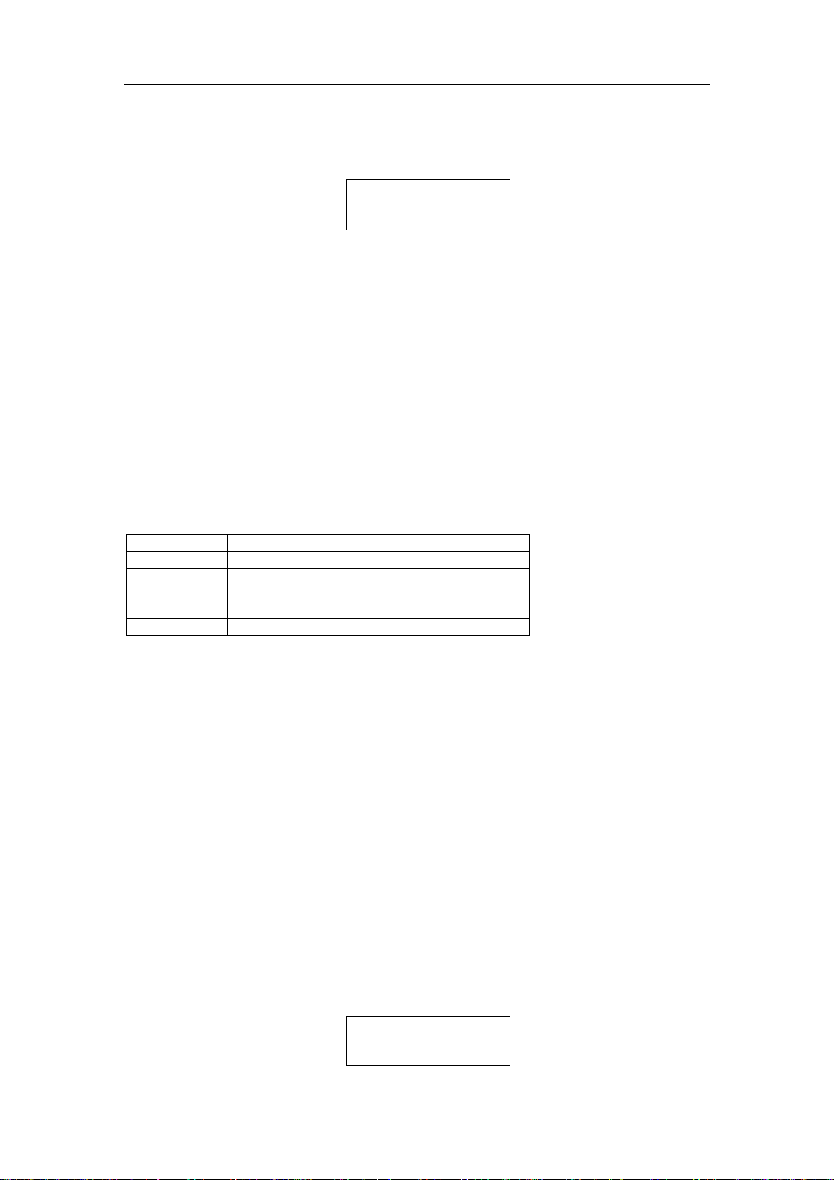
1:LOCO2 = 250
2:HICO2 = 2000
Setting the Low CO2 Alarm Setpoint
Press key 3 (3ALM) and key 1 to set the low CO2 alarm setpoint in ppm . The display will
show ?????. Enter the required value.
than 1000 (i.e. 00200 for 200).
setting of 250 ppm . The reas on for this is that a typical low CO
the following scenarios:
• Low or no air flow.
• Absorber column exhausted (soda lime).
• Zero valve failure.
• Source failure.
However, past history has shown that some customers want to work at lower CO
concentrations. As a result, lower alarm settings can be set up by the user if requir ed. If the
low alarm is set to 250 ppm, the low alarm operates when the self-check ing facility finds any
of the following system faults:
Error Code Reported fault
1 Zero to low
2 CO2 < 250 ppm
3 Analyser temperature out of range (too cold)
4 Analyser temperature out of range (too hot)
5 RH > 90%
The above error codes are ac companied by corresponding displays and the error codes are
written to the records. Note, with the porom eter and soil respiration chambers (SRC-1 and
CFX-1), the display warnings still occur but there is no alarm.
The low alarm signal comes out on Pin 7 and is buffered (i.e. able to drive a load).
Note, leading zeros are required for values less
The EGM-4 is supplied with a factory default low alarm
value is the result of one of
2
2
Setting the High CO2 Alarm Setpoint
Press key 2 to set the high CO2 alarm setpoint. The display will show ?????. Enter the
required value.
The default EGM-4 high alarm setpoint setting is 2000. As long as the high alarm is set
900).
to the maximum CO
value, when the CO
Note, leading zeros are required fo r values less than 1000 (i.e. 00900 for
ppm range of the instrum ent, the alarm is inactive. If set to a lower
2
concentration exceeds the high setting, the alarm will activate.
2
The high alarm signal comes out on Pin 13 and is not buffered.
7VOUT
Press key 7 (7VOUT) to check/set the analog voltage output. These settings control the
voltage output from the D/A converter in the EGM-4.
EGM-4 Operator's Manual – Version 1.00
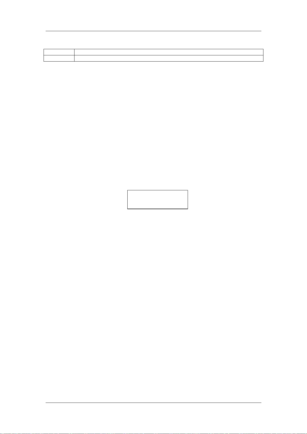
D/A 1V = 2000 ppm
Y=OK 1/ 2 NEW VAL
- 28 -
Page 29
Operation
Where:
D/A 1V Selects the maximum voltage output of the EGM-4 (1-5V)
2000 Corresponds to the CO2 concentration (ppm).
The FSD (Full Scale Deflection) analog output value can be set from 1 to 5V. Press key 1
and enter any value between 1 and 5 to set the analog output to the value required. Press
key 2 if you want to change the CO
concentration corresponding to the analog output value.
2
As in the display above, the EGM-4 would be set up with an analog output of 0-1V
corresponding to a measurement range of 0-2,000 ppm.
By default, the analog voltage output is 0-5V. If the displayed values are correct, simply press
the Y key to return to the 2SET menu.
Note. The voltage output must be set to 5V in order for the current output (4-20 mA) to
work properly. If the voltage output is changed to any other value (i.e. 2, 3 or 4V), the
current output facility will not work correctly and should not be used.
3CAL
To calibrate the EGM-4, press key 3.
The EGM-4 will display a value. Before proceeding, it is critical that:
• The absorber column is properly seated in its manifold
• The soda lime is fresh.
• The EGM-4 has been on for at least 30 minutes.
• The Gas Out port is unobstructed.
Connecting Calibration Gas To The EGM-4
During calibration, the signal from the CO2 detector is referenced against a gas of k nown CO2
concentration. The EGM-4 calibration procedure uses two reference points:
1. Zero CO
2. Span Gas (a user-defined CO
composition).
It is therefore vital that both of these references ar e accurate. For greater accuracy, cylinder
mixtures should be acc urate to +/- 1% and traceable to NIST standards. The zero gas will
only be accurate if the soda lime in the absorber column is fresh.
Assuming that a calibration gas mixture is used to calibrate the EGM-4, follow these
instructions:
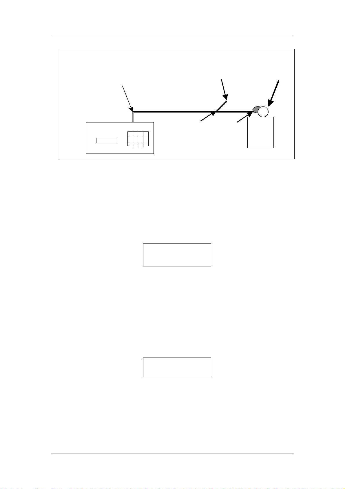
1. To avoid excess pres sure in the sample cell and possible damage to the Analyser, you
must connect the s ample line with a “T” piece between the calibration gas mixture and the
“Gas In” port on the EGM-4 as follows:
(generated from air that has been scrubbed through soda lime).
2
CO2 CONC = 2000
CORRECT (Y-N)?
concentration, normally a cylinder of certified CO2
2
EGM-4 Operator's Manual – Version 1.00
- 29 -
Page 30
Operation
f
Gas In
Port
Excess gas o
approx. 250 ml/min
Pressure
Regulator
EGM-4
In-line “T” piece
to vent excess
Shut-Off
Valve
CO2
Gas
Cylinder
2. T he pressure regulator should be s et to a very low pressure and there should be a slight
flow excess gas venting from the open “T” Piece (approx. 250 ml/min).
3. Press key N and enter the CO
This value must m atch the certified CO
concentration of the calibration gas that you are using.
2
concentration of the calibration cylinder and be
2
similar or higher than the anticipated m easurement range of the instrument (i.e. it is best
to calibrate the instrument with a reference gas containing 350 - 450 ppm CO
measuring around 350 ppm CO
).
2
when
2
4. The EGM-4 will then perform a ZERO. At completion of successful ZERO, a similar
message to the following will be displayed.
CO2 CONC = 1050
KEY0 WHEN STEADY
5. At this point, all you are looking for is that the CO
displayed value may not be the value you entered in step 1 above.
concentration is steady.
2
When this value
Note, the
is steady (i.e. not changing by more than 1 ppm after 30 seconds), press the 0 key.
6. Calibration is complete. The new calibration and linearization constants are stored in
non-volatile memory.
4DMP
Press key 4 to view/transmit stored data.
Stored data can be viewed on the instr um ent LCD display or transm itted to your PC computer
using our data transfer sof tware. The EG M-4 will store up to 1,000 records in memory.
when the memory is full, the oldest record will be overwritten each time additional
records are taken.
1:SCREEN DISPLAY
2:DATA DUMP 1-2?
Note,
Screen Display
To view stored data on the LCD display, press key 1. The latest stored record is displayed
first. Each record has 3 different displays associated with it as follows:
EGM-4 Operator's Manual – Version 1.00
- 30 -
Page 31

Operation
Display 1
REC 0000 PLOT 01
04-01 11:52
Where:
Record Number
REC
PLOT
04-01
11:52
Plot Number
Date (4
Time
th
day of January)
Press the 8/X key to proceed to the next display:
Display 2
A0000 B0000 C0000
D0000 E0000
Where:
mV signal from sensor (Pin 1).
A
B
C
D
E
mV signal from sensor (Pin 2).
mV signal from sensor (Pin 3).
mV signal from sensor (Pin 4).
mV signal from sensor (Pin 5).
Press the 8/X key to proceed to the next display:
Display 3
C 950
A 0992 P00
Where:
CO
C
Atmospheric Pressure
A
Probe Type
P
(ppm)
2
A key press of 8 steps you through the 3 above displays before taking you to the next record
in memor y. Af ter all rec ords have been displayed, a mess age “No Mor e Records In Store” is
displayed before returning you to the Main Menu.
from one display to the same di splay for the previous record
Note. A key press of Y will step you
. For instance, if Display 3
of record number 5 is displayed on the LCD, a key press of Y will step you to Display 3 for the
previous record (Record 4). Therefore, if you are only interested in viewing the CO
concentration for each record:
1. Press key 4 (4DMP).
2. Press key 1 (Screen Display).
3. Press the 8 key to display the CO
concentration for the last stored record.
2
4. Press the Y key to view previous records.
2
EGM-4 Operator's Manual – Version 1.00
- 31 -
Page 32

Operation
A key press of N ends the screen display.
If there are no stored records, the m essage
Note.
“NO MORE RECORDS IN STORE” will be displayed before returning you to the main menu.
Note, some of the displays will vary according the probe type connected.
Data Dump
To transm it stored data from the EGM-4 to a PC, you must use the data transfer cable and
software supplied with the system. Step by step instructions on transferring data from the
EGM-4 to the PC are contained in the software Help file.
When the RS232 transfer cable is properly connected and after you followed the instructions
contained in software, press 4DMP and then key 2 on the EGM-4 to transfer the data.
Complete data dump to PC takes approximately 70 seconds. Alternatively, the data dump
can be initiated from a PC while the EGM-4 c ontinues to collect data. If ZERO TYPE is NOT
set to external control, this can be initiated by a low on the Data Request. There are no
displays and the EGM-4 returns to measuring after completion.
Sending <KSP>Z<CR> signifies completion. DATA DUMP may be terminated by pressing
key N. Oldest records are always sent first.
Record Structure
A single record consists of 60 digits. Real time and stored data is output in the following
format:
M/R Plot
M 1 1 28 1 13 19 968 0 000.0 0000 0000 0000 0000 0000 0000 00 00 991 0
R 1 2 28 1 13 21 930 0 000.0 0000 0000 0000 0000 0000 0000 00 00 991 0
M 1 3 28 1 13 23 956 0 000.0 0000 0000 0000 0000 0000 0000 00 00 991 0
M 1 4 28 1 13 25 941 0 000.0 0000 0000 0000 0000 0000 0000 00 00 991 0
R 1 5 28 1 13 27 946 0 000.0 0000 0000 0000 0000 0000 0000 00 00 991 0
No.
Rec
Day Mo Hr Min CO2
No
Ref
H20
RHT A B C D E F G
Ref
H
AP PT
Where:
M/R
M = Real Time Measurement
R = Record from memory
Plot No.
Rec No.
Day
Mo
Hr
Min(utes)
CO2 Ref
H20 Ref
RHT
Temp
A
B
C
D
E
F
G
H
AP
PT
0-99
1-9999
1-31
1-12 (January - December)
1-24 (based on 24 hour clock)
0-59
reading in parts per million (ppm = µmol mol-1)
CO
2
O reading in millibars (mb)
H
2
Temperature of RH sensor if fitted
Temperature (˚C).
See
Data Structure Based On Probe/Sensors
See
Data Structure Based On Probe/Sensors
See
Data Structure Based On Probe/Sensors
See
Data Structure Based On Probe/Sensors
See
Data Structure Based On Probe/Sensors
See
Data Structure Based On Probe/Sensors
See
Data Structure Based On Probe/Sensors
See
Data Structure Based On Probe/Sensors
Atmospheric pressure in millibars (mb)
Probe Type See
for more information.
1REC
If there are no stored records , the m essage “ NO MORE RECO RDS IN ST ORE” will be
Note.
displayed before returning you to the main menu.
EGM-4 Operator's Manual – Version 1.00
- 32 -
Page 33
Operation
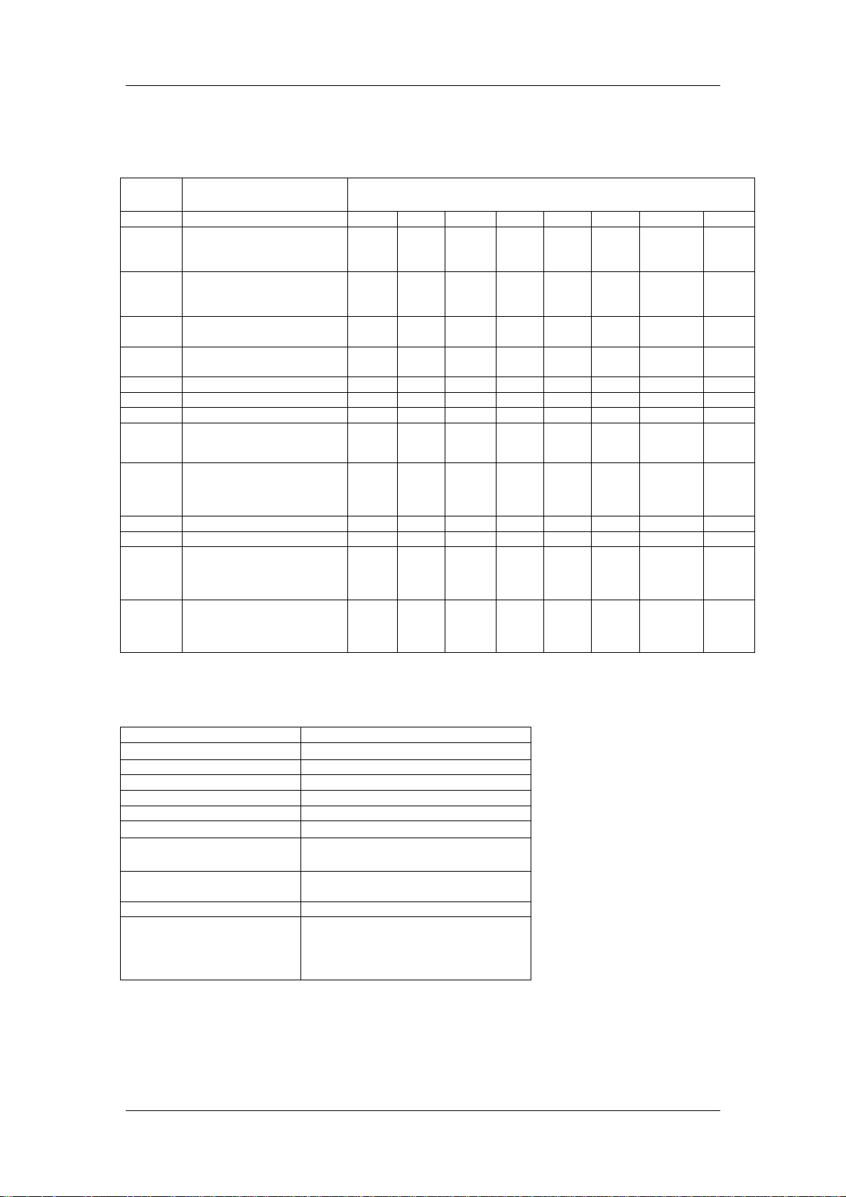
Data Structure Based On Probe/Sensors
Please note.
The data structure, particularly columns A-J described above, is dependent
upon the probe/sensor that is connected to the EGM-4.
Probe
Type
0 No Sensor Connected.
1 STP-1 Soil Temperature
2 HTR-2 %RH/Temp/PAR
3 HTR-1 %RH/Temp/LUX
4 PAR-1 Sensor
5 PAR-1 LUX
6 Solarimeter
7 Steady State Porometer
8 SRC-1 Soil Respiration
9 OP-1 Oxygen Sensor
10 50Y %RH/Temp Sensor
11 CFX-1 Open System Soil
11 CPY-3 Canopy
Further description of the data output is as follows:
PAR
% RH %
Evaporation Rate mmol m2 s-1 x 1000
Temperature ˚C
Flow ml min-1
GS (Stomatal Conductance)
SR Rate (Assimiliation)
DC (Change in CO2
concentration )
DT (Change in time) seconds
+/- In column H, if 00 is output, this
Description of Sensor
Connected
The EGM-4 is being used
as a stand alone IRGA.
Probe or CH15T RH/T
Probe
Probe
Probe
(PMR-4)
Chamber
Respiration Chamber
Assimilation Chamber
Output Data Units
µmol m-2 s
mmol (H
A B C D E F G H
mV
Pin 1
0000
PAR
0000
PAR
0000
PAR
0000
PAR
0000
PAR
0000
PAR
0000
PAR
0000
-1
O) m
2
SRC-1: g (CO2) m2 Hour
CPY-3 & CFX-1: µmol m
ppm
represents increase in CO2
(respiration). If it is 01, it represents
uptake).
CO
2
Each Column is described as follows
mV
Pin 2
0000
%RH
000.0
%RH
000.0
%RH
0000
%RH
In
000.0
%RH
0000
Evap
Rate
0000
Evap
Rate
0000
-
-
s
²
¹
mV
Pin 3
0000
Temp.
000.0
Temp.
000.0
Temp.
000.0
Temp
000.0
Temp.
000.0
Temp.
000.0
Temp.
000.0
-1
2 s-1
mV
Pin 4
0000
%RH
Out
000.0
DC
0000
DC
0000
DC
0000
mV
Pin 5
0000
mV
Pin 5
0000
Flow
000.0
DT
0000
Flow
000.0
Flow
000.0
In column G, a flow multiplier is output to provide true flow rate (1 or 10).
GS
0000
SR
Rate
00.00
SR
Rate
00.00
SR
Rate
00.00
+/- SR
Flow
Multiplier
Flow
Multiplier
Rate
00=+
01 = -
+/- SR
Rate
00=+
01 = -
+/- SR
Rate
00=+
01 = -
EGM-4 Operator's Manual – Version 1.00
- 33 -
Page 34

Operation
Error Codes
Error code infor mation is stored and output with data and can be located at the end of the
data string. The following is a list of current Error Codes:
Error
Code
00 Normal Operation Not Applicable Not Applicable
01 Zero read to low
02 CO2 less than 250
03 Analyser
04 Analyser
05 %RH > 90%
06 Battery voltage to
Description Possible Faults Remedy
(<2500)
• Absorber column not
properly fitted.
• Exhausted soda lime.
• Zero valve failure.
• Source/detector failure.
• Fit properly into
manifold.
• Change soda lime.
• Contact PP
Systems. (see
PP
Systems’ Contact
Information
)
• Contact PP
Systems. (see
PP
Systems’ Contact
)
PP
)
ppm
• Genuine low CO
2
concentration.
• Absorber column not
properly fitted.
• Exhausted soda lime.
• Zero valve failure.
• Source/detector failure.
Information
• Not Applicable.
• Fit properly into
manifold.
• Change soda lime.
• Contact PP
Systems. (see
Systems’ Contact
Information
• Contact PP
Systems. (see
PP
Systems’ Contact
)
PP
temperature < 50 ˚C
• Possible thermostat
failure.
Information
• Contact PP
Systems. (see
Systems’ Contact
)
PP
temperature > 60 ˚C
• Possible thermostat
failure.
Information
• Contact PP
Systems. (see
Systems’ Contact
)
PP
• If an RH sensor is fitted, a
reading above 90% could
mean condensation.
Information
• Contact PP
Systems. (see
Systems’ Contact
Information
• Battery voltage < 10.5v • Re-charge battery
low
EGM-4 Operator's Manual – Version 1.00
- 34 -
Page 35
Operation
EGM Serial Outputs For Use With WINDOWS Data Transfer Program.
On Starting:
<SP>B, EGM4,Serial Number, Firmware version<CR>
<SP>=Space, <CR>=Carriage return.
Then during the delay period at the start:
<SP>I, NN <CR>
Where NN is the same as the count on the EGM display.
During Warm up
<SP>W,TT<CR>
Where TT is the cell temperature.
During ZERO
<SP>Z.NN<CR>
Where NN is the same as the EGM display count.
During Diagnostics a data string is transmitted through the RS232:
<SP>D,CCCCC,ZZZZZ,HHHH,HTHT,ANLT,INPA,INPB,INPC,INPD,INPE,ATMP<CR
>.
(These values are the reads from the A/D converters and have not been scaled.)
Where:
CCCCC Current Analyser reading
ZZZZZ Stored Analyser reading during last zero.
HHHH Reading of the internal humidity sensor (optional).
HTHT Reading from the temperature sensor (optional).
ANLT Analyser temperature sensor reading.
INPA-E Corresponds to the mV inputs from external sensors.
ATMP Reading from the pressure transducer (mb).
5CLR
To clear data stored in memory, press key 5.
To clear the entire database, press the Y key twice. For data safety reasons, you will be
asked to “Press Key 0 To Confirm”. Press the 0 key to clear. The message “Database
Cleared” is displayed before returning you to the main menu. If you do not want to clear the
database, simply press the N key.
CLEAR DATABASE
(YY-N)?
6CLK
To view/set the EGM-4 real time c lock, press the 6 key. The following message should be
displayed:
EGM-4 Operator's Manual – Version 1.00
RESET TIME (Y-N)?
13-12-01 16:51
- 35 -
Page 36

Operation
The date is displayed as day/month/year and the time is displayed on a 24 hour format. The
display above shows December 13, 2001 and 4:51 PM. If the time is correct, press the Y key.
Otherwise, press key N and enter the appropriate date and time. Leading zeros must be
entered if required for date and time (i.e. if the time is 8:00 AM, enter 08 for the hour).
! Note ! Do not fo rget to ent er th e dat e as day/month /year and th e time b ased o n t he 24
hour format.
EGM-4 Operator's Manual – Version 1.00
- 36 -
Page 37
Diagnostics and Initialisation
Diagnostics and Initialisation
The EGM-4 has a diagnostics and “Initialisation” feature built in for troubleshooting and f or
setting system controls and calibration bac k to factory default. To check system diagnostics
and to reinitialize the EGM-4, press key 0 with the Main Menu displayed. The following
message is displayed:
Diagnostics
Press key 1 for system diagnostics and the following will be displayed:
Where:
CR:44049 Reading from 16 bit A/D converter for CO
M/Z M indicates that the Analyser is in “Measure” mode. Z indicates that the
Analyser is in “Zero” mode.
1:MEASURE Pres s key 1 to put the EGM-4 into “Measure Mode”. In “Measure” m ode, the
CR value should read approximately 35000-45000 for CO
around 400 ppm.
2:ZERO Press key 2 to put the EGM-4 into “Zero” m ode. In “Zero” m ode, the A/D value
for CR should read approxim ately 40000-50000
in the absorber column
greater than the CR value in “Measure” mode.
Press Key N to return to the Main Menu.
1:DIAGNOSTICS
2:INTIALISE
CR:44049 M
1:MEASURE 2:ZERO
. The CR value in “Zero” mode should always be
detector.
2
concentration
2
if fresh soda lime is present
Initialisation
This feature is available in the event of a bad or incorrect calibration, if a new EPROM is
installed with a new “Checksum” value, or if the system locks up. Pres s key 2 to reinitialize
the EGM-4.
records to your PC or they will be lost for good. All records will be cleared from
system memory during Initialisation.
After pressing k ey 2, you will be presented with ???? on the display. At this point, enter the
code 0462. This will follow with a “Database Cleared” message before returning you to the
Main Menu. At this point, your system will be returned to its or iginal factor y default conditions
(i.e. calibration, etc.). The EGM-4 system settings will automatically revert to:
CO
Calibration
2
Concentration
Recording Type
Zero Type
Checksum
Analog Voltage
Output
Memory
Very Important. Before initializing the EGM-4, you must dump all stored
2000 ppm
Manual. No averaging of data.
Automatic
123456
5
Reset to start of memory.
EGM-4 Operator's Manual – Version 1.00
- 37 -
Page 38

Maintenance
Maintenance
The EGM-4 is virtually maintenance free. However, there are a few items that should be
watched and cared for periodically.
Soda Lime Absorber Column
The soda lime absorber column is built into the EGM-4 and safely protected within the
enclosure. It should not require any maintenance with the exception of the soda lime
desiccant which will require replacement from time to time (See
aluminium cap, located on the back of the instrument, is fitted with an “O” ring with a grey
foam filter between it and the desiccant. The “O” ring should be kept fresh by applying a
slight smear of silicone grease f rom time to time. If this “O” ring gets to dry, it could crack or
even break which will lead to a leak in the system and errors in Analyser ZERO. The black
aluminium cap can then be removed and the contents emptied when required. When
replacing the soda lim e, the column should be tapped to ensure tight packing and the cap
replaced as found. O ver time, the grey foam filter may require replacement. If so, contac t PP
Systems (
It is sensible to examine the absorber column each time the contents are replaced as any
leakage of am bient air into the gas circuit generally causes er ror m essages dur ing “Autozero”
operation or fluctuating CO
PP Systems’ Contact Information
concentration during measurement.
2
).
Soda Lime
). The black
Soda Lime
Soda Lime is supplied as s elf-indicating granules (1-2.5m m) which turn from green to brown
as it becomes exhausted. T his desiccant should be replaced when it is two-thirds exhausted
(brown). Soda Lime cannot be regenerated and should be discarded when exhausted.
Frequent replacement should not be required under normal circ umstances. The amount of
change is highly dependent on the “Auto-Zero” frequency. Under normal operating
conditions, this desiccant is changed approximately 1 time per month. See
For accurate m easurements and c alibration, it is absolutely critical that the EGM-4 absorber
column is not exhausted. If the soda lime is becom ing exhausted, it will cause the ZERO to
be performed on non-ZERO air causing an error in the calibration.
Soda Lime
.
! CAUTION !
WASH YOUR HANDS AFTER HANDLING SODA LIME
EGM-4 Operator's Manual – Version 1.00
- 38 -
Page 39

Maintenance
MATERIAL SAFETY DATA FOR SODA LIME
CHEMICAL COMPOSITION
Components % W/W
Calcium Hydroxide (Ca(OH)2) > 75.5%
Sodium Hydroxide (NaOH) < 3.5%
Water < 21.0%
Indicator (Inorganic Salt) < 0.2%
PHYSICO-CHEMICAL DATA
Form Granules
Color Green (Exhausted : Brown)
Odor None
Bulk Density 0.9 g/cm3
Solubility in Water None
pH in Water 12-14
Incompatible Substances Acids, Chloroform, Trichlorethylene
Hazardous Decomposition
Products None
PROTECTIVE MEASURES,
STORAGE AND HANDLING
Storage Conditions Clean dry environment
Preferred temperature range 0 - 35 ˚C. Store away from direct heat/sun.
Protective Measures Avoid inhaling dust. Wash hands after handling
Industrial Hygiene Keep containers closed. Keep contents dry.
MEASURES IN CASE
OF ACCIDENTS AND
FIRES
Spillage Contain material.
Sweep or vacuum up.
Transfer solids to metal or plastic container for disposal.
Wash down spillage with water.
Suit. Extinguishing Media Water, CO2, Powder, Foam, Halon.
FIRST AID
Inhalation Remove from exposure.
Skin Contact Drench with clean water.
Eye Contact Irrigate thoroughly with clean water.
Ingestion Wash out mouth thoroughly.
HAZARD LABELLING
Transport Codes None required.
Hazard Classification None.
Obtain medical attention if discomfort persists.
Obtain medical attention if skin becomes inflamed.
Obtain medical attention.
Drink water.
Obtain medical attention.
EGM-4 Operator's Manual – Version 1.00
- 39 -
Page 40
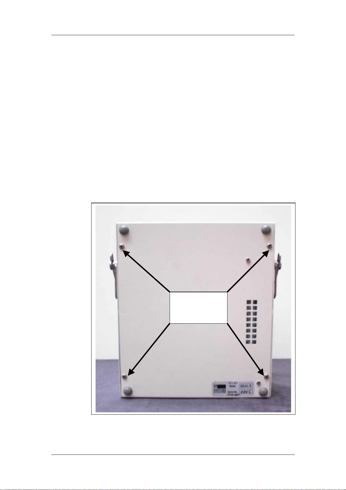
Maintenance
Servicing The EGM-4
Fuse
The EGM-4 circuitry is protected by a 1A (5x20mm) fuse. This is located in a black fuse
holder located at the back of the instrument (see
replacement, please ensure that the correct size and type of fuse is used.
It is very easy to determine if a fuse is good or bad. Usually, a bad fuse will be burned out
and visually obvious. The true test is to use an ohm m eter. Place one lead from the ohm
meter on one end of the fuse and the other lead on the opposite end of the fuse. If it reads 0,
you have a good fuse. Anything else, the fuse is bad and should be replaced.
The EGM-4 enclosure must be removed in order to service the following items:
• Infrared Source
• EPROM
• Zero Valve
• 12V Lead Acid Battery
• Air Sampling Pump
Remove These 4
Screws To Access
Internal EGM-4
Components
Back Of EGM-4
). If this requires
EGM-4 Operator's Manual – Version 1.00
- 40 -
Page 41
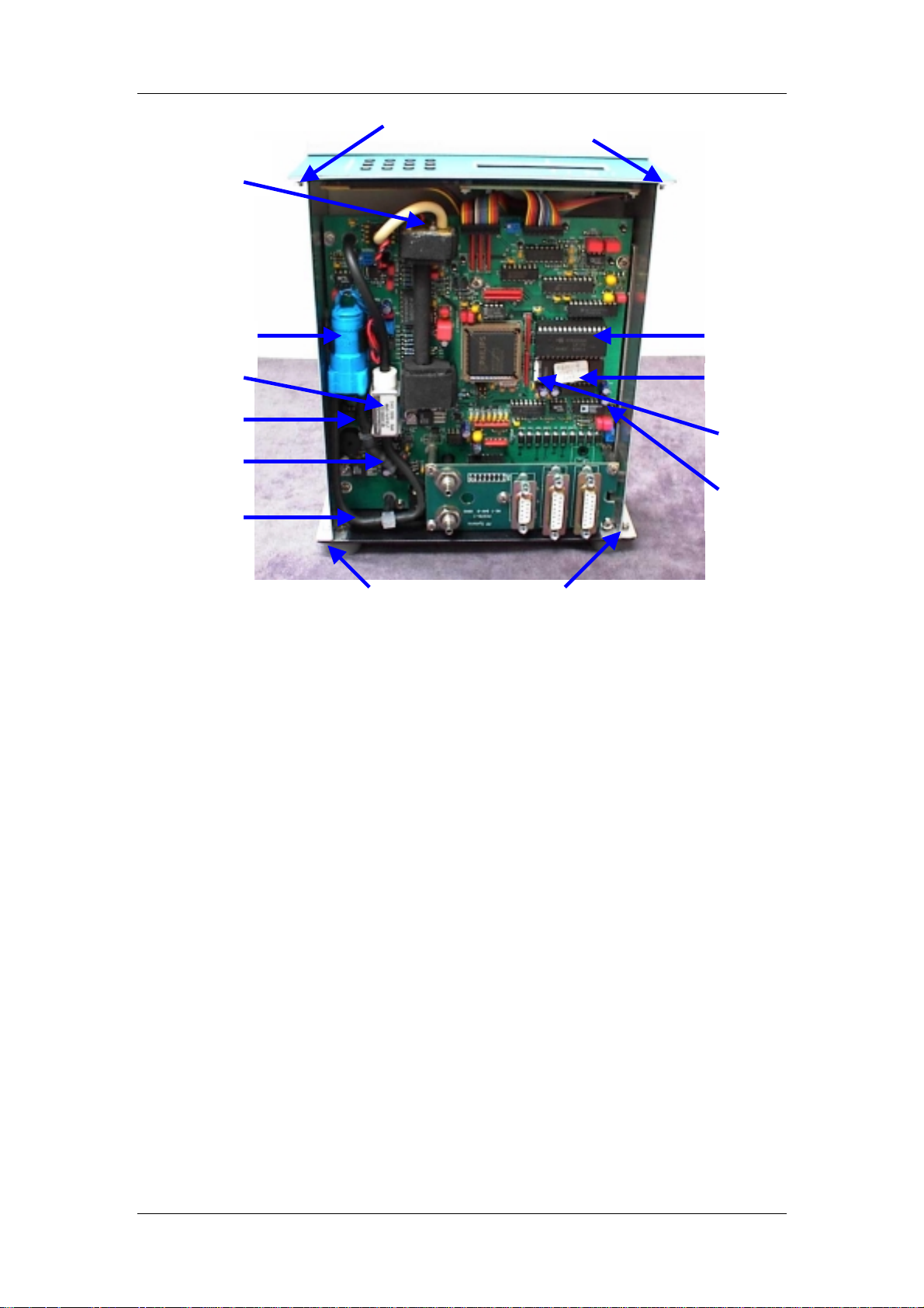
Maintenance
Air Sample Pump
CN6 (Alarm)
Infrared Source
Zero Valve
Air Out
Air In
Front Panel Retaining Nuts
Real Time Clock
EPROM
Notch On
EPROM
Current Output
(CN7, IOut)
Rear Panel Retaining Nuts/Screws
Inside The EGM-4
Infrared Source
The infrared source should last for many years and not require replacem ent. The obvious
sign of failure is that it is not flashing when the system is powered. However, it can be
replaced easily if required. To do so:
1. Disconnect the infrared source electrical connector located at CN13 by pulling up on it.
2. Rem ove the 4 s mall scr ews that secure the infrared s ource to the end of the sam ple cell
and remove it.
Fit the new infrared source to the end of the sam ple cell aligned to fit in the notch in the
3.
sample tube and secure it in plac e by the 4 small screws.
the bulb with your fingers and do not overtighten the scr ews.
4. Connect the new infrared source electrical connector to CN13 on PC075 circuit board.
The orientation does not matter.
Be very careful not to touch
EPROM
The firmware and f actory meas ured calibration f actor s f or the EGM-4 ar e stored on a mem ory
chip commonly referred to as an EPROM inside the instrument. This should never require
maintenance but it may need to be replaced if the system is upgraded.
The EPROM that is used in the EGM-4 m ust be protected fr om static electr icity. As a result,
there are several precautions that the cus tomer should take before removing EPROMS. The
risk of dam age can be minimized by earthing both the operator and the lab bench surface.
This can be done by covering the surface of the bench with a conductive material (e.g.
aluminium foil) that is electr ically connected to an earthing point suc h as a m etal water pipe or
tap. The operator should also be earthed using a wrist strap or by holding a wire that is
connected to the same earthed point. Please contact PP Systems for further information.
EGM-4 Operator's Manual – Version 1.00
- 41 -
Page 42

Maintenance
Once suitable earthing arrangem ents have been made, the EGM-4 enclosure can be opened
to gain access to the circuit board containing the EPROM. The position of the EPROM is
shown above.
Each EPROM is located in a specific orientation. Befor e starting to rem ove the chip, note the
position of the notch on the end of the chip relative to the rest of the instrument. Using a
small, flat screwdriver, gently pry the EPROM up until it is rem oved from its socket. W hen
fitting the new EPROM to the socket, be caref ul not to bend any pins. Place the EPROM in
the socket (noting the notch on one end of the EPRO M) and gently press down to secure in
place.
Very Important.
Error! Reference source not found.
After replacing the EPROM, you should reinitialize the instrument (See
).
ZERO Valve
If it is suspected that the ZERO valve is not functioning pr operly, we recomm end r eturning the
EGM-4 to our f actory for repair as this item is soldered directly to the PC075 circuit board.
Contact PP Systems (see
PP Systems’ Contact Information
).
12V Lead Acid Battery
The 12V 2.0 Ah s ealed, rechargeable, lead acid battery should last for sever al years as long
as it is properly maintained. Based on manufacturer’s data, the battery is non-spillable
(qualified to non-spillable UN2800 standards) and can be used in any orientation. It has a
float design life of 5 years. It s hould be c hecked periodically to ensure that it takes up charge.
Measuring the voltage across the term inals of the battery after it has been char ged overnight
can assess this.
If the battery is not fully charged after 12 hours, first c heck that the 1A fuse is ok. This fuse
protects the charging circuit and if blown, the internal battery will not take a charge.
Please Note.
The internal 12V battery should always be fully charged before long-term
storage. If it is stored in a low or discharged state, it is possible that it will become deepdischarged. If this occur s, the charge capacity of the battery is permanently reduced and will
require replacement.
Battery Specification
Manufacturer Yuasa
Type NP2-12
Voltage 12V
Nominal Capacity
@ 20 hr.rate (Ah)
Terminals Faston Tab 0.187”
Housing ABS Resin
Dimensions 3.50” x 5.91” x .79”
Weight 1.54 Lbs.
2.0 Ah
EGM-4 Operator's Manual – Version 1.00
- 42 -
Page 43
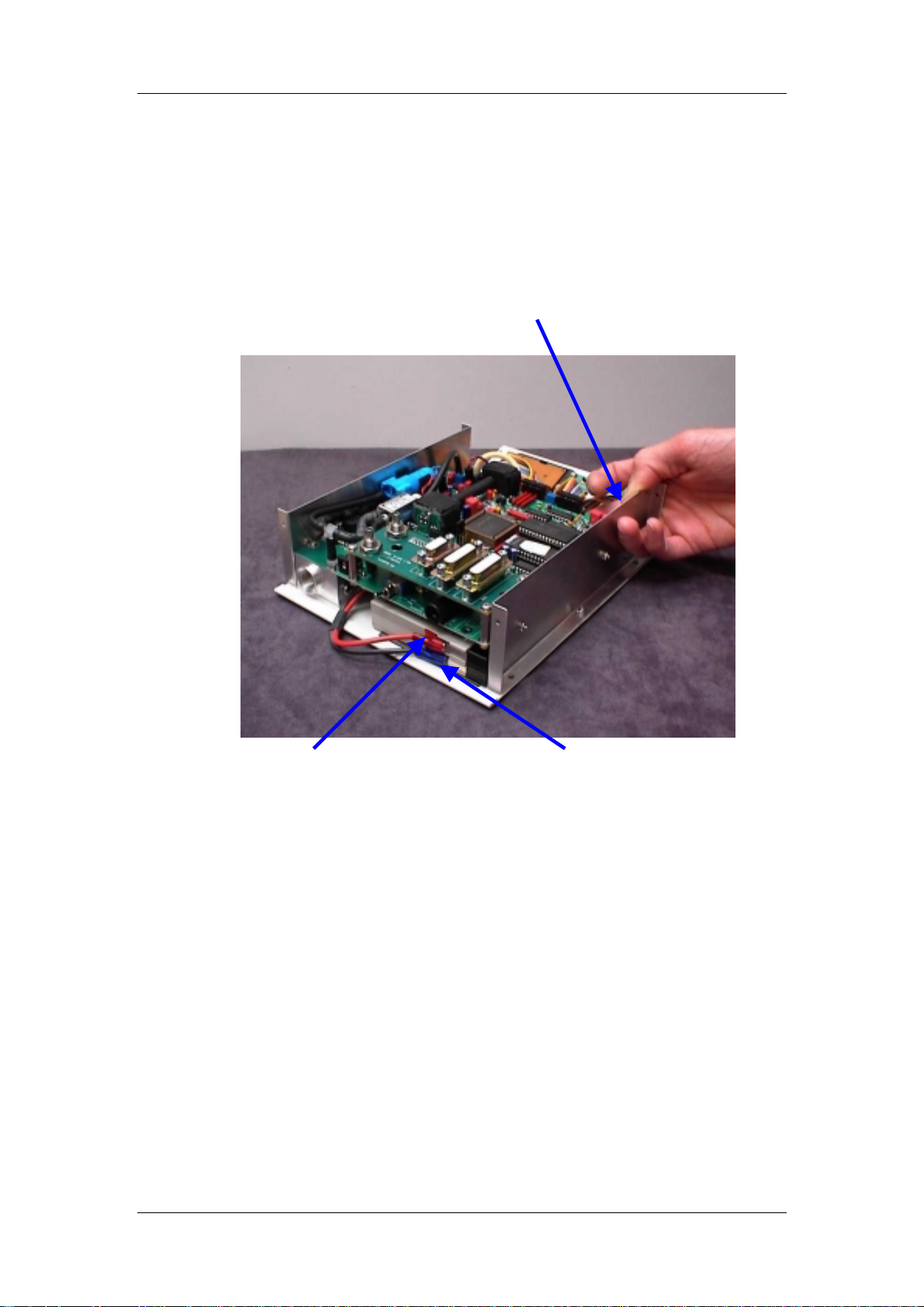
Maintenance
Removing The 12V Battery
The front panel may need to be removed to slide the battery out of its com partment if it is
stuck. W hen removing the battery, first ensur e that the power to the EGM-4 is turned off.
Next, remove the red (positive) and blue (negative) charger leads from the battery.
Slide the new battery into the battery compartment, connect the charger leads correctly (Red
= Positive, Black = Negative) and refit the enclosure.
Red (Positive) Charger Lead Blue (Negative) Charger Lead
If the battery is stuck, r emove the front panel
retaining nuts, gently pull panel forwards, and
push back of battery through hole provided.
Air Sampling Pump
The EGM-4 is fitted with a sealed, rotary vane pumps to sam ple the reference air. Rotary
vane pump components wear with prolonged use and m aterial from the vanes m ay build up
within the pumps. T his can eventually reduce the pumping efficienc y or even cause them to
seize. The normal signs of a bad pump are as follows:
1.
2.
A worn pump usually sounds rough or vibrates.
Noise.
Temperature.
The outer casing is hot when touched with your fingers.
EGM-4 Operator's Manual – Version 1.00
- 43 -
Page 44
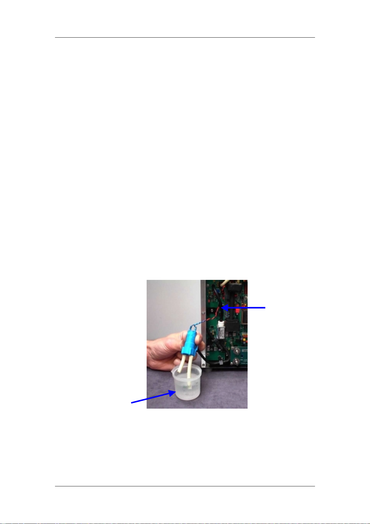
Maintenance
Replacing The Air Sampling Pump
It is very easy to replace a bad air sampling pump. First, tr ace the electr ical connec tion to the
pump and disconnect the 2-pin connector from the terminal on the EGM-4 circuit board.
Secondly, the electrical connector is rem oved by gently bending back the connector lock and
sliding out the connector.
correct re-fitting of the pump
Please note the orientation of the red and black wire for
. The pump itself is secured in position by the gas tubing
connections. Finally, remove the tubing from the inlet and outlet ports on the pump and lift
out.
Fit the new pump making sure that:
1. The flat back part of the pump sits flush on its manifold.
2. Connec t the inlet tubing to the inlet port and the outlet tubing to the outlet port on the
pump.
3. Finally, the 2-pin electrical connector s hould be reconnected in the same orientation.
The two notches on the connector latch with the corresponding lock.
Cleaning The Air Sampling Pump
During prolonged operation, the vanes inside the pump will wear and deposit material inside
the pump. It is sensible to clean the pump by periodically flushing it with with isopropyl
alcohol. The following procedure can be adopted:
1. Connect the pump to a 6-12V source and fit a 30mm tube to the pump inlet.
(i.e. the EGM-4 can be used to supply power via the pump electrical connector.
however, essential that the flu shing is p erformed ou tside of the instrument to avoi d
spillage into it
).
2. Hold the pump above a beaker of isopropyl alcohol and dip the tube into the alcohol (See
below). Run the pump to draw alcohol through it. A small roll of cotton wool in the inlet
pipe can act as a filter for the re-circulating alcohol.
It is,
Pump
Electrical
Connector
Alcohol
If the pump is seized, it may be freed by tapping it on the bench or by reversing the
voltage to run it backwards.
3. Run alcohol through the pum p for a m inute or two to ensure that any material is removed.
When f inished, run the pump in air for at least 15 m inutes to allow any residual alcohol to
eVapourate. Ideally, let the pumps dry outside of the EGM-4 overnight. If the pum ps are
reconnected prematurely, the absorber chemical (soda lime) will be exhausted quicker
than usual.
EGM-4 Operator's Manual – Version 1.00
- 44 -
Page 45
Maintenance
In-Line Hydrophobic Filter
If the In-Line Hydrophobic Filter is used with the EGM-4, it is very important to periodically
inspect the internal filter and “O” Ring. To check the internal filter:
1. Open the filter holder.
2. Remove internal “O” Ring using a fine screwdriver or similar tool.
3. Remove the internal 3 m icr on, hydrophobic filter and inspect f or dir t, dust or m ois ture.
If there is any sign of dirt, dust or moisture, replace the filter.
If a new filter is f itted, place the filter in the holder, place a slight s mear of silic one grease on
the “O” ring and fit the “O” ring inside the holder to s ecure the filter in place. Refit the other
end of the holder and tighten.
Important Note
The “O” r ing must always be used with the in-line holder to ensure leak tight seal. Tak e care
not to apply too much silicone grease to the “O” ring as this could contaminate the filter.
“O” Ring
3 micron, hydrophobic
filter
EGM-4 Operator's Manual – Version 1.00
- 45 -
 Loading...