

Page 1

Powerware 9390 UPS Sidecar
®
Installation and Operation Manual
For use with 40–80 kVA and 100–160 kVA UPS Models
Page 2

IMPORTANT SAFETY INSTRUCTIONS
SAVE THESE INSTRUCTIONS
This manual contains important instructions that you should follow during installation and maintenance of the UPS and
batteries. Please read all instructions before operating the equipment and save this manual for future reference.
Consignes de sécurité
CONSIGNES DE SÉCURITÉ IMPORTANTES
CONSERVER CES INSTRUCTIONS
CE MANUEL CONTIENT DES CONSIGNES DE SÉCURITÉ IMPORTANTES
Eaton and Powerware are registered trademarks of Eaton Corporation or its subsidiaries and affiliates.
ECopyright 2004–2007 Eaton Corporation, Raleigh, NC, USA. All rights reserved. No part of this document may be reproduced in any way without
the express written approval of Eaton Corporation.
Page 3

Table of Contents
1 Introduction 1-1...........................................................................
1.1 Configurations 1-1........................................................................................
1.2 Using This Manual 1-4.....................................................................................
1.3 Conventions Used in This Manual 1-5..........................................................................
1.4 Safety Warnings 1-6.......................................................................................
1.5 For More Information 1-6...................................................................................
1.6 Getting Help 1-7..........................................................................................
Section I – Installation
2 Installing the UPS Sidecar 2-1...............................................................
2.1 Installation Plan and Unpacking 2-1............................................................................
2.2 Preliminary Installation Information 2-1.........................................................................
2.3 UPS Sidecar Installation – Maintenance Bypass Configuration 2-1......................................................
2.3.1 Installing the UPS Cabinet with UPS Sidecar 2-1..............................................................
2.3.2 Installing Maintenance Bypass Power Wiring 2-1.............................................................
2.4 UPS Sidecar Installation – Parallel Redundant Configuration 2-4.......................................................
2.4.1 Line-up-and-Match Parallel Redundant Installation 2-4..........................................................
2.4.2 Installing Line-up-and-Match Parallel Redundant Power Wiring 2-7.................................................
2.4.3 Standalone Parallel Redundant Installation 2-8...............................................................
2.4.4 Installing Standalone Parallel Redundant Power Wiring 2-9......................................................
2.4.5 Installing UPS Sidecar TB1 Interface Connections 2-10...........................................................
2.5 Initial Startup 2-10.........................................................................................
2.6 Completing the Installation Checklist 2-10........................................................................
Section II – Operation
3 Understanding Operation 3-1................................................................
3.1 Maintenance Bypass Configuration 3-1.........................................................................
3.1.1 UPS Mode 3-1......................................................................................
3.1.2 Maintenance Bypass Mode with UPS Sidecar 3-2.............................................................
3.2 Parallel Redundant Configuration 3-2...........................................................................
4 UPS Sidecar Features, Controls, and Operation 4-1...............................................
4.1 UPS Sidecar Standard Features 4-1............................................................................
4.1.1 Maintenance Bypass Configuration 4-1.....................................................................
4.1.2 Parallel Redundant Configuration 4-1......................................................................
4.1.3 Customer Interface 4-1................................................................................
4.1.4 Installation Features 4-1...............................................................................
4.1.5 Expansion 4-1.......................................................................................
4.2 Options 4-1.............................................................................................
4.2.1 Bypass Input Breaker (BIB) 4-1...........................................................................
4.2.2 Rectifier Input Breaker (RIB) 4-2..........................................................................
4.2.3 System Load Breaker (SLB) 4-2...........................................................................
4.3 Symbols 4-2.............................................................................................
4.4 UPS Sidecar Controls 4-3...................................................................................
EATON Powerware®9390 UPS Sidecar Installation and Operation Manual S 164201586 Rev E www.powerware.com
i
Page 4

TABLE OF CONTENTS
4.5 UPS Sidecar Operation – Maintenance Bypass Configuration 4-13.......................................................
4.5.1 Using the UPS when a UPS Sidecar is Installed 4-13............................................................
4.5.2 Transferring the UPS to Maintenance Bypass 4-13..............................................................
4.5.3 Transferring the UPS from Maintenance Bypass 4-14............................................................
4.6 UPS Sidecar Operation – Parallel Redundant Configuration 4-15........................................................
4.7 Maintaining the UPS Sidecar 4-15..............................................................................
4.8 Product Specifications 4-15...................................................................................
5 Warranty 5-1.............................................................................
6 Installation Information A-1..................................................................
ii
EATON Powerware®9390 UPS Sidecar Installation and Operation Manual S 164201586 Rev E www.powerware.com
Page 5

List of Figures
Figure 1-1. Powerware 9390 UPS (40–80 kVA) with UPS Sidecar 1-2..................................................
Figure 1-2. Powerware 9390 UPS (100–160 kVA) with UPS Sidecar 1-3.................................................
Figure 2-1. 80 kVA UPS with UPS Sidecar 2-3...................................................................
Figure 2-2. Typical Line-up-and-Match Parallel Redundant System (80 kVA System Shown) 2-4................................
Figure 2-3. UPM 1 to UPM 2 Joining Brackets 2-6................................................................
Figure 2-4. Typical Standalone Parallel Redundant System (80 kVA System Shown) 2-8.....................................
Figure 3-1. Path of Current Through the UPS Sidecar in UPS Mode 3-1.................................................
Figure 3-2. Path of Current Through the UPS Sidecar in Maintenance Bypass Mode 3-2.....................................
Figure 4-1. UPS Sidecar Controls (Bypass) – 40/20, 40/30, 40/40 kVA, 480/480V with MBP and MIS 4-4.........................
Figure 4-2. UPS Sidecar Controls (Bypass) – 40/20, 40/30, 40/40 kVA, 480/480V with Optional BIB and RIB 4-5....................
Figure 4-3. UPS Sidecar Controls (Bypass) – 40/20, 40/30, 40/40 kVA, 208/208V and 80/40, 80/50, 80/60,
80/80 kVA and 120/100 and 120/120 kVA, 480/480V with MBP and MIS 4-6.........................................
Figure 4-4. UPS Sidecar Controls (Bypass) – 40/20, 40/30, 40/40 kVA, 208/208V and 80/40, 80/50, 80/60,
80/80 kVA and 120/100 and 120/120 kVA, 480/480V with Optional BIB and RIB 4-7....................................
Figure 4-5. UPS Sidecar Controls (Bypass) – 80/40, 80/50, 80/60, 80/80 kVA, 208/208V and
160/100, 160/120, and 160/160 kVA, 480/480V with MBP and MIS 4-8.............................................
Figure 4-6. UPS Sidecar Controls (Bypass) – 80/40, 80/50, 80/60, 80/80 kVA, 208/208V and
160/100, 160/120, and 160/160 kVA, 480/480V with Optional BIB and RIB 4-9........................................
Figure 4-7. UPS Sidecar Controls (Parallel Redundant) – 40/20, 40/30, 40/40 kVA, 480/480V with MOBs and Optional SLB 4-10.........
Figure 4-8. UPS Sidecar Controls (Parallel Redundant) – 40/20, 40/30, 40/40 kVA, 208/208V and
80/40, 80/50, 80/60, 80/80 kVA and 120/100, and 120/120 kVA, 480/480V with MOBs and Optional SLB 4-11..................
Figure 4-9. UPS Sidecar Controls (Parallel Redundant) – 80/40, 80/50, 80/60, 80/80 kVA, 208/208V
and 160/100, 160/120, and 160/160 kVA, 480/480V with MOBs and Optional SLB 4-12..................................
EATON Powerware®9390 UPS Sidecar Installation and Operation Manual S 164201586 Rev E www.powerware.com
iii
Page 6

LIST OF FIGURES
This page intentionally left blank.
iv
EATON Powerware®9390 UPS Sidecar Installation and Operation Manual S 164201586 Rev E www.powerware.com
Page 7

Chapter 1 Introduction
Figure
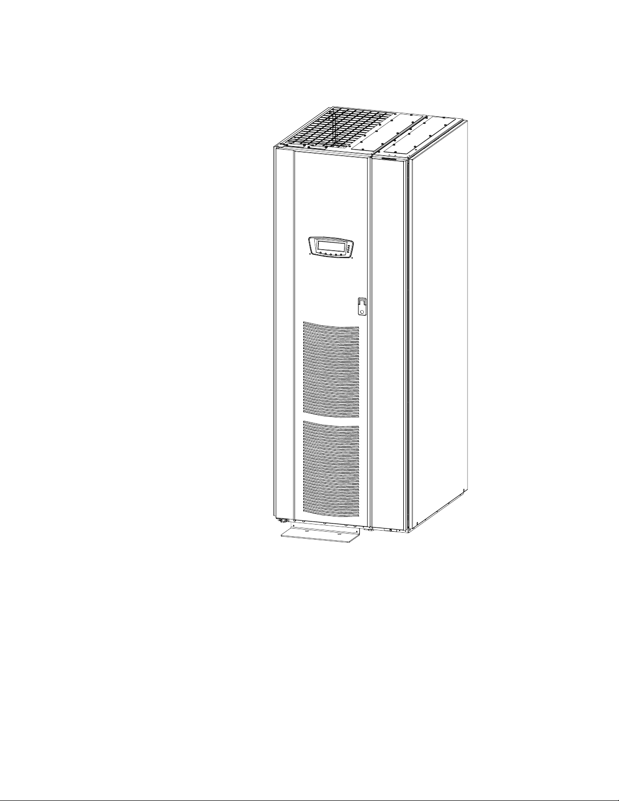
The Eaton®Powerware®9390 UPS Sidecar is designed for use with the Powerware
9390 80 kVA 208/208V and 480/480V and 160 kVA 480/480V three-phase
uninterruptible power systems (UPSs). The UPS Sidecar provides maintenance
bypass or tie cabinet functions with the following custom configurable features,
enabling adaptation and expansion without costly electrical rework:
S Maintenance Bypass Configuration – Maintenance Bypass (MBP) and Maintenance
Isolation (MIS) breakers enable power to completely bypass the UPS power
module. The UPS module can then be safely serviced or replaced, without
interrupting power to critical systems. An optional Bypass Input Breaker (BIB) and
Rectifier Input Breaker (RIB) provide a single wiring point input to the UPS and a
convenient method for removing power from the UPS when using the
maintenance bypass to supply the load.
S Parallel Redundant Configuration – Module Output Breakers (MOBs) 1 and 2
enable two UPS modules to be paralleled together for redundancy. An optional
System Load Breaker (SLB) provides output control to the critical load for the
whole system.
The UPS Sidecar is attached to and directly integrated with the UPS cabinet and has
safety shields behind the removable front panel for hazardous voltage protection. The
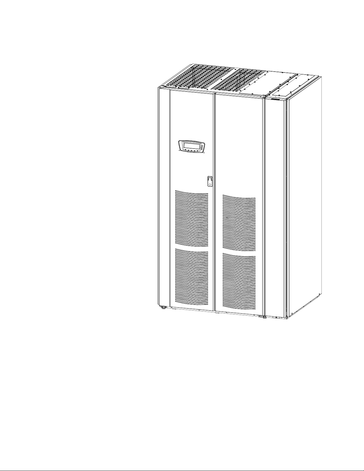
UPS Sidecar matches the UPS cabinet in style and color. Figure 1-1 shows the
Powerware 9390 UPS (40–80 kVA) with the UPS Sidecar and Figure 1-2 shows the
Powerware 9390 UPS (100–160 kVA) with the UPS Sidecar.
1.1 Configurations
The following UPS Sidecar configurations are possible:
S UPS Sidecar with MBP and MIS
S UPS Sidecar with MB P, MIS, and BIB
S UPS Sidecar with MBP, MIS, BIB, and RIB
S UPS Sidecar with M OB 1 and MOB 2
S UPS Sidecar with MOB 1, MOB 2, and SLB
EATON Powerware®9390 UPS Sidecar Installation and Operation Manual S 164201586 Rev E www.powerware.com
1-1
Page 8
INTRODUCTION
1-2
Figure 1-1. Powerware 9390 UPS (40–80 kVA) with UPS Sidecar
EATON Powerware®9390 UPS Sidecar Installation and Operation Manual S 164201586 Rev E www.powerware.com
Page 9
INTRODUCTION
Figure 1-2. Powerware 9390 UPS (100–160 kVA) with UPS Sidecar
EATON Powerware®9390 UPS Sidecar Installation and Operation Manual S 164201586 Rev E www.powerware.com
1-3
Page 10

INTRODUCTION
1.2 Using This Manual
This manual describes how to install and operate the Powerware 9390 UPS Sidecar.
Read and understand the procedures described in this manual to ensure trouble-free
installation and operation.
The information in this manual is divided into the sections and chapters listed. At a
minimum, Chapters 1, 2, and 4 should be examined. Read through each procedure
before beginning the procedure.
S Chapter 1, “Introduction” – provides a brief description of the UPS Sidecar, a
description of the content of each chapter, text conventions used in the m anual,
safety warnings, and reference information.
Section I, Installation
S Chapter 2, “Installing the UPS Sidecar” – describes how to install and wire the UPS
Sidecar.
Section II, Operation
S Chapter 3, “Understanding Operation” – provides information on how the UPS Sidecar
works.
S Chapter 4, “UPS Sidecar Features, Controls, and Operation” – describes the standard and
optional UPS Sidecar features, the UPS Sidecar controls, and how to use the UPS
Sidecar.
S Appendix A, “Installation Information” – contains important information on wiring
requirements and recommendations, and important diagrams of the cabinets’
mechanical details and electrical access.
S Warranty – provides the Eaton warranty for this product.
1-4
EATON Powerware®9390 UPS Sidecar Installation and Operation Manual S 164201586 Rev E www.powerware.com
Page 11

1.3 Conventions Used in This Manual
This manual uses these type conventions:
S Bold type highlights important concepts in discussions, key terms in procedures,
and menu options.
S Italic type highlights notes and new terms where they are defined.
S Screen type represents information that appears on the screen or LCD.
Icon Description
Information notes call attention to important features or instructions.
In this manual, the term UPS refers only to the UPS cabinet and its internal elements.
The term UPS system refers to the entire power protection system – the UPS
cabinet, the battery cabinet, the UPS Sidecar, and options or accessories installed.
The term line-up-and-match refers to cabinets that are physically attached to the UPS,
and the wiring between them is internal. The term standalone refers to cabinets that
are not physically attached to the UPS, and are wired with external customer-supplied
wiring.
INTRODUCTION
EATON Powerware®9390 UPS Sidecar Installation and Operation Manual S 164201586 Rev E www.powerware.com
1-5
Page 12

INTRODUCTION
1.4 Safety Warnings
IMPORTANT SAFETY INSTRUCTIONS
SAVE THESE INSTRUCTIONS
This manual contains important instructions that should be followed during installation and maintenance of
the UPS Sidecar. Please read all instructions before operating the equipment and save this manual for future
reference.
The UPS Sidecar is designed for industrial or computer room applications, and contains safety shields behind
the front panel. However, the UPS system is a sophisticated power system and should be handled with
appropriate care.
DANGER
This UPS system contains LETHAL VOLTAGES. All repairs and service should be performed by
AUTHORIZED SERVICE PERSONNEL ONLY. There are NO USER SERVICEABLE PARTS inside the UPS.
WARNING
S The UPS system contains its own energy source (batteries). The output terminals may carry live voltage
even when the UPS is disconnected from an AC source.
S To reduce the risk of fire or electric shock, install this UPS Sidecar in a temperature and humidity
controlled, indoor environment, free of conductive contaminants. Ambient temperature must not exceed
40°C (104°F). Do not operate near water or excessive humidity (95% maximum). The system is not
intended for outdoor use.
S Ensure all power is disconnected before performing installation or service.
1.5 For More Information
CAUTION
S Never dispose of batteries in a fire. Batteries may explode when exposed to flame.
S Keep the UPS Sidecar front panel installed to protect personnel from dangerous voltages inside the unit.
S Do not operate the UPS system close to gas or electric heat sources.
S The operating environment should be maintained within the parameters stated in this manual.
S Keep surroundings uncluttered, clean, and free from excess moisture.
S Observe all DANGER, CAUTION, and WARNING notices affixed to the inside and outside of the
equipment.
Refer to the Powerware 9390 UPS (40–80 kVA) Installation and Operation Manual or the
Powerware 9390 UPS (100–160 kVA) Installation and Operation Manual for the following
additional information:
S UPS cabinet, optional components, and accessory installation instructions,
including site preparation, planning for installation, and wiring and safety
information. Detailed illustrations of cabinets and optional accessories with
dimensional and connection point drawings are provided.
S UPS operation, including UPS cabinet controls, functions of the UPS, standard
features and optional accessories, procedures for starting and stopping the UPS,
and information about maintenance and responding to system events.
S Communication capabilities of the UPS system.
1-6
Visit www.powerware.com or contact your Eaton service representative for
information on how to obtain copies of these manuals.
EATON Powerware®9390 UPS Sidecar Installation and Operation Manual S 164201586 Rev E www.powerware.com
Page 13

1.6 Getting Help
INTRODUCTION
If help is needed with any of the following:
S Scheduling initial startup
S Regional locations and telephone numbers
S A question about any of the information in this manual
S A question this manual does not answer
Please call the Eaton Help Desk for Powerware products at:
United States:
Canada: 1-800-461-9166 ext 260
All other countries: Call your local service representative
1-800-843-9433 or 1-919-870-3028
EATON Powerware®9390 UPS Sidecar Installation and Operation Manual S 164201586 Rev E www.powerware.com
1-7
Page 14

INTRODUCTION
This page intentionally left blank.
1-8
EATON Powerware®9390 UPS Sidecar Installation and Operation Manual S 164201586 Rev E www.powerware.com
Page 15

Section I
Installation
EATON Powerware®9390 UPS Sidecar Installation and Operation Manual S 164201586 Rev E www.powerware.com
1-1
Page 16

1-2
EATON Powerware®9390 UPS Sidecar Installation and Operation Manual S 164201586 Rev E www.powerware.com
Page 17

Chapter 2 Installing the UPS Sidecar
Figure
2.1 Installation Plan and Unpacking
Refer to the applicable Powerware 9390 installation and operation manual, listed in
paragraph 1.5, for installation planning and unpacking.
2.2 Preliminary Installation Information
WARNING
Installation should be performed only by qualified personnel.
Refer to the following while installing the UPS Sidecar:
S Appendix A contains installation drawings and additional installation notes.
S Dimensions are in millimeters and inches.
S The conduit landing plates are to be removed to add conduit landing holes, or
remove knockouts, as required. Plate material is 16 gauge steel (1.5 mm/0.060”
thick).
S Refer to the applicable Powerware 9390 installation and operation manual, listed in
paragraph 1.5, for UPS cabinet installation, wiring information, and conduit and
terminal locations.
2.3 UPS Sidecar Installation – Maintenance Bypass Configuration
2.3.1 Installing the UPS Cabinet with UPS Sidecar
The UPS Sidecar is a factory-installed integral part of the standard UPS cabinet. Refer
to the applicable Powerware 9390 installation and operation manual, listed in
paragraph 1.5, for UPS cabinet installation.
2.3.2 Installing Maintenance Bypass Power Wiring
NOTE Remove the UPS Sidecar top or bottom conduit landing plate to drill or punch conduit holes, or
remove knockouts (see Drawing 164201546-5 starting on page A-27).
NOTE Refer to the applicable Powerware 9390 installation and operation manual, listed in paragraph 1.5,
for UPS cabinet wiring information and conduit and terminal locations.
NOTE If input or output neutrals are required, wire the neutrals to the neutral terminals located inside the
UPS cabinet.
NOTE Wire grounds to the ground terminals located inside the UPS cabinet.
1. Verify the UPS system is turned off and all power sources are removed. Refer to
the applicable Powerware 9390 installation and operation manual, listed in
paragraph 1.5, for shutdown instructions.
2. If not already removed, remove the screw securing the bottom of the UPS
Sidecar front panel (see Figure 2-1). Lift up the panel and remove.
EATON Powerware®9390 UPS Sidecar Installation and Operation Manual S 164201586 Rev E www.powerware.com
2-1
Page 18

INSTALLING THE UPS SIDECAR
3. If not already removed, remove the screws securing the internal safety shield
panel and remove the panel to gain access to the terminals.
NOTE If a Bypass Input Breaker is not installed, a minimum of two separate feeds with upstream feeder
breakers, or one feed with two upstream feeder breakers, must be provided: one for the UPS and one for the
UPS Sidecar bypass input. DO NOT use one feed or a single-feeder breaker to supply both the UPS and
Sidecar.
4. If wiring a single-feed system with or without a Rectifier Input Breaker, continue
to Step 5; if wiring a dual-feed system with an RIB, proceed to Step 8.
5. Route the bypass input cables to the UPS Sidecar bypass terminals. See Drawing
164201546-6, starting on page A-30, for UPS Sidecar wiring access information
and terminal locations.
6. Connect phase A, B, and C bypass input power wiring from the source to the
bypass terminals on the UPS Sidecar.
7. Proceed to Step 12.
8. Disconnect the single-feed jumpers between BIB 1, 3, 5 terminals and RIB 1, 3,
5 terminals.
9. Route the bypass and rectifier input cables to the UPS Sidecar bypass and
rectifier input terminals. See Drawing 164201546-6, starting on page A-30, for
UPS Sidecar wiring access information and terminal locations.
10. Connect phase A, B, and C bypass input power wiring from the source to the
bypass terminals on the UPS Sidecar.
11. Connect phase A, B, and C power wiring from the source to the UPS rectifier
input terminals on the UPS Sidecar.
12. Route the output cables to the UPS Sidecar output terminals. See Drawing
164201546-6, starting on page A-30, for UPS Sidecar wiring access information
and terminal locations.
13. Connect phase A, B, and C, and Neutral power wiring from the UPS Sidecar
output terminals to the critical load.
14. After wiring the UPS system to the facility power and critical load, be sure to
ground the system according to local and/or national electrical wiring codes.
15. When all wiring is complete, reinstall the internal safety shield panels removed in
previous steps.
16. Reinstall the UPS Sidecar front panel and secure with the screw at the bottom of
the panel.
2-2
EATON Powerware®9390 UPS Sidecar Installation and Operation Manual S 164201586 Rev E www.powerware.com
Page 19
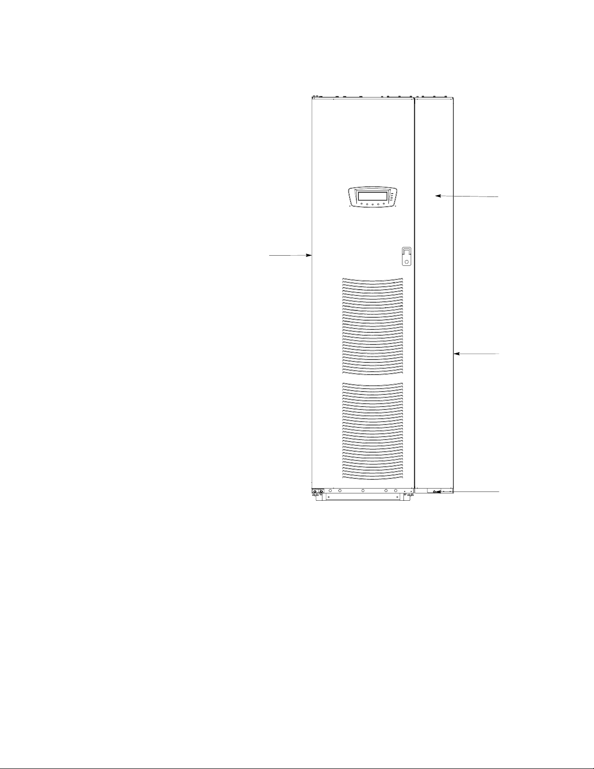
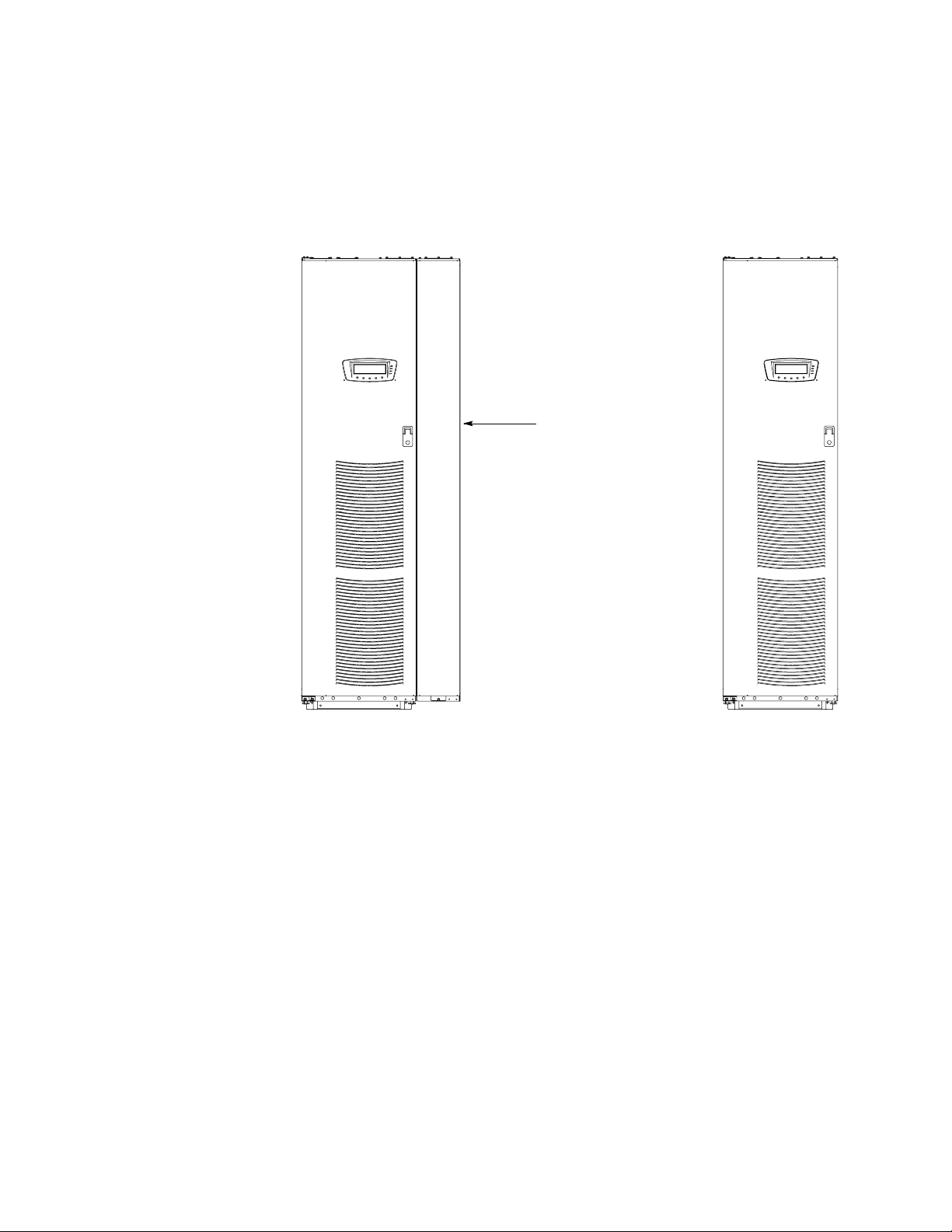
UPS Cabinet
INSTALLING THE UPS SIDECAR
Front Panel
Figure 2-1. 80 kVA UPS with UPS Sidecar
UPS Sidecar
Front Panel
Attaching Screw
EATON Powerware®9390 UPS Sidecar Installation and Operation Manual S 164201586 Rev E www.powerware.com
2-3
Page 20
INSTALLING THE UPS SIDECAR
2.4 UPS Sidecar Installation – Parallel Redundant Configuration
The method used to install the UPS Sidecar depends on the type of installation being
undertaken. The UPS Sidecar can be installed as a line-up-and-match or standalone
system.
S To install a line-up-and-match parallel redundant system, continue to
paragraph 2.4.1.
S To install a standalone parallel redundant system, proceed to paragraph 2.4.3.
2.4.1 Line-up-and-Match Parallel Redundant Installation
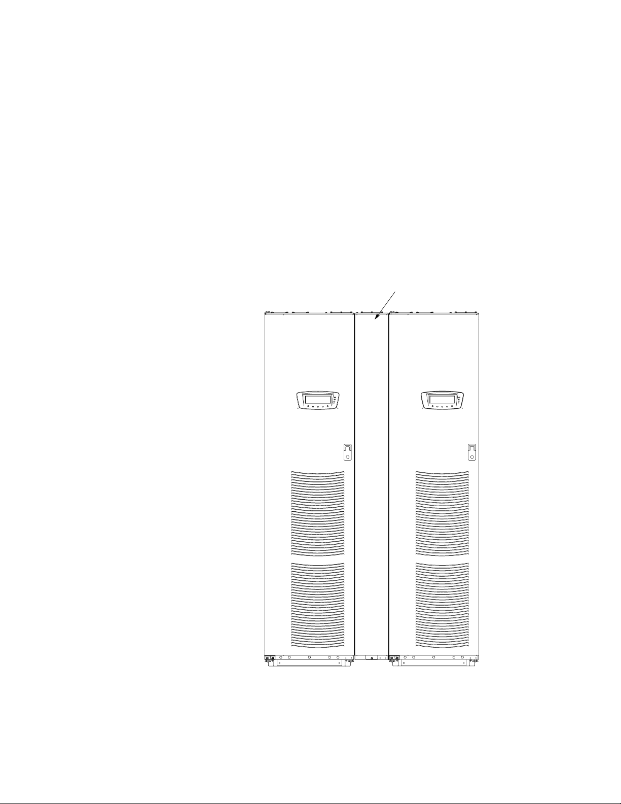
Use this procedure to install uninterruptible power module (UPM) 2 adjacent to
UPM 1 (see Figure 2-2). UPM 1 has the Sidecar installed. The UPS Sidecar is a
factory-installed integral part of the standard UPS cabinet.
Sidecar
2-4
UPM 1 UPM 2
Figure 2-2. Typical Line-up-and-Match Parallel Redundant System (80 kVA System Shown)
EATON Powerware®9390 UPS Sidecar Installation and Operation Manual S 164201586 Rev E www.powerware.com
Page 21

INSTALLING THE UPS SIDECAR
1. Verify that the UPM 1 is properly installed and secured. Refer to the applicable
Powerware 9390 installation and operation manual, listed in paragraph 1.5, for
installation instructions.
2. On UPM 1, if not already removed, remove the screw securing the bottom of the
UPS Sidecar front panel (see Figure 2-1 on page 2-3). Lift up the panel and
remove.
3. On UPM 1, if not already removed, remove the screws securing the internal
safety shield panel and remove the panel to gain access to the terminals.
4. Remove the field kit from the bottom of the UPS Sidecar and retain for later use.
5. Roll UPM 2 to an area near the right-hand side of UPM 1.
6. Open or remove doors, internal safety shield panels, and cosmetic covers, as
required, according to the instructions contained in the applicable Powerware
9390 installation and operation manual, listed in paragraph 1.5.
7. Remove the knockouts, as required, on the bottom r ight side inside panel of the
UPM 1 UPS Sidecar (see Drawing 164201546-5, sheet 3 of 3, on page A-29).
8. Remove the knockouts on the bottom left side inside panel of UPM 2. Refer to
the applicable Powerware 9390 installation and operation manual, listed in
paragraph 1.5, for the location of the knockout plug.
9. Install the nylon grommets from the field kit around the holes left after removing
the knockouts.
10. Push UPM 2 toward the right side of UPM 1 until the doors are flush with each
other.
11. If not already installed, mount the hanger brackets to the top right side of the
UPM 2 using M4 screws (see Drawing 164201546-5, sheet 3 of 3, on
page A-29).
12. If not already installed, hang the side panel on the hanger brackets and align with
the front and rear of the UPM 2.
13. Secure UPM 2 in position. Refer to the applicable Powerware 9390 installation
and operation manual, listed in paragraph 1.5, for installation instructions.
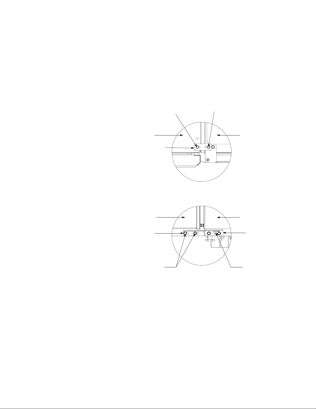
NOTE Two cabinet joining brackets are provided in the field kit for securing each cabinet at the top and
bottom. A small flat bracket joins the top of the cabinets and a larger angle bracket joins the cabinets at the
bottom. The small flat bracket is attached to the cabinet tops first.
14. Remove the left-hand screw from t he top door hinge on UPM 2.
15. Locate the small flat bracket, four washers, and M4 screw from the field kit.
Align the holes in the small flat bracket over the hole in the top of the UPS
Sidecar attached to UPM 1 and the door hinge screw hole on UPM 2. Use the
four washers between the bracket and the top of the UPS Sidecar to match the
thickness of hinge on UPM 2. Secure the bracket to the UPS Sidecar using the
M4 screw, and to the hinge on UPM 2 using the screw removed in Step 14 (see
Figure 2-3).
16. Locate the large angle bracket, M4 screws, and large nut from the field kit. Place
one end of the bracket over the bolt on the bottom side of the lower left-hand
hinge on UPM 2, and loosely secure the bracket to the hinge with the large nut
(see Figure 2 -3).
EATON Powerware®9390 UPS Sidecar Installation and Operation Manual S 164201586 Rev E www.powerware.com
2-5
Page 22
INSTALLING THE UPS SIDECAR
17. Align the holes in the other end of the bracket with the holes in the bottom
right-hand side of the UPS Sidecar attached to UPM 1 (see Figure 2-3). Secure
the bracket with M4 screws from the field kit.
18. Secure the large nut on the UPM 2 hinge.
19. Continue to paragraph 2.4.2.
M4 Screw
and Four Washers
from Kit
UPM 1 UPS Sidecar UPM 2
Small Flat Bracket from Kit
Top View with Small Bracket
UPM 1 UPS Sidecar
Large Angle Bracket from Kit
Existing
Screw
UPM 2
Existing Hinge
2-6
M4 Screws from Kit
Front View with Large Angle Bracket
Figure 2-3. UPM 1 to UPM 2 Joining Brackets
EATON Powerware®9390 UPS Sidecar Installation and Operation Manual S 164201586 Rev E www.powerware.com
Nut from Kit
Page 23

INSTALLING THE UPS SIDECAR
2.4.2 Installing Line-up-and-Match Parallel Redundant Power Wiring
NOTE Remove the UPS Sidecar top or bottom conduit landing plate to drill or punch conduit holes, or
remove knockouts (see Drawing 164201546-5 starting on page A-27).
NOTE Refer to the applicable Powerware 9390 installation and operation manual, listed in paragraph 1.5,
for UPS cabinet wiring information and conduit and terminal locations.
CAUTION
Specified wiring and the MOB and SLB breakers for the UPS Sidecar are rated for parallel redundant service
only. DO NOT use as a parallel capacity system.
1. Verify the UPS system is turned off and all power sources are removed. Refer to
the applicable Powerware 9390 installation and operation manual, listed in
paragraph 1.5, for shutdown instructions.
2. If not already removed, remove the screw securing the bottom of the UPS
Sidecar front panel (see Figure 2-1 on page 2-3). Lift up the panel and remove.
3. If not already removed, remove the screws securing the internal safety shield
panel and remove the panel to gain access to the terminals.
4. An MOB 2 to UPM 2 wiring harness is supplied inside the UPM 1 UPS Sidecar.
Route the harness through the knockout in the side of the cabinets to the UPM 2
output terminals.
5. Connect phase A, B, and C, and Neutral power wiring from MOB 2 to UPM 2.
6. Route the output cables to the UPS Sidecar output terminals. See Drawing
164201546-6, starting on page A-30, for UPS Sidecar wiring access information
and terminal locations.
7. Connect phase A, B, and C, and Neutral power wiring from the UPS Sidecar
output terminals to the critical load.
8. After wiring the UPS system to the facility power and critical load, be sure to
ground the system according to local and/or national electrical wiring codes.
9. If wiring interface connections, proceed to paragraph 2.4.5; otherwise, proceed
to Step 10.
10. When all wiring is complete, reinstall the internal safety shield panels removed in
previous steps.
11. Reinstall the UPS Sidecar front panel and secure with the screw at the bottom of
the panel.
EATON Powerware®9390 UPS Sidecar Installation and Operation Manual S 164201586 Rev E www.powerware.com
2-7
Page 24
INSTALLING THE UPS SIDECAR
2.4.3 Standalone Parallel Redundant Installation
Use this procedure to install separately located UPMs (see Figure 2-4). UPM 1 has the
Sidecar installed. The UPS Sidecar is a factory-installed integral part of the standard
UPS cabinet.
UPS Sidecar
UPM 1 UPM 2
Figure 2-4. Typical Standalone Parallel Redundant System (80 kVA System Shown)
1. Verify that the UPM 1 is properly installed and secured. Refer to the applicable
Powerware 9390 installation and operation manual, listed in paragraph 1.5, for
installation instructions.
2. Verify that the UPM 2 is properly installed and secured. Refer to the applicable
Powerware 9390 installation and operation manual, listed in paragraph 1.5, for
installation instructions.
3. Continue to paragraph 2.4.4.
2-8
EATON Powerware®9390 UPS Sidecar Installation and Operation Manual S 164201586 Rev E www.powerware.com
Page 25

INSTALLING THE UPS SIDECAR
2.4.4 Installing Standalone Parallel Redundant Power Wiring
NOTE Remove the UPS Sidecar top or bottom conduit landing plate to drill or punch conduit holes, or
remove knockouts (see Drawing 164201546-5 starting on page A-27).
NOTE Refer to the applicable Powerware 9390 installation and operation manual, listed in paragraph 1.5,
for UPS cabinet wiring information and conduit and terminal locations.
CAUTION
Specified wiring and the MOB and SLB breakers for the UPS Sidecar are rated for parallel redundant service
only. DO NOT use as a parallel capacity system.
CAUTION
Parallel system wiring length should be in accordance with the parallel drawings found in the appendix of
the applicable Powerware 9390 installation and operation manual, listed in paragraph 1.5. Correct wire
length ensures approximate equal current sharing when in Static Bypass mode.
1. Verify the UPS system is turned off and all power sources are removed. Refer to
the applicable Powerware 9390 installation and operation manual, listed in
paragraph 1.5, for shutdown instructions.
2. If not already removed, remove the screw securing the bottom of the UPS
Sidecar front panel (see Figure 2-1 on page 2-3). Lift up the panel and remove.
3. If not already removed, remove the screws securing the internal safety shield
panel and remove the panel to gain access to the terminals.
4. Route and connect output cables from UPM 2 to MOB 2 in the UPM 1 UPS
Sidecar. See Drawing 164201546-6, starting on page A-30, for UPS Sidecar
wiring access information and terminal locations.
5. Connect phase A, B, and C, and Neutral power wiring from UPM 2 to MOB 2.
6. Route the output cables to the UPS Sidecar output terminals. See Drawing
164201546-6, starting on page A-30, for UPS Sidecar wiring access information
and terminal locations.
7. Connect phase A, B, and C, and Neutral power wiring from the UPS Sidecar
output terminals to the critical load.
8. After wiring the UPS system to the facility power and critical load, be sure to
ground the system according to local and/or national electrical wiring codes.
9. If wiring interface connections, proceed to paragraph 2.4.5; otherwise, proceed
to Step 10.
10. When all wiring is complete, reinstall the internal safety shield panels removed in
previous steps.
11. Reinstall the UPS Sidecar front panel and secure with the screw at the bottom of
the panel.
EATON Powerware®9390 UPS Sidecar Installation and Operation Manual S 164201586 Rev E www.powerware.com
2-9
Page 26

INSTALLING THE UPS SIDECAR
2.4.5 Installing UPS Sidecar TB1 Interface Connections
NOTE When installing control wiring (such as Pull Chain and MOB auxiliary contacts) to the UPS Sidecar
interface terminals, conduit must be installed between the the UPS cabinet or device and the UPS Sidecar, if
wiring cannot be run through line-up-and- match cabinets. Install the control wiring in separate conduit from
the power wiring.
1. Verify the UPS system is turned off and all power sources are removed. Refer to
the applicable Powerware 9390 installation and operation manual, listed in
paragraph 1.5, for shutdown instructions.
2. If not already removed, remove the screw securing the bottom of the UPS
Sidecar front panel (see Figure 2-1 on page 2-3). Lift up the panel and remove.
3. If not already removed, remove the screws securing the internal safety shield
panel and remove the panel to gain access to the terminals.
4. To locate the appropriate terminals, and for wiring and termination requirements,
see Drawing 164201546-7, starting on page A-64, and r efer to the applicable
Powerware 9390 installation and operation manual, listed in paragraph 1.5, for
UPS cabinet terminal locations.
5. Route and connect the MOB m onitoring auxiliary contact wiring from the UPS
Sidecar to the UPMs.
6. Route and connect the CAN and backup control (pull chain) auxiliary contact
wiring from the UPS Sidecar to the UPMs.
7. When all wiring is complete, reinstall the safety shield panels removed in
previous steps.
8. Reinstall the UPS Sidecar front panel and secure with screw at the bottom of the
panel.
2.5 Initial Startup
Startup and operational checks must be performed by an authorized Eaton Customer
Service Engineer, or the warranty terms specified on page 5-1 become void. This
service is offered as part of the sales contract for the UPS system. Contact service in
advance (usually a two-week notice is required) to reserve a preferred startup date.
2.6 Completing the Installation Checklist
The final step in installing the UPS Sidecar is completing the following Installation
Checklist. This checklist ensures that you have completely installed all hardware,
cables, and other equipment. Completing all items listed on the checklist will ensure a
smooth installation. Make a copy of the Installation Checklist before filling it out, and
retain the original.
2-10
After the installation is complete, a service representative will be able to verify the
operation of the UPS system and commission it to support the critical load. The
service representative cannot perform any installation tasks other than verifying
software and operating setup parameters. Service personnel may request a copy of
the completed Installation Checklist to verify all applicable equipment installations
have been completed.
NOTE The Installation Checklist MUST be completed prior to starting the UPS system for the first time.
EATON Powerware®9390 UPS Sidecar Installation and Operation Manual S 164201586 Rev E www.powerware.com
Page 27

INSTALLING THE UPS SIDECAR
Installation Checklist
- All conduits and cables are properly routed to the UPS Sidecar.
- All power cables are properly sized and terminated.
- UPS Sidecar auxiliary contact signal wiring is connected from the UPS Sidecar to the UPMs.
- A ground conductor is properly installed.
- Adequate workspace exists around the UPS Sidecar and other cabinets.
- Adequate lighting is provided around all UPS system equipment.
- Startup and operational checks are performed by an authorized Eaton Customer Service Engineer.
EATON Powerware®9390 UPS Sidecar Installation and Operation Manual S 164201586 Rev E www.powerware.com
2-11
Page 28

INSTALLING THE UPS SIDECAR
Notes
_________________________________________________________________________
_________________________________________________________________________
_________________________________________________________________________
_________________________________________________________________________
_________________________________________________________________________
_________________________________________________________________________
_________________________________________________________________________
_________________________________________________________________________
_________________________________________________________________________
_________________________________________________________________________
_________________________________________________________________________
_________________________________________________________________________
_________________________________________________________________________
_________________________________________________________________________
_________________________________________________________________________
_________________________________________________________________________
2-12
EATON Powerware®9390 UPS Sidecar Installation and Operation Manual S 164201586 Rev E www.powerware.com
Page 29

Section II
Operation
EATON Powerware®9390 UPS Sidecar Installation and Operation Manual S 164201586 Rev E www.powerware.com
2-13
Page 30

2-14
EATON Powerware®9390 UPS Sidecar Installation and Operation Manual S 164201586 Rev E www.powerware.com
Page 31

Chapter 3 Understanding Operation
Figure
The UPS Sidecar can be configured for either maintenance bypass or parallel
redundant operation.
3.1 Maintenance Bypass Configuration
3.1.1 UPS Mode
When the Maintenance Bypass switch (MBP) is open and the Maintenance Isolation
switch (MIS) is closed, conditioned and protected power from the UPS is routed
through the MIS to the critical load.
If the optional Bypass Input Breaker (BIB) is installed, power is supplied to the UPS
through the BIB, and the UPS rectifier and bypass input terminals are jumpered
together. If the optional BIB and Rectifier Input Breaker (RIB) are installed, the UPS
rectifier is supplied power through the RIB and the UPS bypass is supplied power
through the BIB, for a dual-feed system. In a single-feed system, the BIB and RIB
input terminals are jumpered together and power is supplied to the UPS rectifier and
bypass input terminals from a single source.
Figure 3-1 shows the path of electrical power through the UPS Sidecar when
operating in UPS mode.
TO UPS RECTIFIER
INPUT
TO UPS BYPASS
INPUT
FROM UPS OUTPUT
RIB
(OPTIONAL)
BIB
(OPTIONAL)
MIS
AC INPUT
TO UPS
AC INPUT
TO BYPASS
MBP
UPS SIDECAR
MAIN POWER FLOW IN UPS MODE
MAIN POWER FLOW IN MAINTENANCE BYPASS MODE
Figure 3-1. Path of Current Through the UPS Sidecar in UPS Mode
OUTPUT TO
CRITICAL LOAD
EATON Powerware®9390 UPS Sidecar Installation and Operation Manual S 164201586 Rev E www.powerware.com
3-1
Page 32

UNDERSTANDING OPERATION
3.1.2 Maintenance Bypass Mode with UPS Sidecar
An MBP is used to safely supply utility power to the critical load during periods of
UPS maintenance or repairs. The bypass source supplies the commercial AC power
to the load directly.
When the MBP is closed, the load is wrapped around the UPS while power is still
supplied to the load by the UPS through the MIS. The MIS is then opened, isolating
the UPS from the Bypass power source. The UPS can be safely shut down and power
removed from the UPS without interrupting power to the critical load. If the optional
BIB and RIB are installed, the BIB and RIB are opened to remove power from the
UPS. Otherwise, external upstream breakers are used to remove power. The UPS
now can be serviced or replaced safely.
The critical load is not protected while the UPS is in Maintenance Bypass mode.
Figure 3-2 shows the path of electrical power through the UPS Sidecar when
operating in Maintenance Bypass mode.
TO UPS RECTIFIER
INPUT
TO UPS BYPASS
INPUT
FROM UPS OUTPUT
AC INPUT
TO UPS
RIB
(OPTIONAL)
BIB
(OPTIONAL)
MIS
UPS SIDECAR
MAIN POWER FLOW IN UPS MODE
AC INPUT
TO BYPASS
MBP
OUTPUT TO
CRITICAL LOAD
MAIN POWER FLOW IN MAINTENANCE BYPASS MODE
Figure 3-2. Path of Current Through the UPS Sidecar in Maintenance Bypass Mode
3.2 Parallel Redundant Configuration
Refer to the applicable Powerware 9390 installation and operation manual, listed in
paragraph 1.5, for parallel theory of operation.
3-2
EATON Powerware®9390 UPS Sidecar Installation and Operation Manual S 164201586 Rev E www.powerware.com
Page 33

Chapter 4 UPS Sidecar Features, Controls, and Operation
Figure
4.1 UPS Sidecar Standard Features
The UPS Sidecar has many standard features that provide cost-effective and
consistently reliable power distribution. The descriptions provide a brief overview of
the UPS Sidecar controls, and standard and optional features.
4.1.1 Maintenance Bypass Configuration
A Maintenance Bypass switch (MBP), in combination with the M aintenance Isolation
switch (MIS), can be used to completely isolate t he UPS during service. The UPS can
be serviced or replaced without interrupting power to critical systems.
4.1.2 Parallel Redundant Configuration
Module Output Breakers 1 and 2 enable two UPS modules to be paralleled together
for redundancy. An optional System Load Breaker provides output control to the
critical load for the whole system.
4.1.3 Customer Interface
The UPS Sidecar uses one UPS building alarm input for Maintenance Bypass Switch
Monitoring. The building alarm is used to detect when the Maintenance Bypass
switch is closed and the system is on bypass.
4.2 Options
4.1.4 Installation Features
The UPS Sidecar is factory-installed to the side of the UPS cabinet. Power wiring can
be routed through the top or bottom of the cabinet with connections made to easily
accessible terminals. Parallel redundant modules can be installed in line-up-and-match
or standalone configurations. Line-up-and-match cabinets are wired through the side
panels of the units.
4.1.5 Expansion
The UPS Sidecar supports custom configurations and scalability to adapt to changing
and future power and distribution needs. See paragraph 4.2 for available options.
Contact your sales representative for information about any of these available options:
4.2.1 Bypass Input Breaker (BIB)
Maintenance bypass configurations have an optional BIB for single-feed and dual-feed
systems. The BIB provides a single point of input power control to the UPS and easily
removes power from the UPS for servicing.
EATON Powerware®9390 UPS Sidecar Installation and Operation Manual S 164201586 Rev E www.powerware.com
4-1
Page 34

UPS SIDECAR FEATURES, CONTROLS, AND OPERATION
4.2.2 Rectifier Input Breaker (RIB)
Maintenance bypass configurations have an optional RIB for dual-feed systems. The
RIB provides a single point of rectifier input power control to the UPS and easily
removes power from the UPS for servicing.
4.2.3 System Load Breaker (SLB)
Parallel redundant configurations with an optional SLB are available to control the
output to the critical load for the whole system.
4.3 Symbols
The following are examples of symbols used on t he UPS Sidecar to alert you to
important information:
ON - Indicates the circuit breaker is in the “On” position.
OFF - Indicates the circuit breaker is in the “Off” position.
PHASE - The word “phase.”
RISK OF ELECTRIC SHOCK - Indicates that a risk of electric shock is present and the
associated warning should be observed.
CAUTION: REF ER TO OPERATOR’S MANUAL - Refer to your operator’s manual for
additional information, such as important operating and maintenance instructions.
This symbol indicates that you should not discard waste electrical or electronic
equipment (WEEE) in the trash. For proper disposal, contact your local recycling/reuse
or hazardous waste center.
4-2
EATON Powerware®9390 UPS Sidecar Installation and Operation Manual S 164201586 Rev E www.powerware.com
Page 35

4.4 UPS Sidecar Controls
UPS SIDECAR FEATURES, CONTROLS, AND OPERATION
Figure 4-1 through Figure 4-8 identify and show the location of the controls on the
Powerware 9390 UPS Sidecar.
NOTE Read the operation sections of this manual and the applicable Powerware 9390 installation and
operation manual, listed in paragraph 1.5, and have thorough knowledge of UPS operation before attempting
to operate any of the UPS Sidecar controls.
The UPS Sidecar can contain the following controls:
Maintenance Bypass Configuration
S Maintenance Bypass Switch (Standard)
S Maintenance Isolation Switch (Standard)
S Bypass Input Breaker (Optional)
S Rectifier Input Breaker (Optional)
Parallel Redundant Configuration
S Module Output Breaker 1 (Standard)
S Module Output Breaker 2 (Standard)
S System Load Breaker (Optional)
EATON Powerware®9390 UPS Sidecar Installation and Operation Manual S 164201586 Rev E www.powerware.com
4-3
Page 36

UPS SIDECAR FEATURES, CONTROLS, AND OPERATION
Maintenance Isolation
Switch (MIS)
Interlock Plate
Maintenance Bypass
Switch (MBP)
4-4
Figure 4-1. UPS Sidecar Controls (Bypass) – 40/20, 40/30, 40/40 kVA, 480/480V
with MBP and MIS
EATON Powerware®9390 UPS Sidecar Installation and Operation Manual S 164201586 Rev E www.powerware.com
Page 37

UPS SIDECAR FEATURES, CONTROLS, AND OPERATION
Optional Rectifier Input
Breaker (RIB)
Maintenance Isolation
Switch (MIS)
Optional Bypass Input
Breaker (BIB)
Interlock Plate
Maintenance Bypass
Switch (MBP)
Figure 4-2. UPS Sidecar Controls (Bypass) – 40/20, 40/30, 40/40 kVA, 480/480V
with Optional BIB and RIB
EATON Powerware®9390 UPS Sidecar Installation and Operation Manual S 164201586 Rev E www.powerware.com
4-5
Page 38

UPS SIDECAR FEATURES, CONTROLS, AND OPERATION
Maintenance Bypass
Switch (MBP)
Interlock Plate
Maintenance Isolation
Switch (MIS)
Figure 4-3. UPS Sidecar Controls (Bypass) – 40/20, 40/30, 40/40 kVA, 208/208V and 80/40, 80/50, 80/60,
80/80 kVA and 120/100 and 120/120 kVA, 480/480V with MBP and MIS
4-6
EATON Powerware®9390 UPS Sidecar Installation and Operation Manual S 164201586 Rev E www.powerware.com
Page 39

UPS SIDECAR FEATURES, CONTROLS, AND OPERATION
Optional Rectifier Input
Breaker (RIB)
Maintenance Isolation
Switch (MIS)
Optional Bypass Input
Breaker (BIB)
Maintenance Bypass
Switch (MBP)
Interlock Plate
Figure 4-4. UPS Sidecar Controls (Bypass) – 40/20, 40/30, 40/40 kVA, 208/208V and 80/40, 80/50, 80/60,
80/80 kVA and 120/100 and 120/120 kVA, 480/480V with Optional BIB and RIB
EATON Powerware®9390 UPS Sidecar Installation and Operation Manual S 164201586 Rev E www.powerware.com
4-7
Page 40

UPS SIDECAR FEATURES, CONTROLS, AND OPERATION
Maintenance Bypass
Switch (MBP)
Maintenance Isolation
Switch (MIS)
Figure 4-5. UPS Sidecar Controls (Bypass) – 80/40, 80/50, 80/60, 80/80 kVA, 208/208V and
160/100, 160/120, and 160/160 kVA, 480/480V with MBP and MIS
4-8
EATON Powerware®9390 UPS Sidecar Installation and Operation Manual S 164201586 Rev E www.powerware.com
Page 41

UPS SIDECAR FEATURES, CONTROLS, AND OPERATION
Optional Rectifier Input
Breaker (RIB)
Maintenance Isolation
Switch (MIS)
Optional Bypass Input
Breaker (BIB)
Maintenance Bypass
Switch (MBP)
Figure 4-6. UPS Sidecar Controls (Bypass) – 80/40, 80/50, 80/60, 80/80 kVA, 208/208V and
160/100, 160/120, and 160/160 kVA, 480/480V with Optional BIB and RIB
EATON Powerware®9390 UPS Sidecar Installation and Operation Manual S 164201586 Rev E www.powerware.com
4-9
Page 42

UPS SIDECAR FEATURES, CONTROLS, AND OPERATION
Module Output Breaker 1
(MOB 1)
Optional System Load
Breaker (SLB)
Module Output Breaker 2
(MOB 2)
4-10
Figure 4-7. UPS Sidecar Controls (Parallel Redundant) – 40/20, 40/30, 40/40 kVA, 480/480V
with MOBs and Optional SLB
EATON Powerware®9390 UPS Sidecar Installation and Operation Manual S 164201586 Rev E www.powerware.com
Page 43

UPS SIDECAR FEATURES, CONTROLS, AND OPERATION
Module Output Breaker 2
(MOB 2)
Optional System Load
Breaker (SLB)
Module Output Breaker 1
(MOB 1)
Figure 4-8. UPS Sidecar Controls (Parallel Redundant) – 40/20, 40/30, 40/40 kVA, 208/208V and
80/40, 80/50, 80/60, 80/80 kVA and 120/100, and 120/120 kVA, 480/480V
with MOBs and Optional SLB
EATON Powerware®9390 UPS Sidecar Installation and Operation Manual S 164201586 Rev E www.powerware.com
4-11
Page 44

UPS SIDECAR FEATURES, CONTROLS, AND OPERATION
Module Output Breaker 2
(MOB 2)
Optional System Load
Breaker (SLB)
Module Output Breaker 1
(MOB 1)
4-12
Figure 4-9. UPS Sidecar Controls (Parallel Redundant) – 80/40, 80/50, 80/60, 80/80 kVA, 208/208V
and 160/100, 160/120, and 160/160 kVA, 480/480V with MOBs and Optional SLB
EATON Powerware®9390 UPS Sidecar Installation and Operation Manual S 164201586 Rev E www.powerware.com
Page 45

UPS SIDECAR FEATURES, CONTROLS, AND OPERATION
4.5 UPS Sidecar Operation – Maintenance Bypass Configuration
4.5.1 Using the UPS when a UPS Sidecar is Installed
NOTE Before starting the UPS with the UPS Sidecar, verify all installation tasks are complete and a
preliminary startup has been performed by authorized service personnel. The preliminary startup verifies all
electrical interconnections to confirm the installation was successful and the UPS operates properly.
1. Remove the screw securing the bottom of the UPS Sidecar front panel. Lift up
the panel and remove.
2. Verify that the UPS Sidecar circuit breakers and switches are set as follows:
MBP OPEN
MIS CLOSED
BIB (if installed) CLOSED
RIB (if installed) CLOSED
3. Reinstall the UPS Sidecar front panel and secure with the screw at the bottom of
the panel.
4. Start the UPS in Normal mode according to the instructions in the operation
chapter of the applicable Powerware 9390 installation and operation manual,
listed in paragraph 1.5.
4.5.2 Transferring the UPS to Maintenance Bypass
CAUTION
Only trained personnel familiar with the operation of this equipment should transfer loads. Failure to follow
this transfer sequence may cause loss of power to loads or overload protection devices to activate.
CAUTION
In Bypass mode, the critical load is not protected from commercial power interruptions and abnormalities.
1. Press the CONTROLS pushbutton on the main menu bar. The System Controls
screen appears.
2. Press the BYPASS pushbutton on the System Controls menu bar.
The UPS transfers to Bypass mode and the critical load is immediately supplied
by the bypass source. If the bypass source is not available, the power processor
remains on and an alarm sounds.
3. Verify that the BYPASS status indicator is illuminated, indicating the UPS is
operating in Bypass mode.
4. Press the
pushbutton on the System Controls screen to display System
Controls Screen 2.
5. Press the PM OFF pushbutton on the System Controls menu bar.
The PM status indicates SHUTDOWN
. The input and output contactors open, the
battery breaker or disconnect is tripped, and the power module is turned off. The
bypass source supplies the critical load.
EATON Powerware®9390 UPS Sidecar Installation and Operation Manual S 164201586 Rev E www.powerware.com
4-13
Page 46

UPS SIDECAR FEATURES, CONTROLS, AND OPERATION
Power is present inside the UPS cabinets.
6. Remove the screw securing the bottom of the UPS Sidecar front panel. Lift up
the panel and remove.
7. Close the MBP.
8. Slide the interlock plate to the left.
9. Open the MIS.
10. Open the BIB and RIB if installed.
11. Reinstall the UPS Sidecar front panel and secure with the screw at the bottom of
the panel.
4.5.3 Transferring the UPS from Maintenance Bypass
WARNING
CAUTION
Only trained personnel familiar with the operation of this equipment should transfer loads. Failure to follow
this transfer sequence may cause loss of power to loads or overload protection devices to activate.
CAUTION
In Bypass mode, the critical load is not protected from commercial power interruptions and abnormalities.
1. Remove the screw securing the bottom of the UPS Sidecar front panel. Lift up
the panel and remove.
2. Close the BIB and RIB, if installed.
3. Verify that the UPS is operating and is in Bypass mode. Refer to the applicable
Powerware 9390 installation and operation manual, listed in paragraph 1.5.
4. Close the MIS.
5. Slide the interlock plate to the NORMAL position.
6. Open the MBP.
7. Reinstall the UPS Sidecar front panel and secure with the screw at the bottom of
the panel.
8. Transfer the UPS to Normal mode by pressing the CONTROLS pushbutton on the
main menu bar. The System Controls screen appears.
4-14
9. Press the NORMAL pushbutton on the System Controls menu bar.
The UPS transfers to Normal mode. If the power processor is not available, the
system remains on bypass and an alarm sounds.
10. The UPS is now operating in Normal mode, and the NORMAL status indicator is
illuminated.
EATON Powerware®9390 UPS Sidecar Installation and Operation Manual S 164201586 Rev E www.powerware.com
Page 47

UPS SIDECAR FEATURES, CONTROLS, AND OPERATION
4.6 UPS Sidecar Operation – Parallel Redundant Configuration
1. Remove the screw securing the bottom of the UPS Sidecar front panel. Lift up
the panel and remove.
2. Verify that the UPS Sidecar circuit breakers are set as follows:
Module Output Breaker 1 (MOB 1) CLOSED
Module Output Breaker 2 (MOB 2) CLOSED
System Load Breaker (SLB) (if installed) CLOSED
3. Reinstall the UPS Sidecar front panel and secure with the screw at the bottom of
the panel.
4. Start the UPS in Normal mode according to the Multiple Module Parallel
Operation instructions in the operation chapter of the applicable Powerware 9390
installation and operation manual, listed in paragraph 1.5.
4.7 Maintaining the UPS Sidecar
The UPS Sidecar maintenance is the same as the UPS. Refer to t he applicable
Powerware 9390 installation and operation manual, listed in paragraph 1.5, for
maintenance instructions.
4.8 Product Specifications
The UPS Sidecar specifications are the same as the UPS. Refer to the applicable
Powerware 9390 installation and operation manual, listed in paragraph 1.5, for product
specifications.
EATON Powerware®9390 UPS Sidecar Installation and Operation Manual S 164201586 Rev E www.powerware.com
4-15
Page 48

UPS SIDECAR FEATURES, CONTROLS, AND OPERATION
This page intentionally left blank.
4-16
EATON Powerware®9390 UPS Sidecar Installation and Operation Manual S 164201586 Rev E www.powerware.com
Page 49

Chapter 5 Warranty
Limited Factory Warranty
Three-Phase Powerware UPS Products
WARRANTOR: The warrantor for the limited warranties set forth herein is Eaton Electrical Inc., a Delaware Corporation (“Eaton”).
LIMITED WARRANTY: This limited warranty (this “Warranty”) applies only to the original end-user (the “End-User”) of the Powerware Three-Phase
UPS Products (the “Product”) and cannot be transferred. This Warranty applies even in the event that the Product is initially sold by Eaton for resale
to an End-User.
LIMITED WARRANTY PERIOD: The period covered by this Warranty for Product installed [and currently located] in the fifty (50) United States and
the District of Columbia is twelve (12) months from the date of Product startup or eighteen (18) months from the date of Product shipment,
whichever occurs first, for parts coverage and 90 days from the date of Product startup for labor coverage. The period covered by this Warranty for
Product installed [and currently located] outside of the fifty (50) United States and the District of Columbia is twelve (12) months from the date of
Product startup or eighteen (18) months from the date of Product shipment, whichever occurs first, for parts coverage.
WHAT THIS LIMITED WARRANTY COVERS: The warrantor warrants that the Powerware three-phase UPS electronics, Eaton-built accessories, and
Powerware-built battery cabinets (individually and collectively, the ”Warranted Items”) are free from defects in material and workmanship. If, in the
opinion of Eaton, a Warranted Item is defective and the defect is within the terms of this Warranty, Eaton’s sole obligation will be to repair or
replace such defective item (including by providing service, parts, and labor, as applicable), at the option of Eaton. The Warranted Item will be
repaired or replaced onsite at the End-User’s location or such other location as determined by Eaton. Any parts that are replaced may be new or
reconditioned. All parts replaced by Eaton shall become the property of Eaton.
WHAT THIS LIMITED WA RRANTY DOES NOT COVER: This Warranty does not cover any defects or damages caused by: (a) failure to properly
store the Product before installation, including the ”trickle charge” of batteries no later than the date indicated on the packaging; (b) shipping and
delivery of the Product if shipping is FOB Factory; (c) neglect, accident, fire, flood, lightning, vandalism, acts of God, Customer’s neglect, abuse,
misuse, misapplication, incorrect installation; (d) repair or alteration not authorized in writing by Eaton personnel or performed by an authorized
Eaton Customer Service Engineer or Agent; or (e) improper testing, operation, maintenance, adjustment, or any modification of any kind not
authorized in writing by Eaton personnel or performed by an authorized Eaton Customer Service Engineer or Agent.
This Warranty is not valid: (a) unless an authorized Eaton Customer Service Engineer (in the USA) or Agent (outside of the USA) performs startup
and commissioning of the Product; (b) if the Product is moved to a new location by someone other than an authorized Eaton Customer Service
Engineer (in the USA) or Agent (outside of the USA); or (c) if the Product’s serial numbers have been removed or are illegible. Any Warranted Items
repaired or replaced pursuant to this Warranty will be warranted for the remaining portion of the original Warranty subject to all the terms thereof.
Labor warranty is not provided for Product located outside of the fifty (50) United States or the District of Columbia.
materials included in the Product and not manufactured by Eaton are warranted solely by the manufacturer of such equipment, parts, or
materials and are not included as part of this Warranty. Batteries are not warranted by Eaton.
THIS WARRANTY IS THE END-USER’S SOLE REMEDY A ND IS E XPRESSLY IN LIEU OF, AND THE RE ARE NO OTHER EXPRESSED OR IMPLIED
GUARANTEES OR WARRANTIES (INCLUDING ANY IMPLIED WARRANTY OF MERCHANTABILITY OR FITNESS FOR ANY PURPOSE, WHICH ARE
EXPRESSLY DISCLAIMED).
LIMITATION OF LIABILITY:
whatsoever, or based on any claim or cause of action, however denominated. Eaton shall not be responsible for failure to provide service or parts
due to causes beyond Eaton’s reasonable control. In no case will Eaton’s liability under this Warranty exceed the replacement value of the
Warranted Items.
In no event shall Eaton be liable for any indirect, incidental, special, or consequential damages of any kind or type
END-USER’S OBLIGATIONS: In order to receive the benefits of this Warranty, the End-User must use the Product in a normal way, follow the
Product’s user’s guide, and protect against further damage to the Product if there is a covered defect.
OTHER LIMITATIONS: Eaton’s obligations under this Warranty are expressly conditioned upon receipt by Eaton of all payments due to it (including
interest charges, if any). During such time as Eaton has not received payment of any amount due to it for the Product, in accordance with the
contract terms under which the Product is sold, Eaton shall have no obligation under this Warranty. Also during s uch time, the period of this
Warranty shall continue to run and the expiration of this Warranty shall not be extended upon payment of any overdue or unpaid amounts.
COSTS NOT RELATE D TO WARRANTY: The End-User shall be invoiced for, and shall pay for, all services not expressly provided for by the terms of
this Warranty, including without limitation site calls involving an inspection that determines no corrective maintenance is required. Any costs for
replacement equipment, installation, materials, freight charges, travel expenses, or labor of Eaton representatives outside the terms of this
Warranty will be borne by the End-User.
OBTAINING WARRANTY SE RVICE: In the USA, call the Eaton Customer Reliability Center 7x24 at 800-843-9433. Outside of the USA, call your
local Eaton sales or service representative, or call the Eaton Customer Reliability Center in the USA at 919-870-3028. For comments or questions
about this Limited Factory Warranty, write to the Customer Quality Representative, 3301 Spring Forest Road, Raleigh, North Carolina 27616 USA.
Any equipment, parts, or
EATON Powerware®9390 UPS Sidecar Installation and Operation Manual S 164201586 Rev E www.powerware.com
5-1
Page 50

WARRANTY
This page intentionally left blank.
5-2
EATON Powerware®9390 UPS Sidecar Installation and Operation Manual S 164201586 Rev E www.powerware.com
Page 51

Appendix A
r
Installation Information
Figu
The information in this appendix will help during the planning and
installation of the UPS Sidecar. This appendix contains the following
drawings:
S 164201546-1 Typical Powerware 9390 UPS System with
UPS Sidecar
S 164201546-2 P hysical Features and Requirements
S 164201546-3 UPS Sidecar Oneline Drawings
S 164201546-4 P ower Wiring Installation Notes
S 164201546-5 Conduit and Wire Entry Locations
S 164201546-6 P ower Terminal Locations
S 164201546-7 Interface and Control Wiring Installation Notes and
Terminal Locations
S 164201546-8 UPS Sidecar Dimensions
EATON Powerware®9390 UPS Sidecar Installation and Operation Manual S 164201586 Rev E www.powerware.com
A-1
Page 52

INSTALLATION INFORMATION
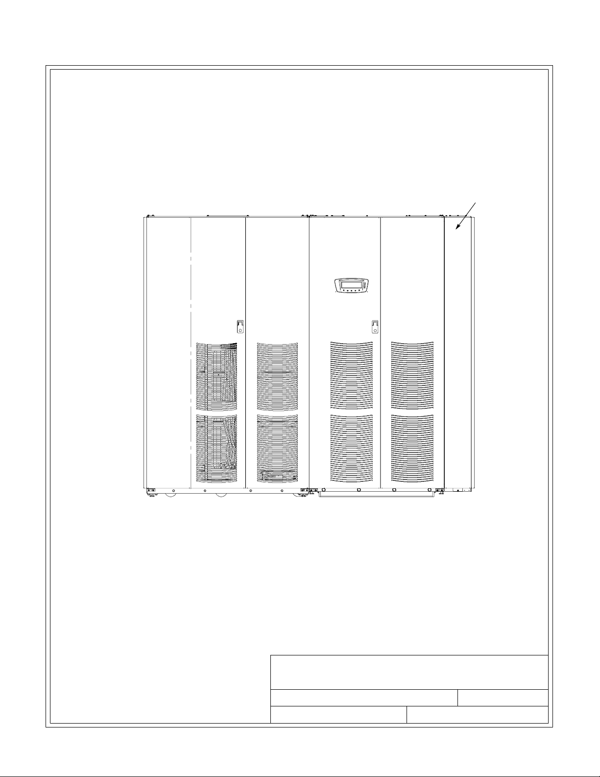
SIDECAR
A-2
BATTERY CABINET
80 kVA UPS
CABINET
TYPICAL MAINTENANCE BYPASS OR
STANDALO NE PARALLEL REDUNDANT CONFIGURATION
DESCRIPTION:
DRAWING NO: SHEET:
REVISION:
EATON Powerware®9390 UPS Sidecar Installation and Operation Manual S 164201586 Rev E www.powerware.com
TYPICAL POWERWARE 9390 UPS SYSTEM
WITH UPS SIDECAR
164201546---1
DATE:
1of3
031505A
Page 53
INSTALLATION INFORMATION
SIDECAR
BATTERY CABINET
160 kVA UPS
CABINET
TYPICAL MAINTENANCE BYPASS OR
STANDALO NE PARALLEL REDUNDANT CONFIGURATION
DESCRIPTION:
DRAWING NO: SHEET:
REVISION:
EATON Powerware®9390 UPS Sidecar Installation and Operation Manual S 164201586 Rev E www.powerware.com
TYPICAL POWERWARE 9390 UPS SYSTEM
WITH UPS SIDECAR
164201546---1
DATE:
031505A
2of3
A-3
Page 54

INSTALLATION INFORMATION
SIDECAR
A-4
BATTERY CABINET
80 kVA UPS
CABINET 1
80 kVA UPS
CABINET 2
BATTERY CABINET
TYPICAL LINE-UP-AND-MATCH PARALLEL REDUNDANT CONFIGURATION
DESCRIPTION:
DRAWING NO: SHEET:
REVISION:
EATON Powerware®9390 UPS Sidecar Installation and Operation Manual S 164201586 Rev E www.powerware.com
TYPICAL POWERWARE 9390 UPS SYSTEM
WITH UPS SIDECAR
164201546---1
DATE:
031505A
3of3
Page 55

INSTALLATION INFORMATION
1. The UPS Sidecar equipment operating environment must meet the weight requirements
shown in the applicable Powerware 9390 installation and operation manual, listed in
paragraph 1.5, plus 150 pounds for the UPS Sidecar. Size requirements are shown in
Drawing 164201546 ---8 starting on page A---68.
2. Donottiltcabinetsmorethan10˚ during handling.
3. Dimensions are in millimeters (inches).
4. The clearances required around the UPS Sidecar cabinet are shown in Table A.
Table A. UPS Sidecar Clearances
From T op of Cabinet Minimum clearance over the UPS Sidecar is
457.2 mm (18”) for ventilation
From Front of Cabinet 914.4 mm (36”)workingspace
From Back of Cabinet None Required
From Right Side of Cabinet None Required
5. The basic environmental requirements for operation of the UPS Sidecar are:
Ambient Temperature Range: 0 --- 4 0 ˚C (3 2 --- 1 0 4 ˚F)
Recommended Operating Range: 20---25˚C ( 68 --- 7 7˚F)
Maximum Relative Humidity: 95% noncondensing
DESCRIPTION:
DRAWING NO: SHEET:
REVISION:
EATON Powerware®9390 UPS Sidecar Installation and Operation Manual S 164201586 Rev E www.powerware.com
PHYSICAL FEATURES AND REQUIREMENTS
164201546---2 1 of 1
DATE:
031505A
A-5
Page 56

INSTALLATION INFORMATION
E1, E2, E3
K1
BATTERY
CONVERTER
SINGLE-FEED
JUMPER
(REMOVE FOR
DUAL-FEED)
RECTIFIER
AC INPUT
TO UPS
E6, E7,
E8, E12
K5
AC INPUT
TO BYPASS
A
E6, E7, E8
MAINTENANCE
BYPASS SWITCH
(MBP)
E4. E5
INVERTER
Powerware 9390 UPS CABINET
SERIAL NUMBER SEVENTH
DIGITAT“A”or“B”
NOTE 1. A minimum of two separate feeds with
upstream feeder breakers, or one feed
with two upstream feeder breakers, must
be provided: one for the UPS and one for
the UPS Sidecar bypass input. DO NOT
use one feed or a single feeder breaker to
supply both the UPS and the UPS
.
Sidecar
2. Remove jumper for dual -feed.
3. If the load requires a neutral, a bypass
neutral feeder must be supplied.
MAINTENANCE
ISOLATION SWITCH
(MIS)
C
E9, E10, E11
K3
UPS Sidecar
MAINTENANCE BYPASS CONFIGURATION
80/40, 80/50, 80/60 AND 80/80 kVA,
208/208V AND 480/480V
WITH UPS SERIAL NUMBER SEVENTH DIGIT AT
“A” O R “ B ”
DESCRIPTION:
DRAWING NO: SHEET:
REVISION:
UPS SIDECAR ONELINE DRAWINGS
164201546---3
DATE:
062806C
CRITICAL LOAD
AC OUTPUT
TO
1of11
A-6
EATON Powerware®9390 UPS Sidecar Installation and Operation Manual S 164201586 Rev E www.powerware.com
Page 57

INSTALLATION INFORMATION
E1, E2, E3
K1
BATTERY
CONVERTER
SINGLE-FEED
JUMPER
(REMOVE FOR
DUAL-FEED)
RECTIFIER
AC INPUT
TO UPS
E6, E7,
E8, E12
K5
AC INPUT
TO BYPASS
A
E6, E7, E8
MAINTENANCE
BYPASS SWITCH
(MBP)
E4. E5
INVERTER
Powerware 9390 UPS CABINET
SERIAL NUMBER SEVENTH
DIGITAT“A”
NOTE 1. A minimum of two separate feeds with
upstream feeder breakers, or one feed
with two upstream feeder breakers, must
be provided: one for the UPS and one for
the UPS Sidecar bypass input. DO NOT
use one feed or a single feeder breaker to
supply both the UPS and the UPS
.
Sidecar
2. Remove jumper for dual -feed.
3. If the load requires a neutral, a bypass
neutral feeder must be supplied.
MAINTENANCE
ISOLATION SWITCH
(MIS)
C
AC OUTPUT
E9, E10, E11
K3
TO
CRITICAL LOAD
UPS Sidecar
MAINTENANCE BYPASS CONFIGURATION
120/100 AND 120/120 kVA, 480/480V
160/100, 160/120, AND 160/160 kVA, 480/480V
WITH UPS SERIAL NUMBER SEVENTH DIGIT AT “A”
DESCRIPTION:
DRAWING NO: SHEET:
REVISION:
UPS SIDECAR ONELINE DRAWINGS
164201546---3
DATE:
062806B
2of11
EATON Powerware®9390 UPS Sidecar Installation and Operation Manual S 164201586 Rev E www.powerware.com
A-7
Page 58

INSTALLATION INFORMATION
AC INPUT
TO UPS
E1, E2, E3
K1
BATTERY
CONVERTER
SINGLE-FEED
JUMPER
(REMOVE FOR
DUAL-FEED)
RECTIFIER
E6, E7,
E8, E12
K5
AC INPUT
TO BYPASS
A
E6, E7, E8
MAINTENANCE
BYPASS SWITCH
(MBP)
E4. E5
INVERTER
Powerware 9390 UPS CABINET
SERIAL NUMBER SEVENTH
DIGITAT“B”ORHIGHER
NOTE 1. A minimum of two separate feeds with
upstream feeder breakers, or one feed
with two upstream feeder breakers, must
be provided: one for the UPS and one for
the UPS Sidecar bypass input. DO NOT
use one feed or a single feeder breaker to
supply both the UPS and the UPS
.
Sidecar
2. Remove jumper for dual -feed.
3. If the load requires a neutral, a bypass
neutral feeder must be supplied.
MAINTENANCE
ISOLATION SWITCH
(MIS)
E9, E10, E11
K3
UPS Sidecar
MAINTENANCE BYPASS CONFIGURATION
120/100 AND 120/120 kVA, 480/480V
WITH UPS SERIAL NUMBER SEVENTH DIGIT
AT “B” OR HIGHER
DESCRIPTION:
DRAWING NO: SHEET:
REVISION:
UPS SIDECAR ONELINE DRAWINGS
164201546---3
DATE:
C
AC OUTPUT
TO
CRITICAL LOAD
3of11
062806B
A-8
EATON Powerware®9390 UPS Sidecar Installation and Operation Manual S 164201586 Rev E www.powerware.com
Page 59

INSTALLATION INFORMATION
AC INPUT
TO UPS
E1, E2, E3
K1
BATTERY
CONVERTER
(SEE NOTE 2
DUAL-FEED)
RECTIFIER
E6, E7,
E8, E12
K5
AC INPUT
TO BYPASS
A
E6, E7, E8
MAINTENANCE
BYPASS SWITCH
(MBP)
E4. E5
INVERTER
Powerware 9390 UPS CABINET
SERIAL NUMBER SEVENTH
DIGITAT“B”ORHIGHER
NOTE 1. A minimum of two separate feeds with
upstream feeder breakers, or one feed
with two upstream feeder breakers, must
be provided: one for the UPS and one for
the UPS Sidecar bypass input. DO NOT
use one feed or a single feeder breaker to
supply both the UPS and the UPS
.
Sidecar
2. Move bypass contactor wires to
bypass terminals for dual-feed.
3. If the load requires a neutral, a bypass
neutral feeder must be supplied.
MAINTENANCE
ISOLATION SWITCH
(MIS)
E9, E10, E11
K3
UPS Sidecar
MAINTENANCE BYPASS CONFIGURATION
160/100, 160/120, AND 160/160 kVA, 480/480V
WITH UPS SERIAL NUMBER SEVENTH DIGIT
AT “B” OR HIGHER
DESCRIPTION:
DRAWING NO: SHEET:
REVISION:
UPS SIDECAR ONELINE DRAWINGS
164201546---3
DATE:
062806B
C
AC OUTPUT
TO
CRITICAL LOAD
4of11
EATON Powerware®9390 UPS Sidecar Installation and Operation Manual S 164201586 Rev E www.powerware.com
A-9
Page 60

INSTALLATION INFORMATION
AC INPUT
TO BYPASS
A
E6, E7, E8
E4. E5
K1
BATTERY
CONVERTER
SINGLE-FEED
JUMPER
(REMOVE FOR
DUAL-FEED)
RECTIFIER
INVERTER
BYPASS INPUT
BREAKER (BIB)
K5
MAINTENANCE
BYPASS SWITCH
(MBP)
MAINTENANCE
ISOLATION SWITCH
(MIS)
C
AC OUTPUT
E9, E10, E11
K3
TO
CRITICAL LOAD
A-10
Powerware 9390 UPS CABINET
SERIAL NUMBER SEVENTH
DIGITAT“A”or“B”
UPS Sidecar
MAINTENANCE BYP ASS WITH BIB CONFIGURATION
40/20, 40/30, 40/40, 80/40, 80/50, 80/60, AND 80/80 kVA,
208/208V AND 480/480V
WITH UPS SERIAL NUMBER SEVENTH DIGIT AT “A” OR “B”
NOTE 1. Remove jumper for dual -feed.
2. If the load requires a neutral, a bypass
neutral feeder must be supplied.
EATON Powerware®9390 UPS Sidecar Installation and Operation Manual S 164201586 Rev E www.powerware.com
DESCRIPTION:
DRAWING NO: SHEET:
UPS SIDECAR ONELINE DRAWINGS
164201546---3 5 of 11
REVISION:
DATE:
062806B
Page 61

AC INPUT
TO BYPASS
A
E6, E7, E8
INSTALLATION INFORMATION
E4. E5
K1
BATTERY
CONVERTER
SINGLE-FEED
JUMPER
(REMOVE FOR
DUAL-FEED)
RECTIFIER
INVERTER
BYPASS INPUT
BREAKER (BIB)
K5
MAINTENANCE
BYPASS SWITCH
(MBP)
MAINTENANCE
ISOLATION SWITCH
(MIS)
C
AC OUTPUT
E9, E10, E11
K3
TO
CRITICAL LOAD
Powerware 9390 UPS CABINET
SERIAL NUMBER SEVENTH
DIGITAT“A”
MAINTENANCE BYP ASS WITH BIB CONFIGURATION
120/100 AND 120/120 kVA, 480/480V
160/100, 160/120, AND 160/160 kVA, 480/480V
WITH UPS SERIAL NUMBER SEVENTH DIGIT AT “A”
NOTE 1. Remove jumper for dual -feed.
2. If the load requires a neutral, a bypass
neutral feeder must be supplied.
EATON Powerware®9390 UPS Sidecar Installation and Operation Manual S 164201586 Rev E www.powerware.com
UPS Sidecar
DESCRIPTION:
DRAWING NO: SHEET:
REVISION:
UPS SIDECAR ONELINE DRAWINGS
164201546---3 6 of 11
DATE:
062806B
A-11
Page 62

INSTALLATION INFORMATION
AC INPUT
TO BYPASS
A
E6, E7, E8
BYPASS INPUT
BREAKER (BIB)
SINGLE-FEED
JUMPER
(REMOVE FOR
K1
DUAL-FEED)
RECTIFIER
K5
MAINTENANCE
BYPASS SWITCH
(MBP)
BATTERY
CONVERTER
E4. E5
MAINTENANCE
ISOLATION SWITCH
(MIS)
INVERTER
K3
E9, E10, E11
Powerware 9390 UPS CABINET
SERIAL NUMBER SEVENTH
DIGITAT“B”ORHIGHER
UPS Sidecar
MAINTENANCE BYP ASS WITH BIB CONFIGURATION
120/100 AND 120/120 kVA, 480/480V
WITH UPS SERIAL NUMBER SEVENTH DIGIT AT “B” OR HIGHER
C
AC OUTPUT
TO
CRITICAL LOAD
A-12
NOTE 1. Remove jumper for dual -feed.
2. If the load requires a neutral, a bypass
neutral feeder must be supplied.
DESCRIPTION:
DRAWING NO: SHEET:
UPS ONLINE ONELINE DRAWINGS
164201546---3 7 of 11
REVISION:
EATON Powerware®9390 UPS Sidecar Installation and Operation Manual S 164201586 Rev E www.powerware.com
DATE:
062806B
Page 63

INSTALLATION INFORMATION
AC INPUT
TO BYPASS
A
E6, E7, E8
BYPASS INPUT
BREAKER (BIB)
(SEE NOTE 1
DUAL-FEED)
K1
K5
MAINTENANCE
BYPASS SWITCH
RECTIFIER
(MBP)
BATTERY
CONVERTER
E4. E5
MAINTENANCE
ISOLATION SWITCH
(MIS)
INVERTER
K3
E9, E10, E11
Powerware 9390 UPS CABINET
SERIAL NUMBER SEVENTH
DIGITAT“B”ORHIGHER
UPS Sidecar
MAINTENANCE BYP ASS WITH BIB CONFIGURATION
160/100, 160/120, and 160/160 kVA, 480/480V
WITH UPS SERIAL NUMBER SEVENTH DIGIT AT “B” OR HIGHER
C
AC OUTPUT
TO
CRITICAL LOAD
NOTE 1. Move bypass contactor wires to
bypass terminals for dual-feed.
2. If the load requires a neutral, a bypass
neutral feeder must be supplied.
EATON Powerware®9390 UPS Sidecar Installation and Operation Manual S 164201586 Rev E www.powerware.com
DESCRIPTION:
DRAWING NO: SHEET:
REVISION:
UPS SIDECAR ONELINE DRAWINGS
164201546---3 8 of 11
DATE:
062806B
A-13
Page 64
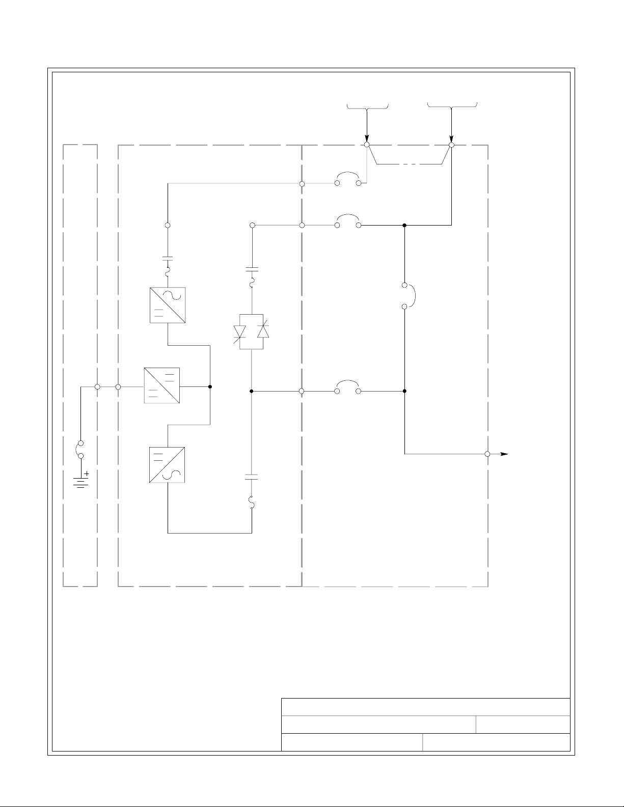
INSTALLATION INFORMATION
K1
BATTERY
CONVERTER
RECTIFIER
AC INPUT
TO UPS
B
E1, E2, E3
RECTIFIER INPUT
BREAKER (RIB)
BYPASS INPUT
BREAKER (BIB)
K5
SINGLE-FEED
JUMPER
(REMOVE FOR
DUAL-FEED)
AC INPUT
TO BYPASS
A
E6, E7, E8
MAINTENANCE
BYPASS SWITCH
(MBP)
E4. E5
INVERTER
Powerware 9390 UPS CABINET
MAINTENANCE BYPASS WITH BIB AND RIB
40/20, 40/30, 40/40, 208/208V,
120/100, 120/120 kVA, 480/480V and
160/100, 160/120, 160/160 kVA, 480/480V
MAINTENANCE
ISOLATION SWITCH
(MIS)
C
AC OUTPUT
E9, E10, E11
K3
TO
CRITICAL LOAD
UPS Sidecar
A-14
NOTE 1. Remove jumper for dual -feed.
2. If the load requires a neutral, a bypass
neutral feeder must be supplied.
DESCRIPTION:
DRAWING NO: SHEET:
UPS SIDECAR ONELINE DRAWINGS
164201546---3
REVISION:
EATON Powerware®9390 UPS Sidecar Installation and Operation Manual S 164201586 Rev E www.powerware.com
DATE:
9of11
092107C
Page 65

INSTALLATION INFORMATION
K1
BATTERY
CONVERTER
RECTIFIER
(RELOCATE F
TO HERE OR
DUAL-FEED)
MAINTENANCE
BYPASS SWITCH
(MBP)
AC INPUT
TO BYPASS
A
E6, E7, E8
AC INPUT
TO UPS
B
E1, E2, E3
RECTIFIER INPUT
BREAKER (RIB)
BYPASS INPUT
BREAKER (BIB)
K5
SINGLE-FEED
JUMPER
(REMOVE FOR
DUAL-FEED)
E4. E5
INVERTER
Powerware 9390 UPS CABINET
MAINTENANCE BYPASS WITH BIB AND RIB
80/40, 80/50, 80/60, 80/80 kVA, 480/480V,
NOTE 1. Remove jumper for dual -feed.
2. For 80kVA 480/480V dual-feed, move
BIB wires from E1, E2, E3 to E6, E7, E8.
3. If the load requires a neutral, a bypass
neutral feeder must be supplied.
MAINTENANCE
ISOLATION SWITCH
(MIS)
E9, E10, E11
K3
UPS Sidecar
DESCRIPTION:
DRAWING NO: SHEET:
REVISION:
UPS SIDECAR ONELINE DRAWINGS
164201546---3
DATE:
C
AC OUTPUT
TO
CRITICAL LOAD
10 of 11
092107C
EATON Powerware®9390 UPS Sidecar Installation and Operation Manual S 164201586 Rev E www.powerware.com
A-15
Page 66

INSTALLATION INFORMATION
BATTERY
CABINET
BATTERY
BREAKER
AB
AB
** **
UPM 1
E1
E2
E3
SEENOTE2
K1
FUSE
RECTIFIER
CONVERTER
INVERTER
FUSE
K3
E4. E5
C
K5
FUSE
BATTERY
STATIC
SWITCH
E6
E7
E8
E12
UPS Sidecar
MOB 1
SLB
(OPTIONAL)
MOB 2
UPM 2
E1
E2
E3
SEENOTE2
FUSE
RECTIFIER
BATTERY
CONVERTER
K5
K1
FUSE
INVERTER
FUSE
K3
STATIC
SWITCH
E4. E5
E6
E7
E8
E12
C
BATTERY
CABINET
BATTERY
BREAKER
E9, E10, E11
D
OUTPUT TO
CRITICAL LOAD
A --- AC Input to UPS Rectifier (dual-feed)
B --- AC Input to UPS Rectifier (single-feed) and Bypass (single- and dual-feed)
C --- DC Input from Battery
D --- Output to Critical Load
* --- Overcurrent Protection Provided by Others
TYPICAL PARALLEL REDUNDANT SYSTEM
(1+1 CONFIGURATION)
NOTE 1. UPM and system bypass input feeds
must come from the same source.
2. Remove jumper for dual -feed.
3. If the load requires a neutral, a bypass
neutral feeder must be supplied.
DESCRIPTION:
DRAWING NO: SHEET:
REVISION:
UPS SIDECAR ONELINE DRAWINGS
164201546---3
DATE:
031505A
11 of 11
A-16
EATON Powerware®9390 UPS Sidecar Installation and Operation Manual S 164201586 Rev E www.powerware.com
Page 67

Ta b le B . INPUT/OUTPUT Ratings & External Wiring Requirements for
A
A
Powerware 9390 UPS Sidecar (Maintenance Bypass) 208/208V
Basic Unit Rating
Input and Bypass Input
Output
AC Input to Maintenance Bypass (without
BIB or RIB, or dual feed with BIB and RIB)
(3) Phases, (1) Neutral---if required,
(1) Ground
Minimum Conductor Size
Number per Phase
AC Input to Maintenance Bypass (single
feed with BIB, or single feed with BIB and RIB)
(3) Phases, (1) Neutral---if required,
(1) Ground
Minimum Conductor Size
Number per Phase
AC Input to Optional RIB
(3) Phases, (1) Ground
Minimum Conductor Size
Number per Phase
AC Output to Critical Load
Full Load Current
(3) Phases, (1) Neutral---if required,
(1) Ground
Minimum Conductor Size
Number per Phase
INSTALLATION INFORMATION
Units Rating 50/60 Hz
UPS kVA 20 30 40 50 60 80
AWG or kcmil
AWG or kcmil
B
AWG or kcmil
VOLTS
VOLTS
AMPS 56 83 111 139 167 222
(each)
AMPS 60 90 125 155 185 240
(each)
AMPS 60 90 125 155 185 240
(each)
AMPS 56 83 111 139 167 222
208
208
2
(1)
2
(1)
2
(1)
208
208
2/0
(1)
2/0
(1)
2/0
(1)
208
208
2/0
(1)
2/0
(1)
2/0
(1)
208
208
4/0
(1)
4/0
(1)
4/0
(1)
C
AWG or kcmil
(each)
(1)
2
2/0
(1)
2/0
(1)
4/0
(1)
208
208
250
(1)
250
(1)
250
(1)
250
(1)
208
208
2/0
(2)
2/0
(2)
2/0
(2)
2/0
(2)
NOTE Callout letters A, B, and C map to drawing 164201546---3, sheets 1 of 11,
5 of 11, and 9 of 11.
DESCRIPTION:
DRAWING NO: SHEET:
REVISION:
POWER WIRING INSTALLATION NOTES
164201546---4
D
DATE:
092107
1of10
EATON Powerware®9390 UPS Sidecar Installation and Operation Manual S 164201586 Rev E www.powerware.com
A-17
Page 68

INSTALLATION INFORMATION
Basic Unit Rating
Input and Bypass Input
Output
AC Input to Maintenance
Bypass (without BIB or RIB, or
dual feed with BIB and RIB)
(3) Phases, (1) Neutral---if required,
(1) Ground
Minimum Conductor Size
Number per Phase
AC Input to Maintenance
Bypass (single feed with BIB, or
single feed with BIB and RIB)
(3) Phases, (1) Neutral---if required,
(1) Ground
Minimum Conductor Size
Number per Phase
AC Input to Optional RIB
(3) Phases, (1) Ground
Minimum Conductor Size
Number per Phase
AC Output to Critical Load
Full Load Current
(3) Phases, (1) Neutral---if required,
(1) Ground
Minimum Conductor Size
Number per Phase
Ta b le C . INPUT/OUTPUT Ratings & External Wiring Requirements for
Powerware 9390 UPS Sidecar (Maintenance Bypass) 480/480V
Units Rating 50/60 Hz
UPS kVA 20 30 40 50 60 80 100 120 160
VOLTS
VOLTS
AMPS 24 36 48 60 72 96 120 144 193
480
480
480
480
480
480
480
480
480
480
480
480
A
AWG or kcmil
(each)
AMPS 30 40 55 67 80 105 130 160 210
(1)
6
(1)
4
(1)
4
(1)
2
(1)
1
1/0
(1)
A
AWG or kcmil
B
AWG or kcmil
(each)
AMPS 30 40 55 67 80 105 130 160 210
(each)
AMPS 24 36 48 60 72 96 120 144 193
(1)
(1)
6
6
(1)
(1)
4
4
(1)
(1)
4
4
(1)
(1)
2
2
(1)
(1)
1
1/0
(1)
1
1/0
(1)
C
AWG or kcmil
(each)
(1)
6
(1)
4
(1)
4
(1)
2
(1)
1
1/0
(1)
480
480
4/0
(1)
4/0
(1)
4/0
(1)
4/0
(1)
480
480
4/0
(1)
4/0
(1)
4/0
(1)
4/0
(1)
480
480
1/0
(2)
1/0
(2)
1/0
(2)
1/0
(2)
NOTE Callout letters A, B, and C map to drawing 164201546---3, sheets 1 of 11,
2of11,3of11,4of11,5of11,6of11,7of11,8of11,and9of11.
DESCRIPTION:
DRAWING NO: SHEET:
REVISION:
POWER WIRING INSTALLATION NOTES
164201546---4 2 of 10
D
DATE:
061507
A-18
EATON Powerware®9390 UPS Sidecar Installation and Operation Manual S 164201586 Rev E www.powerware.com
Page 69

Table D. INPUT/OUTPUT Ratings & External Wiring Requirements for
Powerware 9390 UPS Sidecar (1+1 Parallel Redundant) 208V
Basic Unit Rating
Input and Bypass Input
Output
AC Input from UPM
Full Load Current for each Module
(3) Phases, (1) Neutral ---if required, (1) Ground
Minimum Conductor Size for each Module
NumberperPhaseforeachModule
AC Output to Critical Load
Full Load Current
(3) Phases, (1) Neutral --- if required, (1) Ground
Minimum Conductor Size
Number per Phase
INSTALLATION INFORMATION
Units Rating 50/60 Hz
UPS kVA
VOLTS
VOLTS
AMPS
For customer-supplied wiring in a standalone
—
installation, refer to the applicable Powerware 9390
installation and operation manual, listed in paragraph
1.5, for wire size. Wiring for line-up-and-match
installation is factory-supplied.
AMPS
40 50 60 80
208
208
208
208
111 139 167 222
111 139 167 222
D
AWG or kcmil
(each)
2/0
(1)
4/0
(1)
208
208
250
(1)
208
208
2/0
(2)
NOTE Callout letter D maps to drawing 164201546 ---3, sheet 11 of 11.
Table E. INPUT/OUTPUT Ratings & External Wiring Requirements for
Powerware 9390 UPS Sidecar (1+1 Parallel Redundant) 480V
Units Rating 50/60 Hz
Basic Unit Rating
Input and Bypass Input
Output
AC Input from UPM
Full Load Current for each Module
(3) Phases, (1) Neu tral - --if required,
(1) Ground
Minimum Conductor Size for each
Module
NumberperPhaseforeachModule
AC Output to Critical Load
Full Load Current
(3) Phases, (1) Neutral ---if required,
(1) Ground
Minimum Conductor Size
Number per Phase
UPS
kVA
VOLTS
VOLTS
AMPS
20
(See
Note 2)
480
480
48 48 48 60 72 96 120 144 192
—
For customer-supplied wiring in a standalone installation, refer to the applicable
Powerware 9390 installation and operation manual, listed in paragraph 1.5, for wire
size. Wiring for line-u p -and- matc h installation is factory-supplied.
AMPS
48 48 48 60 72 96 120 144 192
D
AWG or
kcmil
(each)
4
(1)
30
(See
Note 2)
480
480
4
(1)
40 50 60 80 100 120 160
480
480
480
480
4
(1)2(1)1(1)
480
480
480
480
1/0
(1)
480
480
4/0
(1)
480
480
4/0
(1)
480
480
1/0
(2)
NOTE 1. Callout letter D maps to drawing 164201546 --- 3, sheet 11 of 11.
NOTE 2. 40/20 kVA and 40/30 kVA parallel systems must be wired same as a 40/40 kVA.
DESCRIPTION:
DRAWING NO: SHEET:
REVISION:
EATON Powerware®9390 UPS Sidecar Installation and Operation Manual S 164201586 Rev E www.powerware.com
POWER WIRING INSTALLATION NOTES
164201546---4 3 of 10
D
DATE:
092107
A-19
Page 70

INSTALLATION INFORMATION
Read and understand the following notes while planning and performing the installation:
1. Refer to national and local electrical codes for acceptable external wiring practices.
2. Material and labor for external wiring requirements are to be provided by designated
personnel.
CAUTION
Specified wiring and the MOB and SLB breakers for the UPS Sidecar are
rated for parallel redundant service only. DO NOT use as a parallel
capacity system.
CAUTION
Parallel system wiring length should be in accordance with the parallel
drawings
installation and operation manual, listed in paragraph 1.5. Correct wire
length
mode.
found in the appendix of the applicable Powerware 9390
ensures approximate equal current sharing when in Static bypass
3. For external input wiring, use 90°C copper wire. See the appropriate column in Table B
through T able E. Wire sizes are based on using the specified breakers.
4. Wire ampacities are chosen from Table 310 ---16 of the NEC. Input wire is 90°C
specification.
5. If a Bypass Input Breaker is not installed, a minimum of two separate feeds with upstream
feeder breakers, or one feed with two upstream feeder breakers, must be provided: one
for the UPS and one for the UPS Sidecar bypass input. DO NOT use one feed or a
single-feeder breaker to supply both the UPS and Sidecar.
6. Refer to Section I of this manual for installation instructions.
7. Refer to the applicable Powerware 9390 installation and operation manual, listed in
paragraph 1.5, for UPS cabinet wiring requirements, and conduit and terminal locations.
8. Refer to the applicable Powerware 9390 installation and operation manual, listed in
paragraph 1.5, for parallel system power and control wiring requirements.
9. Terminals are UL and CSA rated at 90˚C. Refer to Table F through Table K for power cable
terminations. Drawing 164201546---6, starting on page A---30, shows the location of the
power cable terminals inside the UPS Sidecar cabinet.
10. Per NEC article 300-20(a), all three-phaseconductorsmustberuninthesameconduit.
Neutral and ground must be run in the same conduit as the phase conductors.
11. If input or output neutrals are required for Maintenance Bypass configurations, wire the
neutrals to the neutral terminals located inside the UPS cabinet. For Maintenance Bypass
configurations, wire grounds to the ground terminals located inside the UPS cabinet.
A-20
12. 40/20 kVA and 40/30 kVA parallel systems must be wired for 40/40 kVA.
DESCRIPTION:
DRAWING NO: SHEET:
REVISION:
EATON Powerware®9390 UPS Sidecar Installation and Operation Manual S 164201586 Rev E www.powerware.com
POWER WIRING INSTALLATION NOTES
164201546---4 4 of 10
C
DATE:
061507
Page 71

Table F. UPS Sidecar Maintenance Bypass Power Cable Terminations
Terminal Function Function
AC Input to Maintenance
Bypass or Optional BIB
AC Input to Optional RIB
AC Output to Critical Load
Table G. UPS Sidecar Maintenance Bypass Power Cable Terminations
40/20, 40/30, 40/40, 208/208V and 80/40, 80/50, 80/60, 80/80, 480/480V
Terminal Function Function
AC Input to Maintenance
Bypass
Bypass Input with Optional
BIB (Terminal Block)
Rectifier Input with Optional
RIB (Terminal Block)
AC Output to Critical Load
Table H. UPS Sidecar Maintenance Bypass Power Cable Terminations
Terminal Function Function
Bypass Input with Optional
BIB (Terminal Block)
Rectifier Input with Optional
RIB (Terminal Block)
AC Input to Maintenance
Bypass
AC Output to Critical Load
(Terminal Block)
INSTALLATION INFORMATION
40/20, 40/30, 40/40, 480/480V
Size of Pressure
Termination
Phase A 1 --- # 14 --- 2 /0
Phase B 1 --- # 14 --- 2 / 0
Phase C 1 --- # 1 4 --- 2 / 0
Phase A 1 --- # 14 --- 3 /0 5.6 (50) Slot
Phase B 1 --- # 14 --- 3 / 0 5.6 (50) Slot
Phase C 1 --- # 1 4 --- 3 / 0 5.6 (50) Slot
Phase A 1 --- # 14 --- 2 /0
Phase B 1 --- # 14 --- 2 / 0
Phase C 1 --- # 1 4 --- 2 / 0 13.5 (120) 3/16” Hex
Size of Pressure
Termination
Phase A 1 --- # 4 --- 3 5 0 k cm i l
Phase B 1 --- # 4 --- 3 5 0 k cm i l
Phase C 1 --- # 4 --- 3 5 0 k cm i l
Phase A 1 --- # 14 --- 2 /0
Phase B 1 --- # 14 --- 2 / 0
Phase C 1 --- # 1 4 --- 2 / 0
Phase A 1 --- # 14 --- 2 /0
Phase B 1 --- # 14 --- 2 / 0
Phase C 1 --- # 1 4 --- 2 / 0
Phase A 1 --- # 14 --- 2 /0
Phase B 1 --- # 14 --- 2 / 0
Phase C 1 --- # 1 4 --- 2 / 0 13.5 (120) 3/16” Hex
Tightening Torque
Nm (lb in)
13.5 (120)
13.5 (120)
13.5 (120)
13.5 (120)
13.5 (120)
Tightening Torque
Nm (lb in)
20.0 (177)
20.0 (177)
20.0 (177)
13.5 (120)
13.5 (120)
13.5 (120)
13.5 (120)
13.5 (120)
13.5 (120)
13.5 (120)
13.5 (120)
Type
Screw
3/16” Hex
3/16” Hex
3/16” Hex
3/16” Hex
3/16” Hex
Type
Screw
M4 Hex
M4 Hex
M4 Hex
3/16” Hex
3/16” Hex
3/16” Hex
3/16” Hex
3/16” Hex
3/16” Hex
3/16” Hex
3/16” Hex
120/100, 120/120, 480/480V
Size of Pressure
Termination
Phase A 1 --- # 6 --- 5 0 0 k cm i l
Phase B 1 --- # 6 --- 5 0 0 k cm i l
Phase C 1 --- # 6 --- 5 0 0 k cm i l
Phase A 1 --- # 6 --- 5 0 0 k cm i l
Phase B 1 --- # 6 --- 5 0 0 k cm i l
Phase C 1 --- # 6 --- 5 0 0 k cm i l
Phase A 1 --- # 4 --- 3 5 0 k cm i l
Phase B 1 --- # 4 --- 3 5 0 k cm i l
Phase C 1 --- # 4 --- 3 5 0 k cm i l
Phase A 1 --- # 6 --- 5 0 0 k cm i l
Phase B 1 --- # 6 --- 5 0 0 k cm i l
Phase C 1 --- # 6 --- 5 0 0 k cm i l
Tightening Torque
Nm (lb in)
56.5 (500)
56.5 (500)
56.5 (500)
56.5 (500)
56.5 (500)
56.5 (500)
20.0 (177)
20.0 (177)
20.0 (177)
56.5 (500)
56.5 (500)
56.5 (500)
Type
Screw
1/2” Hex
1/2” Hex
1/2” Hex
1/2” Hex
1/2” Hex
1/2” Hex
M4 Hex
M4 Hex
M4 Hex
1/2” Hex
1/2” Hex
1/2” Hex
DESCRIPTION:
DRAWING NO: SHEET:
REVISION:
EATON Powerware®9390 UPS Sidecar Installation and Operation Manual S 164201586 Rev E www.powerware.com
POWER WIRING INSTALLATION NOTES
164201546---4 5 of 10
D
DATE:
092107
A-21
Page 72

INSTALLATION INFORMATION
Table I. UPS Sidecar Maintenance Bypass Power Cable Terminations
80/40, 80/50, 80/60, 80/80, 208/208V and 160/100, 160/120, 160/160, 480/480V
Terminal Function Function
AC Input to Maintenance
Bypass or Optional BIB
AC Input to Optional RIB
AC Output to Critical Load
Phase A
Phase B
Phase C
Phase A
Phase B
Phase C
Phase A
Phase B
Phase C
Size of Pressure
Termination
1 --- 2/0--- 250 kcmil
1 --- 2/0--- 500 kcmil
1 --- 2/0--- 250 kcmil
1 --- 2/0--- 500 kcmil
1 --- 2/0--- 250 kcmil
1 --- 2/0--- 500 kcmil
1 --- 2/0--- 250 kcmil
1 --- 2/0--- 500 kcmil
1 --- 2/0--- 250 kcmil
1 --- 2/0--- 500 kcmil
1 --- 2/0--- 250 kcmil
1 --- 2/0--- 500 kcmil
1 --- 2/0--- 250 kcmil
1 --- 2/0--- 500 kcmil
1 --- 2/0--- 250 kcmil
1 --- 2/0--- 500 kcmil
1 --- 2/0--- 250 kcmil
1 --- 2/0--- 500 kcmil
Tightening Torque
Nm (lb in)
31.1 (275)
31.1 (275)
31.1 (275)
31.1 (275)
31.1 (275)
31.1 (275)
31.1 (275)
31.1 (275)
31.1 (275)
31.1 (275)
31.1 (275)
31.1 (275)
31.1 (275)
31.1 (275)
31.1 (275)
31.1 (275)
31.1 (275)
31.1 (275)
Type
Screw
5/16” Hex
3/8” Hex
5/16” Hex
3/8” Hex
5/16” Hex
3/8” Hex
5/16” Hex
3/8” Hex
5/16” Hex
3/8” Hex
5/16” Hex
3/8” Hex
5/16” Hex
3/8” Hex
5/16” Hex
3/8” Hex
5/16” Hex
3/8” Hex
Table J. UPS Sidecar 1+1 Parall e l Redundant Power Cable Terminations
40/20, 40/30, 40/40, 208/208V and 80/40, 80/50, 80/60, 80/80, 480/480V
Size of Pressure
Terminal Function Function
AC Input from UPM2 to
MOB 2 (standalone
installation)
AC Output to Critical Load
(without SLB) Terminal
Block
AC Output to Critical Load
(with SLB)
Phase A 1 --- # 4 --- 3 5 0 k c mi l
Phase B 1 --- # 4 --- 3 5 0 k cm i l
Phase C 1 --- # 4 --- 3 5 0 k cm i l
Phase A 1 --- # 1 4 --- 2 / 0
Phase B 1 --- # 14 --- 2 /0
Phase C 1 --- # 14 --- 2 / 0
Phase A 1 --- # 4 --- 3 5 0 k c mi l
Phase B 1 --- # 4 --- 3 5 0 k cm i l
Termination
Phase C 1 --- # 4 --- 3 5 0 k cm i l
Neutral (80/480) Neutral 4 --- # 14 --- 1 / 0 5.6 (50) Slotted
Neutral (40/208) Neutral 8 --- # 6 --- 2 5 0 k cm i l 42.4 (375) 5/16” Hex
Ground Ground 2 --- # 14 --- 1 / 0 5.6 (50) Slotted
Tightening Torque
Nm (lb in)
20.3 (180)
20.3 (180)
20.3 (180)
13.5 (120)
13.5 (120)
13.5 (120)
20.3 (180)
20.3 (180)
20.3 (180)
Type
Screw
3/16” Hex
3/16” Hex
3/16” Hex
3/16” Hex
3/16” Hex
3/16” Hex
3/16” Hex
3/16” Hex
3/16” Hex
A-22
DESCRIPTION:
DRAWING NO: SHEET:
REVISION:
EATON Powerware®9390 UPS Sidecar Installation and Operation Manual S 164201586 Rev E www.powerware.com
POWER WIRING INSTALLATION NOTES
164201546---4 6 of 10
D
DATE:
092107
Page 73

INSTALLATION INFORMATION
Table K. UPS Sidecar 1+1 Paral lel Redundant Power Cabl e Terminations
120/100, 120/120 kVA 480/480V
Size of Pressure
Terminal Function Function
AC Input from UPM2 to
MOB 2 (standalone
installation)
AC Output to Critical Load
(without SLB)
AC Output to Critical Load
(with SLB)
Neutral Neutral 8 --- # 6 --- 2 5 0 k cm i l 42.4 (375) 5/16” Hex
Ground Ground 4 --- # 14 --- 1 / 0 5.6 (50) Slotted
Phase A 1 --- # 4 --- 3 5 0 k c mi l
Phase B 1 --- # 4 --- 3 5 0 k cm i l
Phase C 1 --- # 4 --- 3 5 0 k cm i l
Phase A 1 --- # 6 --- 5 0 0 k c mi l 56.5 (500) 1/2 Hex
Phase B 1 --- # 6 --- 5 0 0 k cm i l 56.5 (500) 1/2 Hex
Phase C 1 --- # 6 --- 5 0 0 k cm i l 56.5 (500) 1/2 Hex
Phase A 1 --- # 4 --- 3 5 0 k c mi l 20.3 (180) 3/16” Hex
Phase B 1 --- # 4 --- 3 5 0 k cm i l 20.3 (180) 3/16” Hex
Phase C 1 --- # 4 --- 3 5 0 k cm i l 20.3 (180) 3/16” Hex
Termination
Tightening Torque
Nm (lb in)
20.3 (180)
20.3 (180)
20.3 (180)
Type
Screw
3/16” Hex
3/16” Hex
3/16” Hex
Table L. UPS Sidecar 1+1 Parallel Redundant Power Cable Terminations
80/40, 80/50, 80/60, 80/80 kVA 208/208V
Size of Pressure
Terminal Function Function
AC Input from UPM2 to
MOB 2 (standalone
installation)
AC Output to Critical Load
(without SLB)
AC Output to Critical Load
(with SLB)
Neutral Neutral 8 --- # 6 --- 2 5 0 k cm i l 42.4 (375) 5/16” Hex
Ground Ground 4 --- # 14 --- 1 / 0 5.6 (50) Slotted
Phase A
Phase B
Phase C
Phase A
Phase B
Phase C
Phase A
Phase B
Phase C
Termination
1 --- 2/0--- 250 kcmil
1 --- 2/0--- 500 kcmil
1 --- 2/0--- 250 kcmil
1 --- 2/0--- 500 kcmil
1 --- 2/0--- 250 kcmil
1 --- 2/0--- 500 kcmil
1 --- 2/0--- 250 kcmil
1 --- 2/0--- 500 kcmil
1 --- 2/0--- 250 kcmil
1 --- 2/0--- 500 kcmil
1 --- 2/0--- 250 kcmil
1 --- 2/0--- 500 kcmil
1 --- 2/0--- 250 kcmil
1 --- 2/0--- 500 kcmil
1 --- 2/0--- 250 kcmil
1 --- 2/0--- 500 kcmil
1 --- 2/0--- 250 kcmil
1 --- 2/0--- 500 kcmil
Tightening Torque
Nm (lb in)
31.1 (275)
31.1 (275)
31.1 (275)
31.1 (275)
31.1 (275)
31.1 (275)
31.1 (275)
31.1 (275)
31.1 (275)
31.1 (275)
31.1 (275)
31.1 (275)
31.1 (275)
31.1 (275)
31.1 (275)
31.1 (275)
31.1 (275)
31.1 (275)
Type
Screw
5/16” Hex
3/8” Hex
5/16” Hex
3/8” Hex
5/16” Hex
3/8” Hex
5/16” Hex
3/8” Hex
5/16” Hex
3/8” Hex
5/16” Hex
3/8” Hex
5/16” Hex
3/8” Hex
5/16” Hex
3/8” Hex
5/16” Hex
3/8” Hex
13. Conduit is to be sized to accommodate one neutral conductor the same size as the phase
conductor and one #8 AWG ground conductor. If two neutral conductors or an oversized
neutral conductor are to be installed, size the conduit to accommodate the extra wire or
size. All Powerware 9390 products can accommodate a double-sized neutral.
14. External UPS Sidecar rectifier and bypass input overcurrent protection is not provided by
this product, but is required by codes. Refer to Table B through Table E for wiring
requirements.
DESCRIPTION:
DRAWING NO: SHEET:
REVISION:
EATON Powerware®9390 UPS Sidecar Installation and Operation Manual S 164201586 Rev E www.powerware.com
POWER WIRING INSTALLATION NOTES
164201546---4 7 of 10
E
DATE:
092107
A-23
Page 74

INSTALLATION INFORMATION
Table M . UPS Sidecar 1+1 Parallel Redundant Power Cable Terminations
Terminal Function Function
AC Input from UPM2 to
MOB 2 (standalone
installation)
AC Output to Critical Load
(without SLB)
AC Output to Critical Load
(with SLB)
Neutral Neutral 8 --- # 6 --- 2 5 0 k cm i l 42.4 (375) 5/16” Hex
Ground Ground 4 --- # 14 --- 1 / 0 5.6 (50) Slotted
160/100, 160/120, 160/160 kVA 480/480V
Phase A
Phase B
Phase C
Phase A
Phase B
Phase C
Phase A
Phase B
Phase C
Size of Pressure
Termination
1 --- 2/0--- 250 kcmil
1 --- 2/0--- 500 kcmil
1 --- 2/0--- 250 kcmil
1 --- 2/0--- 500 kcmil
1 --- 2/0--- 250 kcmil
1 --- 2/0--- 500 kcmil
1 --- 2/0--- 250 kcmil
1 --- 2/0--- 500 kcmil
1 --- 2/0--- 250 kcmil
1 --- 2/0--- 500 kcmil
1 --- 2/0--- 250 kcmil
1 --- 2/0--- 500 kcmil
1 --- 2/0--- 250 kcmil
1 --- 2/0--- 500 kcmil
1 --- 2/0--- 250 kcmil
1 --- 2/0--- 500 kcmil
1 --- 2/0--- 250 kcmil
1 --- 2/0--- 500 kcmil
Tightening Torque
Nm (lb in)
31.1 (275)
31.1 (275)
31.1 (275)
31.1 (275)
31.1 (275)
31.1 (275)
31.1 (275)
31.1 (275)
31.1 (275)
31.1 (275)
31.1 (275)
31.1 (275)
31.1 (275)
31.1 (275)
31.1 (275)
31.1 (275)
31.1 (275)
31.1 (275)
Type
Screw
5/16” Hex
3/8” Hex
5/16” Hex
3/8” Hex
5/16” Hex
3/8” Hex
5/16” Hex
3/8” Hex
5/16” Hex
3/8” Hex
5/16” Hex
3/8” Hex
5/16” Hex
3/8” Hex
5/16” Hex
3/8” Hex
5/16” Hex
3/8” Hex
TableN.UPSSidecar1+1ParallelRedundantPowerCableTerminations
40/20, 40/30, 40/40 kVA 480/480V
Size of Pressure
Terminal Function Function
AC Input from UPM2 to
MOB 2 (standalone
installation)
AC Output to Critical Load
(without SLB) Terminal
Block
AC Output to Critical Load
(with SLB)
Phase A 1 --- # 1 4 --- 3 / 0
Phase B 1 --- # 14 --- 3 /0
Phase C 1 --- # 14 --- 3 / 0
Phase A 1 --- # 1 4 --- 2 / 0 13.5 (120) 3/16” Hex
Phase B 1 --- # 14 --- 2 /0 13.5 (120) 3/16” Hex
Phase C 1 --- # 14 --- 2 / 0 13.5 (120) 3/16” Hex
Phase A 1 --- # 1 4 --- 3 / 0 5.6 (50) Slotted
Phase B 1 --- # 14 --- 3 /0 5.6 (50) Slotted
Termination
Phase C 1 --- # 14 --- 3 / 0 5.6 (50) Slotted
Neutral Neutral 4 --- # 14 --- 1 / 0 5.6(50) Slotted
Ground Ground 2 --- # 14 --- 1 / 0 5.6 (50) Slotted
DESCRIPTION:
DRAWING NO: SHEET:
REVISION:
E
Tightening Torque
Nm (lb in)
5.6 (50)
5.6 (50)
5.6 (50)
Type
Screw
Slotted
Slotted
Slotted
POWER WIRING INSTALLATION NOTES
164201546---4 8 of 10
DATE:
092107
A-24
EATON Powerware®9390 UPS Sidecar Installation and Operation Manual S 164201586 Rev E www.powerware.com
Page 75

INSTALLATION INFORMATION
15. Table O lists the maximum rating for rectifier input circuit breakers and Table P lists the
maximum rating for bypass input circuit breakers.
Table O. Maximum UPS Sidecar Rectifier Input Circuit Breaker Ratings
UPS Sidecar Model
40 kVA
50 kVA
60 kVA
80 kVA
100 kVA
120 kVA
160 kVA
80% Rated 175A 70A
100% Rated 150A 60A
80% Rated 225A 100A
100% Rated 175A 80A
80% Rated 250A 125A
100% Rated 200A 90A
80% Rated 350A 150A
100% Rated 300A 125A
80% Rated N/A 200A
100% Rated N/A 150A
80% Rated N/A 225A
100% Rated N/A 175A
80% Rated N/A 300A
100% Rated N/A 250A
Input Voltage Rating
208V 480V
Table P. Maximum UPS Sidecar Bypass Input Circuit Breaker Ratings
UPS Sidecar Model
40 kVA
50 kVA
60 kVA
80 kVA
100 kVA
120 kVA
160 kVA
80% Rated 175A 70A
100% Rated 150A 60A
80% Rated 225A 100A
100% Rated 175A 80A
80% Rated 250A 125A
100% Rated 200A 90A
80% Rated 350A 150A
100% Rated 300A 125A
80% Rated N/A 200A
100% Rated N/A 150A
80% Rated N/A 225A
100% Rated N/A 175A
80% Rated N/A 300A
100% Rated N/A 250A
Input Voltage Rating
208V 480V
CAUTION
To reduce the risk of fire, connect only to a circuit provided with
maximum input circuit breaker current ratings from Table O in accordance
with the NEC, ANSI/NFPA 70.
DESCRIPTION:
DRAWING NO: SHEET:
REVISION:
EATON Powerware®9390 UPS Sidecar Installation and Operation Manual S 164201586 Rev E www.powerware.com
POWER WIRING INSTALLATION NOTES
164201546---4 9 of 10
C
DATE:
062206
A-25
Page 76

INSTALLATION INFORMATION
16. The MIS and SLB breakers on the 80 kVA, 120 kVA, and 160 kVA UPS Sidecars are
adjustable trip breakers and are set to maximum at the factory. During installation these
breakers must be adjusted for the site requirements using the dial on each breaker. The
MIS and SLB breakers on the 40 kVA UPS Sidecar are non-adjustable.
17. The continuous current (Ir) values for the corresponding lettered adjustment setting
marked on the MIS and SLB breakers are listed in Table Q.
Table Q. MIS and SLB Continuous Current (Ir) Settings
Breaker
Setting
A 250 100 N/A 100 N/A 250
B 300 125 N/A 125 N/A 300
C 350 150 N/A 150 N/A 350
D 400 160 N/A 160 N/A 400
E — 175 N/A 175 N/A —
F — 200 N/A 200 N/A —
G — 225 N/A 225 N/A —
H — 250 N/A 250 N/A —
80 kVA Continuous
Current (Ir)
120 kVA Continuous
Current (Ir)
160 kVA Continuous
Current (Ir)
208V 480V 208V 480V 208V 480V
A-26
DESCRIPTION:
DRAWING NO: SHEET:
REVISION:
EATON Powerware®9390 UPS Sidecar Installation and Operation Manual S 164201586 Rev E www.powerware.com
POWER WIRING INSTALLATION NOTES
164201546---4
DATE:
10 of 10
063006B
Page 77

INSTALLATION INFORMATION
UPS SIDECAR TOP ENTRY
CONDUIT LANDING FOR AC
INPUT AND OUTPUT.
(REMOVE PANEL TO DRILL OR
PUNCH CONDUIT HOLES.)
TOP VIEW
UPS SIDECAR BOTTOM ENTRY
CONDUIT LANDING FOR AC
INPUT AND OUTPUT.
(REMOVE PANEL TO DRILL OR
PUNCH CONDUIT HOLES.)
BOTTOM VIEW
80 KVA UPS
DESCRIPTION:
DRAWING NO: SHEET:
REVISION:
EATON Powerware®9390 UPS Sidecar Installation and Operation Manual S 164201586 Rev E www.powerware.com
CONDUIT AND WIRE ENTRY LOCATIONS
164201546---5
DATE:
031505A
1of3
A-27
Page 78

INSTALLATION INFORMATION
UPS SIDECAR TOP ENTRY
CONDUIT LANDING FOR AC
INPUT AND OUTPUT.
(REMOVE PANEL TO DRILL OR
PUNCH CONDUIT HOLES.)
TOP VIEW
UPS SIDECAR BOTTOM ENTRY
CONDUIT LANDING FOR AC
INPUT AND OUTPUT.
(REMOVE PANEL TO DRILL OR
PUNCH CONDUIT HOLES.)
A-28
BOTTOM VIEW
160 KVA UPS
DESCRIPTION:
DRAWING NO: SHEET:
REVISION:
EATON Powerware®9390 UPS Sidecar Installation and Operation Manual S 164201586 Rev E www.powerware.com
CONDUIT AND WIRE ENTRY LOCATIONS
164201546---5
DATE:
2of3
031505A
Page 79

HANGER BRACKET
LOCATIONS
(SECURED WITH
SCREWS)
INSTALLATION INFORMATION
INSIDE PANEL
INTER-CABINET WIRING ACCESS KNOCKOUTS.
REMOVE KNOCKOUTS, AS REQUIRED, TO ROUTE
WIRES BETWEEN CABINETS. (INSTALL NYLON
GROMMET AFTER REMOVAL OF KNOCKOUTS.)
RIGHT SIDE VIEW
DESCRIPTION:
DRAWING NO: SHEET:
REVISION:
EATON Powerware®9390 UPS Sidecar Installation and Operation Manual S 164201586 Rev E www.powerware.com
CONDUIT AND WIRE ENTRY LOCATIONS
164201546---5
DATE:
031505A
3of3
A-29
Page 80

INSTALLATION INFORMATION
AC INPUT TO BYPASS
(A,B,C)
(SEE SHEET 21 of 34
FOR DETAILS)
BYPASS INPUT
BREAKER (BIB)
(OPTIONAL)
MAINTENANCE
ISOLATION
SWITCH (MIS)
AC OUTPUT TO
CRITICAL LOAD
(A,B,C)
(SEE SHEET 21 of 34
FOR DETAILS)
MAINTENANCE
BYPASS SWI TCH (MBP)
40/20, 40/30, 40/40 KVA, 480/480V
MAINTENANCE BYPASS CONFIGURATION WITH BIB OPTION
A-30
DESCRIPTION:
NOTE Metal shields covering wiring terminals
must be removed to gain access to
terminals.
EATON Powerware®9390 UPS Sidecar Installation and Operation Manual S 164201586 Rev E www.powerware.com
DRAWING NO: SHEET:
REVISION:
POWER TERMINAL LOCA TIONS
164201546---6
D
DATE:
1of34
092107
Page 81

AC INPUT TO UPS
RECTIFIER
(A,B,C)
(SEE SHEET 22 of 34
FOR DETAILS)
AC INPUT TO BYPASS
(A,B,C)
(SEE SHEET 21 of 34
FOR DETAILS)
INSTALLATION INFORMATION
RECTIFIER INPUT
BREAKER (RIB)
(OPTIONAL)
BYPASS INPUT
BREAKER (BIB)
(OPTIONAL)
MAINTENANCE
ISOLATION
SWITCH (MIS)
AC OUTPUT TO
CRITICAL LOAD
(A,B,C)
(SEE SHEET 21 of 34
FOR DETAILS)
MAINTENANCE
BYPASS SWI TCH (MBP)
40/20, 40/30, 40/40 KVA, 480/480V
MAINTENANCE BYPASS CONFIGURATION WITH BIB AND RIB OPTIONS
NOTE Metal shields covering wiring terminals
must be removed to gain access to
terminals.
EATON Powerware®9390 UPS Sidecar Installation and Operation Manual S 164201586 Rev E www.powerware.com
DESCRIPTION:
DRAWING NO: SHEET:
REVISION:
POWER TERMINAL LOCA TIONS
164201546---6 2 of 34
DATE:
092107D
A-31
Page 82

INSTALLATION INFORMATION
AC INPUT TO BYPASS
(A,B,C)
(SEE SHEET 23 of 34
FOR DETAILS)
AC OUTPUT TO
CRITICAL LOAD
(A,B,C)
(SEE SHEET 23 of 34
FOR DETAILS)
MAINTENANCE
BYPASS SWI TCH (MBP)
MAINTENANCE
ISOLATION SWITCH (MIS)
40/20, 40/30, 40/40 KVA, 208/208V AND 80/40, 80/50, 80/60, 80/80 KVA, 480/480V
MAINTENANCE BYPASS CONFIGURATION
A-32
NOTE 1. Metal shields covering wiring
terminals must be removed to
access terminals.
2. 80/40 must be wired as 80/50.
EATON Powerware®9390 UPS Sidecar Installation and Operation Manual S 164201586 Rev E www.powerware.com
DESCRIPTION:
DRAWING NO: SHEET:
REVISION:
POWER TERMINAL LOCA TIONS
164201546---6
DATE:
3of34
092107D
Page 83

INSTALLATION INFORMATION
AC INPUT TO BYPASS
(A,B,C)
(SEE SHEET 24 of 34
FOR DETAILS)
AC OUTPUT TO
CRITICAL LOAD
(A,B,C)
(SEE SHEET 24 of 34
FOR DETAILS)
120/100, 120/120 KVA, 480/480V
MAINTENANCE BYPASS CONFIGURATION
MAINTENANCE
BYPASS SWI TCH (MBP)
MAINTENANCE
ISOLATION SWITCH (MIS)
NOTE Metal shields covering wiring
terminals must be removed to
access terminals.
EATON Powerware®9390 UPS Sidecar Installation and Operation Manual S 164201586 Rev E www.powerware.com
DESCRIPTION:
DRAWING NO: SHEET:
REVISION:
POWER TERMINAL LOCA TIONS
164201546---6
DATE:
092107D
4of34
A-33
Page 84

INSTALLATION INFORMATION
AC INPUT TO BYPASS
(A,B,C)
(SEE SHEET 23 of 34
FOR DETAILS)
BYPASS INPUT BREAKER
(BIB)
MAINTENANCE
BYPASS SWI TCH (MBP)
MAINTENANCE
ISOLATION SWITCH (MIS)
AC OUTPUT TO
CRITICAL LOAD
(A,B,C)
(SEE SHEET 23 of 34
FOR DETAILS)
40/20. 40/30, 40/40 KVA, 208/208V AND 80/40, 80/50, 80/60, 80/80 KVA, 480/480V
MAINTENANCE BYPASS CONFIGURATION WITH OPTIONAL BIB
A-34
NOTE 1. Metal shields covering wiring
terminals must be removed to
access terminals.
2. 80/40 must be wired as 80/50.
EATON Powerware®9390 UPS Sidecar Installation and Operation Manual S 164201586 Rev E www.powerware.com
DESCRIPTION:
DRAWING NO: SHEET:
REVISION:
POWER TERMINAL LOCA TIONS
164201546---6
DATE:
5of34
092107D
Page 85

AC INPUT TO BYPASS
(A,B,C)
(SEE SHEET 25 of 34
FOR DETAILS)
INSTALLATION INFORMATION
BYPASS INPUT BREAKER
(BIB)
MAINTENANCE
BYPASS SWI TCH (MBP)
MAINTENANCE
ISOLATION SWITCH (MIS)
AC OUTPUT TO
CRITICAL LOAD
(A,B,C)
(SEE SHEET 25 of 34
FOR DETAILS)
120/100, 120/120 KVA, 480/480V
MAINTENANCE BYPASS CONFIGURATION WITH OPTIONAL BIB
NOTE Metal shields covering wiring
terminals must be removed to
access terminals.
EATON Powerware®9390 UPS Sidecar Installation and Operation Manual S 164201586 Rev E www.powerware.com
DESCRIPTION:
DRAWING NO: SHEET:
REVISION:
POWER TERMINAL LOCA TIONS
164201546---6
DATE:
062806C
6of34
A-35
Page 86

INSTALLATION INFORMATION
AC INPUT TO BYPASS
(A,B,C)
(SEE SHEET 26 of 34
FOR DETAILS)
AC INPUT TO UPS
INPUT RECTIFIER
(A,B,C)
(SEE SHEET 26 of 34
FOR DETAILS)
RECTIFIER INPUT
BREAKER (RIB)
BYPASS INPUT BREAKER
(BIB)
MAINTENANCE
BYPASS SWI TCH (MBP)
MAINTENANCE
ISOLATION SWITCH (MIS)
AC OUTPUT TO
CRITICAL LOAD
(A,B,C)
(SEE SHEET 26 of 34
FOR DETAILS)
40/20, 40/30, 40/40 KVA, 208/208V AND 80/40, 80/50, 80/60, 80/80 KVA, 480/480V
MAINTENANCE BYPASS CONFIGURATION WIT H BIB AND RIB OPTIONS
A-36
NOTE 1. Metal shields covering wiring
terminals must be removed to
access terminals.
2. 80/40 must be wired as 80/50.
EATON Powerware®9390 UPS Sidecar Installation and Operation Manual S 164201586 Rev E www.powerware.com
DESCRIPTION:
DRAWING NO: SHEET:
REVISION:
POWER TERMINAL LOCA TIONS
164201546---6
DATE:
7of34
092107D
Page 87

AC INPUT TO RECTIFIER
(A,B,C)
(SEE SHEET 25 of 34
FOR DETAILS)
AC INPUT TO BYPASS
(A,B,C)
(SEE SHEET 25 of 34
FOR DETAILS)
INSTALLATION INFORMATION
RECTIFIER INPUT
BREAKER (RIB)
BYPASS INPUT BREAKER
(BIB)
MAINTENANCE
BYPASS SWI TCH (MBP)
MAINTENANCE
ISOLATION SWITCH (MIS)
AC OUTPUT TO
CRITICAL LOAD
(A,B,C)
(SEE SHEET 25 of 34
FOR DETAILS)
120/100, 120/120 KVA, 480/480V
MAINTENANCE BYPASS CONFIGURATION WIT H BIB AND RIB OPTIONS
NOTE Metal shields covering wiring
terminals must be removed to
access terminals.
EATON Powerware®9390 UPS Sidecar Installation and Operation Manual S 164201586 Rev E www.powerware.com
DESCRIPTION:
DRAWING NO: SHEET:
REVISION:
POWER TERMINAL LOCA TIONS
164201546---6
DATE:
062806C
8of34
A-37
Page 88

INSTALLATION INFORMATION
AC INPUT TO BYPASS
(A,B,C)
(SEE SHEET 27 of 34
FOR DETAILS)
AC OUTPUT TO
CRITICAL LOAD
(A,B,C)
(SEE SHEET 27 of 34
FOR DETAILS)
80/40, 80/50, 80/60, 80/80 KVA, 208/208V,
AND 160/100, 160/120, 160/160 KVA, 480/480V
MAINTENANCE
BYPASS SWI TCH (MBP)
MAINTENANCE
ISOLATION SWITCH (MIS)
NOTE 1. Metal shields covering wiring
terminals must be removed to
access terminals.
2. 80/40 must be wired as 80/50.
3. 160/100 must be wired as 160/120.
A-38
EATON Powerware®9390 UPS Sidecar Installation and Operation Manual S 164201586 Rev E www.powerware.com
MAINTENANCE BYPASS CONFIGURATION
DESCRIPTION:
DRAWING NO: SHEET:
REVISION:
POWER TERMINAL LOCA TIONS
164201546---6
DATE:
9of34
062806C
Page 89

AC INPUT TO UPS
RECTIFIER
(A,B,C)
(SEE SHEET 28 of 34
FOR DETAILS)
AC INPUT TO BYPASS
(A,B,C)
(SEE SHEET 28 of 34
FOR DETAILS)
INSTALLATION INFORMATION
RECTIFIER INPUT
BREAKER (RIB)
(OPTIONAL)
BYPASS INPUT
BREAKER (BIB)
(OPTIONAL)
AC OUTPUT TO
CRITICAL LOAD
(A,B,C)
(SEE SHEET 27 of 34
FOR DETAILS)
80/40, 80/50, 80/60, 80/80 KVA, 208/208V AND
160/100, 160/120, 160/160 KVA, 480/480V
MAINTENANCE BYPASS CONFIGURATION WIT H BIB AND RIB OPTIONS
NOTE 1. Metal shields covering wiring
terminals must be removed to
access terminals.
2. 80/40 must be wired as 80/50.
3. 160/100 must be wired a 160/120.
MAINTENANCE
BYPASS SWI TCH (MBP)
MAINTENANCE
ISOLATION SWITCH (MIS)
DESCRIPTION:
DRAWING NO: SHEET:
REVISION:
POWER TERMINAL LOCA TIONS
164201546---6
DATE:
062806C
10 of 34
EATON Powerware®9390 UPS Sidecar Installation and Operation Manual S 164201586 Rev E www.powerware.com
A-39
Page 90

INSTALLATION INFORMATION
TERMINAL TB1
NEUTRAL
AC OUTPUT TO
CRITICAL LOAD
(A,B,C)
(SEE SHEET 29 of 34
FOR DETAILS)
MODULE OUTPUT
BREAKER 1 (MOB 1)
PARALLEL REDUNDANT CONFIGURATION
MODULE OUTPUT
BREAKER 2 (MOB 2)
AC INPUT FROM UPM 2
(A,B,C)
(SEE SHEET 29 of 34
FOR DETAILS)
GROUND
40/20, 40/30, 40/40 KVA 480/480V
NOTE Metal shields covering wiring terminals
must be removed to access terminals.
A-40
EATON Powerware®9390 UPS Sidecar Installation and Operation Manual S 164201586 Rev E www.powerware.com
DESCRIPTION:
DRAWING NO: SHEET:
REVISION:
POWER TERMINAL LOCA TIONS
164201546---6
DATE:
092107E
11 of 34
Page 91
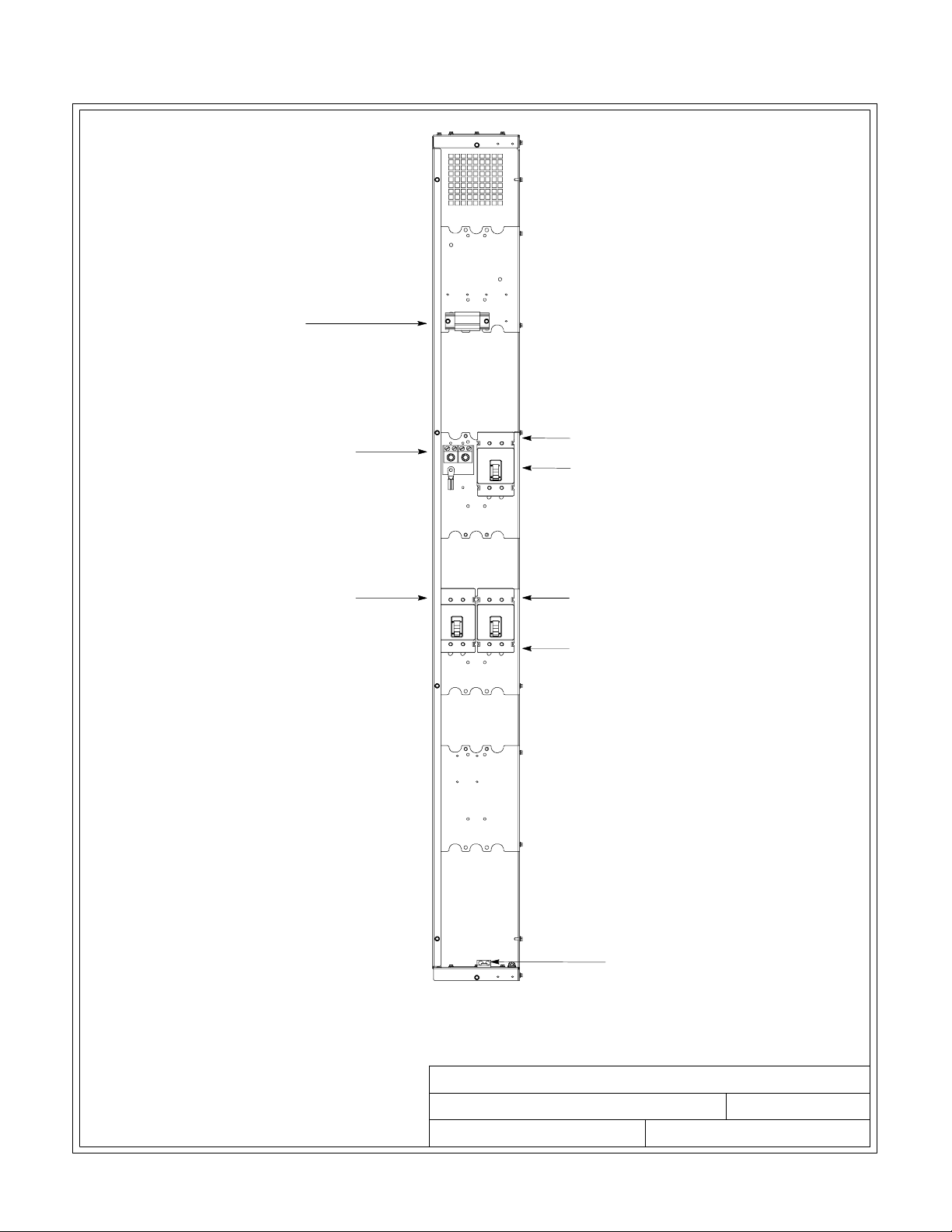
TERMINAL TB1
NEUTRAL
INSTALLATION INFORMATION
AC OUTPUT TO
CRITICAL LOAD
(A,B,C)
(SEE SHEET 30 of 34
FOR DETAILS)
SYSTEM LOAD BREAKER (SLB) (OPTIONAL)
MODULE OUTPUT
BREAKER 1 (MOB 1)
40/20, 40/30, 40/40 KVA 480/480V
MODULE OUTPUT
BREAKER 2 (MOB 2)
AC INPUT FROM UPM 2
(A,B,C)
(SEE SHEET 29 of 34
FOR DETAILS)
GROUND
PARALLEL REDUNDANT CONFIGURATION WITH SLB
NOTE Metal shields covering wiring terminals
must be removed to access terminals.
EATON Powerware®9390 UPS Sidecar Installation and Operation Manual S 164201586 Rev E www.powerware.com
DESCRIPTION:
DRAWING NO: SHEET:
REVISION:
POWER TERMINAL LOCA TIONS
164201546---6
DATE:
092107E
12 of 34
A-41
Page 92

INSTALLATION INFORMATION
TERMINAL TB1
NEUTRAL
AC OUTPUT TO CRITICAL
LOAD WITHOUT SLB
(A,B,C)
(SEE SHEET 31 of 34
FOR DETAILS)
MODULE OUTPUT
BREAKER 1 (MOB 1)
MODULE OUTPUT
BREAKER 2 (MOB 2)
40/20, 40/30, 40/40 KVA, 208/208V
PARALLEL REDUNDANT CONFIGURATION
AC INPUT FROM UPM 2
(A,B,C)
(SEE SHEET 31 of 34
FOR DETAILS)
GROUND
A-42
NOTE Metal shields covering wiring terminals
DESCRIPTION:
must be removed to access terminals.
EATON Powerware®9390 UPS Sidecar Installation and Operation Manual S 164201586 Rev E www.powerware.com
DRAWING NO: SHEET:
REVISION:
POWER TERMINAL LOCA TIONS
164201546---6 13 of 34
DATE:
092107E
Page 93

TERMINAL TB1
INSTALLATION INFORMATION
NEUTRAL
AC OUTPUT TO CRITICAL
LOAD WITHOUT SLB
(A,B,C)
(SEE SHEET 31 of 34
FOR DETAILS)
MODULE OUTPUT
BREAKER 1 (MOB 1)
MODULE OUTPUT
BREAKER 2 (MOB 2)
80/40, 80/50, 80/60, 80/80 KVA, 480/480V
PARALLEL REDUNDANT CONFIGURATION
AC INPUT FROM UPM 2
(A,B,C)
(SEE SHEET 31 of 34
FOR DETAILS)
GROUND
NOTE Metal shields covering wiring terminals
must be removed to access terminals.
EATON Powerware®9390 UPS Sidecar Installation and Operation Manual S 164201586 Rev E www.powerware.com
DESCRIPTION:
DRAWING NO: SHEET:
REVISION:
POWER TERMINAL LOCA TIONS
164201546---6 14 of 34
DATE:
092107E
A-43
Page 94
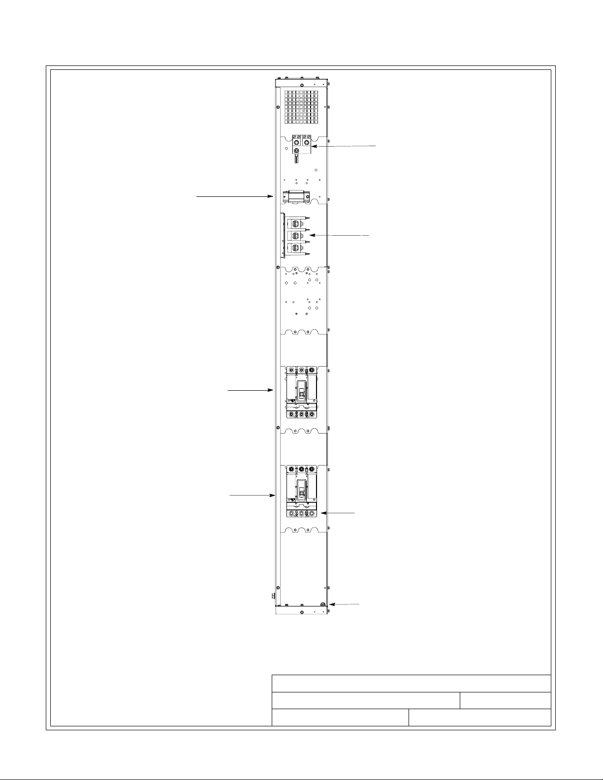
INSTALLATION INFORMATION
NEUTRAL
TERMINAL TB1
AC OUTPUT TO CRITICAL
LOAD WITHOUT SLB
(A,B,C)
(SEE SHEET 32 of 34
FOR DETAILS)
MODULE OUTPUT
BREAKER 1 (MOB 1)
MODULE OUTPUT
BREAKER 2 (MOB 2)
120/100, 120/120 KVA, 480/480V
PARALLEL REDUNDANT CONFIGURATION
AC INPUT FROM UPM 2
(A,B,C)
(SEE SHEET 32 of 34
FOR DETAILS)
GROUND
A-44
NOTE Metal shields covering wiring terminals
DESCRIPTION:
must be removed to access terminals.
EATON Powerware®9390 UPS Sidecar Installation and Operation Manual S 164201586 Rev E www.powerware.com
DRAWING NO: SHEET:
REVISION:
POWER TERMINAL LOCA TIONS
164201546---6 15 of 34
DATE:
063006D
Page 95

TERMINAL TB1
SYSTEM LOAD
BREAKER 1 (SLB 1)
INSTALLATION INFORMATION
NEUTRAL
AC OUTPUT TO
CRITICAL LOAD
(A,B,C)
(SEE SHEET 30 of 34
FOR DETAILS)
MODULE OUTPUT
BREAKER 1 (MOB 1)
MODULE OUTPUT
BREAKER 2 (MOB 2)
40/20, 40/30, 40/40 KVA, 208/208V
PARALLEL REDUNDANT CONFIGURATION W/SLB
NOTE 1. Metal shields covering wiring
terminals must be removed to
access terminals.
2. 80/40 must be wired as 80/50.
AC INPUT FROM UPM 2
(A,B,C)
(SEE SHEET 31 of 34
FOR DETAILS)
GROUND
DESCRIPTION:
DRAWING NO: SHEET:
REVISION:
POWER TERMINAL LOCA TIONS
164201546---6
DATE:
092107E
16 of 34
EATON Powerware®9390 UPS Sidecar Installation and Operation Manual S 164201586 Rev E www.powerware.com
A-45
Page 96

INSTALLATION INFORMATION
TERMINAL TB1
SYSTEM LOAD
BREAKER 1 (SLB 1)
NEUTRAL
AC OUTPUT TO CRITICAL
LOAD WITH SLB
(A,B,C)
(SEE SHEET 30 of 34
FOR DETAILS)
MODULE OUTPUT
BREAKER 1 (MOB 1)
MODULE OUTPUT
BREAKER 2 (MOB 2)
80/40, 80/50, 80/60, 80/80 KVA, 480/480V
PARALLEL REDUNDANT CONFIGURATION W/SLB
NOTE 1. Metal shields covering wiring
terminals must be removed to
access terminals.
2. 80/40 must be wired as 80/50.
AC INPUT FROM UPM 2
(A,B,C)
(SEE SHEET 31 of 34
FOR DETAILS)
GROUND
DESCRIPTION:
DRAWING NO: SHEET:
REVISION:
POWER TERMINAL LOCA TIONS
164201546---6
DATE:
061507E
17 of 34
A-46
EATON Powerware®9390 UPS Sidecar Installation and Operation Manual S 164201586 Rev E www.powerware.com
Page 97

AC OUTPUT TO CRITICAL
LOAD WITHOUT SLB
(A,B,C)
(SEE SHEET 32 of 34
FOR DETAILS)
INSTALLATION INFORMATION
NEUTRAL
TERMINAL TB1
SYSTEM LOAD
BREAKER 1 (SLB 1)
(OPTIONAL)
MODULE OUTPUT
BREAKER 1 (MOB 1)
MODULE OUTPUT
BREAKER 2 (MOB 2)
AC OUTPUT TO CRITICAL
LOAD WITH SLB
(A,B,C)
(SEE SHEET 30 of 34
FOR DETAILS)
AC INPUT FROM UPM 2
(A,B,C)
(SEE SHEET 32 of 34
FOR DETAILS)
120/100, 120/120 KVA, 480/480V
PARALLEL REDUNDANT CONFIGURATION
NOTE 1. Metal shields covering wiring
terminals must be removed to
access terminals.
2. 80/40 must be wired as 80/50.
EATON Powerware®9390 UPS Sidecar Installation and Operation Manual S 164201586 Rev E www.powerware.com
GROUND
DESCRIPTION:
DRAWING NO: SHEET:
REVISION:
POWER TERMINAL LOCA TIONS
164201546---6
DATE:
063006E
18 of 34
A-47
Page 98

INSTALLATION INFORMATION
NEUTRAL
TERMINAL TB1
MODULE OUTPUT
BREAKER 1 (MOB 1)
MODULE OUTPUT
BREAKER 2 (MOB 2)
80/40, 80/50, 80/60, 80/80 KVA, 208/208V AND
160/100, 160/120, 160/160 KVA, 480/480V
PARALLEL REDUNDANT CONFIGURATION
AC OUTPUT TO
CRITICAL LOAD
(A,B,C)
(SEE SHEET 33 of 34
FOR DETAILS)
AC INPUT FROM UPM 2
(A,B,C)
(SEE SHEET 33 of 34
FOR DETAILS)
GROUND
NOTE 1. Metal shields covering wiring
terminals must be removed to
access terminals.
2. 80/40 must be wired as 80/50.
3. 160/100 must be wired as 160/120.
A-48
EATON Powerware®9390 UPS Sidecar Installation and Operation Manual S 164201586 Rev E www.powerware.com
DESCRIPTION:
DRAWING NO: SHEET:
REVISION:
POWER TERMINAL LOCA TIONS
164201546---6
DATE:
063006D
19 of 34
Page 99

SYSTEM LOAD
BREAKER (SLB) (OPTIONAL)
INSTALLATION INFORMATION
NEUTRAL
TERMINAL TB1
AC OUTPUT TO
CRITICAL LOAD
(A,B,C)
(SEE SHEET 34 of 34
FOR DETAILS)
MODULE OUTPUT
BREAKER 1 (MOB 1)
MODULE OUTPUT
BREAKER 2 (MOB 2)
80/40, 80/50, 80/60, 80/80 KVA, 208/208V AND
160/100, 160/120, 160/160 KVA, 480/480V
PARALLEL REDUNDANT CONFIGURATION WITH SLB
NOTE 1. Metal shields covering wiring
terminals must be removed to
access terminals.
2. 80/40 must be wired as 80/50.
3. 160/100 must be wired as 160/120.
AC INPUT FROM UPM 2
(A,B,C)
(SEE SHEET 33 of 34
FOR DETAILS)
GROUND
DESCRIPTION:
DRAWING NO: SHEET:
REVISION:
POWER TERMINAL LOCA TIONS
164201546---6
DATE:
063006D
20 of 34
EATON Powerware®9390 UPS Sidecar Installation and Operation Manual S 164201586 Rev E www.powerware.com
A-49
Page 100

INSTALLATION INFORMATION
40/20, 40/30, 40/40 KVA, 480/480V UPS SIDECAR
MAINTENANCE BYPASS CONFIGURATION
INPUT AND LOAD OUTPUT TERMINAL DETAIL
PHASE A
PHASE B
PHASE C
BYPASS
INPUT
TERMINAL
BLOCK
AC INPUT
TO BYP ASS
A-50
AC OUTPUT
TERMINAL
BLOCK
AC OUTPUT
TO CRITICAL
LOAD
EATON Powerware®9390 UPS Sidecar Installation and Operation Manual S 164201586 Rev E www.powerware.com
PHASE A
PHASE B
PHASE C
DESCRIPTION:
DRAWING NO: SHEET:
REVISION:
POWER TERMINAL LOCA TIONS
164201546---6
DATE:
21 of 34
092107D
 Loading...