

Page 1
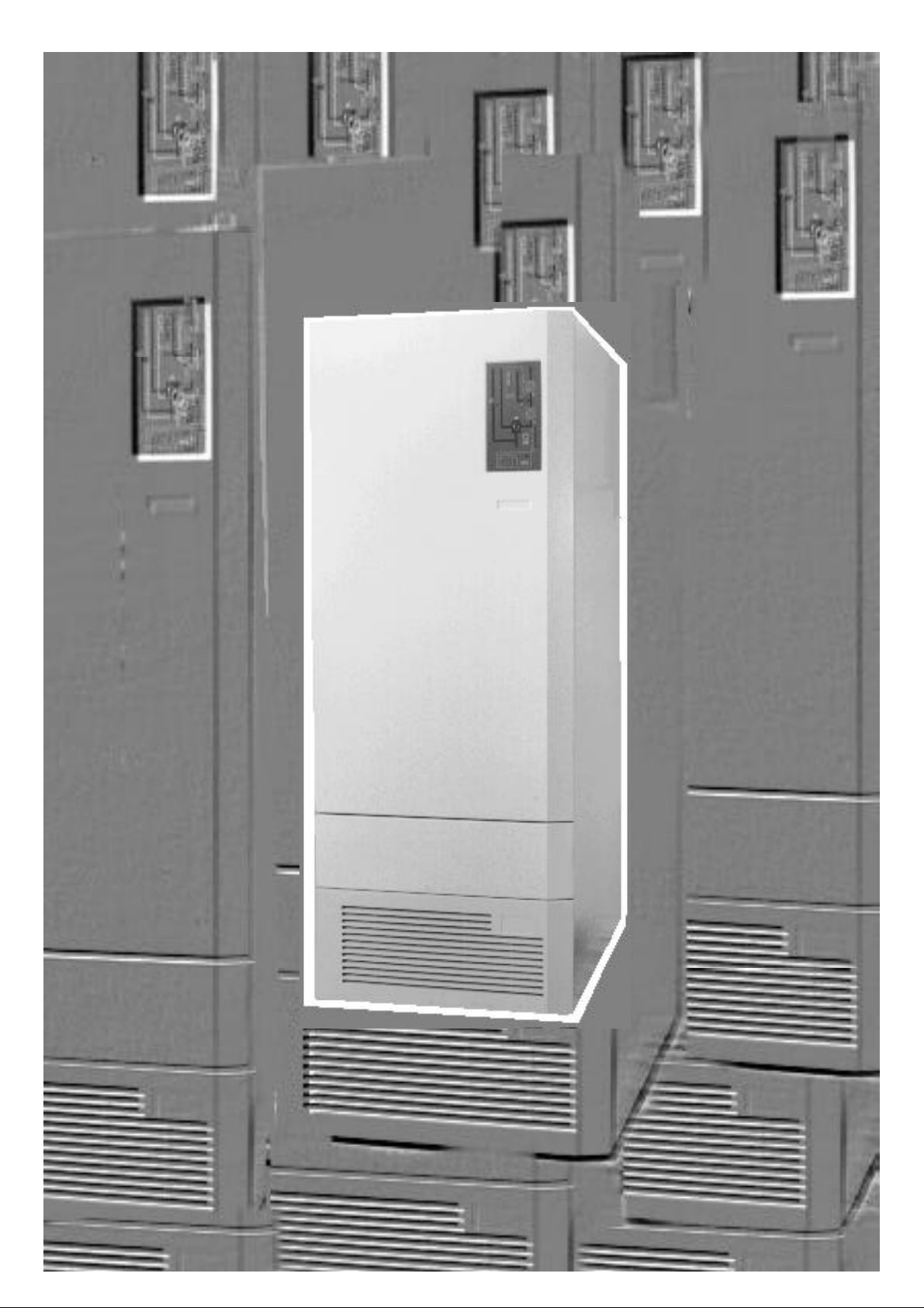
Uninterruptible Power Supply
SOLA 4000
OPERATING MANUAL
JUE 401263
Page 2
Contents of JUE 401263
SOLA 4000 Operating Manual
The SOLA 4000 Operating Manual consists of the following documents:
SECTION 0: JUE 401263 INDEX AND SAFETY INSTRUCTIONS
SECTION 1: JUE 401264 GENERAL SYSTEM DESCRIPTION
SECTION 2: JUE 401265 INSTALLATION AND INITIAL START-UP
SECTION 3: JUE 401266 OPERATION
SECTION 4: JUE 401267 OPERATING PANEL
SECTION 5: JUE 401268 PCB DESCRIPTION
SECTION 6: JUE 401269 TECHNICAL DATA
We reserve the right to modify the contents of this document without notice. BEST POWER- BORRI ELETTRONICA INDUSTRIALE S.r.l Via 8 Marzo Soci, Bibbiena (AREZZO)
ISSUED
See Rev. Doc. JSE401440A
04.02.97
20.06.97
T. Boon
T. Boon
04.02.97M. Porpora
A4 31
JUE 401263
Page 3
3
SOLA 4000 - Operating Manual
Safety Instructions
SAFETY INSTRUCTIONS
The unit must be used as intended. Follow the instructions given in
the Operating Manual.
Dangerous voltages are present inside the unit.
Installation and use of this equipment must comply to all national
and local regulations and procedures.
To prevent overheating do not obstruct the flow of air for ventilation openings to the unit.
The components inside the unit are not repairable by the user. The
user must not open the UPS cabinet or auxiliary cabinets or remove any protective covers from inside the UPS cabinet.
This equipment must be installed and serviced by qualified personnel.
The unit contains Lead-Acid batteries which must be disposed of
correctly, in compliance with the local regulations.
To completely isolate the equipment, the switches IRP, IRE,
IBY,IUG and IB must be switched off, the input supply and the
battery supply must be isolated from the UPS and the output
isolated from other modules if the unit is part of a multi-module
system. For 10-30kVA units with an internal battery, intermediate
links must be removed in order to isolate the battery in sections of
a safe working voltage.
High leakage current: connect protective earth before power
supply cables.
JUE 401263
Page 4
4
SOLA 4000 - Operating Manual
Safety Instructions
Earth leakage protection: this device has a high leakage current
towards protective earthing. The maximum earth leakage current is
300 mA. When setting the threshold of the earth leakage circuit
breaker installed upstream from this equipment consider this
amount of current and that due to the loads.
All primary power switches installed downstream of the UPS must
be labelled as follows: "Isolate UPS (Uninterruptible Power Supply)
before working on this circuit.
The unit is provided with the E.P.O. (Emergency Power Off)
function. This function is activated by pressing simultaneously the
two push buttons on the bottom part of the Front Panel. This
function provides UPS disconnection from the load and from the
battery. Dangerous voltages will still be present inside the unit, if a
shunt-trip of the input supply switch is not provided for.
During electrolysis, batteries release hydrogen gas. There is a risk
of an explosion if the amount of hydrogen in the battery room
becomes too high. Ensure appropriate ventilation of the battery
room according to the standard EN50091-1, to prevent the risk of
an explosion.
JUE 401263
Page 5
Contents of JUE 401264
SOLA 4000 - General System Description
Chapters
1 UPS ASSEMBLY 2
1.1 Features 2
1.2 UPS System Structure 3
1.3 Rectifier/Battery Charger 3
1.4 Battery (Accumulator) 4
1.5 Inverter 4
1.6 Static Switches 4
1.7 Maintenance Bypass 6
1.8 Hot-Standby Systems 6
1.9 Parallel-Redundant Systems 7
1.10 Parallel Systems 7
2 OPERATING PANEL 8
2.1 Functional Description 8
Figures
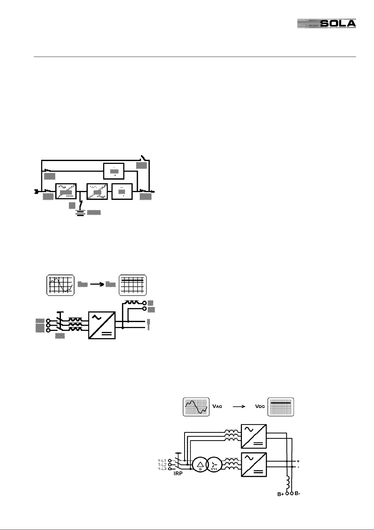
FIG. 1.1 UPS Block-Diagram 3
FIG. 1.2 Rectifier Block-Diagram 3
FIG. 1.3 12-Pulse Rectifier Block-Diagram 3
FIG. 1.4 Inverter Block-Diagram 4
FIG. 1.5 Static Switches Block-Diagram 4
FIG. 1.6 Maintenance Bypass Block-Diagram 6
FIG. 1.6.1 Wall-mounted Maintenance Bypass
Block-Diagram 6
FIG. 1.7 Hot-Standby Operation Block-Diagram
6
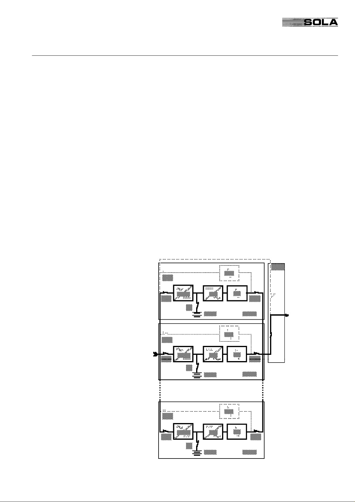
FIG. 1.8 Parallel Operation Block-Diagram 7
FIG. 2.1 SOLA 4000 Operating Panel 8
2.2 Remote Monitoring 8
2.3 Emergency Power Off 8
We reserve the right to modify the contents of this document without notice. BEST POWER- BORRI ELETTRONICA INDUSTRIALE S.r.l Via 8 Marzo Soci, Bibbiena (AREZZO)
ISSUED
See Rev. Doc. JSE401440A 20.06.97 T. Boon
04.02.97
T. Boon
04.02.97M. Porpora
A4 81
JUE 401264
Page 6

SOLA 4000 - General System Description
JUE 401264
1 UPS Assembly
1 UPS ASSEMBLY
1.1 Features
CE This equipment complies to the essential requirements of Euro-
pean Directives 89/336/EEC and 73/23/EEC, and complies to
EN50091-2 (1995) and EN50091-1 (1991) standards.
UPS Function The uninterruptible power supply (UPS) is connected between the
consumer's critical equipment (the load) and supply mains. Its
function is to guarantee a continuous and conditioned power supply
to the load. Even in the case of a total blackout it will supply the
load for a predetermined time (autonomy time). In addition, the
UPS provides the following advantages in comparison with conventional supply systems (mains, motor generator sets, etc.):
Better Output Power Characteristics The UPS output voltage control of frequency and amplitude guar-
antees consistent and stabilised output power. Mains voltage
fluctuations and frequency changes that are usually present in
electricity supply systems do not affect the UPS output voltage.
Uncoupling from Mains Distortion By using double energy conversion from ac to dc and back to ac
and using an isolation transformer in the inverter output, all mains
distortions are filtered out. Therefore, all loads connected to the
UPS system are protected against mains disturbances that can be
present in industrial electricity supply systems. This is especially
important for sensitive electronic devices, e.g. computer systems,
control systems, medical equipment.
Complete Protection against
Mains Failures
During long term or short term ac mains supply interruption, the
UPS system guarantees continuous supply to the connected loads
by means of a battery. The battery is connected to the rectifier
output and the inverter input of the UPS system. In normal operation the inverter (which feeds the load) is fed by the rectifier. In
case of a mains failure, the connected battery automatically feeds
the inverter. Thus the load is supplied without interruption. However, the load can only be supplied by the battery for a certain time
(autonomy time, see chapter 1.4 "Battery"). If longer autonomy
times are required, we recommend the use of a Diesel Generator
Set. In this case the battery autonomy time only has to be sufficient
for the time span between mains failure and full operating capacity
of the Diesel-Generator-Set.
This is a class A product.
In a domestic environment, this product may cause radio
interference, in which case, the user may be required to take
additional measures.
Page 7
SOLA 4000 - General System Description
JUE 401264
1 UPS Assembly
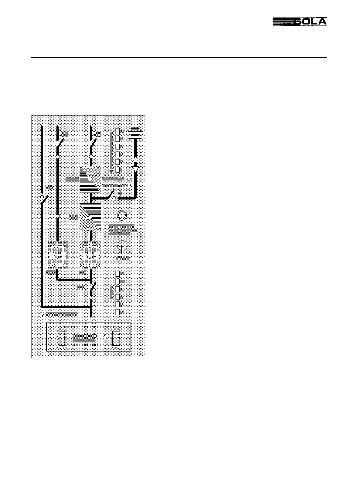
1.2 UPS System Structure
The basic SOLA 4000 power supply unit is an ac/dc/ac converter;
the block diagram: Figure 1.1 illustrates six essential functional
components:
• Rectifier/battery charger (6 pulse) (RECT.)
• Battery (BATT.)
• Inverter (INV.)
• Static inverter switch (SSI)
• Static bypass (SSB)
• Maintenance bypass (IBY)
All components are located in a single housing. They are explained
in detail on the following pages.The control electronics of the
rectifier, inverter and static bypass sections are completely independent of each other. i.e. a failure in any one section will not
cause a failure in another section.
1.3 Rectifier/Battery Charger
In the standard configuration the charger is a three phase/6 pulse
rectifier that converts ac voltage to dc voltage. No isolation transformer is used and the rectifier is connected to the mains via the
commutation chokes which reduce the mains distortion created by
the rectifier. The dc output of the rectifier feeds the inverter and the
battery. The battery is connected to the rectifier through a saturation choke which reduces ac ripple current to the battery, thus
ensuring the maximum battery life-time.
The rectifier is designed to feed both the inverter at maximum load
conditions and simultaneously the battery with maximum charging
current. Normally, the battery voltage is constantly regulated at 432
V dc (floating charge, maintenance-free lead battery, 2.25 volts per
cell). The rectifier's recharge characteristic is of the I/U type. This
means that the recharging current limitation is accomplished by
reduction of the dc voltage, thus assuring that the batteries will not
be damaged by excessive charging currents.
A 12-pulse rectifier is optional and requires the addition of a second rectifier bridge inside the UPS cabinet and a phase shifting
transformer in a separate cabinet.
FIG. 1.3 - 12-pulse Rectifier Block-Diagram
Page 8

SOLA 4000 - General System Description
JUE 401264
1.4 Battery (Accumulator)
The battery supplies power in case of a short interruption or a total
breakdown of the ac mains supply. In case of a rectifier failure (no
dc voltage output), the load will be fed by the battery.
The battery is only capable of feeding the load for a certain time
(autonomy time), depending on battery capacity and actual load.
The number of cells within the battery depends on the battery type
and may also vary due to specific customer requirements. The
standard number is 192 cells for lead-acid batteries and 300 cells
for NiCd batteries. The battery capacity (Ah) depends on the UPS
output power and the required autonomy time. The battery of 1030kVA units is installed inside the UPS cabinet as standard. For
40-120kVA units (or 10-30kVA units with extended battery autonomy), batteries are installed in external battery cabinets.
1.5 Inverter
The inverter converts dc voltage supplied by the rectifier or battery
to ac voltage of a precisely stabilised amplitude and frequency that
is suitable for power supply to most sophisticated electrical equipment.
The inverter output voltage is generated by sinusoidal pulse width
modulation (PWM). The use of a high carrier frequency for the
PWM and a dedicated ac filter circuit consisting of the transformer
and capacitors, ensure a very low distortion of the output voltage
(THD<1% on linear loads).
Every phase voltage of the inverter output is controlled separately,
thus ensuring constant and equal UPS output voltages even with
highly unbalanced loads.
The inverter is designed specifically for the application of today's
loads i.e. The output harmonic distortion will be maintained at low
levels due to a unique adaptive correction technique, even with the
application of highly distorted loads.
The inverter control logic restricts the maximum output current to
150% of the nominal current in case of a short circuit. In case of
overload (up to 125% of the nominal current), the output voltage is
maintained constant. For higher currents the output voltage is
reduced, however, this will only occur if the bypass supply is not
available. Otherwise the UPS will switch to bypass operation for
currents higher than 110% of the nominal current.
The inverter IGBT transistors are fully protected from severe short
circuits by means of a desaturation monitor or "electronic fuse".
1 UPS Assembly
1.6 Static Switches
The block diagram illustrates the two static switch sections that use
thyristors as switching elements. During normal UPS operation,
SSI is closed and SSB is open, thus connecting the load to the
inverter output.
Page 9

SOLA 4000 - General System Description
JUE 401264
1 UPS Assembly
During overload or inverter failure conditions, SSI is switched off
and SSB is switched on, providing power supply from a backup
source (mains, output of another UPS system, diesel generator
set....). By always actuating both switches together for a short
period, an uninterrupted power supply during the switching is
ensured. This is an essential condition to reliably meet all power
supply requirements for connected sensitive equipment.
The control for each static switch (SSB and SSI) is performed
totally independently of each other, thus ensuring that a failure in
one static switch does not affect the other.
Switching Conditions, Inverter - Bypass
The voltage and frequency of the bypass line have to be within
set tolerance limits, and the inverters have to be synchronised
with the bypass line.
Under inverter failure conditions:
(i) the UPS switches to bypass operation, for a single unit. (SSB
switches on, and SSI off).
(ii) for hot-standby units, the load is commutated to the second
inverter, and will switch to bypass only when no inverter is ready to
take the load.
(iii) in parallel systems, all units switch to bypass operation together
only if the load is more than the rated value for the remaining on-line
units.
If the conditions above for the bypass line and synchronisation
are not met:
• the inverter will continue to operate with reduced output voltage
under overload conditions, or
• the inverter will stop if an inverter failure occurs.
In this second case, the system will:
(i) commutate to a second standby-inverter in the case of a hot-
standby system
(ii) the remaining inverters will take the load in the case of a
parallel-redundant system or,
(iii) the UPS will commutate to the bypass supply with a very short
interruption of 10msec if the supplies are not synchronised, for the
case of a single UPS unit.
Under overload conditions, all UPS modules present will
switch to the bypass supply, and remain in bypass until the
overload is removed.
Switching Conditions, Bypass - Inverter a) The UPS switches automatically back to inverter operation
when inverter voltage and frequency are within tolerance limits,
the overload has been removed and the inverter is synchronised with the bypass line (SSI switches on and SSB off).
b) If the UPS unsuccessfully attempts five times within 3 minutes
to switch to inverter operation, the UPS remains in bypass
operation and signals an alarm. After pressing the reset-button
once to reset the audible alarm, it should be pressed a second
time to automatically switch back to inverter operation.
c) If the UPS remains blocked on bypass operation and a mains
failure occurs, the UPS will switch automatically to inverter
operation if the inverter voltage and frequency are within
tolerance and the inverter is synchronised to the mains.
Page 10
SOLA 4000 - General System Description
JUE 401264
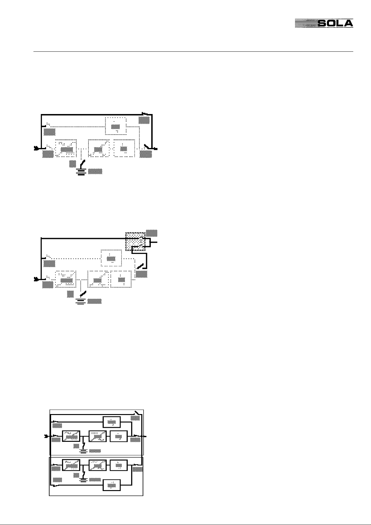
1.7 Maintenance Bypass
The maintenance bypass function is to supply power directly to the
connected load during UPS maintenance. The bypass consists
essentially of one switch IBY.
With SOLA 4000 series UPS systems, switching from different
operating modes to maintenance bypass can be performed without
interruption. With the maintenance bypass on, the UPS system
may be completely switched off, thus permitting maintenance work
to be carried out safely ( there will only be voltage at the input and
output terminals and their connections to the circuit-breakers).
In order to prevent erraneous switching of the maintenance bypass
switch IBY that could possibly cause parallel connection of the
bypass line and the inverter line, IBY is electronically interconnected with the static inverter switch SSI. Thus, during actuation of
IBY, switch SSB will be closed and switch SSI opened automatically, preventing parallel operation of the maintenance bypass
network and the inverter.
1 UPS Assembly
As an option, an external wall-mounted no-break maintenance
bypass switch (see FIG. 1.6.1) may be supplied by SOLA.This
switch provides simple one-step transfer to maintenance bypass
(version 1) without the possibility of erraneous switching and
without interruption to the load.For the version 2 type maintenance
bypass, an additional position is provided in order to completely
isolate the UPS with the one bypass switch.In this way, the UPS
may be isolated totally from all supply by switching off the input
supply to the UPS.
1.8 Hot-Standby Systems
A hot-standby UPS system basically consists of two (or more)
single UPS units which operate independently of each other. Any
one unit can be feeding the load at any time.
• All units are continuously in operation; but only one is supplying
the load, at any one time.
• In case of a failure in the unit currently supplying the load,
another unit is ready to takeover the load without an interruption on the output side. i.e. the load is still supplied with conditioned and stabilised power.
• The load is supplied by the static bypass, only if there is no
inverter ready in the system to takeover the load.
Page 11
SOLA 4000 - General System Description
JUE 401264
1 UPS Assembly
1.9 Parallel-Redundant Systems
A parallel UPS system consists of 2 to 8 single UPS units connected in parallel, sharing the load current equally. Each unit has an
individual static bypass, thus ensuring also redundancy of the static
bypasses in a redundant system, i.e. if one static bypass should fail,
the bypass system will still be available.
There is no common electronic device for the parallel system. Each
unit has its own parallel-operation electronics that controls all of its
functions, thus ensuring perfect redundancy.
1.10 Parallel Systems
This is identical to the configuration in section 1.9 except that the
rated load is normally equal to the rating of the UPS and there is
therefore no redundant unit. UPS units of different kVA ratings may
be connected in parallel in this configuration, proportionally sharing
the load.
Note that the parallel configuration is identical to the parallelredundant configuration if the load is reduced to a value such that
the system minus one (or more) units is capable of supplying the
reduced load. Therefore one (or more) units become redundant and
the control is identical.
FIG. 1.8 - Parallel Operation - Block Diagram
Page 12
SOLA 4000 - General System Description
JUE 401264
2 OPERATING PANEL
2.1 Functional Description
The operating panel is the user-interface of the UPS. It offers the
following functions:
• Indication of important data (actual load, battery charging
status, battery autonomy during the "BACK UP" phase)
• Protective functions ( Battery Running Down, Battery Test)
• Indication of the UPS operating mode
• Alarm signalling (audible and visual)
• Start push button
• Reset function after retransfer blocked condition
• Emergency-Power-Off function
The panel can be subdivided in four functional sections:
1. Block diagram with status LEDs
2. Battery autonomy and charging status
3. Percentage of load supplied
4. E.P.O. push-button
2 Operating Panel
2.2 Remote Monitoring
The operating panel provides an option to communicate with a
computer through RS232 and RS485 interfaces. The RS232 serial
interface communicates with a PC or mainframe computer, with a
SNMP protocol (SEC). With the RS485 interface it is possible to
transmit all necessary data up to a distance of 400m or to connect
a remote monitoring panel.
2.3 Emergency Power Off
In case of emergency it is possible to switch off the entire UPS
system. This is done by simultaneously pressing the "Emergency
Power Off" (E.P.O.) push-buttons located on the operating panel.
This function provides UPS disconnection from the load and the
battery, when a separate shunt-trip battery circuit breaker is installed.
In the case of parallel and hot-standby configurations, activating
E.P.O on one unit, automatically switches OFF the entire system
(when IUG is closed on that unit).
Page 13
Contents of JUE 401265
SOLA 4000 - Installation and Initial Start-Up
Chapters
1 INSTALLATION 3
1.1 Mechanical Installation 3
1.2 Electrical Installation 8
1.3 Install. of Additional Optional Cabinets 13
1.4 Installation of an External Maintenance
Bypass 16
1.5 CPNET Interface Card 18
1.6 Remote Emergency Power off 20
1.7 Diesel - Generator Operation 21
1.8 Common Alarm Contacts 22
1.9 Remote Reset 22
1.10 Installation of Hot-Standby Systems 23
1.10.1Installation of the Interconnection Cable 25
1.11 Installation of Parallel Systems 26
1.11.1Installation of the Interconnection Cable 29
1.12 Battery Installation 30
1.12.1Installation of the Internal Batteries SOLA
4000 10-30kVA 30
1.12.2Installation of External Batteries 32
Figures
FIG.1.1.1 Moving the UPS 10-60kVA units 3
FIG.1.1.2 10-60kVA UPS floor space 4
FIG.1.1.3 80-120kVA UPS floor space 4
FIG.1.1.4 AC001 transformer cabinet 4
FIG.1.1.5 AC002 transformer cabinet 4
FIG.1.1.6 10-60kVA UPS room size 5
FIG.1.1.7 80-120kVA UPS room size 6
FIG.1.1.8 80-120kVA UPS room size 7
FIG.1.2.1 UPS connection diagram, version 1 9
FIG.1.2.2 UPS connection diagram, version 2 11
FIG.1.3.1 UPS connection diagram, with input
and output transformers 13
FIG.1.3.2 UPS connection diagram, with bypass
input transformer 13
FIG.1.3.3 UPS connection diagram, with THD
filters 14
FIG.1.3.4 Installation of 12-pulse units without
galvanic isolation 15
FIG.1.3.5 Installation of 12-pulse units with
galvanic isolation 15
2 INITIAL START- UP 38
2.1 Start-Up Procedure 38
3 ADDITIONAL START- UP
PROCEDURE FOR MULTI-UNIT
SYSTEMS 42
3.1 Start-Up Procedure for
Hot-standby Systems 42
3.2 Start-Up Procedure
for Parallel Systems 43
We reserve the right to modify the contents of this document without notice. BEST POWER- BORRI ELETTRONICA INDUSTRIALE S.r.l Via 8 Marzo Soci, Bibbiena (AREZZO)
ISSUED
See Rev. Doc. JSE401479B08.08.97
See Rev. Doc. JSE401490
C
See Rev. Doc. JSE401547D23.09.97 T. Boon
04.02.97
01.09.97
M. Porpora
M. Porpora
FIG.1.4.1 External maintenance bypass switch,
version 1 16
FIG.1.4.2 External maintenance bypass switch,
version 2 17
FIG.1.6.1 Connection of remote EPO with N.C.
contact 20
FIG.1.6.2 Connection of remote EPO witn N.O.
contact 20
FIG.1.6.3 Connection of remote emergency
power off - input and battery circuit
breaker trip circuit 20
FIG.1.7.1 Connection for diesel generator
operation - syncronisation disable 21
FIG.1.7.2 Connection for diesel generator
operation - second level current
limitation 21
M. Porpora
T. Boon
04.02.97
A4 441
JUE 401265
Page 14

SOLA 4000 - Installation and Initial Start-Up
SOLA 4000 - Installation and Initial Start-Up
FIG.1.8.1 Connec. of remote common alarm 22
Figures
FIG.1.9.1 Connection of remote reset 22
FIG.1.10.1Interconnection of hot-standby units
with integrated maintenance bypasses
and separate bypass terminals 23
FIG.1.10.2Interconnection of hot-standby units
with external maintenance bypass and
separate bypass terminals. 24
FIG.1.10.3Interconnection of control BUS cable
for hot-standby units 25
FIG.1.11.1Interconnection of parallel units with
integrated maintenance bypasses and
separate bypass terminals. 27
FIG.1.11.2Interconnection of parallel units with
common maintenance bypass and
separate bypass terminals 28
FIG.1.11.3Location of connectors on the
IBYBP-CP pcb 29
FIG.1.11.4Interconnection of control BUS cables
between parallel units 29
FIG.1.12.1Internal battery connections 31
FIG.1.12.2B3/38: battery tray in the first level 32
FIG.1.12.3B3/38: batt. trays in the second and the
third level 32
FIG.1.12.4Battery cabinet B3/38 32
FIG.1.12.5B3/38:switch IB and terminals 33
FIG.1.12.6B3/38 internal electrical connec. 34
FIG.1.12.7Battery cabinet B3/65 35
FIG.1.12.8B3/65:switch IB and terminals 35
FIG.1.12.9B3/65 internal electrical connec. 36
FIG.1.12.10UPS with additional batt. cabinet 37
Page 15
SOLA 4000 - Installation and Initial Start-Up
1 Installation
1 INSTALLATION
1.1 Mechanical Installation
Equipment Delivery and Storage After delivery, check equipment for any damage that may have
occurred during shipment. The shipper and your SOLA agency
must be notified in writing about damages due to shipment, including a detailed description of visual defects. If you do not wish to
install the equipment immediately, please observe the following
storage recommendations:
• Store equipment in a vertical position in a well conditioned
room, protected against humidity. Do not store the equipment
in close proximity to frequently used passageways and keep it
away from movable parts.
• If the UPS system is already unpacked, please ensure storage
in a clean environment protected from dust, away from heat
sources.
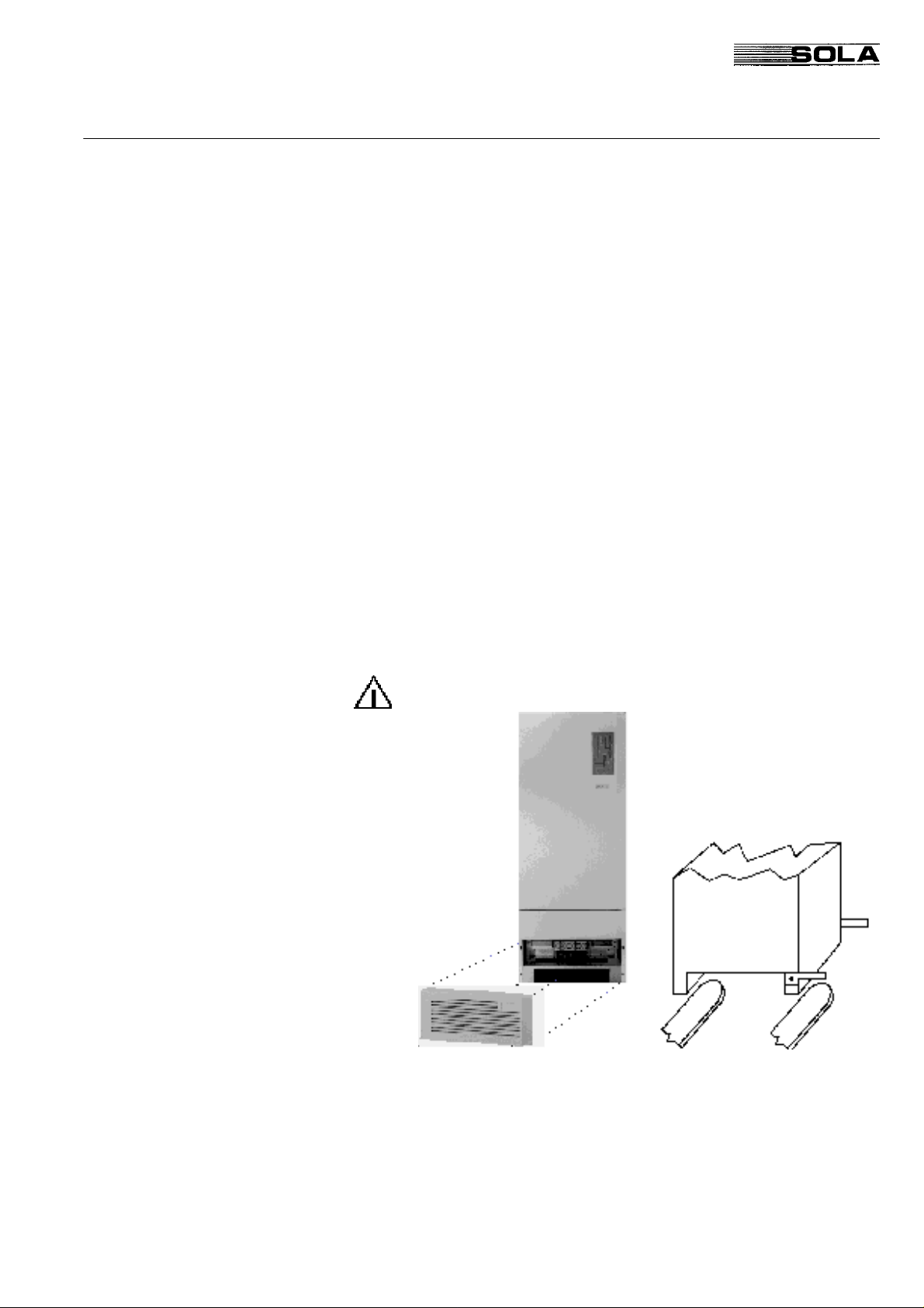
Handling the UPS System The UPS can be simply lifted and moved by means of a lifting
truck or a fork lifter for 80-120kVA units. For 10-60kVA units,
remove the front side and rear side base sheets and attach two
angle irons with 8MA bolts to the right front and rear side of the
UPS. The UPS can now be moved with a lifting fork. Remove the
angle irons when the UPS is set in the correct position.
Caution: Secure equipment against being knocked over
Setting Up The UPS system should be installed in a dry, clean and lockable
room. Provisions have to be made to remove heat created by the
system. Under all installation conditions, the unrestricted flow of
cooling air must be assured.
Page 16
SOLA 4000 - Installation and Initial Start-Up
Weight
1 Installation
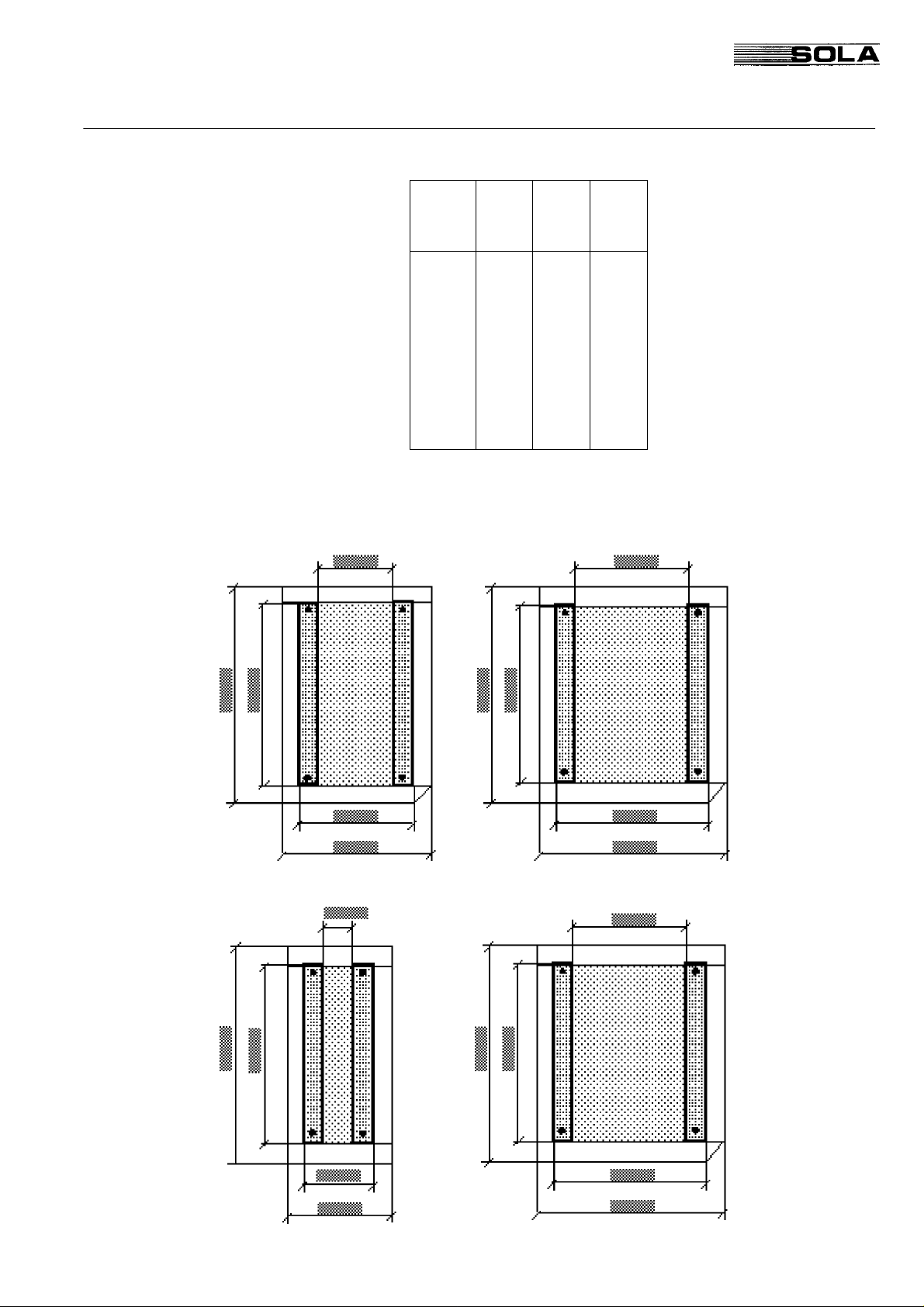
Floor Space Required
Type
SOLA
4000
100 840 - 1219
120 870 - 1263
TAB. 1.1.1 UPS weight
Weight
without
Battery
[kg]
10 310 597 1277(*)
15 310 597 1277(*)
20 335 622 1330(*)
30 350 637 1362(*)
40 480 - 1026
60 520 - 1112
80 810 - 1176
Weight
with
Battery
[kg]
Static
Load
-
[kg/m²]
FIG. 1.1.2 10-60kVA UPS floor space FIG. 1.1.3 80-120kVA UPS floor space
Page 17
SOLA 4000 - Installation and Initial Start-Up
1 Installation
Room Size for 10-60 kVA UPS
FIG. 1.1.6 UPS 10-60kVA room size
Page 18
SOLA 4000 - Installation and Initial Start-Up
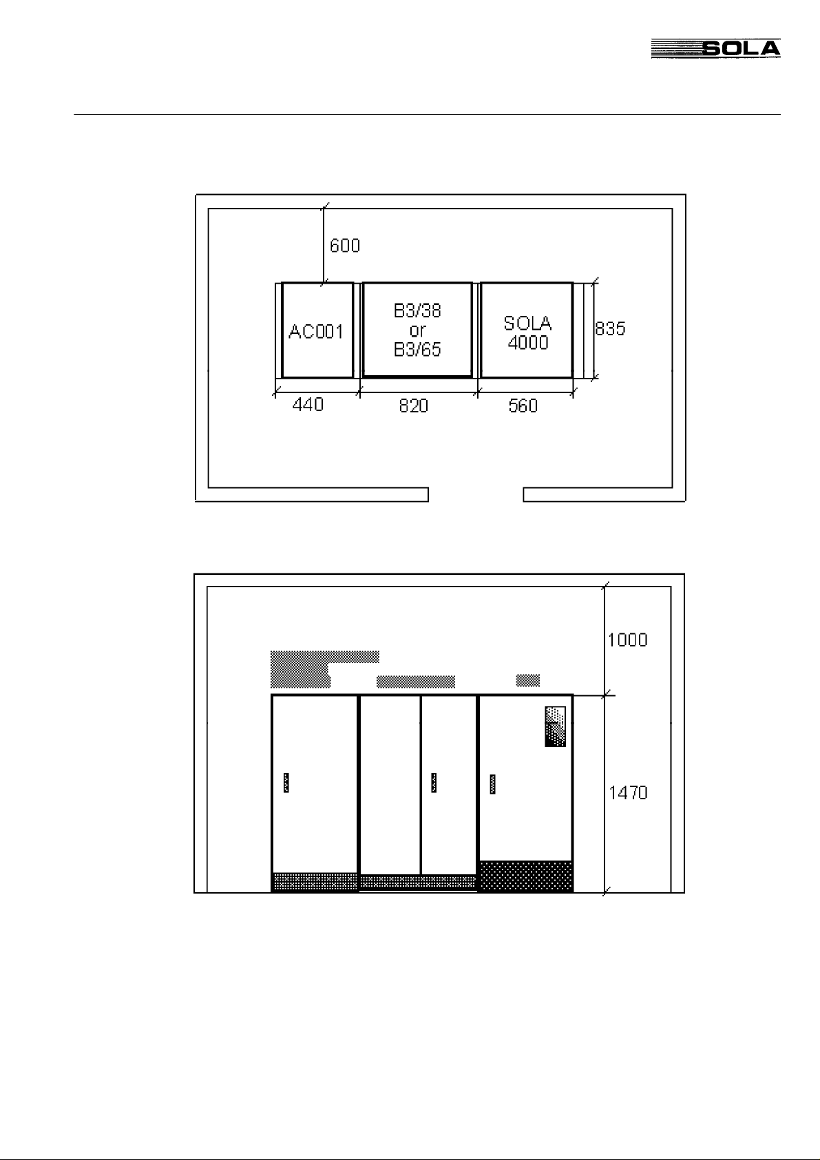
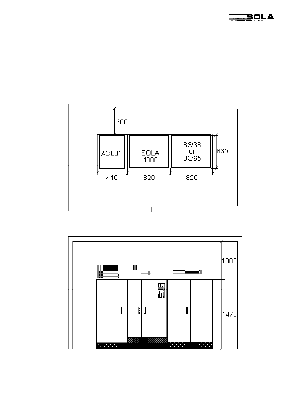
Room Size for 80-120 kVA UPS with
auxiliary AC001 cabinet
AC001 cabinets are used for SOLA 4000 units with 12 pulse
chargers without galvanic separation and with THD Filters.
1 Installation
FIG. 1.1.7 UPS 80-120kVA room size
Page 19
SOLA 4000 - Installation and Initial Start-Up
1 Installation
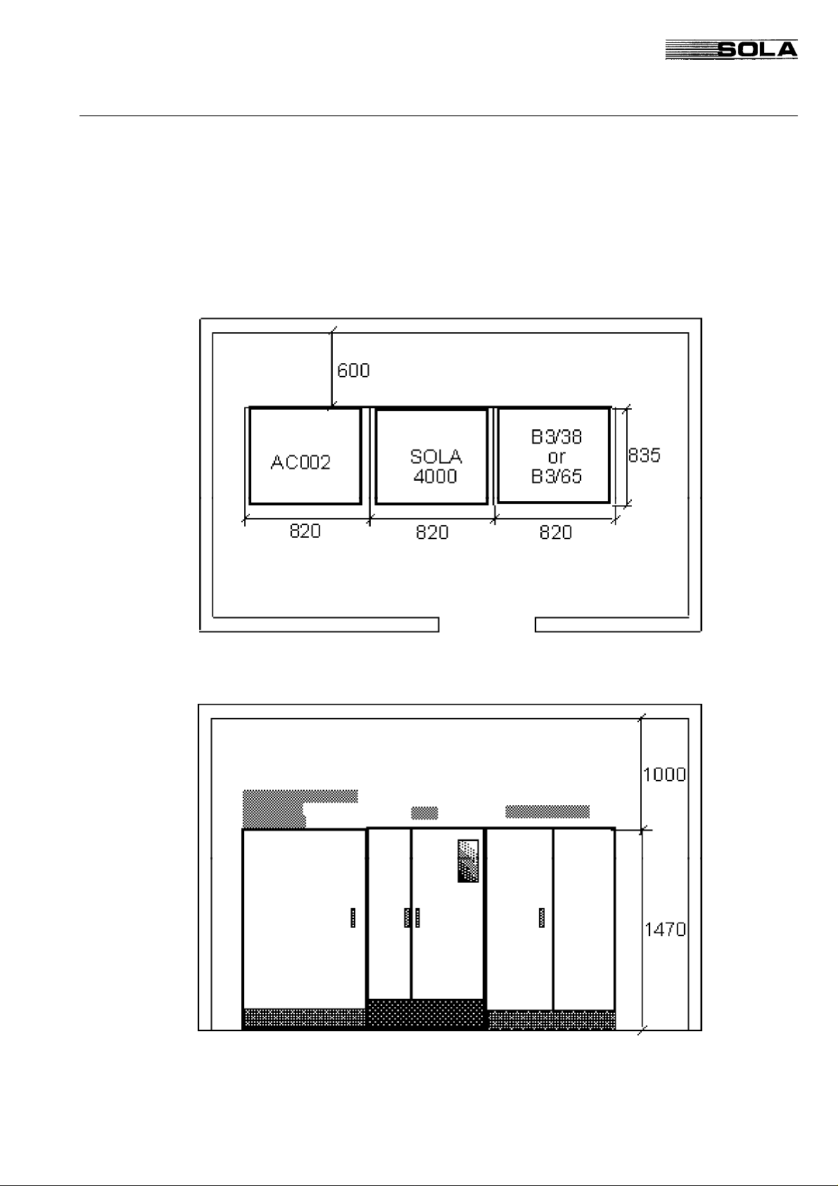
Room Size for 80-120 kVA UPS with
auxiliary AC002 cabinet
AC002 cabinets are used for SOLA 4000 units with 12 pulse
chargers with galvanic separation and with auxiliary transformers.
FIG. 1.1.8 UPS 80-120kVA room size
Page 20
SOLA 4000 - Installation and Initial Start-Up
1.2 Electrical Installation
This equipment must be installed by qualified service personnel.
Switch off IRP, IRE, IB, IUG, IBY circuit breakers to completely
isolate the equipment.
Earth leakage protection: this device has high leakage current
towards protective earthing. Earth leakage circuit breakers
shouldn't be installed upstream from this equipment or a correct
threshold should be set.
High leakage current - it is essential to connect the protective
earth before connecting the power supply.
All primary power switches installed remotely from the UPS area
must be fitted with the following label: "Isolate uninterruptible
power supply (UPS) before working on this circuit".
1 Installation
General
All electrical connections must be made in accordance with local
standards and all input terminals (1-L1, 1-L2, 1-L3 and, if existing,
4-L1, 4-L2, 4-L3) must be protected by external fuses. The tables
give recommended values for fuse sizes and cable cross-sections.
These may vary, depending on local standards. They are valid for
voltages 380/220 V, 400/230 V and 415/240 V. Ensure clockwise
connection of conductors L1, L2 and L3 at input and output terminals.
If possible, install battery cables separately from other power
cables in order to avoid possible RF interference. Before wiring,
open all system switches (IRP, IRE, IBY, IUG) plus the battery
switch (IB).
Page 21
SOLA 4000 - Installation and Initial Start-Up
1 Installation
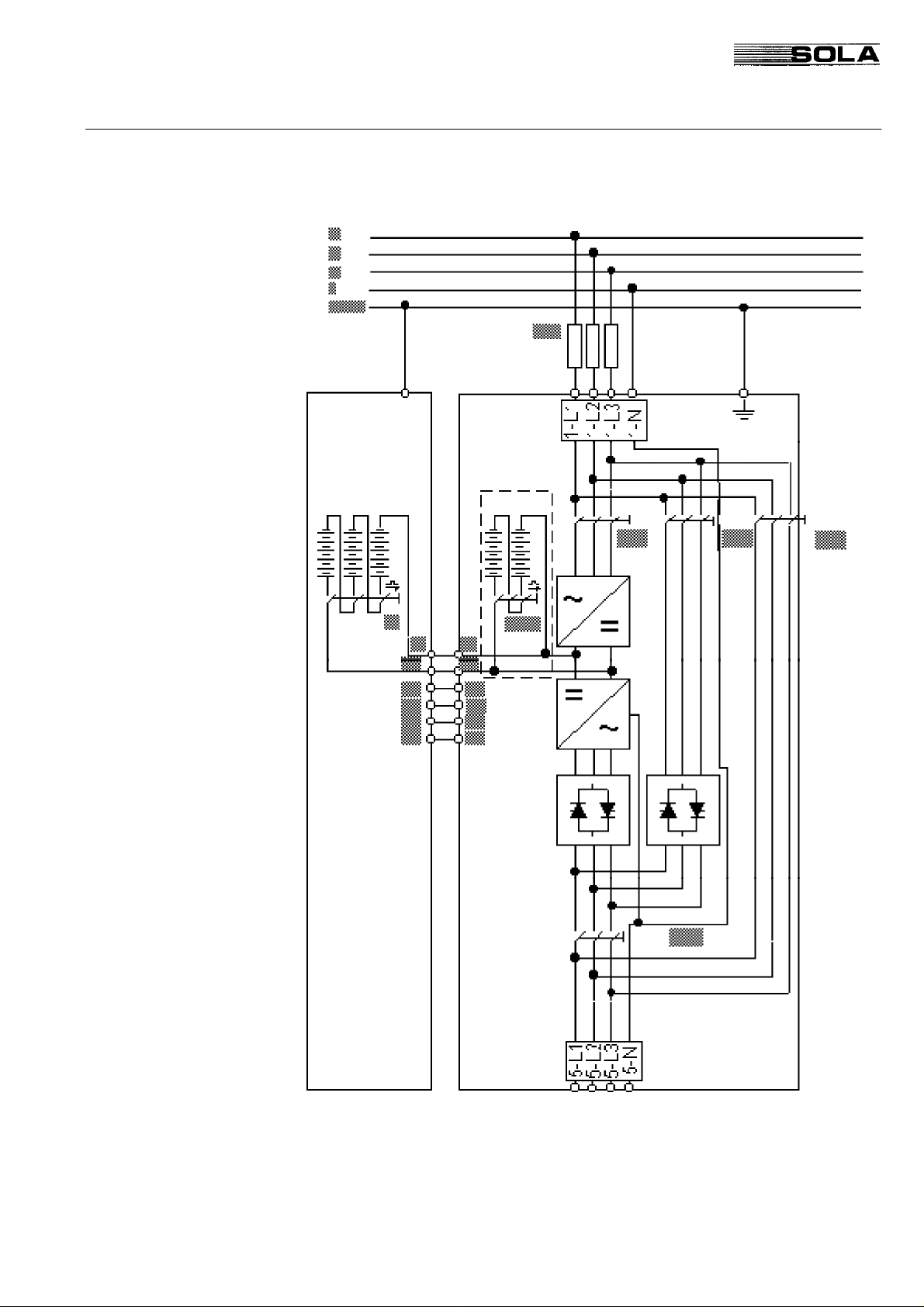
Version 1 SOLA 4000 with Common Input
for Rectifier and Bypass
FIG. 1.2.1 UPS connection diagram, version 1
(*) Note: Internal Battery only for 10-30kVA units
(**) Note: Customer supplied input fuses - see table 1.2.1
Page 22
SOLA 4000 - Installation and Initial Start-Up
Version 1 SOLA 4000 with Common Input for
Input Cables / Fuses
1 Installation
Rectifier and Bypass
Output / Battery Cables and Max. Cur-
rent Ratings for Battery Overcurr. pro-
tection
Type
SOLA
4000
10 4x10 25 16
15 4x10 35 16
20 4x16 50 16
30 4x25 63 25
40 4x35 100 25
60 4x35 125 25
80 4x70 160 50
100 4x70 200 50
120 4x120 250 70
TAB.1.2.1 UPS input cables
and fuses, version 1
Type
SOLA
4000
100 2x95 4x70 250
120 2x120 4 x120 300
Input
cables
[mm²]
Battery
cables
10 2x16 4x10 25
15 2x16 4x10 40
20 2x25 4x16 50
30 2x25 4x35 75
40 2x35 4x25 100
60 2x50 4x35 150
80 2x70 4x50 200
[mm²]
Input
fuses
[A]
Output cables
earth
cable
[mm²]
[mm²]
Max. inv. input
current
(Vdc=320V)
TAB.1.2.2 UPS output cables and fuses, version 1
Page 23
SOLA 4000 - Installation and Initial Start-Up
1 Installation
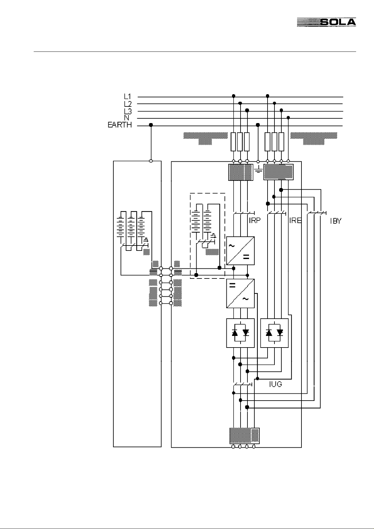
Version 2 SOLA 4000 with Separate Inputs
for Rectifier and Bypass
FIG. 1.2.2 UPS connection diagram, version 2
(*) Note: Internal Battery only for 10-30kVA units
(**) Note: Customer supplied rectifier input fuses - see table 1.2.5
(***) Note: Customer supplied bypass input fuses - see table 1.2.5
Page 24
SOLA 4000 - Installation and Initial Start-Up
Version 2 SOLA 4000 with Separate Inputs
Input Cables
Type
SOLA
4000
10 3x10 4x10 16
15 3x10 4x10 16
20 3x16 4x16 16
30 3x25 4x25 25
40 3x25 4x25 25
60 3x35 4x35 25
80 3x50 4x50 50
100 3x70 4x70 50
120 3x120 4x120 70
Rect.
cables
[mm²]
1 Installation
for Rectifier and Bypass
Bypass
cables
[mm²]
earth
cable
[mm²]
Input Fuses
Output / Battery Cables
TAB. 1.2.3 UPS input cables, version 2
Type
SOLA
Rect.
Fuses
4000
10 25 25
15 35 35
20 50 50
30 63 63
40 100 100
60 100 125
80 125 160
100 160 200
120 200 250
TAB. 1.2.4 UPS input fuses, version 2
Type
SOLA
4000
10 2x16 4x10 25
15 2x16 4x10 40
20 2x25 4x16 50
30 2x25 4x35 75
40 2x35 4x25 100
60 2x50 4x35 150
80 2x70 4x50 200
100 2x95 4x70 250
120 2x120 4 x120 300
Battery
cables
[mm²]
Bypass Fuses
[A]
[A]
Output cables
[mm²]
Max. inv. input
current
(Vdc=320V)
TAB. 1.2.5 UPS output cables and fuses, version 2
Page 25
SOLA 4000 - Installation and Initial Start-Up
1 Installation
1.3 Installation of additional optional cabinets
SOLA 4000 with input and output transformers for voltage adaption
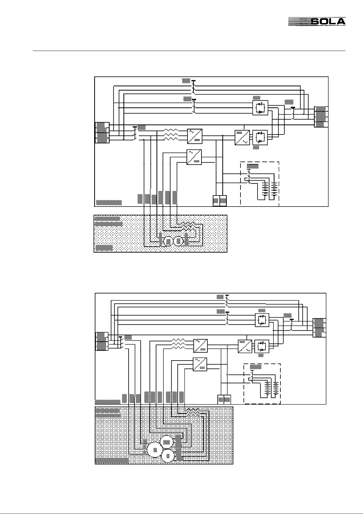
FIG. 1.3.1 UPS connection diagram, with input and output transformers to adapt the
UPS to the on-site voltage.
SOLA 4000 with isolation transformer of the bypass supply
FIG. 1.3.2 UPS connection diagram, with bypass input transformer to isolate the
neutral line (** 4-N may be connected to the supply neutral or earth or left disconnected.)
(*) Note: Internal Battery only for 10-30kVA units
Page 26
SOLA 4000 - Installation and Initial Start-Up
SOLA 4000 with THD filters
1 Installation
FIG. 1.3.3 UPS connection diagram, with THD filters
(*) Note: Internal Battery only for 10-30kVA units
Page 27
SOLA 4000 - Installation and Initial Start-Up
1 Installation
SOLA 4000 with 12-pulse charger / rectifier
FIG. 1.3.4 Installation of 12-pulse units without galvanic isolation
SOLA 4000 with 12-pulse charger / rectifier and galvanic isolation of the input supply.
FIG. 1.3.5 Installation of 12-pulse units with galvanic isolation
(*) Note: Internal Battery only for 10-30kVA units
Page 28
SOLA 4000 - Installation and Initial Start-Up
1.4 Installation of an External Maintenance
Bypass
When an external maintenance bypass is installed, a normally
open, voltage free contact must be available. This contact must be
connected to the connector M4, Pin1 and Pin 2 at the top left hand
corner of the mother board for the inverter/bypass electronics
(IBYBP-CP see figure 1.10.3).
If the standard SOLA no-break wall-mounted maintenance bypass
switch is used (optional) in the MB3 cabinet, a normally open
contact is provided.For the version 2 maintenance bypass (3
position), an additional contact is provided which automatically
isolates the UPS system (EPO) when switched to the "UPS ISOLATED" position (see FIG 1.4.2).
1 Installation
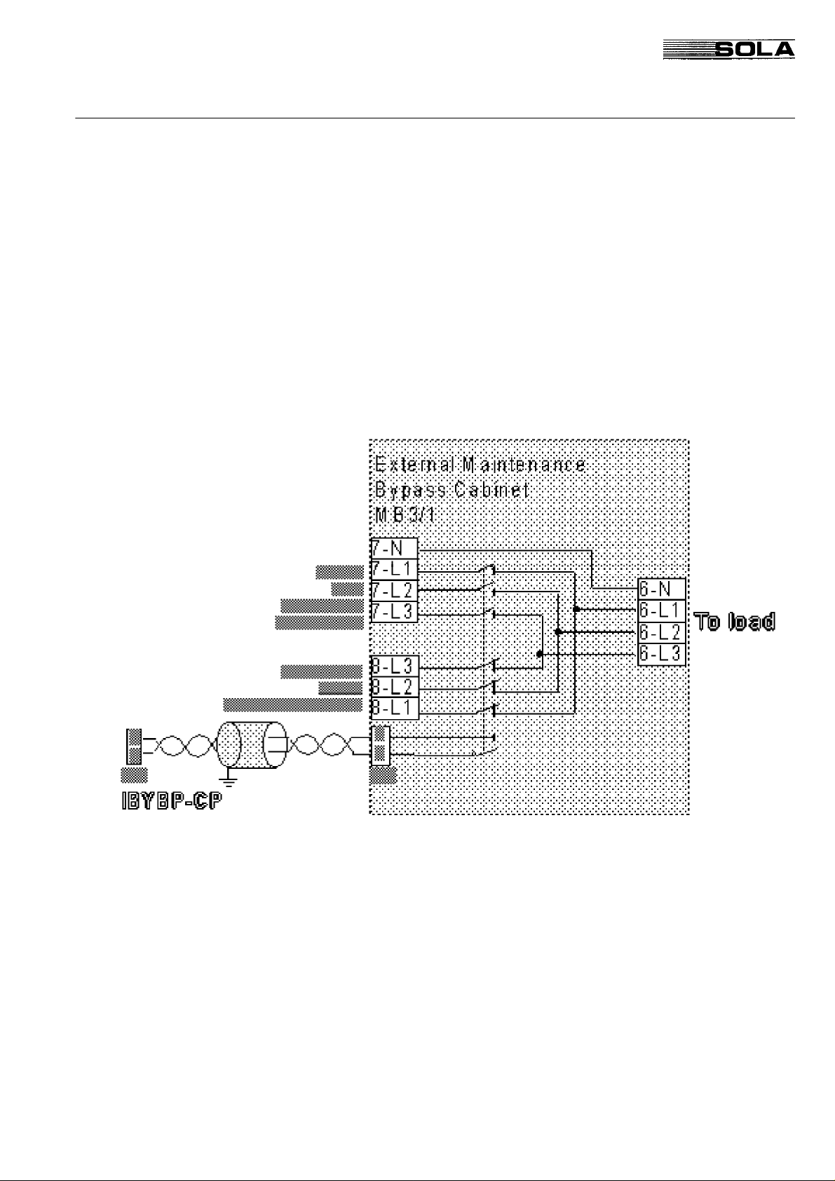
FIG.1.4.1 External Maintenance Bypass Switch Version 1 (2 position)
Page 29
SOLA 4000 - Installation and Initial Start-Up
1 Installation
FIG.1.4.2 External Maintenance Bypass Switch Version 2 (3 position)
Note1: For Hot-Standby or parallel systems, it is sufficient to
feed one contact into one unit only, however they may be
connected in parallel at M4 (of IBYBP-CP) Pin1 and Pin 2 for
all units. In this case separate terminals may be provided
within the MB3 cabinet (see FIG. 1.9.2 and 1.10.2)
Note2: The cable used must be twisted pair, with a total shield.
This shield must be grounded at one end (the cabinet of the
UPS may be used).
Page 30
SOLA 4000 - Installation and Initial Start-Up
1.5 CPNET Interface Card
The CPNET interface card is used for remote signalling of four
standard alarm conditions by means of voltage-free contacts in
programmable configurations.
1.5.1 Installation
The CPNET interface card is a small pcb that is installed directly
underneath the CPU/NCP pcb, inside the front door of the UPS
cabinet.
It is connected to the UPS via the connector CN1 on the CPNET
pcb to CN10 on the CPU/NCP pcb.
It can be connected to remote devices via two different connectors:
• CN2, a 9 pin sub-D connector for standard computer connection. The following interface cables are available (see also
JUE 300 599):
- IBM AS-400
- Novell
- 3-COM
- Banyan Vines
• M1, a terminal block for individual configurations.
1 Installation
1.5.2 Functions
Contacts for the following alarm conditions are available:
Inverter Operation (N) (CN1, pin 6)
Bypass Operation (B) (CN1, pin 8)
Mains Failure (MF) (CN1, pin 5)
Battery Low (BL) (CN1, pin 7)
By means of the DIP switch SW1, the single relays and output pins
can be configured for each requirement.
SW1
1 2 3 4 5 6 7 8
0 0 0 1 0 1 1 0 IBM-AS400
0 0 0 0 - - 0 1 NOVEL
0 0 1 0 - - - - 3-COM
0 0 0 0 - - - - BANYAN-VINES
0 1 1 0 - - 0 1 BORRI VIKING
0 0 1 0 - - 0 1 BORRI SIDEKICK
0 0 1 0 - - 0 1 AMERICAN POWER
INTERFACE
TAB. 1.5.2.1 Programming of the CP-NET pcb
Note: Maximum rating of relay contacts: 250Vac, 6A (only when using
connector M1)
Page 31

SOLA 4000 - Installation and Initial Start-Up
1 Installation
Pin
Pin
CN2
1 1 Not Used
2 2 N - MF* - MF* MF* MF*
3 3 MF MF MF MF MF MF MF
4 4 Common
5 5 BL BL BL BL BL BL BL
6 6 B MOK - - MOK MOK MOK
7 7 BOK BOK BOK BOK BOK BOK BOK
8 8 - - - - BL* - 9 9 0 V
AS400 NOVEL 3-COM BANYAN-VINES
M1
10 Not Used
BORRI
VIKING
BORRI
SIDEKICK
AMERICAN
POWER
TAB. 1.5.2.2 Allocation of the pins for the output connectors CN1 and M1 for the various programming
configurations of TAB. 1.5.2.1
Key to table 1.5.2.2 (when contact is closed with respect to pin 4).
N: Inverter Operation
B: Bypass Operation
MF: Mains Failure
BL: Battery Low
MF*: 0V when mains failure, -12V when mains OK
BL*: -12V when battery low, otherwise +12V
MOK: Mains OK
BOK: Battery not low
Page 32

SOLA 4000 - Installation and Initial Start-Up
1 Installation
1.6 Remote Emergency Power off
A Remote Emergency Power Off may be connected to the system.
The connection terminals are M4 Pin 5 and Pin 6, using a normally-open, voltage-free contact as a pushbutton.(See FIG. 1.6.1.
and FIG 1.6.2.)
FIG. 1.6.1 Connection of Remote EPO with N.C. contact FIG. 1.6.2 Connection of Remote EPO with N.O. contact
Note 1: The cable used must be twisted pair, with a total shield. This
shield must be grounded at one end (the cabinet of the UPS may
be used).
Note 2: For Hot-Standby or parallel systems, it is sufficient to feed
one contact into one unit only, however they may be connected in
parallel at M4 (of IBYBP-CP) Pin5 and Pin 6 for all units (N/O) only
or series for (N/C).
Note 3: To completely isolate the UPS system from all voltage with
the emergency power off (EPO), it is necessary to install trippable
circuit breaker on the input supply (to terminals 1-L1, 1-L2, 1-L3
and 4-L1, 4-L2, 4-L3 and 4-N if installed).
The trip coil is then connected to the terminal M1 on the CPU/NCP
pcb located inside the front door of the cabinet. A normally open or
normally closed voltage-free contact is available.
Note 4: The N.C. contact can only be used for IBYBP-CP
motherboards in rev. 0A and following.
FIG. 1.6.3 Connection of Remote Emergency Power Off - Input and battery circuit
breaker trip circuit.
Nominal Rating of Contacts
125 V
30 V
TAB. 1.6.1 Nominal Rating of contacts for the input breaker trip circuit.
0,5 A 60 W
≅
≅
2 A 60 W
Page 33

SOLA 4000 - Installation and Initial Start-Up
1 Installation
1.7 Diesel - Generator Operation
During diesel generator operation, if the frequency of the dieselgenerator, with UPS and load connected, is unstable, it is advisable
to disconnect the synchronisation of the inverter. This is achieved
with a normally-open, voltage-free contact (which closes during
diesel-generator operation) and is connected to the connector M4
Pin 7 and Pin 8 as follows:
FIG. 1.7.1 Connection for Diesel Generator Operation (connector M4) - synchronisation disable.
Note1: For Hot-Standby or parallel systems, it is sufficient to feed
one contact into one unit only, however they may be connected in
parallel at M4 Pin7 and Pin 8 for all units
If it is necessary to reduce the current supplied by the dieselgenerator, then a second voltage-free contact (again normally
open) is required and must to be connected to the connector M8,
Pin 1 and Pin 2 on the rectifier electronic mother board (RBPHC16)
see FIG.1.7.2
FIG. 1.7.2 Connection for Diesel Generator Operation (connector M8) - second level
current limitation.
Note 1: The cable used in both cases must be twisted pair, with a
total shield.This shield must be grounded at one end (the cabinet
of theUPS may be used).
Note 2: The cable for current limitation must be connected to all units
for parallel or hot-standby units, using separate voltage-free
contacts.
Page 34

SOLA 4000 - Installation and Initial Start-Up
1.8 Common Alarm Contacts
As a standard feature, contacts are provided for a remote common
alarm.The connector is located on the control p.c.b for the front
operating panel (CPU/NCP), located inside the front door of the
UPS.
FIG. 1.8.1 Connection of Remote Common Alarm
Nominal Rating of Contacts
1 Installation
125 V
30 V
TAB. 1.8.1 Nominal Rating of contacts for the common alarm.
Note 1: As an option a pcb CP-NET is available, providing more
contacts, compatible with most common configurations (eg AS400,
Novell etc.)
A Remote panel may also be purchased with identical functions to
the front operating panel.
Note 2: To achieve a single common alarm for parallel or hot-
standby units, the contacts of each unit may be interconnected in
parallel (normally - open) or series (normally - closed).
0,5 A 60 W
≅
≅
2 A 60 W
1.9 Remote Reset
The UPS system may be reset remotely with the connection of
contacts ( a push-button) to the terminal M4 as shown:
FIG.1.9.1 Connection of Remote Reset
Note: The cable used must be twisted pair, with a total shield.
This shield must be grounded at one end (the cabinet of the
UPS may be used).
Page 35

SOLA 4000 - Installation and Initial Start-Up
1 Installation
1.10 Installation of Hot-Standby Systems
For hot-standby systems the units must be connected together as
shown in the FIG. 1.10.1 or FIG. 1.10.2
Note: The installation for each unit must be performed in accordance
to the installation of single units as described in the previous
sections. Additionally to this, the outputs must be connected in
parallel as shown in FIG. 1.10.1 or in FIG.1.10.2
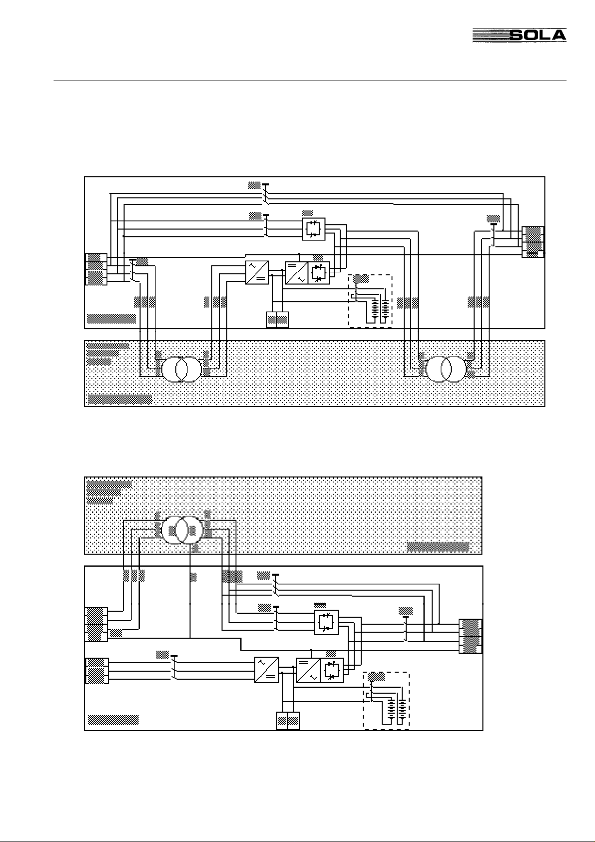
FIG. 1.10.1 Interconnection of hot-standby units with integrated
maintenance bypasses and separate bypass terminals.
(*) Note: Internal Battery only for 10-30kVA units
Page 36

SOLA 4000 - Installation and Initial Start-Up
1 Installation
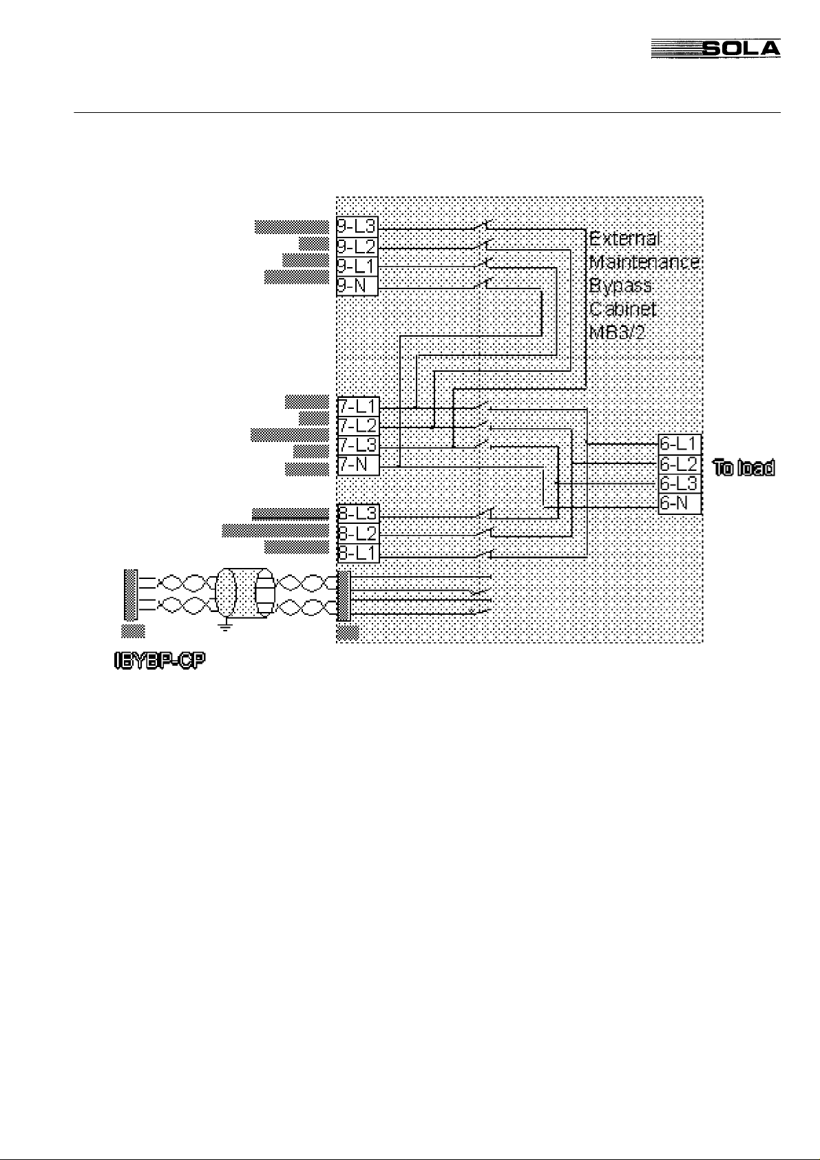
FIG. 1.10.2 Interconnection of hot-standby units with external maintenance bypass and
separate bypass terminals.
(*) Note: The internal maintenance bypass (IBY) may or may not be installed in this con-
figuration.
(**) Note: This cable must be twisted pair, total shield (refer. to section 1.4)
(***) Note: Internal Battery only for 10-30kVA units
Page 37

SOLA 4000 - Installation and Initial Start-Up
1 Installation
1.10.1 Installation of the Interconnection Cable
The supplied cable must be connected between the units within the
system. This must be connected at either of the connectors CN12
or CN13 on the mother-board of the Inverter/Bypass electronics
(IBYBP-CP) and the other end of the cable is connected to either
CN12 or CN13 on the mother-board of the Inverter/Bypass electronics (IBYBP-CP) of the other unit(s).
Note: If the unit is to be added to one already installed stand-alone
unit which has not been previously tested in a hot-standby configuration, the supports and mounting screws to mount the cable to the
p.c.b are supplied with the cable. They must be mounted at both
sides of the selected connector in order to fix the cable securely to
the connector with the supplied screws.
FIG. 1.10.3 Interconnection of control BUS cable for hot-standby units
Page 38

SOLA 4000 - Installation and Initial Start-Up
1.11 Installation of Parallel Systems
Up to a total of 8 units may be installed together in the one parallel
system.
Note: The installation for each unit must be performed in accordance to the installation of single units as described in the previous
sections. Additionally to this, the outputs must be connected in
parallel as shown in FIG. 1.11.1 or in FIG.1.11.2
Care must be taken with the installation of the bypass line and in
particular, that the cables from the point of common coupling of the
input supply to the terminals 1-L1, 1-L2, 1-L3 (or 4-L1, 4-L2, 4-L3,
4-N if an optional separate bypass input is installed), are of equal
length. Likewise, the output cables from the output terminals (5-L1,
5-L2, 5-L3, 5-N) to the point of common coupling on the load side
must be of equal length.
1 Installation
Page 39

SOLA 4000 - Installation and Initial Start-Up
1 Installation
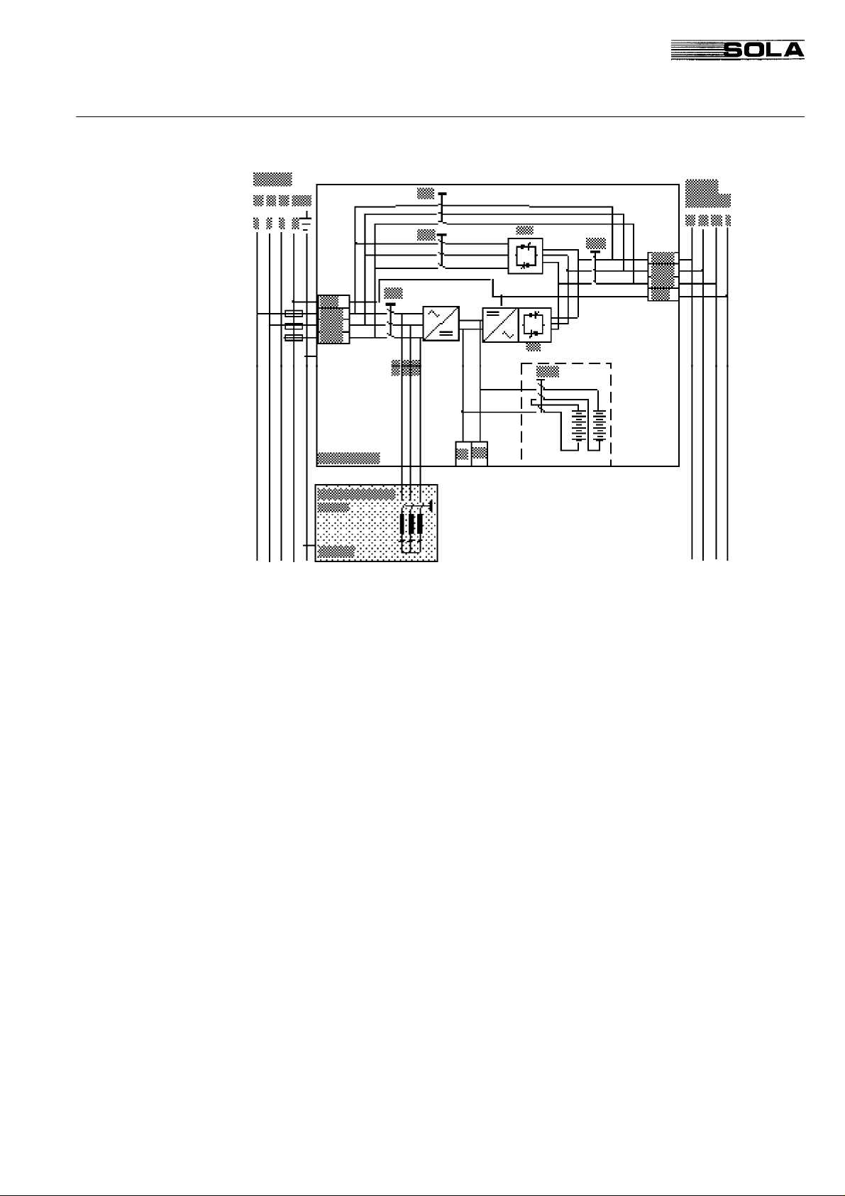
FIG. 1.11.1 Interconnection of parallel units with integrated maintenance bypasses and separate bypass
terminals.
(*) Note: Internal Battery only for 10-30kVA units
Page 40

SOLA 4000 - Installation and Initial Start-Up
1 Installation
FIG. 1.11.2 Interconnection of parallel units with common maintenance bypass and separate bypass
terminals.
(*) Note: The internal maintenance bypass may or may not be installed in this configuration.
(**) Note: This cable must be twisted pair, total shield (refer to section 1.4)
(***) Note: Internal Battery only for 10-30kVA units
Page 41

SOLA 4000 - Installation and Initial Start-Up
1 Installation
1.11.1 Installation of the Interconnection Cables
There are two interconnection cables supplied with the units for
each additional unit to the first unit. These cables must be connected between the units as shown in FIG. 1.11.4 One cable is
connected to either CN12 or CN13 (the other end being connected
to the corresponding connector of another unit), and the other
cable is connected to either of CN10 or CN11, again with the other
end connected to the corresponding connector of another unit. In
this way, all units will be interconnected by two cables in a BUSCommunication system (Daisy-chain connection).
Note: If the unit is to be added to one already installed stand-alone
unit which has not been previously tested in a parallel configuration, the supports and mounting screws to mount the cable to the
p.c.b are supplied with the cables. They must be mounted at both
sides of the selected connectors in order to fix the cables securely
to the connectors with the supplied screws.
FIG. 1.11.3 Location of connectors on the IBYBP-CP pcb.
FIG. 1.11.4 Interconnection of control BUS cables between parallel units
Page 42

SOLA 4000 - Installation and Initial Start-Up
1.12 Battery Installation
Battery Installation must be in accordance with local safety
standards.
General The batteries are charged. The installation should only be made by
appropriately qualified personnel. The screw connections between
the batteries should be tightened with a torque wrench (max. 7
Nm).
1.12.1 Installation of Internal batteries
SOLA 4000 (10-30kVA)
Internal Battery (24Ah) Installation
• Place five battery blocks on the trays of the first level.
• Place nine battery blocks on the trays of the second, third and
fourth level.
• Interconnect the blocks in series (see FIG.1.12.1)
1 Installation
1° LEVEL
2° LEVEL
3° LEVEL
Warning: after assembly there is a voltage of 67,5 V on the first
level, and 121,5 V on the second, third and fourth levels.
4° LEVEL
Page 43

SOLA 4000 - Installation and Initial Start-Up
1 Installation
Internal Electrical Connections
Cable (1) n° 3; L = 280 mm; diameter 16 mm
Cable (2) n° 8; L = 420 mm; diameter 16 mm
Cable (3) n° 4; L = 490 mm; diameter 16 mm
Cable (4) n° 2; L = 650 mm; diameter 16 mm
Support (CA1) n° 4; See Fig. CA1
Support (CA2) n° 9; See Fig. CA2
2
2
2
2
FIG. 1.12.1 Internal Battery connections.
Copper bars for battery connection Two copper plates diam. 0,5 mm. are used.
CA1
CA2
Page 44

SOLA 4000 - Installation and Initial Start-Up
1 Installation
1.12.2 Installation of External Batteries
External Battery (38 Ah) Installation 38 Ah external batteries are installed in a B3/38 battery cabinet. To
assemble the battery cabinet:
• Place four battery blocks on the trays of the first level (see FIG.
1.12.2).
• Place six battery blocks on the trays of the second and third
levels (see FIG. 1.12.3).
• Interconnect the blocks in series (block 1 / negative pole ==>
block 2 / positive pole,....)
Warning: after assembly there is a voltage of 48 V on the first
level, and 72 V on the second and third levels.
• If necessary secure with strapping (against vibrations).
• Insert the trays into the battery cabinet as shown in FIG. 1.12.4
FIG. 1.12.3 B3/38: battery trays in the
second and the third level
FIG. 1.12.4 Battery cabinet B3/38
Page 45

SOLA 4000 - Installation and Initial Start-Up
1 Installation
Important: Open battery switch IB before connecting the cables.
• Place the trays with the
batteries on the corresponding levels in the UPS.
• Connect the battery blocks
of the various levels to the
battery switch IB, and IB to
the terminals, as shown in
FIG. 1.12.5 and FIG. 1.12.6
Ensure appropriate ventilation of the battery room according to the
standard EN50091-1, to prevent the risk of an explosion.
Page 46

SOLA 4000 - Installation and Initial Start-Up
1 Installation
FIG. 1.12.6 B3/38 internal electrical connections
Page 47

SOLA 4000 - Installation and Initial Start-Up
1 Installation
External Battery (65 Ah) Installation 65 Ah external batteries are installed in a B3/65 battery cabinet. To
assemble the battery cabinet:
• Remove the battery switch IB and the terminals.
• Insert the battery blocks from the front and rear sides.
Warning: after assembly there is a voltage of 192 V at the front
and rear side.
• Remount the battery switch IB and the terminals.
Important: Open battery switch IB before connecting the cables.
• Connect the battery blocks on the various levels to the battery
switch IB, and IB to the terminals, as shown in FIG. 1.12.8 and
FIG. 1.12.9
FIG. 1.12.7 Battery cabinet B3/65
FIG. 1.12.8 B3/65: switch IB and terminals
Page 48

SOLA 4000 - Installation and Initial Start-Up
1 Installation
FIG. 1.12.9 B3/65 internal electrical connections
Page 49

SOLA 4000 - Installation and Initial Start-Up
1 Installation
Connection Between UPS and Additional
Battery Cabinets
Important: Open all battery switches IB before connecting the
cables. Observe the indicated wiring polarity.
• For UPS systems with external batteries: connect the external
batteries as shown in FIG. 1.12.10
• After wiring, check that the external battery is connected with
correct polarity.
Connection of Auxiliary Contacts
FIG. 1.12.10 UPS with additional battery cabinet
For the standard battery cabinet, the terminals C1, C2, C3 and C4
are connected to the corresponding terminals in the UPS cabinet
as in FIG. 1.12.10.
If a battery is installed without standard cabinet(s), then a voltagefree auxiliary contact (normally closed) should be provided, along
with a dc shunt trip circuit, for the battery circuit breaker / fuse
switch. The auxiliary contact is connected to the terminals C1 and
C2. The shunt trip circuit is connected in series with C3 and C4 and
the appropriate number of batteries in order to achieve the rated
shunt trip coil voltage.
Page 50

SOLA 4000 - Installation and Initial Start-Up
2 INITIAL START-UP
2.1 Start-Up Procedure
2 Initial Start-Up
General
Preparation
A: Rectifier Power Supply Check • Switch on the external mains supply to the UPS.
With the Start-Up procedure the correct installation of the UPS
according to the previous section is checked. It must be carried out
by specialised personnel.
Safety precautions according to the appropriate local safety standards must be applied.
Should problems arise during the Start-Up Procedure, call for
service assistance.
For carrying out the Start-Up Procedure you need a 3 1/2 digit
voltmeter with 1% accuracy, an AC/DC clip-on ammeter and a
small screwdriver for potentiometers (only when necessary).
The installation of the UPS must have been carried out according
to the previous section.
• Check that the ventilation system of the UPS room is ready to
operate.
• Check that all switches IRP, IRE, IUG, IBY, IB are open and
the load is off.
• Check that the supply voltage at terminals 1-L1, 1-L2, 1-L3 is
within ±10% of the UPS rated voltage.
• Close IRP.
Does the display on the CPHC16 -R pcb for the rectifier give the
?
indication "P"?
yes The phase rotation at the input is incorrect.
• Open IRP, switch off the external mains supply and exchange
any two of the cables at input terminals 1-L1, 1-L2, 1-L3.
• Return to A.
no The rectifier supply voltage is o.k. and the rectifier will automati-
cally start to operate.
• Wait until the Data Monitor Panel / NCP is illuminated
• Press the START push-button on the front of panel (or the push
button PB2 on the top of ICP card) the inverter will start and
after approximately 10s the green led L16 will be permanently
lit.
• Press the push-button PB3 on the bottom of ICP card:
after few seconds the three green leds on SS/FY card will be lit.
One led is flashing:
- green LED 3 flashing: "Battery switch open". Note that when
using the external battery cabinet this function is desabled.
NOTE: If the battery switch indication is not blinking then the connections to C1
and C2 in the battery cabinet are not correct. Refer to the section "Installation".
Page 51

SOLA 4000 - Installation and Initial Start-Up
2 Initial Start-Up
B: Inverter Voltage Adjustment • On the SS/FY pcb, measure the voltage at the screws Inverter
R, Inverter S, Inverter T with respect to the neutral terminal 5N.
Does this voltage correspond to the desired voltage?
?
no • Adjust the voltage to the desired value individually for each
phase using P3, P4 and P5 on the ICT-2 pcb.
NOTE: If the inverter output voltage is changed, the value at
TP1 (adjusted with P1) on the ICP pcb should be checked. (6V
corresponds to nominal voltage). Note also that for parallel
systems, if the voltage is changed here, the current sharing will
also be affected. Therefore, change voltage settings ONLY IF
ABSOLUTELY NECESSARY. Small variations of the voltage will not
affect system performance. The UPS is already pre-calibrated
in the factory with nominal load.
yes • Continue with C
C: Inverter free-run frequency check • Insert a pin d=2mm in the red test point S1 on the ICP pcb. The
red LED LD3 on the ICP pcb must be permanently lit. The
inverter frequency is now free-running without the internal
oscillator.
• On the SS/FY pcb, measure the inverter frequency on the
screws Inverter R, S or T with respect to neutral.
• Check that the frequency is set at the required value (50/60 Hz
+/- 0,1 Hz). It can be adjusted with P1 on the ICT-2 pcb. Remove the pin from S1. The inverter now synchronises with the
internal oscillator.
• Make sure that the batteries have been installed according to
the instructions for installation.
With an external battery cabinet B3/38:
• Measure the battery voltage in the battery cabinet at the battery
switch between cables:
- -290 (-) and -1 (+)
- +1 (-) and +4 (+)
With an external battery cabinet B3/65:
• Measure the battery voltage in the battery cabinet at the battery
switch between cables:
- -290 (-) and -1 (+)
- +1 (-) and +2 (+)
Does this voltage have positive polarity?
?
no • Open IRP, wait for 5-10 minutes, and then reconnect the
battery cables at the terminals which lead to the switch(es)
where the wrong polarity was detected.
• Return to D.
yes • Check the voltage between the battery terminals B+ and B-.
The value of this voltage should be already set according to the
amount of batteries installed.
• Close battery switch IB.
The alarm "battery switch open" stops.
Page 52

SOLA 4000 - Installation and Initial Start-Up
• If your unit has separate supplies for the rectifier and bypass
(terminals 4-L1, 4-L2, 4-L3, 4-N), switch on the external supply
for the bypass. Check that the bypass supply voltage at terminals 4-L1, 4-L2, 4-L3, 4-N is within ±10% of the nominal input
voltage.
If there are no separate input terminals then the bypass input is
the same as that checked previously for the rectifier input.
• Close IUG.
• Close IRE.
Does the display on the CPHC16 -S pcb for the bypass give the
?
indication "P"?
yes • Open IRE and exchange any two of the cables at the bypass
input terminals 4-L1, 4-L2, 4-L3.
• Return to E.
2 Initial Start-Up
no • Are the status LEDs (green) 1, 2, 3, 14, 16, 17, 19, 26, on the
yes:
F: Synchronisation Check
operating panel continuously on?
no: Check that the mains frequency is in tolerance.
OK?
yes: Is the pcb CPHC16 -S for the bypass
correctly functioning? The display should be
rotating clockwise.
no: Call for service assistance.
yes: Check again the input supply. Check
that it is in accordance with the UPS
rating label.
no: The mains frequency must be within
tolerance in order for the bypass to be
availabe
Continue with F.
• Check that the green LED LD1 on the ICT-2 pcb is permanently
lit and there is no "S" indication on the bypass electronics.
• On the SS/FY pcb, measure the voltage between the screws
Bypass R and Inverter R. Then repeat for the other two phases.
Are the voltages < 25Vac?
?
no • If the voltage is continuously fluctuating from 0 to 400V there is
a synchronisation problem. Switch off IRE and call for service
assistance.
If the voltage is slightly higher but relatively constant and the
default values have been re-entered using the serial interface
on the CPHC16 -S p.c.b., then the synchronisation may need to
be re-adjusted. This can be easily confirmed by comparing the
two sinewaves for a possible phase difference.
Are the two waveforms phase-shifted?
yes: The synchronisation must be re-adjusted using the serial
interface of the CPHC16 -S pcb and the PSRS232 and a
portable computer.
Page 53

SOLA 4000 - Installation and Initial Start-Up
2 Initial Start-Up
no: The difference is probably due to distortion of the mains
voltage (the inverter voltage is an almost perfect
sinewave)
Continue with G
yes: Continue with G
G: Static Switch Commutation Check
H: Battery Charging Current Limitation
Check • Connect the load and open IRP.
no The rectifier is not yet in battery current limitation. In order to check
• COMMUTATION TO THE BYPASS
Press the pushbutton on the CPHC16-S pcb for the bypass.
The static switch SSB will switch on and SSI will switch off, as
indicated on the front panel and on the SS/FY pcb (red LEDs).
• COMMUTATION TO INVERTER
Press the pushbutton PB3 at the bottom of the ICP pcb. The
static switch SSI will switch on and SSB will switch off, as
indicated on the front panel and the SS/FY pcb (green LEDs).
The load is now supplied only by the batteries.
• Discharge the batteries for about 2 minutes at nominal UPS
load or longer if the connected load is smaller than nominal
UPS load
• Close IRP again.
• After 30 seconds, measure the battery voltage.
Is the battery voltage lower than the set floating charge voltage?
?
the battery current limitation you must discharge the batteries for a
longer period.
• Return to H.
yes The battery current limitation can now be checked according to the
battery installed. Standard setting is 10% of the battery capacity.
• Measure the battery recharging current with a dc clip-on ammeter.
Is this approximately 10% of the battery Ah capacity?
?
no Check the settings of the dipswitch S1 on the CPHC16 -R pcb for
the rectifier according to JUE400899 programming of PCBs (V2.0
or later). Otherwise, the battery charging current may need to be
adjusted using the RS232 connector on the CPHC16-R pcb and a
portable computer. This must be performed by first discharging the
battery by switching off IRP, connecting the PC and adjusting the
charging current. The battery must remain connected through-
out the procedure.
• Return to H.
yes THE START-UP PROCEDURE HAS BEEN SUCCESSFULLY COMPLETED NOW.
Page 54

SOLA 4000 - Installation and Initial Start-Up
3 Additional Start-Up Proced. for Multi-Unit Systems
3 ADDITIONAL START-UP PROCED. FOR
MULTI-UNIT SYSTEMS
3.1 Start-Up Procedure for Hot -standby Systems
Repeat the procedure of section 2 for the second unit in the system
(with the first unit off).
Ensure that the interconnecting BUS cable is connected according
to section 1.9.1 and FIG 1.9.3.
J • Switch off the inverter at the second unit with PB2 at the top of
the ICP pcb. The unit will transfer to the bypass supply.
• Switch on IRP of the first unit.
• Ensure that the switch IUG of this unit is off.
• Switch on IRE of the first unit.
After approx. 10 seconds the display will flash with a "U" indica-
tion and static bypass switch SSB will be closed.
• Measure across the output switch IUG from input to output of
each phase.
Is this voltage less than 2V a.c for all three phases?
?
no The output power interconnections are incorrect and must be
reconnected correctly. Switch off both units and the mains
supply and recheck the connections.Return to J
yes Continue
• Close IUG of the first unit. The two static bypasses (SSB) are
now connected in parallel.
• Close the battery switch of the first unit.
• Start the unit by pressing "START" on the front operating panel.
when the inverter is synchronised, the unit will transfer the
inverter to the output (SSI closes and both SSB switches switch
off).
• Press "START" on the operating panel of the second unit.
The inverter will start and become ready (check that the green LED
LD6 on the ICP pcb is illuminated) but the static switch SSI will not
close.
• Check the commutation of the inverters by pressing PB2 at the
top of the ICP pcb on the unit currently with SSI closed.
• Restart the inverters (with PB2 on ICP or with "START").
THE SYSTEM IS NOW IN NORMAL OPERATION AND THE HOT-STANDBY START-UP
HAS BEEN SUCCESSFULLY COMPLETED.
Page 55

SOLA 4000 - Installation and Initial Start-Up
3 Additional Start-Up Proced. for Multi-Unit Systems
3.2 Start-Up Procedure for Parallel Systems
Repeat the procedure of section 2 individually for all units in the
system, with the the other units off.
Ensure that the interconnecting BUS cables are connected according to section 1.10.1 and FIG 1.10.3.
• Open IRP, IRE, IB and IUG of the last unit checked with the
procedure in section 2.
K • Ensure that no load is connected to the system output.
• Ensure that all IUG switches are open.
• Switch on the IRE switches of all units. Wait until all units give
a flashing "U" indication on the display of the CPHC16-S pcb.
• Close IUG on one unit only.
• At each unit in turn:
Measure across the output switch IUG from input to output of each
phase.
Is this voltage less than 2V.a.c for all three phases for every unit?
?
no
yes Continue.
The output power interconnections are incorrect and must be
reconnected correctly. Switch off all units and the mains supply
and recheck the connections.
Return to K
• Close the IUG switches on all units. The static bypasses (SSB)
will now be connected in parallel for all units.
• Close IRP of all units.
• When the front operating panel is initialised on all units (after 3
beeps), close the battery switches of the respective units.
•Press the "START" pushbutton on any one unit. The inverter
will start and when synchronised to the bypass supply, transfer
to the system output and all static bypass switches (SSB) will
open.
• Press the "START" pushbutton on each successive unit in the
system, each time checking that the SSI closes on the unit and
that the system operates in parallel operation.
• Commutations to the bypass/inverter supplies may be checked
by pressing the pushbutton on the CPH16 -S pcb and PB3 at
the bottom of the ICP pcb.
• Apply a load to the UPS system and check for correct sharing
of the load currents on each phase. If stand-alone units have
been converted for parallel operation, the current sharing needs
to be checked and is best performed with a load as close as
possible
Page 56

SOLA 4000 - Installation and Initial Start-Up
3 Additional Start-Up Proced. for Multi-Unit Systems
to the nominal load. Measure the currents at the output of each
module on phase T. If this current varies by more than ± 1% for
this module, fine adjustment can be made with P1 on the IPR
pcb.
Check the currents at the output of each module on phase S.
These currents must be balanced to within ± 1% by finely
adjusting the inverter voltage of phase S (P4 on ICT-2). i.e. If
the module is supplying more current than the system average,
the inverter voltage of this module must be reduced slightly.
Repeat for phase R currents by finely adjusting the R phase
inverter voltage of this module with P3 on the ICT-2 pcb until
the currents on the phase R of all modules are equal to within
± 1%.
• THE SYSTEM START-UP HAS NOW BEEN SUCCESSFULLY COMPLETED.
Page 57

Contents of JUE 401266
SOLA 4000 - Operation
Chapters
1 OPERATING MODES 2
1.1 General 2
1.2 Led Indication 3
2 OPERATING MODES STAND-
ALONE UNIT 4
2.1 Normal Operation 4
2.2 Battery Operation 4
2.3 Bypass Operation 5
2.4 Maintenance Bypass Operation 5
2.5 Standby Operation 5
3 OPERATING MODES HOT-
STANDBY OPERATION 6
3.1 Normal Operation 6
3.2 Operation with an Inverter Failure 6
5 OPERATING INSTRUCTIONS 11
5.1 Switching On the UPS System/from
Maintenance Bypass 11
5.2 Switching Off the UPS System/to
Maintenance Bypass 13
5.3 Switching On any one unit within a
System (Parallel and Hot-standby Systems) 14
5.4 Switching Off any one unit within a
System (Parallel and Hot-standby Systems) 15
5.5 Emergency Power Off 16
Figures
FIG. 2.1 Normal Operation 4
FIG. 2.2 Battery Operation 4
3.3 Battery Operation 6
3.4 Bypass Operation 7
3.5 Maintenance Bypass Operation 7
4 OPERATING MODES PARALLEL
AND PARALLEL/REDUNDANT
OPERATION 8
4.1 Normal Operation 8
4.2 Partial Load Operation 8
4.3 Battery Operation 9
4.4 Operation with an Inverter Failure 9
4.5 Bypass Operation 10
4.6 Maintenance Bypass Operation 10
We reserve the right to modify the contents of this document without notice. BEST POWER- BORRI ELETTRONICA INDUSTRIALE S.r.l Via 8 Marzo Soci, Bibbiena (AREZZO)
FIG. 2.3 Bypass Operation 5
FIG. 2.4 Maintenance Bypass Operation 5
FIG. 2.5 Standby Operation 5
FIG. 3.1 Normal Operation 6
FIG. 3.2 Operation with an Inverter failure 6
FIG. 3.3 Battery Operation 6
FIG. 3.4 Bypass Operation 7
FIG. 3.5 Maintenance Bypass Operation 7
FIG. 4.1 Normal Operation 8
FIG. 4.2 Partial Load Operation 8
FIG. 4.3 Battery Operation 9
FIG. 4.4 Operation with an Inverter Failure 9
FIG. 4.5 Bypass Operation 10
FIG. 4.6 Maintenance Bypass Operation 10
ISSUED
A
See Rev. Doc. JSE 401440
See Rev. Doc. JSE 401547B
04.02.97
20.06.97 T. Boon
23.09.97
T. Boon
T. Boon
04.02.97M. Porpora
A4 161
JUE 401266
Page 58

SOLA 4000 - Operation
1 Operating Modes
1 OPERATING MODES
1.1 General
There are four different operating modes of the standard standalone on-line UPS-system (5 for hot-standby and 6 for parallel
systems), ensuring uninterrupted power supply of the load under all
conditions. Transitions between these operating modes are performed without interruption of the power supply to the load.
Security concept
• In "Normal Operation" any failure, internal or external, will
transfer the UPS system either to "battery operation", to "bypass operation" for a stand-alone UPS or to "operation with an
inverter failure" for parallel and hot-standby systems.
• In "Battery Operation" or "Bypass Operation", with a standalone UPS system, an additional failure may interrupt the
power supply to the load, depending on the kind of failure. In
both operating modes the UPS signals a failure condition
(audible and visual alarm) to indicate that any additional failure
bears the risk of interrupting the power supply to the load.
• As additional security, a second UPS unit may be added and
connected in parallel with the original unit, in a hot-standby
configuration. Therefore, in the case of a failure of one inverter,
the second inverter will take over the load. This system requires the occurrence of 3 or 4 simultaneous failures (the
bypass can be also redundant) before the load is interrupted.
Any number of units can be connected together in this way, the
addition of each unit providing the addition of 1 or 2 additional
security factors. The interconnection of the SOLA 4000 in this
way requires a special cable available from your local distributor.
• Parallel Operation is used to provide redundancy in the same
way as for hot-standby units above and / or an increased
capacity to supply the load, the parallel units exactly sharing
the load requirement.
• "Maintenance Bypass Operation" is used to supply the load
directly from mains during maintenance or repair work.
Warning: Even in case of a total blackout, the UPS will continue to
supply power to the load, therefore all necessary precautions
against direct and indirect accidental contact as specified in national and local safety standards must be followed.
JUE 401266
58
Page 59

SOLA 4000 - Operation
1 Operating Modes
LED 1 MAINS PRESENT
LED 2 RECTIFIER
LED 3 BATTERY SWITCH
LED 4 BATTERY DISCHARGING
LED 5 BATTERY CHARGING
LED 14 BYPASS POWER SUPPLY
LED 15 MAINTENANCE BYPASS SWITCH
LED 16 INVERTER
LED 17 LOAD FED by INVERTER
LED 18 LOAD FED by BYPASS
POWER SUPPLY
LED 19 LOAD IS SUPPLIED
LED 27 BATTERY TEST
LED 28 E.P.O.
LED 26 BYPASS AVAILABLE
LED 29 COMMON ALARM
LED 30 BOOST CHARGE
1.2 LED Indication
The block diagram of the UPS, with integrated LEDs, allows a
quick check of the UPS operating status.
JUE 401266
59
Page 60

SOLA 4000 - Operation
2 Operating Modes Stand-alone Unit
2 OPERATING MODES STAND-ALONE
UNIT
2.1 Normal Operation
"Normal Operation" is the standard operating mode of the UPS
• Mains power is present.
• The rectifier converts ac power to dc power which charges the
batteries and feeds the inverter.
• The inverter converts this dc power to ac power used to feed
the connected load.
2.2 Battery Operation
The "Battery Operation" mode is activated by a mains failure or
rectifier failure
• The rectifier supplies no power.
• The battery supplies the required dc power to the inverter.
• The inverter supplies ac power to the load as described above.
• Power will only be supplied to the load for a certain period of
time depending on the battery capacity and the amount of load
applied.
JUE 401266
60
Page 61

SOLA 4000 - Operation
2 Operating Modes Stand-alone Unit
2.3 Bypass Operation
The "Bypass Operation" mode is activated by an inverter failure or
an overload
• The rectifier supplies dc power only to the battery.
• The static inverter switch SSI opens automatically after the
static bypass switch SSB is closed.
• The load is supplied directly from the mains through the static
bypass line.
2.4 Maintenance Bypass Operation
The "Maintenance Bypass Operation" mode is used to supply the
load directly from the mains during maintenance or repair work.
• In this mode, the individual functional components are completely separated from the load.
• Power for the load is supplied directly from the mains through
the switch IBY.
2.5 Standby Operation
If an appropriately programmmed IPR pcb is inserted in the control
electronic of the stand-alone unit, as an option, this mode of
operation is possible.
• If the load is completely switched off, the inverter and the
inverter static switch SSI, switch off and the UPS commutates
to the bypass supply (SSB closes), thus saving power when the
UPS is not needed.
• When the load is again switched on, the inverter automatically
switches on and the inverter static switch SSI will commutate
the load to the protected inverter supply.
JUE 401266
61
Page 62

SOLA 4000 - Operation
3 Operating Modes Hot-Standby Operation
3 OPERATING MODES HOT-STANDBY
OPERATION
3.1 Normal Operation
"Normal Operation" is the standard operating mode of the hotstandby system.
• Mains power is present.
• The rectifiers of all units convert ac power to dc power which
charges the batteries and feeds the inverters.
• The inverters convert this dc power to ac power.
• The inverter of one unit feeds the connected load.
• The inverter of the other unit(s) is working in standby mode,
ready to takeover the load if there is a failure in the unit supplying the load.
• All units in the system are identical and operate completely
independently of each other.
3.2 Operation with an Inverter Failure
"Operation with an Inverter Failure" is the operating mode of the
hot-standby system after a failure has occurred in one unit.
• Mains power is present.
• The static inverter switch of the failed unit opens automatically
and the static inverter switch of an other unit is closed.
• The rectifier of that unit converts ac power to dc power which
charges the battery and feeds the inverter. The inverter then
converts this dc power to ac power used to feed the connected
load.
• The static bypasses within all units remain ready to supply the
load in case of any additional failure(s) or overload.
3.3 Battery Operation
The "Battery Operation" mode is activated by a mains failure or
rectifier failure.
• The rectifiers of all units supply no power.
• The batteries of all units supply the required dc power to the
inverter of each unit.
• The inverter of one unit continues to supply ac power to the
load.
• The inverter(s) of the other unit(s) are operating in standby
mode, ready to takeover the load, without interruption.
JUE 401266
62
Page 63

SOLA 4000 - Operation
3 Operating Modes Hot-Standby Operation
• If an additional failure in the first unit occurs, or when the
battery of that unit is exhausted, the inverter of another unit will
takeover the load, continuing in battery operation until the
mains returns or the second battery is exhausted.
3.4 Bypass Operation
The "Bypass Operation" mode is activated by an overload or by
inverter failures in all units or by a manual commutation.
• The rectifiers supply dc power only to the batteries.
• The static inverter switch SSI of the unit supplying the load
opens automatically after the static bypass switch SSB is
closed.
• The load is supplied directly from the mains through the static
bypass.
• If the transition to "Bypass Operation" was caused by a temporary overload, the UPS system returns automatically to "Normal
Operation", any inverter may takeover the load, when the load
returns to within tolerance.
3.5 Maintenance Bypass Operation
"Maintenance Bypass Operation" is used to supply the load directly
from mains during maintenance or repair work.
• In this mode, the individual functional components of all units
are completely separated from the load.
• Power for the load is supplied directly from the mains through
the switch IBY.
JUE 401266
63
Page 64

SOLA 4000 - Operation
4 Operating Modes Parallel and Parallel/Redundant
Operation
4 OPERATING MODES PARALLEL AND
PARALLEL/REDUNDANT OPERATION
4.1 Normal Operation
"Normal Operation" is the standard operating mode of the UPS if
the system load is at its nominal value or the system is programmed in a way that all units remain on-line. Otherwise see
section 4.2.
• Mains power is present
• The rectifiers convert a.c. power to d.c. power used to charge
the batteries and feed the inverters
• The inverters convert this d.c. power to a.c. power used to feed
the connected load
• All units are sharing the load current uniformly. This is accomplished by means of the optional parallel-operation-electronic
pcb (IPR).
• All units operate completely independently of each other, each
unit supplying its respective share of the load.
4.2 Partial Load Operation
Single inverters that are not needed to supply the load can be
switched off automatically, thus saving energy and increasing
system efficiency.
• The load is supplied by the remaining inverters
• All rectifiers will continue to operate, charging also the batteries
of the units whose inverters have been switched off
• The system can be easily programmed for the minimum
number of units which must supply the load at any time.
• When the load is reduced, the units will individually decide
which one is to switch off automatically.
• The system may be programmed so that there will always be
one redundant unit on-line.
• If the load is again increased, or in the case of an inverter
failure, the unit(s) which have been switched off will automatically switch on again to share the load.
• If the mains supply fails, all inverters will switch on and connect
to the load in parallel operation in order to maximise the battery
autonomy time, (see section 4.3)
JUE 401266
64
Page 65

SOLA 4000 - Operation
4 Operating Modes Parallel and Parallel/Redundant
Operation
4.3 Battery Operation
The "Battery Operation" mode is activated by a mains failure or
rectifier failure
• The rectifiers supply no power
• The batteries supply the required d.c. power to the inverters
• The inverters supply a.c. power to the load as described in 4.1
• Power will only be supplied to the load for a certain period of
time depending on the battery capacity
• If there were stand-by units switched off at the time of the
mains failure, all units will automatically switch ON in order to
extend the battery autonomy time.
4.4 Operation with an Inverter Failure
This operating mode is activated by a failure in one or more inverters.
• As long as the load is not too great for the remaining units, the
parallel system will stay in UPS (inverter) operation mode,
otherwise see 4.5.
• The static inverter-switch(es) (SSI) of the defective unit(s) will
open automatically, separating them from the load-busbar
• The rectifier(s) of the defective unit(s) will supply d.c. power to
the battery (batteries) only if the respective rectifier is not
defective.
JUE 401266
65
Page 66

SOLA 4000 - Operation
4 Operating Modes Parallel and Parallel/Redundant
Operation
4.5 Bypass Operation
The "Bypass Operation" mode is activated by a multiple inverter
failure or overload
• If the load is greater than 110% of the load capacity of all
available inverters, the static bypasses of all individual units
will connect the load with the mains directly
• All inverter output switches (SSI) will open, inverters may
continue to operate
• The rectifiers continue to charge the batteries
• If the load is reduced to 100% or less of the load capacity of all
available inverters, the system switches automatically back to
normal operation
• All bypasses always switch on together.
• If a standby unit was off at the time of the inverter failure/
overload, it will automatically switch ON and all units take-over
the load.The operation then becomes as in paragraph 4.1
(when there was an overload) or as in paragraph 4.4 (when an
inverter failure occurred).
4.6 Maintenance Bypass Operation
The "Maintenance Bypass Operation" mode is used to supply the
load directly from mains during maintenance or repair work.
• During this mode, the individual functional components are
completely separated from the load (e.g. for maintenance work)
• Power for the load will be supplied directly from mains through
internal or external power switch(es) (IBY)
Note: If the 3-position maintenance bypass cabinet MB3/2 is
installed, the UPS system may be totally isolated from all
supply by switching to the 3rd position "UPS ISOLATED".
Again the load will be supplied through the maintenance bypass
switch.
JUE 401266
66
Page 67

SOLA 4000 - Operation
5 Operating Instructions
5 OPERATING INSTRUCTIONS
5.1 Switching On the UPS System / from
Initial UPS Operating Mode:
The UPS is switched off, the load may or may not be supplied by
maintenance bypass, IBY and all other power switches are open.
Operating Steps:
A: • Switch on the external mains supply for the UPS; both the
rectifier input and the bypass input when separate supplies are
provided.
• Open the UPS front door or the part necessary to allow access
to the switches IRP, IRE, IUG and IBY.
Maintenance Bypass
IBY:
IRP: • Close the IRP switch.
IUG: • Close the IUG switch.
IRE:
IB: • Close the battery switch IB.
B:
IBY: • Open the IBY switch inside all units (or within the External
If the b ypass switch IBY, is not already on, close it now (for
parallel systems with internal maintenance bypasses see Note
1 page11) The load is now supplied by the maintenance bypass.
The rectifier starts and the UPS performs a self-test.
The UPS operating panel will beep 3 times and test all the
LEDs. The audible alarm may continue beeping and can be
muted by pressing "RESET" once.
• Close the IRE switch.
Repeat A above, for all units within the system (Hot-standby and
Parallel systems).
• Check that the LEDs for the bypass and the output are illuminated.
Maintenance Bypass cabinet if installed).
RESET: • Press the pushbutton "RESET" on the operating panel of any
unit.
START: • Press the pushbutton "START" on the operating panel of all
units within the system. The inverter(s) will start and will switch
over to take the load when ready (SSI closes).
Note: The pushbuttons "START" and "RESET" must be depressed
for about 1 sec.
JUE 401266
67
Page 68

SOLA 4000 - Operation
5 Operating Instructions
Final UPS Operating Mode:
The UPS is now in normal operating mode, as described in chapter
"2.1. Stand-alone unit", "3.1 Hot standby systems" or "4.1 Parallel
systems". The green LEDs (L1, L2, L5, L3, L16, L17, L26, L19) on
the operating panel(s) must be illuminated (but not flashing).
Should a problem arise during the Switching On, please follow the
instructions in JUE 401066, Initial Start-up.
Note 1: For Parallel Systems.
If the bypass is off, the output is not supplied and the system has
multiple internal maintenance bypasses and the load is connected,
the load may be excessive for one bypass only. In this case, it is
better to switch off the load or proceed further without switching on
IBY (the static bypasses will only switch on together when enough
are ready to take the load.)
JUE 401266
68
Page 69

SOLA 4000 - Operation
5 Operating Instructions
5.2 Switching Off the UPS System / to Main-
Initial UPS Operating Mode:
The UPS is in any operating mode described in the previous
sections "Operating Modes" (except maintenance bypass operation). All power switches except IBY are closed, and the load is fed
either through the inverter or the static bypass.
Operating Steps:
A: • Make sure that the LEDs 14 and 26 "Bypass Power Supply
CPHC16-S: • Press the pushbutton on the CPHC16 -S pcb to commutate to
IBY
• After LED 18 is illuminated, close the IBY switch.
The load is now supplied by the static bypass and the maintenance
bypass in parallel. If more than one IBY switch is present, close all
switches.
tenance Bypass
O.K." and "Bypass available" are illuminated and not flashing.
the bypass supply.
The UPS or all UPS modules (Hot-standby, parallel) switch to
"Bypass Operation" mode. The yellow LED 18 lights up.
B:IUG: • Open the IUG switch.
IB: • Open the battery switch IB.
IRE: • Open the IRE switch.
IRP: • Open the IRP switch.
After opening the IRP switch the display is only powered by the DC
capacitors and will fade out within a few minutes.
C:
• Repeat the steps in B for all units present.
Note: If the optional SOLA external maintenance bypass switch
(MB3/2 - version 2) is installed, it is not necessary to perform
step B if the switch is switched directly to position 3 "UPS
ISOLATED" in step A
JUE 401266
.
69
Page 70

SOLA 4000 - Operation
IRP: • Close the IRP switch. The rectifier starts and the UPS performs
IUG: • Close the IUG switch.
5 Operating Instructions
5.3 Switching On any one unit within a System (Parallel and Hot-standby Systems)
Initial UPS Operating Mode
The UPS module was switched off using the procedure in section
5.4, all of the power switches in this module are in the off position,
the load is supplied by the remaining unit(s) within the system.
• If this UPS module has an input supply separate to the other
units in the system, switch on the external mains supply for this
UPS module; both the rectifier input and bypass input when
separate supplies are provided.
• Open the UPS front door, or the part necessary to allow access
to the switches IRP, IRE, IUG.
• WARNING: ENSURE THAT THE IUG AND IRE SWITCHES ARE OPEN.
a self test. The UPS Operating Panel will beep 3 times and test
all the LEDs. The audible alarm may continue beeping and can
be muted by pressing "RESET" once.
• NOTE: IN ORDER NOT TO AFFECT SYSTEM PERFORMANCE, IT IS IMPOR-
TANT TO CLOSE IUG NOW.
IRE:
IB:
IPR: S1
START: • Press the pushbutton "START" on the Operating Panel. The
RESET: • Press the pushbutton "RESET" on the Operating Panel.If not
• Close the IRE switch.
• Close the battery switch IB.
• If present, ensure that the micro switch S1 at the bottom of the
IPR pcb is in the AUTO position.
inverter will start. The LED 16 will flash red and 10 seconds
later will turn green and be permanently lit.
already on, the green LED 17 will turn on and the LED 29 must
switch off.
The UPS module is now in normal operating mode, connected in
parallel with the remaining units in the system (parallel systems,
section 4.1 or 4.2) or ready to take over the load in the case of an
inverter failure (hot-standby systems, section 3.1)
.
JUE 401266
70
Page 71

SOLA 4000 - Operation
5 Operating Instructions
5.4 Switching Off / any one Unit within a Sys-
Initial UPS Operating Mode:
The UPS is in any operating mode described in the previous
sections "Operating Modes". All power switches except IBY are
closed, and the load is fed either through the inverter or the static
bypass.
tem (Parallel and Hot-standby Systems)
IPR: S1
ICP: PB2
IRE: • Open the IRE switch.
IUG: • Open the IUG switch.
IB: • Open the battery switch IB.
IRP: • Open the IRP switch.
• At the bottom of the IPR pcb (if present), switch the
microswitch S1 to the manual position.
• At the top of the ICP pcb, press the pushbutton PB2.
• NOTE: IN ORDER NOT TO AFFECT SYSTEM PERFORMANCE, IUG MUST BE
OPENED AT THIS MOMENT.
The rectifier voltage will slowly discharge and all the LED(s) on the
front panel will switch off. When all the LED(s) on all the internal
pcbs are off, the UPS module is free from voltage except at the
inputs of IRP, IRE and IBY and at the outputs of IUG and IBY and
at the respective terminals.
If this UPS module has an input supply separate to the other units
in the system, the input supply switch(es) to this module may now
be opened.
Final UPS Operating Mode:
The UPS module is now shut down. The load is supplied by the
remaining module(s) within the system.
Attention! Even when the input supply to the UPS module is
isolated, there will still be voltage present at the output terminals
and the output of the switches IUG and IBY (from the remaining
modules within the UPS system).
JUE 401266
71
Page 72

SOLA 4000 - Operation
5 Operating Instructions
5.5 Emergency Power Off
Operating Steps:
• To activate the Emergency Power Off, press simultaneously
the two pushbuttons in the E.P.O. section of the operating
panel (For hot-standby and parallel systems, the operation
needs to be performed at one unit only).
Attention! This operation will remove all supply to the load.
Emergency Shut Down:
When E.P.O. is activated, all static switches SSI and SSB and the
battery switch(es) IB (when connected with a trip circuit) are
opened, the rectifier(s) and inverter(s) are switched off. The Data
Monitor Panel / NCP will lose supply when the internal DC filter
capacitors discharge.
Attention! Although the load is no longer supplied by the UPS, the
input and output switches are still closed. Voltage is still present in
the UPS unless the input circuit breaker(s) have a shunt trip circuit
connected with the EPO circuit (see JUE 401066 "Installation and
Initial Start-up", section 1.5).
Reset after Activating E.P.O.
RESET:
IB: • After the front panel is illuminated, close IB.
• To restart the UPS press the RESET push-button PL2 located
on the CPU / NCP pcb inside the front door of the UPS. This
releases the EPO circuit and the rectifier will restart.
Note that if the input switch(es) were automatically tripped, it is
sufficient to reclose the switch(es) without the need to press the
reset pushbutton above.
• Press the pushbutton at the front of the CPHC16-R pcb at the
right side of the UPS control electronic.
• Repeat for all units in the system.
• Press the "RESET" button for one second on the operating
panel.
• Press the "START" button for one second on the operating
panel and repeat for all units in the system (if multiple units are
present).
Final UPS Operating Mode:
The UPS is returned to normal operation, and all power switches
except IBY are closed.
JUE 401266
72
Page 73

Contents of JUE 401267
SOLA 4000 - Operating Panel
Chapters
1 FUNCTIONS 2
1.1 Indication of Important Data 2
1.2 Battery Monitoring 2
1.3 UPS Operating Mode Indication 3
1.4 Alarm Signalling 3
1.5 Remote Monitoring 3
1.6 Emergency Power Off 4
2 LED INDICATION 5
3 COMMUNICATION WITH A PC 9
3.1 Connection to PC 9
3.2 SNMP mode 10
3.3 Service Mode 10
Figures
FIG. 2.1 LED Indication 5
FIG. 3.1 RS232 connection cable 9
FIG. 4.3 Layout of the CPU/NCP pcb 16
FIG. 5.1 Setting of DIP1 19
Tables
TAB 4.1 Setting of SW1 - UPS rating 14
TAB 4.2 Setting of SW1 14
TAB 4.3 Setting of SW1 - Nominal Voltage 14
TAB 4.4 Setting of SW2 15
3.4 Alarms 11
3.5 UPS status 13
3.6 Metering 13
4 PANEL SETTINGS 14
4.1 DIP Switch Settings 14
4.2 Location of DIP switches and pushbuttons
on the CPU/NCP pcb 16
5 REMOTE PANEL 17
5.1 General 17
5.2 Installation 17
5.3 Functions 18
5.4 DIP-switch settings 19
We reserve the right to modify the contents of this document without notice. BEST POWER- BORRI ELETTRONICA INDUSTRIALE S.r.l Via 8 Marzo Soci, Bibbiena (AREZZO)
ISSUED
A
See Rev. Doc. JSE 401440 20.06.97
B
See Rev. Doc. JSE 401490
04.02.97
01.09.97
T. Boon
M. Porpora
M. Porpora
T. Boon
04.02.97
A4 191
JUE 401267
Page 74

SOLA 4000 - Operating Panel
Actual Load The actual load of the UPS is indicated as a percentage of its
Battery Charging Status While the battery is being charged (green LED 5 on), the actual
Battery Autonomy While the battery is being discharged (yellow LED 4 on), the actual
1 Functions
1 FUNCTIONS
1.1 Indication of Important Data
nominal load capacity.
charging status of the battery is indicated as a percentage of the
nominal battery capacity.
battery autonomy is indicated as a percentage of the nominal
battery autonomy.
1.2 Battery Monitoring
Low Battery The Low Battery alarm indicates that only 20% of the battery
autonomy is left. The colour of the LEDs for battery autonomy
indication changes from green to red. In addition the alarm buzzer
beeps.
Battery Test
The SOLA 4000 UPS automatically performs a battery test every
30 days.
Whenever the test shows that the battery is damaged or its capacity is reduced, the red LED "BATTERY TEST", located on the
operating panel is illuminated and the buzzer beeps.
This test is of vital importance, since it monitors the battery, warning of possible failures caused by reduced battery autonomy due to
defective batteries.
However this function can be deactivated with DSW2 - 3 on the
CPU/NCP pcb inside the UPS front door. In this case the LED
"BATTERY TEST" is off.
JUE 401267
74
Page 75

SOLA 4000 - Operating Panel
1 Functions
LED Off If a LED is not illuminated at all, the corresponding section is not
1.3 UPS Operating Mode Indication
On the operating panel a block diagram of the UPS is shown. The
operating mode of the UPS is indicated with LEDs integrated into
the block diagram.
active.
LED On, Green
LED Flashing, Green If a LED is flashing (green), the corresponding section is not o.k.,
LED On, Yellow The corresponding section is OK, but it is not the nominal working
LED Flashing, Red If a LED is flashing (red), the corresponding section is not o.k., and
If a LED is continually illuminated (green), the corresponding
section is o.k.
but the power supply to the load is not currently endangered.
condition of UPS.
the power supply to the load is endangered.
1.4 Alarm signalling
By the UPS Alarms are signalled by the UPS using LEDs and an audible alarm:
• Status LEDs signal an alarm by flashing.
• The integrated buzzer signals an alarm by beeping.
• The buzzer can be muted by pressing "Alarm Reset" at the
operating Panel. The LEDs continue flashing when the alarm
condition is still active.
There are two different types of alarm signals:
• The flashing LED is green and the buzzer beeps slowly if the
power supply to the load is not currently endangered (common
alarm flashing - yellow).
• The flashing LED is red and the buzzer beeps fast if the power
supply to the load is endangered (common alarm is flashing
red).
1.5 Remote Monitoring
The operating panel provides an option to communicate with a
computer through RS232 and RS485 interfaces. The RS232 serial
interface communicates with a PC or mainframe computer, with a
SNMP protocol (SEC). With the RS485 interface it is possible to
transmit all necessary data up to a distance of 400m or to connect
a remote monitoring panel.
JUE 401267
75
Page 76

SOLA 4000 - Operating Panel
1 Functions
1.6 Emergency Power Off
In case of emergency it is possible to switch off the complete UPS
system. This is done by simultaneously pressing the "EMERGENCY POWER OFF" (E.P.O.) push-buttons located on the
operating panel. This function provides UPS disconnection from
the load and galvanically isolates the UPS from the battery.
In the case of parallel and hot-standby configurations, activating
EPO on one unit automatically switches OFF the entire system
(when IUG is closed on that unit).
When E.P.O. is activated, dangerous voltages will still be present
within the UPS cabinet unless the input supply circuit breaker(s)
have a shunt trip circuit connected with the EPO circuit (see JUE
401066 section 1.5).
JUE 401267
76
Page 77

SOLA 4000 - Operating Panel
2 LED Indication
2 LED INDICATION
The block diagram of the UPS, with integrated LEDs, allows a
quick check of the UPS operating status.
FIG. 2.1 - LED Indication
JUE 401267
77
Page 78

SOLA 4000 - Operating Panel
2 LED Indication
LED 1
LED 2
LED 3
LED 4
LED 5
MAINS PRESENT
• Green LED is continually illuminated = Mains O.K.(rectifier).
• Green LED flashing slowly + BUZZER beeping slowly (approx.
every 2 sec.) = Mains is not O.K.
RECTIFIER
• LED off = Rectifier is not supplied
• Green LED is continually illuminated = Mains and rectifier O.K.
• Red LED flashing fast + BUZZER beeping fast (every sec.) =
Rectifier failure
BATTERY SWITCH
• Green LED is continually illuminated = Battery switch closed
• Green LED flashing fast + BUZZER beeping fast (every sec.) =
Battery switch open
BATTERY DISCHARGING
• Yellow LED is continually illuminated = Battery feeding inverter
• Otherwise LED is off.
BATTERY CHARGING
• Green LED is continually illuminated = Battery charging
• Otherwise LED is off.
LED 14 BYPASS POWER SUPPLY
• Green LED is continually illuminated = Mains O.K.(Bypass
supply).
• Green LED flashing slowly + BUZZER beeping slowly = Mains
out of order or not present, or IRE open.
LED 15 MAINTENANCE BYPASS SWITCH
• Red LED is continually illuminated = Maintenance bypass
switch closed
Note: For parallel and hot-standby systems, it may be any
maintenance bypass within the system that is closed.
• Otherwise LED is off.
LED 16 INVERTER
• Green LED is continually illuminated = Inverter O.K.
• Red LED flashing fast + BUZZER beeping fast = Inverter
failure
• LED is off = inverter is switched off.
LED 17 LOAD FED BY INVERTER
• Green LED is continually illuminated = Load fed by inverter
• Red LED flashing and can be reset with the "RESET"
pushbutton; buzzer beeping = Retransfer blocked
• Otherwise LED is off.
JUE 401267
78
Page 79

SOLA 4000 - Operating Panel
2 LED Indication
LED 18
LED 19
LED 27
LED 28
LOAD FED BY BYPASS POWER SUPPLY
• Yellow LED is continually illuminated = Load fed by static
bypass
• Otherwise LED is off.
LOAD IS SUPPLIED
• Green LED is continually illuminated = Load fed either by
inverter or by static bypass and IUG is closed
• Otherwise LED is off.
BATTERY TEST
This test is only performed if the batteries are fully charged. Otherwise the test is skipped and performed in the following month.
• LED off = BATTERY TEST function not active
• Green LED is continually illuminated = BATTERY TEST function activated, but UPS is not performing the test
• Green LED flashing slowly = BATTERY TEST running
• Red LED flashing fast + BUZZER beeping fast = BATTERY
TEST failed. Test battery capacity.
E.P.O.
• Red LED is continually illuminated = E.P.O. has been activated
Note: For parallel and hot-standby systems, EPO may be have
been activated at any unit.
LED 26
LEDs
STATIC SWITCH
• Green LED continually illuminated = Bypass available
• Green LED flashing = Bypass not synchronised but the mains
is OK
• LED off = Mains not OK
BATTERY INDICATOR
a) During the charging phase (green LED L5 ON)
• Green LEDs continuously illuminated indicate the actual battery
autonomy as a percentage of the nominal battery autonomy,
depending on the actual load and battery charging status.
b) During the discharging phase (yellow LED 4 ON)
• If, during the discharging phase, the actual battery autonomy
goes below 20% autonomy, the system signals the alarm "Low
Battery ".
- The BUZZER beeps continually.
- The colour of the "battery indicator" LEDs changes from green to
red.
• The actual autonomy is signalled by the flashing of the corresponding LED.
• When the LED corresponding to 0% autonomy starts flashing:
- The buzzer beeps continually and cannot be muted.
- The inverter will cease to operate soon.
JUE 401267
79
Page 80

SOLA 4000 - Operating Panel
2 LED Indication
LOAD PERCENTAGE
The actual load is indicated by LEDs as a percentage of the nominal load.
• All LEDs off => Actual load = 0 - 10%
• Green LED 20% cont. illumin. => Actual load = 10 - 30%
• Green LED 40% cont. illumin. => Actual load = 30 - 50%
• Green LED 60% cont. illumin. => Actual load = 50 - 70%
• Green LED 80% cont. illumin. => Actual load = 70 - 90%
• Green LED 100% cont. illumin. => Actual load = 90 - 100%
• Red LED 125% cont. illumin. => Actual load = 100 - 125%
- The UPS is in an overload condition.
- The buzzer is beeping continually and cannot be muted.
LED 29
COMMON ALARM
• Red LED continually illuminated and BUZZER beeping fast =
any of the following conditions:
- Inverter Failure
- Battery Switch Open
- Low Battery
- Rectifier Failure
- Paralleling Fault
- Inverter not synchronised (with the bypass supply or internal
oscillator)
- Retransfer blocked
- Overtemperature
- Battery Test Failed
- Inverter not Feeding and bypass off (not active for hotstandby)
- Bypass system not available (but bypass of this unit is available when more than one bypass is installed)
• Yellow LED continually illuminated and BUZZER beeping
slowly = any of the following conditions:
- Mains Failure (rectifier)
- Mains Failure (bypass)
- Battery Discharging
- Bypass not available
- Overload
- Load on Bypass (SSB closed)
- Inverter not synchronised (with the bypass supply )
- Auxiliary Alarm
•Otherwise the LED is off
LED 30
BOOST CHARGE
• Green LED on = Boost charge active
• Otherwise LED is off.
JUE 401267
80
Page 81

SOLA 4000 - Operating Panel
3 Communication with a PC
3 COMMUNICATION WITH A PC
3.1 Connection to PC
The UPS is connected to the PC via the RS232 interface. The
respective connector is the female 9-pin sub-D connector on the
CPU/ NCP pcb on the inside of the UPS front door. At the PC a
serial port is used which can either be a male 9-pin sub-D connector or a male 25-pin sub-D connector.
Cable Specification For connecting the PC and UPS use twisted pair, 24 AWG shielded
cable. Connect the shield to ground at the PC and at the UPS.
FIG. 3.1 - RS232 connection Cable
JUE 401267
81
Page 82

SOLA 4000 - Operating Panel
3 Communication with a PC
3.2 SNMP MODE
With DIP7 of SW2 in the ON position, the UPS can be monitored
and controlled from a remote location by a PC through a SNMP
protocol converter. In this mode, software packages such as
SMARTMON
directly applied using a P.C.
The software runs on PCs with the following Operating systems:
MICROSOFT WINDOWS
MICROSOFT WINDOWS FOR WORKGROUPS
MICROSOFT WINDOWS 95
MICROSOFT WINDOWS NT
IBM OS/2
The software allows:
from Systems Enhancement Corporation may be
- UPS monitoring
- Event logging
- Broadcasting
- Paging
- E - Mail (only for Windows 95)
The use of a modem for remote monitoring is also possible.
The UPS can be connected to a LAN and monitored through an
SNMP protocol.
An external Hardware interface is required to perform the protocol
conversion from SEC protocol to SNMP protocol.
3.3 Service Mode
This mode is intended as a test mode and is used during testing /
maintenance of all units. It is activated by setting DIP 7 of SW2 in
the OFF position.
PC Requirements • A program is available for testing / service purposes.
• The communication parameters must be set as follows:
BAUD = 1200
PARITY = OFF
BITs = 8
STOP BITs = 1
JUE 401267
82
Page 83

SOLA 4000 - Operating Panel
3 Communication with a PC
3.4 Alarms
With a connected PC, the following alarms are realised (SNMP and
service modes):
Rectifier Failure The Rectifier mains is in order but a failure is present within the
rectifier.
Inverter Failure The inverter is ON but the inverter voltage or inverter conditions
are not in order.
Battery Switch OFF The battery switch is OFF
Retransfer blocked
Overtemperature The inverter/rectifier components are operating at an excessive
Mains Failure The mains is not present or not within the specified voltage and
Inverter not Feeding The inverter is not feeding the load and the bypass static switch,
Battery Discharging
The inverter has attempted unsuccesfully to take over the load at
least 5 times within 3 minutes.
To reset, press the "RESET" pushbutton a second time after
muting the alarm.
temperature. This can be due to extreme environmental conditions
or a failure within the inverter or rectifier sections.
If the bypass is available the UPS transfers immediately to the
bypass supply (in the case of a hot-standby system, the second
unit takes over the load, in the case of a parallel system the remaining inverters take over the load). If the bypass or another
inverter is not available then the UPS will continue to supply the
load for a further 10 minutes before shutting down.
frequency tolerances.
SSI is OFF.
The mains or rectifier has failed and the batteries are
discharging.This alarm is activated at a battery voltage of approx.
360Vdc.
Low Battery The remaining battery capacity during discharge has been calcu-
lated to be less than 20% of the nominal capacity.
Battery Test Failed The routine battery test has detected a decrease in capacity of the
battery. The battery must be checked.
Paralleling Fault The inverter has failed to regulate correctly in parallel operation
with another inverter (parallel systems only).
Bypass not Available The bypass mains supply is OK but the bypass is not available to
take the load if the inverter fails (the inverter is not synchronised or
is blocked externally).
JUE 401267
83
Page 84

SOLA 4000 - Operating Panel
Overload The UPS is overloaded by more than the nominal output load
Load on Bypass The UPS system load is being supplied by the bypass supply.
Inverter not synchronised The inverter is not synchronised to the bypass supply.
Auxiliary Alarm This alarm consists of a series of system alarms and includes the
3 Communication with a PC
For systems with multiple static bypasses (hot-standby and parallel/redundant), if the bypass of this unit is available, but the bypass
system is not available, the UPS system cannot transfer to the
bypass supply, due to the fact that there may be insufficient bypasses available within the system.
current
following:
• Oscillator failure
A failure has occurred in the oscillator circuit or a loss of
synchronism with another oscillator of another unit within the
system.
• IUG monitoring failure
An error has occurred within the monitoring circuit of the output
switch (disabled for single units).
• Static switch failure (SSI)
A failure has occurred within the monitoring circuit of the
inverter output static switch.
• Static switch failure (SSB)
A failure has occurred within the monitoring circuit of the
bypass static switch.
• Missing or incorrect bypass trip signal (parallel and hotstandby systems)
An indifference has occurred within the bypass trip logic of this
unit and the remainder of the system.
•System not redundant (parallel /redundant systems)
If the inverter of the unit signalling this alarm fails, the system
must transfer to the bypass supply.
• SSI-ON generator failure (parallel/redundant systems)
A failure or loss of synchronism has occurred with the SSI ON
pulse generator on IPR pcb and may occur during start-up of a
unit in a parallel system. To reset press "START" and then
"RESET".
To determine which of the alarm(s) are present refer to the section
"PCB Description" JUE 401069.
JUE 401267
84
Page 85

SOLA 4000 - Operating Panel
3 Communication with a PC
3.5 UPS status
Additionally to the above alarms, the following status conditions are
realised:
Boost Charge The rectifier is re-charging the battery with a boost charge (accord-
ing to DIN 41773).
Output Switch OFF
Service Bypass ON The load is supplied by any of the maintenance bypass(es).
The output switch (IUG) is OFF and the load is not supplied by this
unit.
3.6 Metering
With a connected PC, the following measurements can be realised
(SNMP and service modes):
Vout(R) (UPS output voltage phase R)
Vout(S) (UPS output voltage phase S)
Vout(T) (UPS output voltage phase T)
Vinv (Inverter output voltage - average of the three
phases).
I(R) (UPS output current phase R)
I(S) (UPS output current phase S)
I(T) (UPS output current phase T)
Pout% (UPS output kVA in % of nom. kVA)
Aut% (Battery autonomy in % of nom. autonomy)
JUE 401267
85
Page 86

SOLA 4000 - Operating Panel
4 Panel Settings
4 PANEL SETTINGS
4.1 DIP Switch Settings
With the DIP switches SW1 and SW2 on the CPU/NCP pcb inside
the front door , the operating parameters can be set according to
actual conditions.
Note: The following settings apply only with the software V2.0 or
later.
DIP Switch SW1
Dip 1 Dip 2 Dip 3 Dip 4
OFF OFF OFF OFF 10
ON OFF OFF OFF 15
OFF ON OFF OFF 20
ON ON OFF OFF 30
OFF OFF ON OFF 40
ON OFF ON OFF 60
OFF ON ON OFF 80
ON ON ON OFF 100
OFF OFF OFF ON 120
TAB. 4.1 - Setting of SW1 - UPS rating
DIP Switch SW1
DIP 5 CONFIGURATION
OFF Not Hot-standby
ON Hot-Standby
UPS RATING
(KVA)
DIP Switch SW1
Nominal Voltage
DIP 7 DIP 8 Vnom
OFF OFF 120
DIP 6 BYPASS - LINE
OFF Installed
ON Not installed
TAB. 4.2 - Setting of SW1
JUE 401267
ON OFF 220
OFF ON 230
ON ON 240
TAB. 4.3 - Setting of SW1
Nominal Voltage
86
Page 87

SOLA 4000 - Operating Panel
4 Panel Settings
DIP Switch SW2
Dip 1 AUDIBLE ALARM
OFF
ON
Audible alarm
ENABLED
Audible alarm
DISABLED
Dip 2
OFF
ON
Dip 3 BATTERY TEST
OFF
ON
DIP 4 TIME CONSTANT
OFF
ON
DIP 5
OFF
ON
DIP 6 FREQUENCY
OFF
ON
DIP 7
OFF
ON
DIP 8
AUTONOMY
ALARM
Autonomy alarm
ENABLED
Autonomy alarm
DISABLED
Battery test
DISABLED
Battery test
ENABLED
FAST
NORMAL
60 Hz
50 Hz
REMOTE
ACCESS
Service mode
SNMP mode
Forced Battery
Test
(If DIP3=ON)
ON
Forced batt. test
OFF
Forced batt. test
ON
OFF
TAB 4.4 Setting of SW2
JUE 401267
87
Page 88

SOLA 4000 - Operating Panel
4 Panel Settings
4.2 Location of DIP-switches and
pushbuttons on the CPU/NCP pcb
The CPU/NCP pcb is located inside the front door at the UPS
cubicle.
FIG. 4.3Layout of the CPU/NCP pcb
PL1 Microprocessor RESET
PL2 Emergency Power Off (E.P.O.) RESET
JUE 401267
88
Page 89

SOLA 4000 - Operating Panel
5 Remote Panel
5 REMOTE PANEL
5.1 General
The Remote Panel is used for remote monitoring of SOLA 4000
systems for distances of up to 400m. It is connected by cable via a
RS485 interface. It can be installed in a control room and provides
the same user interface as the local operating panel.
Only the E.P.O. function is not implemented.
5.2 Installation
The Remote Panel is connected to the UPS by a shielded cable
4x0.5mm of max. 400m length with 9-pole sub-D connectors.
9-pole male sub-D connector, fits
in the remote panel
The Remote Panel is mounted in a box (270x160x80mm).
The Remote Panel is supplied by an external power supply 220/
230/240 Vac, 50 Hz (which must be connected to the output of the
UPS).
The connection between the UPS and the Remote Panel is provided by a Keyboard 5-Wire Jack.
For the Remote Panel housing the same colour is used as for the
SOLA 4000 cabinets.
9-pole male sub-D connector,
fits in the UPS local panel
JUE 401267
89
Page 90

SOLA 4000 - Operating Panel
5 Remote Panel
5.3 Functions
General
Automatic alarm phone calls The Remote Panel can be connected to an external modem
The Remote Panel provides the same LED indications as the
SOLA 4000 operating panel. Alarms are indicated by flashing LEDs
and an integrated buzzer. The alarms can be muted directly at the
Remote Panel by pressing the "Alarm Reset" push-button.
The buzzer can be deactivated by setting switch 2 of DIP1 to the
Off position. The inverter can be switched on from the remote
panel but cannot be switched off.
through the RS232 DB9 connector, in order to perform an automatic phone call to one or two programmed phone numbers (corresponding to Computers in host Mode), in case of one of the below
listed alarm conditions:
• RETRANSFER BLOCKED
• BATTERY TEST FAILURE
• INVERTER FAILURE
• LOAD ON BYPASS
• RECTIFIER FAILURE
The automatic call feature is enabled by setting switch 3 of DIP1 to
the ON position.
One computer can receive alarm messages from 8 different Remote Panels. The Remote Panels (and hence the connected UPS)
can be identified by a number from 1 to 8 which is binarily programmed by setting the switches 6,7 and 8 of DIP1.
In case of an alarm at a certain UPS the corresponding Remote
Panel calls the computer and transmits a two line alarm message
(ASCII characters) with the following structure:
UPS x x =1...8 identifies the UPS
Alarm condition One or more of the above listed alarms
Programming of phone numbers In case of an alarm one or two phone numbers may be called
automatically, i.e. the UPS status may be monitored by one computer only or by two different computers. With switch 4 of DIP1 the
number of computers to be called can be set.
To program the phone numbers to be called connect a PC with a
serial interface to the RS232 DB9 connector on the rear side of the
Remote Panel and run a terminal program.
Type
P1XXXXX...X[CR] to program the first phone number (XXXXX...X)
P2YYYYY...Y[CR] to program the second phone number (YYYYY...Y)
Each phone number may contain up to 20 digits.
To read programmed phone numbers from the panel type
N1[CR] The Remote Panel responds with the first number:
N1=XXXXX...X
N2[CR] The Remote Panel responds with the second number:
N2=YYYYY...Y
The programmed numbers are stored in an EEPROM and are thus
protected against power failures and CPU resets.
JUE 401267
90
Page 91

SOLA 4000 - Operating Panel
5 Remote Panel
Communication timing When an alarm condition occurs, the Remote Panel calls the first
programmed number.
If the line is busy and only one number is to be called, the Remote
Panel waits for 5 minutes and, if the alarm condition is still present,
it tries to call the number again. This procedure will be repeated
until the connection has been established or the alarm condition
ends.
If the line is busy and two numbers are to be called, the second
number will be called. If this line is also busy the first number will
be tried again and so on.
After a successful connection the Remote Panel will normally hold
the line for five minutes. Any additional alarm messages that are
activated during that time will be displayed automatically at the
computer display and one minute will be added to the remaining
connection time. The maximum connection time is, however,
limited to ten minutes.
If during the connection all alarms are deactivated, the Remote
Panel sends the following messages:
UPSx followed by:
UPS OK
and the remaining connection time is set to one minute.
5.4 DIP-switch settings
DIP Switch DIP1
switch 1 Not used
ON
OFF
switch 2 Local buzzer
ON active
OFF not active
switch 3 Automatic call
ON active
OFF not active
switch 4 Phone numbers
ON two phone numbers
OFF one phone number
switch 5 Not used
ON -
OFF -
sw. 6 sw. 7 sw. 8
ON ON ON 1
OFF ON ON 2
ON OFF ON 3
OFF OFF ON 4
ON ON OFF 5
OFF ON OFF 6
ON OFF OFF 7
OFF OFF OFF 8
FIG. 5.1 - Setting of DIP1
UPS number for
identification
JUE 401267
91
Page 92

Contents of JUE 401268
SOLA 4000 - PCB Description
Chapters
1 UPS CONTROL LOGIC 2
1.0 UPS Control Logic 2
1.1 Legend of symbols used 2
1.2 Rectifier 3
1.3 Inverter 5
1.4 Bypass 10
Figures
FIG. 1.1 - IF/PS - R front view 3
FIG. 1.2 - CPHC16 - R front view 4
FIG. 1.3 - ICP front view 6
FIG. 1.4 - ICT-2 front view 7
FIG. 1.5 - IPS-500 front view 8
FIG. 1.6 - IPR front view 9
FIG. 1.7 - IF/PS - S front view 11
FIG. 1.8 - CPHC16 - S front view 12
We reserve the right to modify the contents of this document without notice. BEST POWER- BORRI ELETTRONICA INDUSTRIALE S.r.l Via 8 Marzo Soci, Bibbiena (AREZZO)
ISSUED
A
See Rev. Doc. JSE 401440
B
See Rev. Doc. JSE 401547
04.02.97
20.06.97 T. Boon
23.09.97 T. Boon
M.Porpora
T. Boon
04.02.97
A4 121
JUE 401268
Page 93

SOLA 4000 - PCB Description
1 UPS Control Logic
1 UPS CONTROL LOGIC
1.0 UPS Control Logic
The UPS Control logic is situated in the centre of the front part of
the UPS. It consists of one rack with 7-8 PCBs (depending on the
system configuration). On the covers of the rack, the various
potentiometers, test points and LEDs are briefly labelled.
A more detailed explanation is given in this chapter.
1.1 Legend of symbols used
LED (light emitting diode) - GREEN: normal condition
- RED: alarm condition.
- YELLOW: warning
Potentiometer - For adjustment
(only for qualified personnel)
Test Point - Requires a pin 2mm for
measurement.
Test point/switch - Insertion of a 2mm Pin disables
the described function
Pushbutton - Performs a reset or switching
operation
Micro switch - Switch from manual to auto
matic mode
JUE 401268
93
Page 94

SOLA 4000 - PCB Description
1 UPS Control Logic
IF/PS - R Rectifier electronic power supply
1.2 Rectifier
The rectifier control logic consists of two PCBs.
• input voltage sensing
• rectifier electronics power supply
CPHC16 - R
IF/PS - R Front View FIG. 1.1 illustrates the LEDs of the IF/PS - R PCB which are
PSPA
PSPP
Rectifier control and regulation
• rectifier output voltage regulation
• rectifier output current limitation
• soft-start control
• battery charging current limitation
• generation of the thyristor firing pulses
• input voltage monitoring (phase rotation, mains failure)
• control for parallel rectifiers (with a common battery)
• 12-pulse rectifier control
• Second level current limitation for diesel-generators.
• Boost charging according to DIN 41773.
• Thermal compensation.
accessible from the front.
• + 12V analog circuits power supply OK
• + 16V microprocessor power supply unregulated
PSPA1
+ 15
- 15
• + 12V interfaces power supply
• + 15V auxiliary LEM power supply (illuminated only for 12
pulse configuration)
• - 15V auxiliary LEM power supply (illuminated only for 12 pulse
configuration)
JUE 401268
94
Page 95

SOLA 4000 - PCB Description
CPHC16 - R Front View FIG. 1.2 illustrates the display, switches and connectors of the
DIAGNOSTICS
RESET MAX. Vdc
RS 232
1 UPS Control Logic
CPHC16 - R PCB which are accessible from the front.
- 7 segment display for diagnostics (see table below)
- Reset max. Vdc pushbutton: press when the character "4" is
displayed or the central segment is blinking.
- Reset Boost Charge Alarm
- Reset after EPO (V2.1)
- RS232 connector (male)
RS 485
- RS485 connector (female)
Priority Indication Diagnostics
1 8 E²PROM failure
2 2 Fuse blown
3 C Mains not OK
4 P Wrong phase rotation
5 3 Overtemperature
6 4 Overvoltage
7 Ø Pulse release missing
8 9 Rectifier failure
9 6 Fan failure
10 L Overload
-- Boost charge
(when blinking)
Has left the boost
charge due to a given
"--"
time limit but the
battery was not
completely charged.
Reset with "RESET
max. Vdc" above.
JUE 401268
95
Page 96

SOLA 4000 - PCB Description
1 UPS Control Logic
ICP Inverter control
In normal condition the display shows a red segment rotating clockwise. During the starting phase,
a blinking central segment "-" is displayed. During
parameter acquisition through the serial interface,
the character "A" is displayed. If more than one
alarm is present, only the one with the higher
priority is displayed.
1.3 Inverter
The inverter control logic consists of three PCBs (four for parallel
systems).
• control for the inverter static switch (SSI)
• temperature monitoring
• inverter monitoring and protection
• hot-standby control
• quartz oscillator
• fan monitoring
• inverter electronic power supply monitor
ICT-2 Inverter regulation
• inverter output voltage regulation
• inverter output current limitation
• short-circuit protection
• inverter soft start control
• inverter-bypass synchronisation
• inverter-oscillator synchronisation
• synchronisation monitor:
IPS - 500 Inverter electronic power supply
• inverter electronic power supply
• inverter input voltage monitoring
• generation of the battery-discharging alarm
JUE 401268
96
Page 97

SOLA 4000 - PCB Description
PB2 Inv. ON / OFF
LD1 PSP OK
ICP Front View FIG. 1.3 illustrates the LEDs and switches of the ICP PCB which
LD3 Osc. Failure
1 UPS Control Logic
Inverter control and regulation (parallel configuration)
• parallel regulation of up to 8 inverters
• system control for up to 8 inverters (together with ICP pcb)
• cold-standby control
• load monitoring
• redundancy monitoring
are accessible from the front.
PB1 Reset
LD9 Inverter OK
LD8 Inverter volts OK
LD2 Retr. blocked
LD4 Overtemperature
LD5 SSI failure
LD6 Inverter ready
LD7 IUG failure
S1 Osc. Block.
S2 Inverter Monit. Block.
TP1 INV. Volts
Vnom=6V
P1 INV. Volts
tol.adjust
PB3 SSI ON
- Push to switch the inverter ON/OFF
- Inv. electronic power supply in order: green LED is illuminated
- Defect in the internal quartz oscillator: red LED is illuminated
- RESET
- Inverter in order: green LED is illuminated
- Inv. voltage within tolerance (within +/- 10% of Vnom): green
LED is illuminated
- Retransfer to inv. operation is blocked after 5 attempts within 3
minutes: red LED is illuminated
- Overtemperature within the inv. section: red LED is illuminated
- The inverter static switch has failed to switch ON/OFF: red LED
is illuminated
- All conditions are in order for a retransfer of the load to the inv.
(for hot-standby units, the inv. is ready in case of a failure to
the on-line inv.): green LED is illuminated
- A failure within the monitoring of the output switch: red LED is
illuminated
- Disable the quartz oscillator
- Disable inverter voltage monitoring
JUE 401268
97
Page 98

SOLA 4000 - PCB Description
1 UPS Control Logic
P1 Freq.
Offset
P5 ΦT Volts
ICT-2 Front View FIG. 1.4 illustrates the potentiometers, LEDs and test points of
P4 ΦS Volts
P3 ΦR Volts
P2 Manual Test
LD5 Overload Φ
LD4 Overload Φ S
T
- Proportional to the inv. voltage. 6V ≡ nominal inverter voltage
- Inv. voltage tolerance adjust for 6V at TP1 with nom. voltage
- Push to switch ON the inverter output static switch (SSI)
the ICT-2 PCB which are accessible from the front.
- Frequency offset adjustment (when synchronisation is blocked
at TP5)
- Inverter voltage adjustment phase T
- Inverter voltage adjustment phase S
LD3 Overload Φ R
LD2 Pulse Release
LD1 Synch. OK
TP5
TP4 I
TP3 I
TP2 I
TP1 I
= 4V ΦT
nom
= 4V ΦS
nom
= 4V ΦR
nom
P8 I
P7 I
P6 I
nom
nom
nom
nom
= 6V
ΦT
ΦS
ΦR
- Inverter voltage adjustment phase R
- Inverter voltage adjustment during test operation (jumpers JP1,
JP2, JP3 in position 2,3)
- Overload on phase T: red LED is illuminated
- Overload on phase S: red LED is illuminated
- Overload on phase R: red LED is illuminated
- Pulse release: green LED is illuminated
- Synchronisation OK: green LED is illuminated
- Synchronisation block
- Test point: test voltage = 6Vdc at full load
- Test point: test voltage = 4Vdc at full load on phase T
- Test point: test voltage = 4Vdc at full load on phase S
JUE 401268
98
Page 99

SOLA 4000 - PCB Description
1 UPS Control Logic
IPS-500 Front View FIG. 1.5 illustrates the potentiometers, LEDs and test points of the
IPS-500 which are accessible from the front.
- Test point: test voltage = 4Vdc at full load on phase R
LAS Power - ON
DF1 Power Supply OK
TP15 PSP +12V
TP3 0 V
TP17 PSP-1 + 26V
TP18 PSP-A + 24V
Test
LUV PSP OK
LVI DC Volts OK
- Current limitation adjustment phase T. Adjust for 4Vdc at TP3
- Current limitation adjustment phase S. Adjust for 4Vdc at TP2
- Current limitation adjustment phase R. Adjust for 4Vdc at TP1
- Power ON:green LED is illuminated
- Power supply OK: green LED is illuminated
- Electronics supply voltage +12V
- Electronics ground
- Electronics supply voltage +26V
- Electronics supply voltage +24V
RV4 DC Over
Voltage
RV3 DC Under
Voltage
- Jumper for test operation (suppression of inverter input voltage
monitoring signal)
- Power supply OK: green LED is illuminated
- Inv. input voltage in tolerance: green LED is illuminated otherwise blinking
- Adjustment of overvoltage monitoring threshold for the inverter
input voltage.
- Adjustment of undervoltage monitoring threshold for the inverter input voltage.
JUE 401268
99
Page 100

SOLA 4000 - PCB Description
1 UPS Control Logic
IPR front view FIG. 1.6 illustrates the LEDs, potentiometers, switches and test
sleeves of the IPR pcb that are accessible from the front.
LD1 Parall.Operat
LD2 Red not ok
LD3 Parallel Fault
LD4 Pulse gen. Fail
TP1 I
= 6V
ref
TP2 I
=6V
out
TP3 I
error
TP4 I
TP8 P
TP5 I
TP7 P
= 8V
load
= 8V
syst
TP6 I
out
= 6V
syst
=6V
rms
rms
- Parallel Operation On: This inverter is connected with another
or more inverters to the output in parallel.
- Redundancy Not OK: Redundant units only.The load has increased or an inverter is off so that if this unit fails, the system
must transfer to the bypass supply.
- Parallel Fault: A fault has occurred with the regulation of the
inverter in parallel with another inverter.
- SSI pulse generator failure: A failure or loss of synchronism has
occurred within the SSI ON pulse generator. To reset press PB3
and then PB1 on the ICP pcb.
- Reference current for parallel regulation 6Vrms = nominal current of the system (0.8 p.f.).
- Inverter output current for parallel regulation 6Vrms = nominal
current of this unit (0.8 p.f.).
- Difference current for parallel regulation
- Output current of this unit. 8Vdc = nominal load current of this
unit (0,8 p.f.)
- System output current. 8Vdc = nominal load current on the system (0.8 p.f.)
red
- Redundancy current. 8Vdc = nominal load current on the remainder of the system (without this unit, 0.8 p.f.)
- Power of this unit. 6Vdc = nominal load power on this unit
- Power of the system. 6Vdc = nominal load power on the system
TP9
TP10
P1 I
P2 I
P3 I
P4 I
P5 P
P6 P
out
load
syst
syst
S1
ref
out
Manual
Auto
- Output voltage phase T
- Output voltage phase R-S
- Adjust for 6Vrms at TP1 with nominal load current (0.8 p.f.)
- Adjust for 6Vrms at TP2 with nominal load current (0.8 p.f.)
- Adjust for 8Vdc at TP4 with nominal load current (0.8 p.f.)
- Adjust for 8Vdc at TP5 with nominal load current (0.8 p.f.)
- Adjust for 6Vdc at TP7 with nominal load
- Adjust for 6Vdc at TP8 with nominal load
- Manual: manual switching on/off of the inverter permitted
- Auto: inverter will automatically switch on/off depending on the
load applied and the internal programming of IPR pcb.
JUE 401268
100
 Loading...