

Page 1

02/20/2001
powerware®9
Prestige Series
User’s Guide
600 VA - 1800 VA
www.powerware.com
Page 2

FCC Statement
The Powerware99 Prestige Series UPSconfigurations vary. Some configurations may or may not be classified by the
Federal Communications Commission (FCC). If your Prestige unit is classified by these standards, the corresponding
information applies:
Class A
NOTE This equipmenthas been tested and found to complywiththe limitsfor a Class A digital device, pursuant to
Part 15 of the FCC Rules. These limits are designed to provide reasonable protection against harmful interference when
the equipment is operated in a commercial environment. This equipment generates, uses, and can radiate radio frequency
energyand, if not installed and used in accordancewiththe instruction manual, may cause interference toradio
communications. Operation of this equipment in a residential area is likelyto cause interference in which case the user
will be required to correctthe interference at his own expense.
Class B
NOTE This equipmenthas been tested and found to complywiththe limitsfor a Class B digital device, pursuant to
Part 15 of the FCC Rules. These limits are designed to provide reasonable protection against harmful interference when
the equipmentis operated in a residential installation. This equipmentgenerates, uses, and can radiateradio frequency
energyand, if not installed and used in accordancewithinstructions, may causeharmfulinterference to radio
communications. However, thereis no guarantee that interference willnotoccur in a particular installation. If this
equipmentdoes cause harmful interference to radio or television reception, whichcan be determined by turning the
equipmentoff and on, the useris encouraged to try to correct the interferenceby one or more of the following measures:
:
Reorientor relocate thereceiving antenna.
:
Increasetheseparationbetweentheequipment and receiver.
:
Connectthe equipmentinto an outleton a circuit different from that to which the receiver is connected.
:
Consultthedealer or an experienced radio/TV technicianfor help.
European EMC Statement
Some configurations are classified under EN50091-2 as “Class-A UPS for Unrestricted Sales Distribution.” For these
configurations, the following applies:
WARNING This is a Class A-UPS Product.In a domestic environment, this product may cause radiointerference, in
which case, the user may be requiredto take additional measures.
EC Declaration of Conformity
Units that are labeled with a CE mark comply with the following EU directives:
73/23/EEC Council Directive on equipment designed for use within certain voltage limits.
93/68/EEC Amending Directive 73/23/EEC.
89/336/EEC Council Directive relating to electromagnetic compatibility.
The EC Declaration of Conformity is available upon requestfor products with a CE mark. For copies of the EC
Declaration of Conformity,contact:
Powerware Corporation
Koskelontie 13
FIN-02920 Espoo
Finland
Phone: +358-9-452661
Fax: +358-9-452-66395
Powerware, PowerPass, Powercare, OnliNet, and OnliSafeareregistered trademarks of Powerware Corporation.
IBM and AS/400 are registered trademarksof International Business Machines Corp.
Novell is a registered trademark of Novell, Inc.
3Com is a registered trademark of 3Com Corporation.
.
Copyright 1993-99 Powerware Corporation, Raleigh, North Carolina, U.S.A. All rights reserved. No part of this
documentmay be reproduced in any way without theexpresswritten approvalof Powerware Corporation.
Page 3
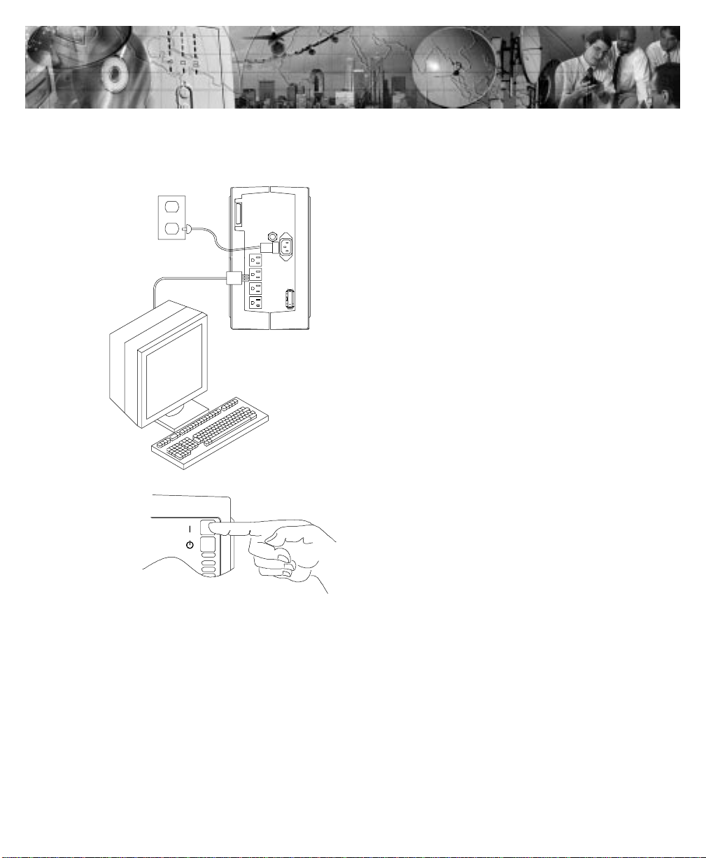
120V MODEL QUICK INSTALLATION
1
2
Page 4
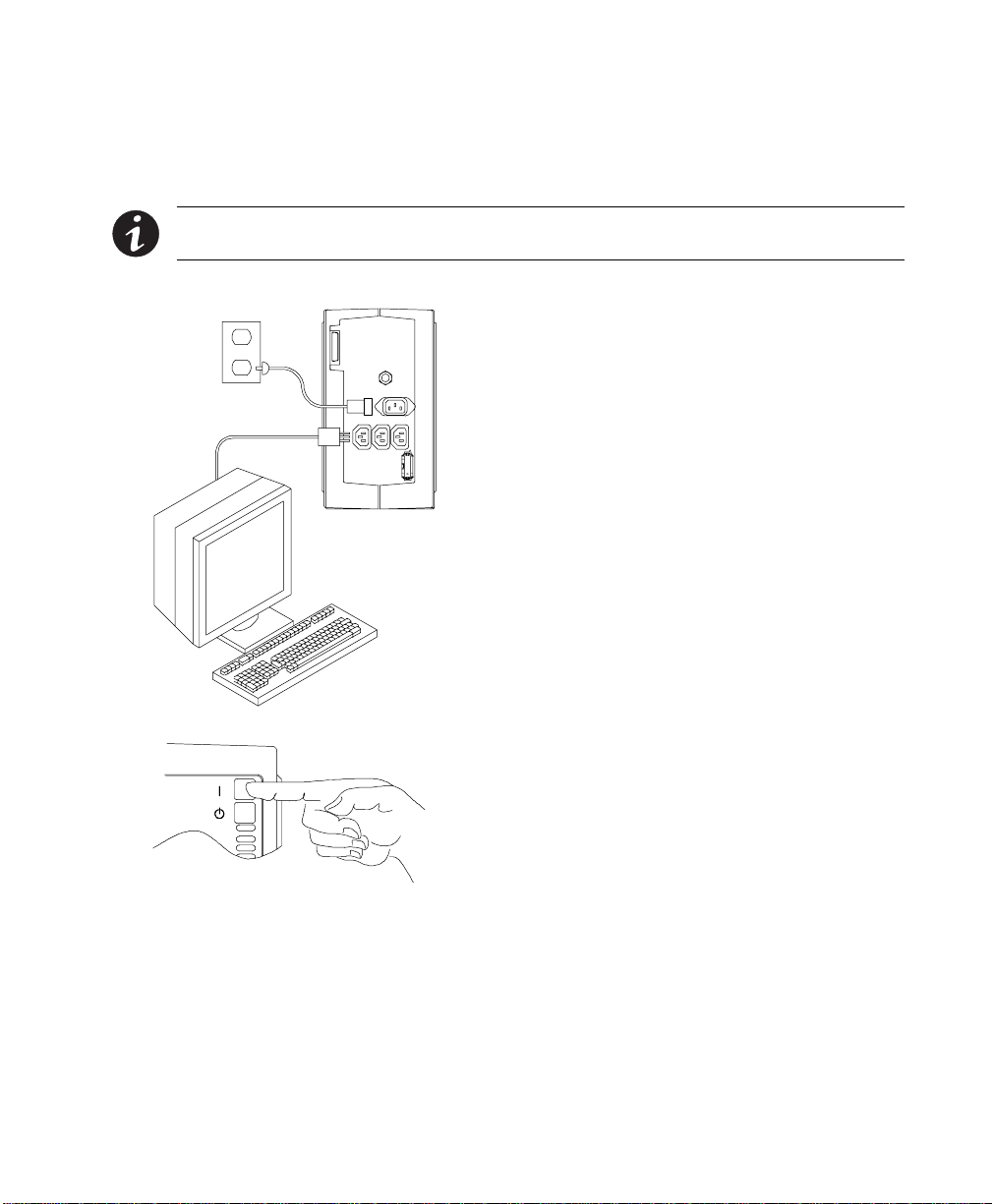
230V MODEL QUICK INSTALLATION
NOTE For208, 220,or 240V models,followtheinstructionsfor changing theoutput voltage on
page 32.
1
2
Page 5

TABLE OF CONTENTS
1 Introduction 1....................................................
UPSModel and BatteryConfigurations 2..............................................
LoadRequirements 2.........................................................
BatteryTimes 3.............................................................
SpecialSymbols 7..............................................................
2 Safety Warnings 9.................................................
Sikkerhedsanvisninger 10.........................................................
Belangrijke Veiligheidsinstructies 12..................................................
Tarkeita Turvaohjeita 13..........................................................
Consignesdesécurité 15..........................................................
Sicherheitswarnungen 16.........................................................
РспейдпрпйЮуейт БуцЬлейбт
Avvisidi sicurezza 20.............................................................
Viktig Sikkerhetsinformasion 21.....................................................
Regulamentosde Segurança 23.....................................................
Предупреждения по мерам безопасности 24...................................
AdvertenciasdeSeguridad 26......................................................
Säkerhetsföreskrifter 27..........................................................
3 Installation 29.....................................................
UnpackingandInspection 29.......................................................
UPSand BatteryCabinetStorage 29...............................................
UPSand BatteryCabinetInstallation 29...............................................
UPSStartup for 120V Models 31..................................................
UPSStartup for 208V-240VModels 32..............................................
Troubleshooting Tips 34...........................................................
18................................................
4 UPS Operation 35..................................................
UPSFront Panel 35..............................................................
OperatingModes 36.............................................................
NormalMode 36.............................................................
BypassMode 37.............................................................
BatteryMode 37.............................................................
Powerware®9PrestigeSeriesUser’sGuide(600 VA-1800VA):www.powerware.com
i
Page 6

Table ofContents
Diagnostics 38.................................................................
BatteryTestonDemand 38......................................................
BatteryStart 39................................................................
UPSShutdown 39...............................................................
Changingthe OutputVoltage 39.....................................................
Usingthe PowerPass 40..........................................................
UsingMaintenanceBypass 41....................................................
5 Communication 45.................................................
InitialCommunications Settings 45...................................................
FrontPanel CommunicationsAccess 46...............................................
UPSSerialCommunicationsMenu 48.................................................
PowerManagement Software 51....................................................
UPSCommunicationsInterfacePort 52................................................
Communications ModeReference Chart 53.............................................
6 Specifications 55..................................................
PrestigeUPSModel Specifications 55................................................
PrestigeUPSPhysicalSpecifications 56...............................................
PrestigeUPSTechnical Specifications 56..............................................
7 Troubleshooting 57.................................................
Resettingthe UPS 59............................................................
Silencing the Alarm 59...........................................................
ServiceandSupport 60...........................................................
Index 61.........................................................
ii
Powerware®9PrestigeSeriesUser’sGuide(600 VA-1800VA):www.powerware.com
Page 7
CHAPTER 1
INTRODUCTION
Congratulations on the purchase of your Powerware99 Prestige Series
uninterruptible power system (UPS). The Prestige UPS meets the
toughest measuresof superior design and manufacturing, including
ISO 9001. You now ownthe most reliable power protectionavailable.
The Prestige provides a steady, well-regulated power supplyfor your
computing andcommunications equipment,whileprotecting it from the
frequent irregularitiesthat areinherent in commercially available power.
Voltage spikes,power surges, brownouts, andpower failures have the
potentialto corruptcritical data, destroyunsaved work sessions, and in
some instances, damageexpensive hardware.
With the Prestige, youcan safelyeliminate the effects ofelectrical line
disturbances and guard the integrity of your systems and equipment.
The optional PowerPass
power to your equipment even whenthe UPSelectronicsare removed
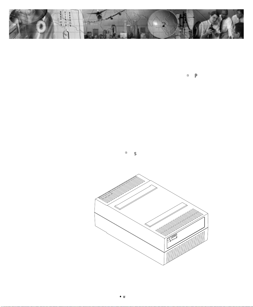
for maintenance or upgrades.Figure 1 shows thePrestige UPS.
9
has a Maintenance Bypass feature that supplies
Figure1.PrestigeUPS
Powerware®9PrestigeSeriesUser’sGuide(600 VA-1800VA):www.powerware.com
1
Page 8

Introduction
UPS Model and Battery Configurations
ThisUPS is designed to work with single-phase, three-wire, AC power
sources. There are two important considerations whenselectingthe UPS
model and battery configuration to properly safeguard your equipment:
:
Load requirements
:
Battery times
Load Requirements
The loadis the equipment to be protected by the UPS.Select theUPS
model that meets the powe r consumption requirements of the load in
volt-amperes (VA). Thetotal load VA should not exceed the UPS VA
rating. To determinethe total load requirements:
1. Obtainthe load ratings fromeither thenameplate or operator’s
manual of the equipment to be protected by the UPS. The
ratings are listed in either watts (W),amperes or amperes
max (A), or volt-amperes.
2. If the ratingis in watts, multiply by 1.4 to obtain the VA
requirement (this isthe typicalrelationship between watts and
volt-ampere ratings in most computing equipment). However,
in some new computingequipment, the power supply is
power-factor corrected and the wattsrating equals the VA
requirement.Check withthe manufacturer to determine
applicability.
If therating isin amperesor amperesmax, multiply by the
inputvoltage to obtain the VA requirement.
2
Powerware®9PrestigeSeriesUser’sGuide(600 VA-1800VA):www.powerware.com
Page 9

Introduction
3. Add all of the resultant VA ratings together to obtain the total
load requirementsof the equipment to be protected (see
Figure 2). If the load consists of thepower-factorcorrected
supplies, it is recommended to use total watts for the load
requirements.
COMPUTER MONITOR EXTERNAL
100WATTS 2AMPS 50VA
100 WATTS x 1.4 = 140 VA
140 VA + 240 V A+ 50 VA = 430 VA (TotalLoad Requirements)
2AMPERESx120=240VA
or 1 AMPERE x 240 = 240 VA
MODEM
50 VA
Figure 2. Volt-Amperes Calculation Example
If thetotal load requirementsof the equipment exceeds the capacity of
the UPS, you musteither reduce the number of pieces of equipment, or
use a UPS witha larger load capacity.
Whendeciding on which pieces of equipment to remove from theUPS,
select equipment thathas a lowerpriorityfor power protection.
Computers, monitors, and modems typically have a higher priority
becausethey couldbe processing or transmitting data when a power
outage occurs.
Battery Times
During a power failure, the UPS battery supplies power to your
equipment, providing time to complete computing activities prior to
UPS shutdown. Theduration of thistime period isdirectly related to the
UPSbattery configuration.By addingbattery cabinets(EXT models
only),you can customize the UPS to provide enough battery time for
normalprocessing activities.
The rating label onthe UPS rear panelshows themodel number. Model
numbers with a “P2” are EXT units; numbers with “HV” are high
voltage units(208 - 240V models). The following tables show the
averagebattery timesby productmodel.
Powerware®9PrestigeSeriesUser’sGuide(600 VA-1800VA):www.powerware.com
3
Page 10
Introduction
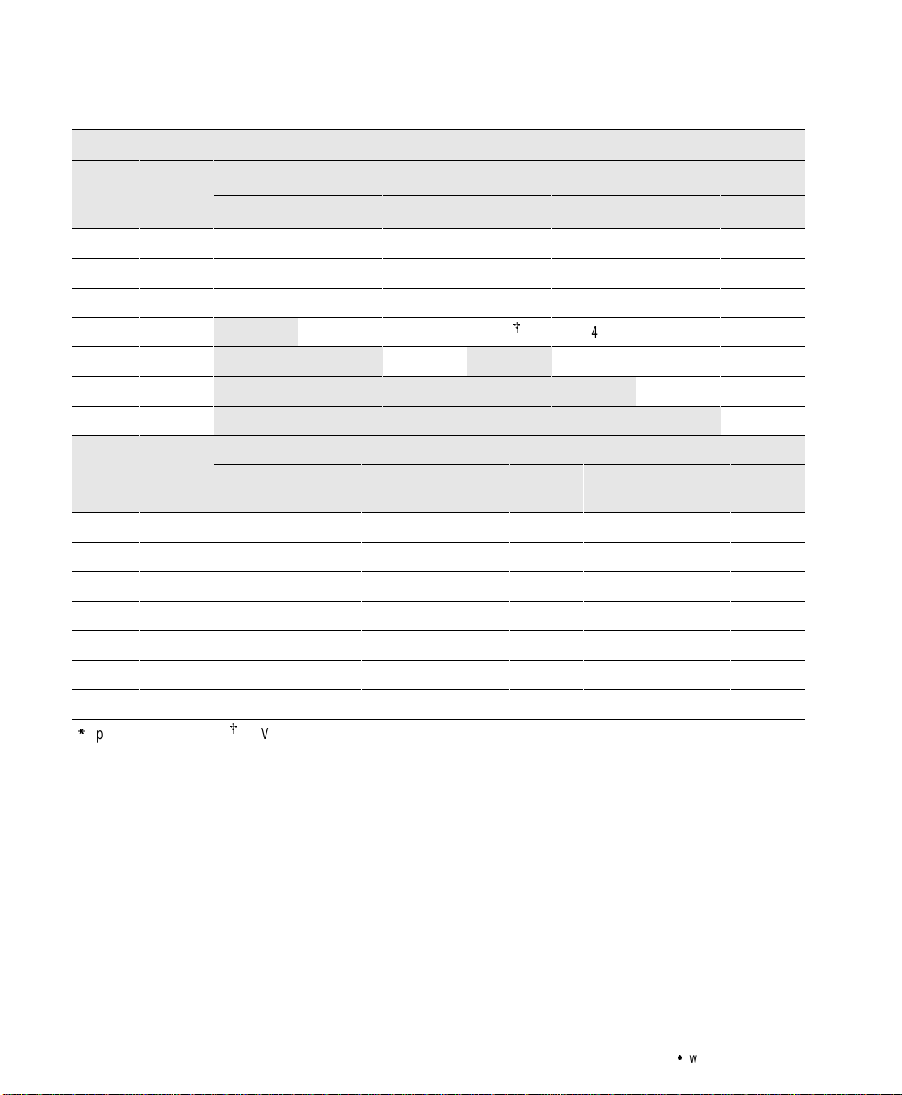
Loa
d
Loa
d
Prestige600 - 1500VA,120V Models
Load
(VA) at
.7PF*
Load
(W)
650 800 1000 750 EXT 1000 EXT 1250 EXT 1500 EXT
InternalUPS Batteries (Rounded to the NearestMinute)
200 140 37 37 37 68 68 68 68
400 280 22 22 22 32 32 32 32
600 420 12 12 12 20 20 20 20
800 560 8 8 15
A
14 14 14
1000 700 6 11 11 11
1250 875 8 8
1500 1050 6
Load
(VA) at
.7PF*
Load
(W)
1/2
Cabinet1Cabinet
ExternalBatteryCabinetConfigurations forEXT Models
11/2
Cabinets2Cabinets
21/2
Cabinets3Cabinets
Cabinets4Cabinets
31/2
200 140 143 216 290 364 438 513 589 663
400 280 69 115 158 198 239 280 320 362
600 420 43 73 105 137 165 194 221 249
750 525 33 56 80 106 134 156 178 202
1000 700 23 39 57 75 95 114 135 151
1250 875 17 30 42 56 70 86 102 118
1500 1050 14 23 32 43 55 67 78 91
*
T ypicalPowerFactor (PF);A750 VA, 525W
4
Powerware®9PrestigeSeriesUser’sGuide(600 VA-1800VA):www.powerware.com
Page 11

Prestige600 - 1250 VA, 208 - 240V Models
(VA)
Introduction
Load
(VA)
at
.7PF*
Load
(W)
600 800 1000
InternalUPS Batteries (Rounded to the NearestMinute)
800
EXT
1000
EXT
1250
200 140 33 33 33 56 56 56
400 280 21 21 21 29 29 29
600 420 11 11 11 19 19 19
800 560 7 7 13 13 13
1000 700 6 10 10
1250 875 8
Load
at
.7PF*
Load
(W)
1/2
Cabinet1Cabinet
ExternalBatteryCabinetConfigurations forEXT Models
11/2
Cabinets2Cabinets
21/2
Cabinets3Cabinets
Cabinets4Cabinets
31/2
200 140 133 203 274 346 418 491 564 637
400 280 70 117 159 201 243 285 328 371
600 420 46 76 110 141 171 200 230 260
800 560 33 55 79 105 132 153 176 199
1000 700 25 42 61 81 102 124 147 161
1250 875 19 32 46 61 77 94 111 129
*
T ypicalPowerFactor (PF)
EXT
Powerware®9PrestigeSeriesUser’sGuide(600 VA-1800VA):www.powerware.com
5
Page 12

Introduction
Loa
d
Prestige1500 - 1800VA,208 - 240V Models
Load
(VA)
at
.7PF*
Load
(W)
UPS withExternalBatteryCabinetConfigurations (Rounded to the NearestMinute)
Internal
UPS
1/2
Cabinet1Cabinet
11/2
Cabinets2Cabinets
21/2
Cabinets3Cabinets
Battery
31/2
Cabinets4Cabinets
200 140 59 128 194 260 327 393 460 527 595
400 280 29 64 107 149 186 224 263 302 339
600 420 19 42 71 102 135 161 189 217 244
800 560 14 32 52 76 100 125 148 169 191
1000 700 11 24 41 59 77 98 119 138 156
1250 900 8 19 32 45 59 76 92 108 125
1500 1050 7 14 25 36 48 60 73 86 101
1800 1200 5 12 20 29 38 48 59 69 80
*
T ypicalPowerFactor (PF)
6
Powerware®9PrestigeSeriesUser’sGuide(600 VA-1800VA):www.powerware.com
Page 13
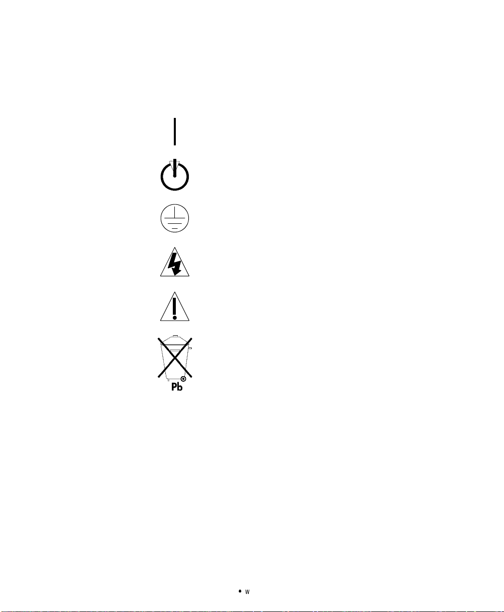
Special Symbols
Introduction
The followingcommon symbols may be found on the UPS:
LOAD ON - Press the button with this symbol to energize the
outputreceptacles (Output On).
LOAD OFF - Press the button with this symbol to de-energize
the output receptacles(OutputOff).
SAFETY EARTHING TERMINAL - Indicates the primary safety
ground.
RISK OF ELECTRICSHOCK - Indicates that a risk of electric
shock is present and the associated warning should be
observed.
CAUTION: REFER TO OPERATOR’S MANUAL - Refer to your
operator’s manual for additional information.
This symbol indicates thatthe UPS batteriesshould notbe
discarded in the trash. The UPS containssealed lead
batteries and must be disposed of properly. For battery
replacementor removal, call your
Help Desk at one of the telephone numberson page 60.
Powerware®9PrestigeSeriesUser’sGuide(600 VA-1800VA):www.powerware.com
Local Distributor or the
7
Page 14

Introduction
8
Powerware®9PrestigeSeriesUser’sGuide(600 VA-1800VA):www.powerware.com
Page 15

CHAPTER 2
SAFETY WARNINGS
IMPORTANT SAFETY INSTRUCTIONS
SAVE THESEINSTRUCTIONS. Thismanualcontainsimportantinstructionsthat you
shouldfollowduring installationof theUPS.Pleaseread allinstructionsbefore
operatingthe equipmentand save thismanualfor future reference.
ThisUPScontainsLETHAL VOLTAGES. Allrepairsand serviceshould be performed
byAUTHORIZED SERVICE PERSONNEL ONLY.There areNO USER
SERVICEABLE PARTS inside the UPS.
:
Batteriescanpresent ariskof electrical shock or burn from highshort circuit
current.Observeproper precautions.
:
Proper disposalof batteriesisrequired.Refer to yourlocalcodes for disposal
requirements.
:
ThisUPScontainsits own energysource(batteries).The output receptaclesmay
carrylivevoltageeven when the UPS isnotconnected to an AC supply.
:
Neverdisposeofbatteriesinafire.Batteriesmayexplode whenexposedtoflame.
DANGER
CAUTION
:
Neveropen ormutilatebatteries.Releasedelectrolyteisharmful tothe skin and
eyes,and may beextremelytoxic.
:
Useonlythepower supplycord provided with thisUPS. Thepowercordis wired in
accordancewithNationalElectricalCode(NEC) specifications.Besurethe wall
outletto beused with theUPS is wiredinaccordancewith these same
specifications in orderto avoiddamageto yourequipment.Be surethat
overcurrentprotectionfor theAC outlet isprovidedat the timeof installation. Be
surethe inputplugis completelyinserted into thewalloutlet. Use asingle-phase,
three-wire,grounded AC outletonly.
:
To reducethe riskoffire or electricshock,install thisUPSin a temperature and
humiditycontrolled,indoorenvironment,freeofconductivecontaminants.Ambient
temperaturemust not exceed104F(40C).Donot operatenear wateror
excessive humidity (95% max).
Powerware®9PrestigeSeriesUser’sGuide(600 VA-1800VA):www.powerware.com
9
Page 16

Safety Warnings
:
Donot removeor unplug theinput cord whenthe UPSisturned on.Thisremoves
the safety ground from the UPSand theequipmentconnected to the UPS.
:
To complywithinternationalstandardsandwiringregulations,thetotalequipment
connectedto the output of thisUPSmust nothave an earthleakage current
greater than 2.75 milliamperes.
:
The wall outlet mustbe within 2 metersof theequipment and accessible tothe
operator. Theon/off switch onthe UPSdoes not electrically isolate the internal
parts.Unplugthe inputcordfrom thewalloutlet whendisconnecting the unit for
longperiods of time.
:
Pleasenote that the output socketsonthe UPSare electricallylivewheneverthe
UPSOutput
Sikkerhedsanvisninger
VIGTIGE SIKKERHEDSANVISNINGER
GEM DISSE ANVISNINGER
DENNEBRUGERVEJLEDNINGINDEHOLDER VIGTIGE
SIKKERHEDSANVISNINGER
Onbutton ispressed,evenif the inputcord isdisconnected.
10
FARE
DenneUPS indeholder LIVSFARLIGHØJSPÆNDING. Alle reparationer og
vedligeholdelse børkun udføres afen AUTORISERET SERVICETEKNIKER.Ingen af
UPS’ensindvendigedelekan repareres afbrugeren.
ADVARSEL
:
Batterierkanudgøre en fare forelektrisk stødellerforbrændingerforårsagetafhøj
kortslutningsspænding.De korrekte forholdsregler bør overholdes.
:
Korrektbortskaffelseaf batterierer påkrævet.Overholdgældendelokale reglerfor
bortskaffelsesprocedurer.
:
DenneUPS indeholder egenenergiforsyning(batterier).Udgangsnetstikkene kan
ledestrøm,selvnår UPS’enikkeertilsaten AC-energikilde.
:
Skafdig aldrig afmed batterierne vedatbrænde dem. Batterierne kaneksplodere
vedåben ild.
:
Batteriernebør aldrigåbnesellerskilles ad. Elektrolyt, der slipperud, erskadelig
for hud ogøjne ogkan være overordentlig giftig.
Powerware®9PrestigeSeriesUser’sGuide(600 VA-1800VA):www.powerware.com
Page 17

Safety Warnings
:
Brugkun dennetledning,somblev leveret medUPS’en.Dennenetledning er
tilsluttetifølgespecifikationerne forNEC (NationalElectrical Code). Sørgfor,at
stikket,somskalbrugestilUPS’en,ertilsluttetifølgedesammespecifikationer for
at undgå skadepå dit udstyr. Sørg for, atder eroverstrømsbeskyttelse på
AC-stikket påmonteringstidspunktet.Sørgfor,atstikketer sat heltind i
stikkontakten. Brugen enfaset,-treledetAC-kilde,somerjordet.
:
InstallérdenneUPS i ettemperatur- ogfugtighedskontrolleretindendørsmiljø,frit
for ledende forureningsstoffer for at formindskerisikoen for brand og elektrisk
stød.Rumtemperaturenmå ikke overstige40°C.UPS’enbør ikkebetjenesnær
vandeller høj fugtighed(maksimalt 95%).
:
Netledningenmå ikke fjernes ogstikketmåikketrækkesud, mens UPS’ener
tændt.Dette fjerner sikkerhedsjorden fra UPS’enog fradet udstyr,derer sattil.
:
Ioverensstemmelsemedinternationalenormerogbestemmelserforel-installation
mådet udstyr,der erforbundet tiludgangen af denne UPS, tilsammenikke
overskride en jordafdelingsspænding på mere end 2,75 milliampere.
:
Stikkontakten måhøjst være 2meter fra udstyretog tilgængelig forbrugeren.
UPS’ensafbryderkontaktisolererikkeelektrisk deindvendigedele. Trækderfor
stikketudaf kontakten,hvisenhedener slukket ilang tid adgangen.
:
Bemærkvenligst,atstikkontakternepåUPS’ener strømførende,nårknappen UPS
“Output
On”er trykket ned,selvomindgangsnedledningen ikkeer tilsluttet.
Powerware®9PrestigeSeriesUser’sGuide(600 VA-1800VA):www.powerware.com
11
Page 18

Safety Warnings
Belangrijke Veiligheidsinstructies
BELANGRIJKE VEILIGHEIDSINSTRUCTIES
BEWAARDEZE INSTRUCTIES
DEZEHANDLEIDING BEVAT BELANGRIJKE
VEILIGHEIDSINSTRUCTIES
DezeUPS bevat LEVENSGEVAARLIJKE ELEKTRISCHE SPANNING. Alle reparaties en
onderhoud dienen UITSLUITEND DOOR ERKEND SERVICEPERSONEELte worden
uitgevoerd.Er bevinden zich GEENONDERDELEN inde UPSdieDOOR DE GEBRUIKER
kunnenworden GEREPAREERD.
:
Batterijenkunnengevaar voorelektrische schokofbrandwonden veroorzakenals
gevolgvan un hogekortsluitstroom.Volg dedesbetreffende aanwijzingen op.
:
Debatterijenmoetenopdejuistewijzewordenopgeruimd.Raadpleeghiervooruw
plaatselijke voorschriften.
:
DezeUPS bevat zijneigenenergiebron (batterijen).De uitgangsaansluitingen
kunnenonderspanningstaanwanneerdeUPSnietopeenwisselstroomvoedingis
aangesloten.
:
Nooitbatterijen in hetvuur gooien. Debatterijenkunnen ontploffen.
:
Nooitbatterijenopenen of beschadigen.Vrijkomendelektrolytisschadelijk voorde
huiden ogen,en kan uiterstgiftigzijn.
GEVAAR
OPGELET
12
:
Uitsluitend hetelektriciteitssnoer gebruikendat bij dezeUPSwordt geleverd.Het
snoerisvolgensde specificatiesvan de IEC (InternationalElectrical Code)bedraad.
Controleerof wandcontactdoos waaropde UPSwordtaangesloten,volgensdeze
zelfdespecificaties isbedraad teneinde schadeaan uw apparatuurte voorkomen.
Controleerof hetwandcontactdoosvoldoendeisafgezeherd. Controleer ofde
voedingsstekker goedin het stopcontactisgestoken.Gebruikuitsluitendeen
enkelfasiggeaardwandcontactdoosmet randaarde.
:
Teneinde dekans op brand of elektrische schokteverminderen dient dezeUPSin
een gebouw mettemperatuur-en vochtigheidregelingte worden geïnstalleerd,
waargeengeleidendeverontreinigingenaanwezigzijn.Deomgevingstemperatuur
mag40ECnietoverschrijden.Niet gebruiken in de buurtvanwaterof bij zeerhoge
vochtigheid(max.95%).
Powerware®9PrestigeSeriesUser’sGuide(600 VA-1800VA):www.powerware.com
Page 19

:
Verwijder deingangsnoerniet ofhaal de stekkervande ingangsnoererniet uit
terwijldeUPSaanstaat.HierdoorzoudeUPSenuwaangeslotenapparatuurgeen
aardebeveiliging meer hebben.
:
Omaan deinternationalenormen en bedradingsvoorschriften tevoldoen mag de
geheleapparatuur dieop de uitgangvan dezeUPSis aangesloten, geen
aardlekstroom van meer dan 2,75 milliampère hebben.
:
Dehoofdvoedingcontactdoosmoetzichop minderdan 2 meter van deapparatuur
bevindenen makkelijk bereikbaar zijnvoorde gebruiker.De aan/uit-schakelaarop
de UPS biedtgeen elektrischeisolatievoorde inwendigeonderdelen.Destekker
uitde voedingcontactdoos halenwanneer het apparaatvoor langetijdniet wordt
gebruikt.
:
Neemer notavan datde uitgangaansluit punten opde UPSaltijdonder stroom
staanwanneer debelastingschakelaar (
aanwezigheidvande voeding.
Tarkeita Turvaohjeita
TÄRKEITÄ TURVAOHJEITA- SUOMI
SÄILYTÄ NÄMÄ OH JEET
TÄMÄ OPAS SISÄLTÄÄTÄRKEITÄ TURVAOHJEITA
Safety Warnings
|
)wordt ingedrukt,ongeachtde
VAARA
Tämä UPS sisältää HENGENVAARALLISIA JÄNNITTEITÄ.Kaikkikorjaukset jahuollot
on jätettävä VAINVALTUUTETUNHUOLTOHENKILÖN TOIMEKSI. UPS ei sisällä
MITÄÄNKÄYTTÄJÄN HUOLLETTAVIA OSIA.
VARO
:
Akustosaattaaaiheuttaa sähköiskuntai syttyä tuleen, josakustokytketään
oikosulkuun. Noudataasianmukaisia ohjeita.
:
Akustotäytyyhävittääsäädöstenmukaisellatavalla.Noudatapaikallisia
määräyksiä.
:
TämäUPS sisältääoman energialähteen(akuston).Ulostuloliittimissä voi olla
jännite,kunUPS ei oleliitettynä verkkojännitteeseen.
:
Äläkoskaanheitä akkuja tuleen. Ne voivaträjähtää.
:
Äläavaa tai rikoakkuja.Paljastunut elektrolyytti onvahingollinen iholle ja silmille
ja voi olla erittäin myrkyllistä.
Powerware®9PrestigeSeriesUser’sGuide(600 VA-1800VA):www.powerware.com
13
Page 20

Safety Warnings
:
Käytävain tämän UPS-laitteen mukanatoimitettuavirtakaapelia,jokaon kytketty
kansallisten määräysten mukaisesti. Varmista, että UPS-laitteen kanssa käytetty
pistorasiaonjohdotettu näiden samojenmääritystenmukaisesti, jottalaitteet
eivätvahingoittuisi. Varmista myös, että asennuksenyhteydessävaihtovirran
pistorasiavarustetaanylivirtasuojauksella.Työnnäkosketinkokonaanpistorasiaan.
Käytä pelkästään yksivaihteista, kolmijohtoista, maadoitettuaverkkopistorasiaa.
:
Vähentääksesitulipalonjasähköiskunvaaraaasennatämä UPS sisätiloihin,joissa
lämpötilajakosteuson säädettävissä jajoissaeiole virtaa johtavia
epäpuhtauksia.Ympäristönlämpötila eisaaylittää40 C.Älä käytälähellä vettä ja
vältä kosteita tiloja (95 % maksimi).
:
Äläpoistatai irrota sisääntulojohtoa, kunUPSon kytkettynä. Tämäpoistaa
turvamaadoituksen UPS-laitteesta jasiihenliitetystä laitteistosta.
:
Kansainväliset normitjajohdotusmääräykset vaativat, että kaikkien tämän
UPS-laitteenulostulokytkentöjen yhteinen maavuotovirta eiylitä
2,75 milliampeeria (mA).
:
Päävirtapistokkeen täytyyolla2m:n säteellä laitteistosta jakäyttäjänsaatavilla.
UPS-laitteenvirtakytkin eierota sisäosiaverkkojännitteestä. Irrota
sisääntulopistoke,jos kytket laitteen poiskäytöstäpitkähköksi ajaksi.
:
Otamyöshuomioon, että UPS-laitteenulostuloliittimissäonjännite aina kun
painetaanUPSinlähtöteho PÄÄLLÄ -painiketta (
|
),riippumattasiitä,onko
tulokaapelikytkettynä taiei.
14
Powerware®9PrestigeSeriesUser’sGuide(600 VA-1800VA):www.powerware.com
Page 21

Consignes de sécurité
CONSIGNES DE SÉCURITÉ IMPORTANTES
CONSERVER CES INSTRUCTIONS
CE MANUELCONTIENTDES CONSIGNES DE SÉCURITÉ
IMPORTANTES
Cetonduleur contientdesTENSIONSMORTELLES.Toute opérationd’entretienet de
réparationdoit être EXCLUSIVEMENT CONFIÉEAUN PERSONNEL QUALIFIÉ AGRÉÉ.
AUCUNEPIÈCERÉPARABLE PAR L’UTILISATEUR ne setrouve dansl’onduleur.
:
Lesbatteriespeuventprésenterunrisquededéchargeélectriqueoudebrûlurepar
descourts-circuitsdehaute intensité. Prendre lesprécautionsnécessaires.
:
Unemiseau rebutréglementairedes batteriesestobligatoire.Consulterles
règlementsen vigueur dansvotrelocalité.
:
Cetonduleur renfermesapropre sourced’énergie(batteries).Lesprisesde sortie
peuventêtre soustensionmêmelorsque l’onduleur n’est pasbranchésur le
secteur.
:
Ne jamaisjeter lesbatteriesau feu. L’exposition aux flammesrisquede les faire
exploser.
:
Ne jamaisouvrir ou mutilerdesbatteries.L’électrolytedégagéest nuisible àla
peau et auxyeuxet peuts’avérerextrêmement toxique.
:
Utiliser uniquement lecordond’alimentationfourniavec l’onduleur.Cecordonest
câbléconformémentaux spécificationsduCode électriqueinternational(CEI).
S’assurerque lecâblage dela prisesecteur devant être utilisée avecl’onduleurest
luiaussiconformeà cesspécifications pour éviterd’endommagerle matériel.
S’assurerquela prisesecteurestprotégée contrelessurchargesau momentde
l’installation. S’assurer que la prise d’entrée est insérée à fond dansla prise
secteur.Utiliser uniquement une prisesecteurà troisfils, monophasée et miseàla
terre.
:
Pour réduire lesrisquesd’incendie et de déchargeélectrique,installerl’onduleur
uniquementà l’intérieur,dansun lieudépourvude matériauxconducteurs, oùla
températureetl’humiditéambiantessontcontrôlées.La température ambiantene
doitpasdépasser40°C.Ne pas utiliserà proximité d’eau oudansuneatmosphère
excessivement humide(95% maximum).
Safety Warnings
DANGER!
ATTENTION!
Powerware®9PrestigeSeriesUser’sGuide(600 VA-1800VA):www.powerware.com
15
Page 22

Safety Warnings
:
Ne pas retirerlecordon d’alimentation lorsquel’onduleurestsoustension sous
peinede supprimerlamiseà laterre de l’onduleuret du matérielconnecté.
:
Afind’être conforme auxnormeset règlementsinternationauxdecâblage,le
courantde fuiteà la terrede latotalitédu matérielbranchésur la sortiede
l’onduleurne doit pasdépasser2,75 mA.
:
Laprise secteur doit setrouver à moinsde 2 m du matérielet être accessible à
l’utilisateur.L’interrupteur de ON/OFF (marche/arrêt) de l’onduleur n’assurepas
l’isolation électrique des pièces internes. Débrancher le cordon d’alimentation de
laprise secteur en casde déconnexion de l’appareilpendant unepériode
prolongée.
:
Noter que lesprisesde sortie del’onduleursont sous tensionlorsqueOutput
buttonestenfoncé, même silecordon d’alimentationest débranché dela prise
secteur.
Sicherheitswarnungen
WICHTIGE SICHERHEITSANWEISUNGENANLEITUNGEN
AUFBEWAHREN.DIESES HANDBUCHENTHÄLTWICHTIGE
SICHERHEITSANWEISUNGEN.
On
16
WARNUNG
DieUSV führtlebensgefährlicheSpannungen.AlleReparatur- und Wartungsarbeiten
solltennur von Kundendienstfachleuten durchgeführtwerden.Die USV enthältkeine
vomBenutzer zu wartendenKomponente
VORSICHT!
:
Batterienkönnen aufgrund deshohen Kurzschlußstroms Elektroschocksoder
Verbrennungenverursachen.DieentsprechendenVorsichtsmaßnahmensind
unbedingtzu beachten.
:
DieBatterienmüssen ordnungsgemäß entsorgt werden.Hierbeisinddie örtlichen
Bestimmungenzubeachten.en.
:
DieseUSVistmit einer eigenenEnergiequelle(Batterie)ausgestattet.Anden
Ausgangssteckdosen kann auchdann Spannunganliegen,wenn die USVnichtan
einerWechselspannungsquelle angeschlossenist.
:
Batterienniemalsverbrennen,da sieexplodierenkönnen.
:
Batteriennieöffnen oder anderweitigbeschädigen.DerdarinenthalteneElektrolyt
wirktätzend auf Hautund Augen.Esbesteht Vergiftungsgefahr!
Powerware®9PrestigeSeriesUser’sGuide(600 VA-1800VA):www.powerware.com
Page 23

Safety Warnings
:
Nur das Netzkabelverwenden,dasdieserUSV beiliegt.DiesesKabel ist gemäß
den Spezifikationendes International ElectricalCode (IEC) verdrahtet.
Sicherstellen, daßdieWandsteckdose,diefür die USVverwendetwird,gemäß
den selben Spezifikationenverdrahtet ist, um eineeschädigungder Gerätezu
vermeiden.Sicherstellen, daß beiInstallationeinÜberstromschutzfür die
Wechselstromsteckdosevorhandenist.Sicherstellen,daßder Eingangsstecker
vollständig indie Wandsteckdoseeingestecktwurde.Nur eine einphasige,
geerdete Dreileiter-Wechselstromsteckdose verwenden.
:
UmdieBrand-oder Elektroschockgefahrzuverringern,diese USVnurinGebäuden
mit kontrollierter Temperatur und Luftfeuchtigkeit installieren, in denen keine
leitendenSchmutzstoffenvorhandensind.Die Umgebungstemperatur darf 40EC
nichtübersteigen.DieUSVnicht in derNähe vonWasseroder in extremhoher
Luftfeuchtigkeit (max.95%) betreiben.
:
DasEingangskabelnichtentfernen oderabziehen,währenddieUSVeingeschaltet
ist,weilhierdurchdie Sicherheitserdungvon der USVund dendaran
angeschlossenen Gerätenentfernt wird.
:
UminternationaleNormenundVerdrahtungsvorschriftenzu erfüllen,dürfendiean
den Ausgang dieser USVangeschlossenen Gerätezusammeneinen
Erdschlußstrom von insgesamt 2,75 Milliampere nicht überschreiten.
:
DieNetzsteckdose,diezurHauptversorgungverwendetwird,darfsichnichtweiter
als2 Meter vomGerät weg befindenund mußfür den Bedienererreichbar sein.
DerEin-/Aus-Schalter der USVbietetkeineelektrische IsolationderinternenTeile.
Wenndas Gerät längereZeitnicht benutzt wird,sollteesvon derNetzsteckdose
abgezogenwerden.
:
Beachten,daßdieAusgangssteckdosenauf derUSVjedesmalStromführen,wenn
der Belastungsschalter(
|
)gedrückt wird, ungeachtet dessen,obdie USV mit
Stromversorgt wird.
Powerware®9PrestigeSeriesUser’sGuide(600 VA-1800VA):www.powerware.com
17
Page 24

Safety Warnings
РспейдпрпйЮуейт БуцЬлейбт
УЗМБНФЙКЕУ ПДЗГЙЕУ БУЦБЛЕЙБУ
ЦХЛБОФЕ БХФЕУ ÔÉÓ ПДЗГЙЕУ
ÔÏ РБСПН ЕГЧЕЙСЙДЙП РЕСЙЕЧЕЙ УЗМБНФЙКЕУ
ПДЗГЙЕУ БУЦБЛЕЙБУ
Áõôü ôï UPS ресйЭчей ИБНБФЗЦПСБ ÔÁÓÇ. ¼ëåò ïé ерйукехЭт êáé ïé
ухнфзсЮуейт рсЭрей íá гЯнпнфбй ÌÏÍÏ ÁÐÏ ЕОПХУЙПДПФЗМЕНП ÃÉÁ
ÔÇ УХНФЗСЗУЗ РСПУЩРЙКП. Ôï UPS ÄÅÍ РЕСЙЕЧЕЙ КБНЕНБ
ЕОБСФЗМБ ÐÏÕ ÍÁ МРПСЕЙ ÍÁ ЕРЙУКЕХБУФЕЙ ÁÐÏ ÔÏ ЧСЗУФЗ.
:
Ïé ухуущсехфЭт мрпсеЯ íá рспкблЭупхн злекфспрлзоЯб Þ Эгкбхмб
áðü хшзль сеэмб всбчхкхклюмбфпт. ЛбмвЬнефе ôéò кбфЬллзлет
рспцхлЬоейт.
:
БрбйфеЯфбй ущуфЮ дйЬиеуз ôùí ухуущсехфюн. ДеЯфе ôïõò фпрйкпэт
кбнпнйумпэт ðïõ бцпспэн ôéò брбйфЮуейт дйЬиеуЮт ôïõò.
:
Ôï ухгкексймЭнп UPS ресйЭчей ôç äéêÞ ôïõ ðçãÞ енЭсгейбт
(ухуущсехфЭт). Ïé сехмбфпдьфет еоьдпх мрпсеЯ íá Эчпхн енесгь ôÜóç
бкьмз êáé üôáí ôï UPS äåí еЯнбй ухндедемЭнп óå ðçãÞ
енбллбууьменпх сеэмбфпт (AC).
:
ÐïôÝ ìçí рефЬфе ôïõò ухуущсехфЭт óôç цщфйЬ, гйбфЯ мрпсеЯ íá
ексбгпэн.
КЙНДХНПУ
РСПУПЧЗ
18
:
ÐïôÝ ìçí бнпЯгефе Þ кбфбуфсЭцефе ôïõò ухуущсехфЭт. Ï
злекфсплэфзт ðïõ èá брелехиесщиеЯ мрпсеЯ íá рспкблЭуей влЬвз óôï
дЭсмб êáé ôá мЬфйб, êáé мрпсеЯ íá еЯнбй еобйсефйкЬ фпойкьт.
:
ЧсзуймпрпйеЯфе ìüíï ôï кблюдйп фспцпдпуЯбт ðïõ рбсЭчефбй ìáæß ìå ôï
UPS. Ôï кблюдйп áõôü еЯнбй кбфбукехбумЭнп уэмцщнб ìå ôéò
рспдйбгсбцЭт ôïõ Еинйкпэ Злекфсйкпэ Кюдйкб (National Electrical
Code) (NEC). ВевбйщиеЯфе üôé ç енфпйчйумЭнз рсЯжб ðïõ рськейфбй íá
чсзуймпрпйЮуефе ìå ôï UPS еЯнбй кблщдйщмЭнз уэмцщнб ìå ôéò Ядйет
рспдйбгсбцЭт, þóôå íá брпцехчиеЯ фхчьн влЬвз óôïí еопрлйумь óáò.
ВевбйщиеЯфе üôé хрЬсчей уэуфзмб рспуфбуЯбт áðü хресЭнфбуз ãéá ôçí
рсЯжб енбллбууьменпх сеэмбфпт (AC) ôçí þñá ôçò егкбфЬуфбузт.
ВевбйщиеЯфе üôé ï сехмбфплЮрфзт ейуьдпх Ý÷åé фпрпиефзиеЯ ущуфЬ óôçí
рсЯжб фпЯчпх. ЧсзуймпрпйЮуфе ìüíï мпнпцбуйкЮ, фсйуэсмбфз, гейщмЭнз
рсЯжб AC.
Powerware®9PrestigeSeriesUser’sGuide(600 VA-1800VA):www.powerware.com
Page 25

Safety Warnings
:
Ãéá íá мейюуефе ôïí кЯндхнп рхскбгйЬт Þ злекфспрлзоЯбт,
егкбфбуфЮуфе ôï ухгкексймЭнп UPS óå еущфесйкь ÷þñï ìå
елегчьменз иесмпксбуЯб êáé хгсбуЯб, ï прпЯпт íá ìçí ресйЭчей
бгюгймб хлйкЬ. Ç иесмпксбуЯб ресйвЬллпнфпт äåí рсЭрей íá
оереснЬей ôïõò 40° C. Ìç чсзуймпрпйеЯфе ôï UPS кпнфЬ óå íåñü Þ
хресвплйкЮ хгсбуЯб (мЭгйуфз ôéìÞ: 95%).
:
Ìçí вгЬжефе áðü ôçí рсЯжб ôï кблюдйп фспцпдпуЯбт üôáí ôï UPS еЯнбй
бнпйчфь. Ì
áõôü ôïí фсьрп бцбйсеЯфе ôç геЯщуз буцблеЯбт áðü ôï
UPS êáé áðü ôïí еопрлйумь ðïõ еЯнбй ухндедемЭнпт ìå ôï UPS.
:
Ãéá íá ухмцщнеЯ ìå ôá дйеинЮ рсьфхрб êáé ôïõò кбнпнйумпэт
кблщдЯщузт, ôï сеэмб дйбсспЮт ðñïò ôç ãç пльклзспх ôïõ еопрлйумпэ,
ðïõ еЯнбй ухндедемЭнпт ìå ôçí Эопдп ôïõ ухгкексймЭнпх UPS, äåí
рсЭрей íá еЯнбй мегблэфесп áðü 2,75 mA.
:
Ç рсЯжб фпЯчпх äåí рсЭрей íá всЯукефбй óå брьуфбуз мегблэфесз áðü
2 мЭфсб áðü ôïí еопрлйумь êáé рсЭрей íá еЯнбй рспурелЬуймз óôï
чсЮуфз. Ï дйбкьрфзт on/off ôïõ UPS äåí брпмпнюней злекфсйкЬ ôá
еущфесйкЬ ìÝñç. ¼ôáí брпухндЭефе ôç мпнЬдб ãéá мегЬлб чспнйкЬ
дйбуфЮмбфб, вгЬжефе ôï кблюдйп ейуьдпх áðü ôçí рсЯжб.
:
Узмейюуфе üôé ïé хрпдпчЭт еоьдпх ôïõ UPS всЯукпнфбй õðü енесгь
ôÜóç ьрпфе еЯнбй рбфзмЭнп ôï рлЮкфспEопдпт ЕнесгпрпйзмЭнз (
бкьмз êáé áí ôï кблюдйп фспцпдпуЯбт еЯнбй брпухндедемЭнп.
|
),
Powerware®9PrestigeSeriesUser’sGuide(600 VA-1800VA):www.powerware.com
19
Page 26

Safety Warnings
Avvisidi sicurezza
IMPORTANTIISTRUZIONI DI SICUREZZA
CONSERVAREQUESTE ISTRUZIONI
QUESTO MANUALECONTIENEIMPORTANTIISTRUZIONI DI
SICUREZZA
laTENSIONEcontenuta inquestogruppo staticodicontinuitàè LETALE.Tuttele
operazionidiriparazione e dimanutenzione devono essereeffettuate
ESCLUSIVAMENTE DA PERSONALE TECNICO AUTORIZZATO.All’interno del gruppo
staticodicontinuitàNON vi sonoPARTIRIPARABILIDALL’UTENTE.
:
:
:
:
PERICOLO
ATTENZIONE
lebatterie possono presentarerischiodiscossaelettricao di ustioniprovocateda
altacorrente dovuta a corto circuito. Osservare leappositeistruzioni.
lebatterie devono esseresmaltiteinmodo corretto.Peri requisiti dismaltimento
fare riferimento alle disposizioni locali.
questogruppo statico dicontinuitàcontiene una fonte di energiaautonoma (le
batterie).Leprese di uscitapossonocondurretensione energizzata quandoil
gruppo statico di continuità non è collegatoconuna fontedi alimentazione a
correntealternata.
non gettare maile batterie nelfuoco poichè potrebberoesploderese esposte alle
fiamme.
20
:
maiaprire nè mutilarele batterie poichèl’elettrolita daesse rilasciatoè nocivo
allacute e agliocchie può esserealtamente tossico.
:
usareesclusivamente ilcavodi alimentazione in dotazioneconil gruppo staticodi
continuità.Ilcavodi alimentazioneè cablatoinconformitàcon lespecifiche del
CodiceElettricoInternazionale(IEC).Assicurarsiche lapresaa muronellaquale si
deveinserireil gruppo staticodicontinuitàsiacablata in conformitàconle
medesimespecificheondeevitaredidanneggiarel’apparecchiatura.Accertarsiche
al momento dell’installazione la presa a corrente alternata sia protetta contro le
sovracorrenti.Assicurarsiche la spinadi ingressosiacompletamenteinserita nella
presaa muro.Usareesclusivamente unapresa acorrente alternata monofase,a
tre fili, collegata a terra.
Powerware®9PrestigeSeriesUser’sGuide(600 VA-1800VA):www.powerware.com
Page 27

Safety Warnings
:
per ridurre ilrischio diincendioo discossaelettrica,installare ilgruppo statico di
continuitàinun ambienteinternoa temperaturaed umiditàcontrollata,privodi
agenticontaminanticonduttivi.Latemperatura ambiente nondeve superarei
40EC.Non utilizzare l’unitàinprossimitàdiacqua o inpresenza diumidità
eccessiva (95% max).
:
non rimuovere nè scollegareilcavodi ingresso quando ilgruppo statico di
continuitàè acceso poichè in talmodo sidisattiverebbe ilcollegamentoa terra di
sicurezzadel gruppostaticodicontinuità edell’apparecchiatura ad essocollegata.
:
per conformità con glistandardinternazionalie con lenorme in meritoal
cablaggio,tuttal’apparecchiaturacollegataconl’uscitadelgruppo statico di
continuitànon deve avereuna corrente didispersionediterra superiorea
2,75 milliampere.
:
lapresa di alimentazione principalenondeve trovarsiaoltre 2 metri
dall’apparecchiatura edeve essere accessibileall’operatore.L’interruttoreon/off
delgruppo statico dicontinuitànon isolaelettricamente icomponenti interni.
Scollegarel’unitàdallapresadi alimentazione quandorimane in riposoper lunghi
periodidi tempo.
:
sinoti che lepresedi alimentazione diuscitadelgruppo statico dicontinuitàsono
elettricamenteenergizzateogniqualvoltavienepremuto l’interruttore azzurro
( | )
di
attivazioneuscita, a prescinderedal fattocheilgruppostaticodi continuità
siaalimentatoo meno.
Viktig Sikkerhetsinformasion
FARLIG
DenneUPS’eninneholder LIVSFARLIGE SPENNINGER. Allreparasjonogservicemå
kun utføres avAUTORISERT SERVICEPERSONALE.BRUKERE KANIKKE UTFØRE
SERVICEPÅNOEN AVDELENE i UPS’en.
FORSIKTIG
:
Batterierkan forårsake elektriske støtellerforbrenning på grunnav høy
kortslutningsstrøm. Følg instruksene.
:
Batteriermå fjernes påkorrektmåte. Selokaleforskriftervedrørendekrav om
fjerningav batterier.
:
DenneUPS’enhar enegen energikilde (batterier).Stikkontaktene kanvære
strømførendeselvom UPS’en ikke er tilslutteten vekselstrømforsyning.
:
Kastaldribatterier iflammer, da de kan eksplodere,hvisdeutsettesfor åpenild.
Powerware®9PrestigeSeriesUser’sGuide(600 VA-1800VA):www.powerware.com
21
Page 28

Safety Warnings
:
Batteriermåaldriåpnesellerødelegges.Frigjorte elektrolyttererskadeligeforhud
og øyne ogkan være ekstremtgiftige.
:
BrukkundenstrømforsyningskabelensomfølgermeddenneUPS’en.Strømkabelen
er koblet i overensstemmelse medspesifikasjonene iIECs(InternationalElectrical
Code)bestemmelser.Sjekkat stikkontakten somanvendesfor UPS’en erkobleti
overensstemmelsen medde samme spesifikasjonenefor åunngå skadepå utstyr.
Sjekkogsåat detfinnesoverstrømvernfor vekselstrømkontaktenunder
installeringen. Sjekkatstøpseleter ført helt inn istikkontakten. Brukkunen
en-faset,tre-trådet, jordet vekselstrømkontakt.
:
Foråreduserefare for brannellerelektriske støt,børdenne UPS’en installeresiet
innendørsmiljø med kontrollert temperatur og luftfuktighet somer fritt for
ledende,forurensendestoffer.Romtemperaturenmåikkeoverskride 40C.Denmå
ikkebrukesi nærheten avvanneller ved megethøy luftfuktighet (95% maks.).
:
Strømforsyningskabelen må ikkefjernesellertrekkesut nårUPS’ener på,slikat
ikkesikkerhetsjordingen fjernes fraUPS’enog detutstyret som erforbundet
medden.
:
Altutstyrsomerforbundetmed utgangen avdenneUPS’enmåikkehaensterkere
total lekkasjestrøm enn 2,75 milliampere for å være i overensstemmelse med
internasjonalestandarderog forkablingsbestemmelser.
:
Stikkontakten måbefinne seginnen2 mfra utstyretogmå væretilgjengelig for
operatøren.Av/På-bryterenpå UPS’en isolerer ikke de internedelene. Trekkut
ledningenfra stikkontaktennår utstyretfrakoplesoverlengre tidsrom.
:
UPS’ensstikkontakter forutgangsstrømforsyningerstrømførende når
lastbryteren(
|
) trykkes, uavhengigav strømforsyningen.
22
Powerware®9PrestigeSeriesUser’sGuide(600 VA-1800VA):www.powerware.com
Page 29

Regulamentos de Segurança
INSTRUÇÕES DE SEGURANÇAIMPORTANTES
GUARDE ESTAS INSTRUÇÕES
ESTE MANUALCONTÉM INSTRUÇÕES DE SEGURANÇA
IMPORTANTES
AUPS contém VOLTAGEM MORTAL.Todososreparose assistênciatécnicadevemser
executadosSOMENTEPORPESSOALDAASSISTÊNCIATÉCNICAAUTORIZADO. Não
há nenhuma PEÇAQUEPOSSASER REPARADAPELOUSUÁRIO dentro da UPS.
:
Asbateriaspodem apresentaro risco de choqueelétrico,ou queimaduras
provenientesde alta correntede curto-circuito.Observeasinstruçõesadequadas.
:
Sigaasinstruçõesapropriadasao desfazer-sedasbaterias.Consulteoscódigosdo
localpara maiores informações sobre osregulamentosde descartedeprodutos.
:
EstaUPScontémsuaprópria fonte deenergia(baterias).Osreceptáculosdesaída
podemconter voltagemativaquandoa UPSnão se encontraconectadaa uma
fonte de alimentaçãodecorrente alternada.
:
Nuncajogue as bateriasno fogo, porquehá riscodeexplosão.
:
Nuncaabra oudanifique as baterias.Oeletrólitoliberadoé prejudicial àpele e
aosolhos e podeser extremamentetóxico.
Safety Warnings
CUIDADO
PERIGO
:
Utilize somenteo cabo dealimentação elétrica fornecido coma UPS.Este cabofoi
fabricadode acordo comas especificaçõesdoIEC (InternationalElectricalCode).
Certifique-sedeque atomada deparede foimontada de acordocom estas
mesmasespecificações a fimde evitardanosao seuequipamento.Na hora da
instalação,verifique cefoi fornecida umaproteção contra sobrecargadecircuito
para a tomadade correntealternada.Verifiqueseo pluguede entrada esta
completamenteinseridona tomada deparede. Utilizesomente uma tomada de
correntealternada aterrada, trifilar,monofásica.
:
Para reduzir oriscode incêndios ouchoqueselétricos,instalea UPS emambiente
internocom temperatura eumidade controladaselivresde contaminadores
condutíveis. Atemperatura ambiente nãodeve exceder 40EC.Não operepróximo
a água ouem umidadeexcessiva (máx: 95%).
:
Não remova oudesconecteo cabode entrada quandoa UPSestiverligada.Isto
removeráo aterramentode segurança daUPS e do equipamento conectado.
Powerware®9PrestigeSeriesUser’sGuide(600 VA-1800VA):www.powerware.com
23
Page 30

Safety Warnings
:
Paraestardeacordocomospadrõesinternacionaiseosregulamentosdefiação,o
equipamentototalconectadoàsaídadestaUPSnão deveter uma corrente de fuga
à terra maior que 2,75 miliampères.
:
Osoquete de alimentaçãoprincipaldeveestar no máximodoismetrosdo
equipamentoe acessível ao operador. Ointerruptor on/off daUPS não isola
eletricamenteaspeçasinternas.Desconecte-odo soquetedealimentaçãosenão
for usá-lo por um longo período.
:
Favorobservarque osoquete de alimentaçãode saída na UPSestará
eletricamenteativotodasas vezesqueo interruptor(
indiferenteà presença deenergia elétrica na rede de alimentação.
Предупреждения по мерам безопасности
ВАЖНЫЕ УКАЗАНИЯ ПО МЕРАМ БЕЗОПАСНОСТИ
СОХРАНИТЕ ЭТИ УКАЗАНИЯ
ДАННОЕ РУКОВОДСТВО СОДЕРЖИТ ВАЖНЫЕ
УКАЗАНИЯ ПО МЕРАМ БЕЗОПАСНОСТИ
|
)estiverpressionado,
24
ОПАСНО
В данном ИБП имеются СМЕРТЕЛЬНО ОПАСНЫЕ НАПРЯЖЕНИЯ.
Все работы по ремонту и обслуживанию должны выполняться ТОЛЬКО
УПОЛНОМОЧЕННЫМ ОБСЛУЖИВАЮЩИМ ПЕРСОНАЛОМ.
Внутри ИБП нет узлов, ОБСЛУЖИВАЕМЫХ ПОЛЬЗОВАТЕЛЕМ.
ОСТОРОЖНО
:
Аккумуляторы могут вызвать опасность поражения электрическим
током или ожога от тока короткого замыкания. Соблюдайте
соответствующие меры предосторожности.
:
Необходимо соблюдать правила утилизации аккумуляторов.
Обратитесь к местным нормативным актам за информацией о
требованиях к утилизации.
:
Данный ИБП содержит собственные источники энергии
(аккумуляторы). На выходных розетках может иметься напряжение,
даже когда ИБП не подключен к сети переменного тока.
:
Никогда не бросайте аккумуляторы в огонь. Аккумуляторы могут
взорваться под воздействием огня.
Powerware®9PrestigeSeriesUser’sGuide(600 VA-1800VA):www.powerware.com
Page 31

Safety Warnings
:
Никогда не открывайте и не деформируйте аккумуляторы.
Вытекающий электролит опасен для кожи и глаз, и может быть
крайне токсичным.
:
Пользуйтесь только сетевым шнуром, поставляемым в комплекте с
ИБП. Разводка сетевого шнура выполнена в соответствии с
требованиями Международных электрических норм (IEC). Во
избежание повреждения Вашего оборудования убедитесь в том, что
разводка настенной розетки, которая будет использоваться с ИБП,
выполнена в соответствии с теми же требованиями. Убедитесь во
время установки в том, что розетка оснащена средствами защиты от
перегрузки по току. Убедитесь в том, что входная вилка надежно
вставлена в настенную розетку. Пользуйтесь только однофазной
трехпроводной заземленной розеткой переменного тока.
:
Для снижения опасности пожара или поражения электрическим
током устанавливайте ИБП в закрытом помещении с
контролируемыми температурой и влажностью, в котором
отсутствуют проводящие загрязняющие вещества. Температура
окружающего воздуха не должна превышать 40°С. Не
эксплуатируйте устройство около воды или в местах с повышенной
влажностью (макс. 95%).
:
Не отсоединяйте сетевой шнур и не извлекайте его вилку из розетки
при включенном ИБП. При этом защитное заземление отключается
от ИБП и от оборудования, подключенного к ИПБ.
:
Для обеспечения соблюдения требований международных
стандартов и требований к разводке электрических цепей,
суммарная величина тока утечки на землю всего оборудования,
подключенного к выходу ИБП, не должна превышать
2,75 миллиампера.
:
Настенная розетка должна находиться в пределах 2 метров от
оборудования и быть доступной для оператора. Выключатель ИБП
не отключает внутренние узлы от входного электропитания. При
отключении оборудования на продолжительные интервалы времени
отсоедините входной сетевой шнур от настенной розетки.
:
Пожалуйста, обратите внимание на то, что выходные розетки ИБП
находятся под электрическим напряжением, если была нажата
кнопка включения выхода (
|
) ИБП, даже если входной сетевой
шнур отключен.
Powerware®9PrestigeSeriesUser’sGuide(600 VA-1800VA):www.powerware.com
25
Page 32

Safety Warnings
Advertencias de Seguridad
INSTRUCCIONESDESEGURIDAD IMPORTANTES
GUARDE ESTAS INSTRUCCIONES
ESTEMANUALCONTIENEINSTRUCCIONES DE SEGURIDAD
IMPORTANTES
EsteSIE contiene VOLTAJES MORTALES.Todaslasreparacionesyel servicio técnico
deben ser efectuadosSOLAMENTEPORPERSONALDESERVICIOTÉCNICO
AUTORIZADO. No hayNINGUNA PARTE QUE ELUSUARIO PUEDA REPARAR dentro del
SIE.
:
Lasbateríaspuedenpresentarunriesgo de descargaseléctricas o dequemaduras
debidoa laaltacorriente de cortocircuito. Presteatencióna lasinstrucciones
correspondientes.
:
Esnecesariodesechar las baterías deun modoadecuado.Consultelas normas
localesparaconocer los requisitos pertinentes.
:
EsteSIE contiene supropiafuente deenergía (las baterías). Losreceptáculosde
salidapuedentransmitircorrienteeléctricaaun cuando elSIEnoesté conectadoa
un suministrode corrientealterna(c.a.).
:
Nuncadeseche las baterías enel fuego. Lasbateríaspueden explotarsiselas
exponea lallama.
PELIGRO
PRECAUCIÓN
26
:
Nuncaabra nidañe las baterías.Elelectrolitoquese liberaesperjudicialparala
piely los ojos, y puedeser extremadamentetóxico.
:
Utilice solamente elcable de entrada que sesuministra con este SIE.El cable está
instaladosegúnlas especificaciones delNEC (Código Eléctrico Nacional).
Asegúresede que eltomacorrientede lapared a utilizar con elSIE esté instalado
segúnestas mismasespecificaciones afin de evitardaños en susequipos.
Asegúresede que secolocauna protección contrasobreintensidadpara el
tomacorrientede c.a. en elmomento dela instalación.Asegúresede que el
enchufede entradase inserte porcompletodentro deltomacorrientede lapared.
Utilice solamente un tomacorriente monofásico contres cablesdecarga en c.a.
con descarga a tierra.
:
Para reducir el riesgode incendio o de choque eléctrico, instaleesteSIEen un
lugarcubierto,con temperatura yhumedad controladas, librede contaminantes
conductores.Latemperaturaambientenodebeexcederlos40EC.Notrabajecerca
delagua ocon humedad excesiva (95%máximo).
Powerware®9PrestigeSeriesUser’sGuide(600 VA-1800VA):www.powerware.com
Page 33

:
No retire odesenchufeel cabledeentrada mientraselSIE se encuentre
encendido.Estosuprimeladescargaa tierra deseguridaddelSIE ydelosequipos
conectadosalSIE.
:
Para cumplircon losestándaresinternacionalesylasnormasde instalación, la
totalidadde los equiposconectadosala salida de este SIEno debe tener una
intensidadde pérdida atierra superior alos2,75 miliamperios.
:
Eltomacorrientedebeencontrarseamenosde 2 metrosdelequipoy ser accesible
para el operador. Elinterruptorde encendido/apagadodelSIEno tieneaislación
eléctricade laspartesinternas.Desenchufeelcabledeentrada deltomacorriente
de la paredcuando desconecte la unidaddurante períodoslargos.
:
Tenga en cuenta quelos receptáculosde salida delSIE tienen corrienteeléctrica
siempreque se oprimeelbotón pulsadorde conexión de salidadelSIE (Output
ON),aun cuando elcablede entradaesté desconectado.
Säkerhetsföreskrifter
VIKTIGA SÄKERHETSFÖRESKRIFTER
SPARA D ESSA FÖRESKRIFTER
DENNA BRUKSANVISNING INNEHÅLLER VIKTIGA
SÄKERHETSFÖRESKRIFTER
Safety Warnings
FARA
DennaUPS-enhet innehåller LIVSFARLIG SPÄNNING.ENDAST AUKTORISERAD
SERVICEPERSONAL får utföra reparationer ellerservice.Detfinnsinga delar som
ANVÄNDAREN KANUTFÖRASERVICEPÅinutiUPS-enheten.
VIKTIGT
:
Batteriernakangeelektriskastötarellerbrännskadorfrån högkortslutningsström.
Följ tillämpliga anvisningar.
:
Batteriernamåste avyttras enligt anvisningarna i lokallagstiftning.
:
DennaUPS-enhethar en egen energikälla(batterier).Deutgåendekontakternakan
varaströmförande när UPS-enheteninte är anslutentillen växelströmkälla.
:
Användabatterier får aldrigbrännasupp. Dekanexplodera.
:
Öppnaaldrig batterierna ellertaisär dem. Utsläpptelektrolyt ärskadligför hud
ochögon ochkanvara mycket giftig.
Powerware®9PrestigeSeriesUser’sGuide(600 VA-1800VA):www.powerware.com
27
Page 34

Safety Warnings
:
Använd endast dennätsladd som medföljerdennaUPS-enhet. Nätsladden är
kompatibelmedIEC-specifikationerna (InternationalElectrical Code).Kontrollera
att det vägguttagsom ska användas medUPS-enhetenär dragetenligt samma
specifikationer,såatt skadapåutrustningen undviks.Kontrolleraatt detfinns
överspänningsskyddför växelströmsuttaget vidinstallationstillfället. Kontrollera
att UPS-kontaktenär ordentligtinskjutenivägguttaget.Använd endast ett
enfasigt,jordatväxelströmsuttag.
:
Minskariskenför brand ellerelektriska stötargenom attinstalleradenna
UPS-enhetinomhus,där temperaturochluftfuktighetär kontrolleradeoch där inga
ledandeföroreningar förekommer.Omgivandetemperaturfår ejöverstiga40C.
Användinte utrustningen nära vatteneller vid högluftfuktighet(max95 %).
:
Ta aldrigbort nätsladdennärUPS-enheten är påslagen.Dettatar bort
säkerhetsjordningen frånbåde UPS-enhetenoch den anslutnautrustningen.
:
Föratt överensstämma medinternationellstandard och dragningsföreskrifter får
inteden totalautrustningsom anslutitstilluttaget pådenna UPS-enhetha
jordanslutningsström somöverstiger2,75milliampere.
:
Vägguttagetfårvarahögst2meterfrånutrustningenochmåstevarainomräckhåll
för användaren. UPS-enhetens strömbrytare isolerarinteelektrisktde interna
delarna.Vidlängre avstängning bör nätsladdendrasur vägguttaget.
:
Observeraatt UPS-enhetens uttag är strömförande närladdningsströmbrytaren(Output
On button) trycks ned, oberoendeav omspänningskällan är
tillkopplad eller inte.
28
Powerware®9PrestigeSeriesUser’sGuide(600 VA-1800VA):www.powerware.com
Page 35

CHAPTER 3
INSTALLATION
The followingsections describe UPSstorage requirementsand the
installationand startup of the UPS.
Unpacking and Inspection
Carefully unpackthe UPS and optional battery cabinets,makingsure to
retainthe packaging materials.Examineeach unitcarefullyfor anysigns
of damage and immediately notify your distributor if damage is present.
UPS and Battery Cabinet Storage
If you p lan to store the UPS or battery cabinets prior to use,store them
in a cool, dry environment. Storagetemperatureshouldnot exceed
35C(95F)inordertopreservebatterylife.Forlongertermstorage,
energize the UPSand battery cabinet for approximately 8 hours every
90 daysin orderto maintainbattery charge.
Whenever the units are notenergized,verifythe circuit breakeron all
battery cabinets is returned to the OFF (O) position (see Figure 4 on
page 31).
UPS and Battery Cabinet Installation
Use the following procedure to install the UPS and optional battery
cabinets:
1. Place the UPS nearthe equipment to be protected.The UPS
should be well ventilated and away from direct sunlight or
otherheat source.
Steps 2 through 7 are for battery installation. If you do not have
optionalbattery cabinets, skip to “UPS Startup for120V
Models” onpage 31 or “UPS Startupfor 208V-240V Models” on
page 32.
You can install additional batterycabinetswhile theUPS is
operating,but confirm the UPS is not in Battery mode (see
page 37).
Powerware®9PrestigeSeriesUser’sGuide(600 VA-1800VA):www.powerware.com
29
Page 36

Installation
2. Place the battery cabinets underneath or beside the UPS as
showninFigure3.
NOTE Forstackedcabinets,do notplacemore thanthree batterycabinetsinone
stack.TheUPS cabinet mustbeplaced on top of the battery cabinets.
UPS
Cabinet
Air Vents
Battery
Cabinet
UPS CabinetBattery Cabinet
Stacked Cabinets Side-by-SideCabinets
Figure 3. Cabinet Setup
30
3. Verify thecircuit breaker on all batterycabinets is in the
OFF (O) position (see Figure 4).
4. Plugthe battery output connector on the battery cable into the
externalbattery connector onthe UPS.All batteryconnectors
arepolarized to prevent incorrect connection.
5. If additional battery cabinets are to be used,plugthe battery
outputconnectorof the secondcabinet intothe batteryinput
connectorof the first batterycabinet.Follow this procedure for
each additional battery cabinet.
6. Remove the breaker tie or clamp from the circuit breakeron all
batterycabinets.
7. Switchthe circuit breakeron all battery cabinetsto the ON (
|
position.
8. If yourUPS is a 120V unit, see the following section, “UPS
Startup for 120V Models.”If your UPS is a 208V-240V unit,
skip to “UPS Sta rtup for 208V-240VModels” on page 32.
Powerware®9PrestigeSeriesUser’sGuide(600 VA-1800VA):www.powerware.com
)
Page 37

Installation
Serial
Port
Air
Exhausts
Power Output
Receptacles
UPS Cabinet
Breaker
External Battery Connector
Figure 4. TypicalUPS Rear Panel
Input Connector
Connector
Battery Cable
Battery
Circuit Breaker
Breaker Tie
Battery Cabinet
Battery Input ConnectorBattery Output
UPS Startup for 120V Models
To start up the UPS for 120V models:
1. Plug the UPS power supply cord into the input connector on
the UPS rear panel.
2. Plug the other end of the power supply cord into a grounded,
three-wire, AC receptaclethat has been wired in accordance
withNEC specifications.
The UPS performs diagnostic tests and enters Normal mode
with the e quipment (load) offline. The
lit. The startup should take about 15 seconds.
Powerware®9PrestigeSeriesUser’sGuide(600 VA-1800VA):www.powerware.com
indicator remains
31
Page 38

Installation
3. The equipment to be protected by the UPS shouldbe powered
off.Plug theequipmentinto thepower outputreceptacles on
the UPS rear panel.
DO NOT protect laser printers with the UPS becauseof the
exceptionally highpower requirements of the heatingelements.
The optional PowerPasshas a surge-protectedreceptacle for
laser printers.
4. Turnon theequipmentthat is connected to the UPS.
5. Press and hold the Output
beep (approximatelyone second).
On buttonuntil you hear the UPS
The
on.The front panel displaysthe percentage of fullload being
applied to the UPS. The UPS is now in Normal mode with the
load online. See “Normal Mode” on page 36 for more
information.
indicator remains lit and the Self T est indicator turns
UPS Startup for 208V-240V Models
To start up the UPS for 208V, 220V, 230V, or 240V models:
1. Steps 2 through7 are for changing the outputvoltage. The
output voltage is factory-configured for 230V. If youdo not
need to change the outputvoltage, skip to Step 8.
2. Plug the UPS power supply cord into the input connector on
the UPS rear panel.
3. Press and hold the Output
other end of the power supply cord into a grounded, three-wire,
AC receptacle that has been wiredin accordancewith national
wiring rules.
Release the Output
All indicatorsflash simultaneously.
Off button when thealarm beeps.
Off button while plugging the
32
Powerware®9PrestigeSeriesUser’sGuide(600 VA-1800VA):www.powerware.com
Page 39

Installation
4. Press and hold the Output On buttonuntil the alarm beeps
again.
Two indicators,corresponding withthe current setting,remain
flashing.The output voltage is fac tory-configured for 230V.
OVERLOAD
SITE FAULT
OVERTEMP
BATTERY
SELF TEST
220V230V240V 208V
Figure 5. Output VoltageIndicators
5. Press the Output Off button to scroll through the output
voltage options,top to bottom. Each time you pressthe button,
the UPSbeeps and thenext two indicators flash.
NOTE Ifyou donot saveaselectionwithintwo minutes, the setupautomatically
abortsand switches backtothe originalconfiguration.
6. Press and hold the Output On buttonuntil the alarm beeps to
select and save the output voltage. Failure to releasethe button
immediately after the beep will cause the UPS to abort the
setup.
7. Continue to Step 10.
8. Plug the UPS power supply cord into the input connector on
the UPS rear panel.
9. Plug the other end of the power supply cord into a grounded,
three-wire, AC receptaclethat has been wired in accordance
with nationalwiring rules.
10. The equipment to be protected by the UPS shouldbe powered
off.Plug theequipmentinto thepower outputreceptacles on
the UPS rear panel.
DO NOT protect laser printers with the UPS becauseof the
exceptionally highpower requirements of the heatingelements.
The optional PowerPasshas a surge-protectedreceptacle for
laser printers.
11. Turn on the equipmentthat is connected to the UPS.
Powerware®9PrestigeSeriesUser’sGuide(600 VA-1800VA):www.powerware.com
33
Page 40

Installation
12. Press and hold the Output On buttonuntil you hear the UPS
beep (approximatelyone second).
Troubleshooting Tips
If you should encounter any problems during startup, see the
troubleshooting chart on page 57.
The UPS is shipped with the battery(s) charged.However, batteries may
lose some of the charge during shipping and storage. Youcan use the
UPSimmediately afterunpacking, but it maynot provide the full-rated
backup timeduringa power failure. Upon initial startup,the UPSmay
need to operate for approximately8 hours before the battery is fully
charged and fullbattery-backup time is available. If the BatteryFault
indicator flashes,operate the UPSfor 24 hours to fully charge the
battery.
The
on.The front panel displaysthe percentage of fullload being
applied to the UPS. The UPS is now in Normal mode with the
load online. See “Normal Mode” on page 36 for more
information.
indicator remains lit and the Self T est indicator turns
34
Powerware®9PrestigeSeriesUser’sGuide(600 VA-1800VA):www.powerware.com
Page 41

CHAPTER 4
UPS OPERATION
Thischapter coversthe operationof the UPS including front panel
functions, operating modes, using the Battery Start feature, shutting
down the UPS, and using the PowerPass.
UPS Front Panel
The UPS front panel has three distinct functions:
:
Displays the UPS operational mode (Normal,Bypass, orBattery).
:
Displays any alarm conditions present during operation (the
indicators flash).
:
Displaysthe loadingpercentage during Normal mode and thebattery
capacity during Battery mode.
You canalso use thefrontpanel to configure UPScommunication
options and to configure the UPS output voltage. See “Front Panel
Communications Access” on page 46 or “Changing the Output Voltage”
on page 39.
Output On Button
(UPS on,load online)
Output Off Button
(UPS off,load offline)
Sine Wave Indicator
Overload Indicator
Site Fault Indicator
Overtemp Indicator
Battery Fault Indicator
Self TestIndicator
Battery Online Indicator
Figure 6. UPS Front Panel
Powerware®9PrestigeSeriesUser’sGuide(600 VA-1800VA):www.powerware.com
IndicatorLegend
Unlit
Amber
Green
Flashing
35
Page 42

UPS Operation
Operating Modes
Utility
Power
Surge
Suppression
EMI/RFI Filters
Optional Battery Cabinets
After you install and apply power to the UPS, the UPS filters and
regulates incoming AC power,eliminating noise and voltage spikes, and
provides consistent power to your equipment (see Figure 7). While
power isapplied to theUPS, themaintenance-free battery is
automatically kept in a fully-charged condition.
Bypass Line
Rectifier
Inverter
UPS Load
Outlets
36
Battery
Battery
Charger
BatteryBattery
Figure 7. UPS Block Diagram
Normal Mode
During Normal mode, the
displaysthe percentage of UPSload capacity being used by the protected
equipment (see Figure 8).
OVERLOAD
SITE FAULT
OVERTEMP
BATTERY
SELF TEST
LOAD ON LOAD ON LOAD ON LOAD ON
APPROX.
81-100%
LOAD
Figure 8. Normal Operation Indicators
Powerware®9PrestigeSeriesUser’sGuide(600 VA-1800VA):www.powerware.com
indicator illuminates and the front panel
APPROX.
61-80%
LOAD
APPROX.
41-60%
LOAD
APPROX.
0-40%
LOAD
LOAD OFF
NORMAL
UTILITY
Page 43

UPS Operation
Bypass Mode
The
indicating Bypass mode (see Figure 9). When the UPS is in Bypass
mode, the load is powered by utility power.However,utility power
continues to be passively filtered by the UPS.
indicator and the indicator illuminate simultaneously,
OVERLOAD
SITE FAULT
OVERTEMP
BATTERY
SELF TEST
LOAD ON
UNITON
BYPASS
Figure 9. Bypass Operation Indicators
Battery Mode
Whenthe UPSis operatingduringa power outage,the alarmbeeps
several times initially, and then once every 10 seconds while in Battery
mode. The
approximate percentageof battery capacity remaining (see Figure 10).
When the utility power returns, the UPS switches to Normal mode
operationwhilethe battery recharges.
indicator illuminates. The front panel displays the
OVERLOAD
SITE FAULT
OVERTEMP
BATTERY
SELF TEST
BATTER Y
ONLINE
>75%
CAPACITY
REMAINS
BATTER Y
ONLINE
>50%
CAPACITY
REMAINS
Figure 10. Battery Operation Indicators
If battery capacity becomes low while in Battery mode, the Battery Fault
indicator begins to flash andthe Self Test indicatorremainslit,
indicating approximately two minutesbeforeUPS shutdown. The alarm
beeps everytwo seconds.
Powerware®9PrestigeSeriesUser’sGuide(600 VA-1800VA):www.powerware.com
BATTER Y
ONLINE
>25%
CAPACITY
REMAINS
BATTER Y
ONLINE
LOW
BATTER Y
WARNING
BATTER Y
ONLINE
SHUTDOWN
IMMINENT
37
Page 44

UPS Operation
Diagnostics
When shutdown is imminent, the Self Test indicator flashes. These
warnings are approximate, and the actual time to shutdown may vary
significantly. Once thesewarningsare indicated, immediatelycomplete
and save your work to prevent data loss and similar difficulties. When
utility power is restored after the UPS shuts down, the UPS
automatically connectsto the loadwhen the startup iscomplete.
The UPS periodically performs diagnostic tests while the unit is
operating in Normalmode, ensuring properoperation.These tests
include:
:
Self Test
:
Site Fault Test
:
Utility Verification Test
:
Battery DischargeTe st
:
Over Temperature Test
The UPSalso runs a series of over 20 internal testswhen power isfirst
applied.If a diagnostictest fails,see Chapter7, “Troubleshooting”on
page 57.
38
Battery Test on Demand
You can perform a battery test on the UPS while it is operating in
Normal mode by pressingthe Output
automatically distributessome of the load to the batteries for 30 seconds
and teststhe battery’s performance.
Powerware®9PrestigeSeriesUser’sGuide(600 VA-1800VA):www.powerware.com
On button. The UPS
Page 45

Battery Start
UPS Shutdown
UPS Operation
NOTE Before usingthisfeature,theUPS must have beenpowered by utility power at
leastonce.
This feature allows you to start the UPS without utility power. After
utility power has been unavailable for one minute, press and hold the
Output
The UPS supplies power to your equipment and goes into Battery mode.
The
of batterycapacity remaining tothe UPS.This process should take about
15 seconds.
Performing a UPS shutdown turns off the power to your protected
equipment. Confirmthe equipment is prepared for a power-off before
shutting down the UPS. To perform a UPS shutdown:
On buttonuntil the alarm beeps.
indicator remainslit and the frontpanel displaysthe percentage
1. Press and hold the Output
ceases (approximately three seconds).
The
offline.
2. Unplug the UPS.
The UPSentersBattery mode forseveral seconds. The
indicator remains lit indicating Normal mode, load
indicator turns off and the UPS shuts down.
Off button until the long beep
Changing the Output Voltage
To change the operatingvoltage of the UPS (208V - 240V unitsonly):
1. Perform a UPS shutdown as described in the previous section.
2. Follow the instructions in “UPS Startupfor 208V - 240V
Models” on page 32.
Powerware®9PrestigeSeriesUser’sGuide(600 VA-1800VA):www.powerware.com
39
Page 46

UPS Operation
Using the PowerPass
The PowerPass provides a high level of reliability with surge suppression
and continuousonline power for your equipment. It also maximizes
uptime by providing a second source of power and surge protection. The
PowerPassallows you to:
:
Replace or upgrade the UPS without losing power to your equipment
:
Provide surgeprotectionif the UPS is notpresent
:
Provide extra surge protection when the UPS is present
:
Increase the numberof outputreceptacles
:
Protect a laser printer against power surgeswithoutoverloading
the UPS
This Maintenance Bypass feature is useful when replacing the UPS for
maintenance or upgrades. Figure 11 shows the operation of the UPS
with the PowerPass.
40
Utility Power
UPS
Battery
In
Out
PowerPass
Battery Battery
Figure 11. UPS and PowerPass Block Diagram (UPSOperation)
Powerware®9PrestigeSeriesUser’sGuide(600 VA-1800VA):www.powerware.com
Laser Printer
UPS Load
Page 47

UPS Operation
Using Maintenance Bypass
Use the following procedure to transfer the critical load to Maintenance
Bypass (AC Line operation) and remove the UPS:
1. Disconnect the DB-25serial communicationscable fromthe
serialport on theUPS rearpanel.
2. Toggle the Bypass switch on the PowerPass to the BYPASS
position (see Figure 13 or Figure 14). The PowerPass is now
powering your equipment from utility power.
3. Press and hold the Output
ceases (approximately three seconds). The
remains lit.
4. Switchthe circuit breakeron allbattery cabinetsto the
OFF (O) position.
5. Disconnect the batteryconnectoron the UPSrear panel.
6. Using a #2-Phillips screwdriver,loosen the PowerPass
mounting screwuntilit is free(the screw remainscaptive).
7. Remove the PowerPass from the UPS, being careful not to
loosenthe power cords plugged into thePowerPass.
Off button until the long beep
indicator
Utility Power
Figure 12. PowerPass Block Diagram(AC Line Operation)
Powerware®9PrestigeSeriesUser’sGuide(600 VA-1800VA):www.powerware.com
Laser Printer
UPS LoadPowerPass
41
Page 48

UPS Operation
UPS Circuit Breaker
Access
Bypass Switch
Laser Printer Receptacle
Power Output
Receptacles
Figure 13. PowerPassFront Panel (120V Model)
Power Output
Receptacles
Mounting Screw
Circuit Breaker
Input Connector
Bypass Switch
UPS Circuit Breaker Access
Circuit Breaker
Mounting Screw
42
Input Connector
Laser Printer Receptacle
Figure 14. PowerPassFront Panel (208V - 240V, I EC Model)
Powerware®9PrestigeSeriesUser’sGuide(600 VA-1800VA):www.powerware.com
Page 49

UPS Operation
Use the following procedure to reinstall the UPS and transfer the critical
load from Maintenance Bypass (AC Line operation) to the UPS:
1. Reconnectthe batterycabinet to the battery connector onthe
UPSrear panel.
2. Switchthe circuit breakeron all battery cabinetsto the ON (
position.
3. Reconnectthe DB-25serial communicationscable on the UPS
rearpanel.
4. Plug the PowerPass into the UPS.
The UPS performs diagnostic tests and enters Normal mode
with the e quipment (load) offline. The
lit.
5. Tighten the PowerPass mounting screw using a #2-Phillips
screwdriver. Do not overtighten.
6. For 208V - 240V models, confirm the correct UPS output
voltageis selected (see Steps 2 through 7 beginningon
page 32).
7. Press and hold the Output
beep (approximatelyone second).
On buttonuntil you hear the UPS
indicator remains
|
)
The
on.
8. Toggle the Bypass switch on the PowerPass to the UPS position.
The front panel displays the percentage of full load being
applied to the UPS. The UPS is now in Normal mode with the
load online.
Powerware®9PrestigeSeriesUser’sGuide(600 VA-1800VA):www.powerware.com
indicator remains lit and the Self T est indicator turns
43
Page 50

UPS Operation
44
Powerware®9PrestigeSeriesUser’sGuide(600 VA-1800VA):www.powerware.com
Page 51

CHAPTER 5
COMMUNICATION
The UPSis equippedwith a communications interface portthat allows
communication witha wide varietyof externaldevices including:
:
Videoordumbterminal
:
Serial printer
:
Computerwith powermanagementor shutdownsoftware
The serial port enablesyou to monitor andrecorddiagnosticdata with
the followingcommunication interfaces:
:
SerialCommunications Interface
Terminal Mode
Data Dump Mode
PrinterMode, 2400 Baud, withNovell Contacts (default)
PrinterMode, 19200 Baud, withNovell Contacts
:
LAN Configuration
Novell-Style Network Interface
3Com-Style Network Interface
AS/400-Style Network Interface
CustomUser-Configurable Interface
9
9
9
Initial Communications Settings
The UPS is factory-configured for one of several communication
interfaces (usually determined by the customer). To determine the initial
UPS communications configuration, you can:
:
Look at the box label with the serial number(communication mode
is shown in the upper right corner).
:
Use the Display Configuration option on the UPSSerial
Communications Menu (see page 48).
:
Call the
If you want to change the UPS configuration settings, use the front panel
or the UPS Serial Communications Menu.
Powerware®9PrestigeSeriesUser’sGuide(600 VA-1800VA):www.powerware.com
Help Desk at one of the telephonenumbers on page 60.
45
Page 52

Communication
Front Panel Communications Access
Before you access thefrontpanel, review the following configurations
and notethe indicator that corresponds withthe communication mode.
NOTE Onlythe Printer modefront paneloptionschange the baud rate. Usethe UPS
SerialCommunicationsMenuto select other baud rates (seepage 48).
PrinterMode, 2400 Baud,NovellContacts
Select this mode for the OnliNet9or LanSafe
software.
OVERLOAD
SITE FAULT
OVERTEMP
BATTERY
SELF TEST
Novell-StyleLANContacts
Any baud rate other than 2400 or 19200
with Printer mode, or not Printer mode.
OVERLOAD
SITE FAULT
OVERTEMP
BATTERY
SELF TEST
AS/400-Style LAN Contacts, No Serial
Select this mode for the OnliSafe9software.
FRONTPANELCOMMUNICATIONOPTIONS
OVERLOAD
SITE FAULT
OVERTEMP
BATTERY
SELF TEST
IndicatorLegend
Unlit
Amber
Green
Flashing
3ComLANManager
Any communication mode and baud rate
option.
OVERLOAD
SITE FAULT
OVERTEMP
BATTERY
SELF TEST
PrinterMode, 19200 Baud (network
devices), Novell Contacts
OVERLOAD
SITE FAULT
OVERTEMP
BATTERY
SELF TEST
46
Figure 15. Front Panel CommunicationOptions
Powerware®9PrestigeSeriesUser’sGuide(600 VA-1800VA):www.powerware.com
Page 53

Communication
To access the frontpanel communication options, performthe following
steps:
1. If the UPS is powered on, prepare your equipment for
shutdown.
Press and hold the Output
Off button until the long beep
ceases (approximately three seconds).
Unplug the UPS. W ait until all indicators turn off and then
continue to the next step.
2. Plug in the UPS while pressing the Output
Off button until
the a larm beeps. All indicatorsbeginflashing.
3. Press and hold the Output
Off buttona second time untilthe
alarmbeeps again.
A single indicator, corresponding with the current setting,
remains flashing.
4. Press the Output
Off button to scroll through the
communicationoptions, top to bottom.Each time you p ress the
button, the UPSbeeps and the next indicatorflashes.
NOTE Ifyou donot saveaselectionwithintwo minutes, the setupautomatically
abortsand switches backtothe originalconfiguration.
5. Press and hold the Output On buttonuntil the alarm beeps to
select and save a communication option. Failure to releasethe
buttonimmediatelyafter the beep will causethe UPS toabort
the setup.
6. Press the Output
On buttonagain to return the UPS to
Normalmode.
NOTE Printermode selections arethe onlyserialcommunication modesavailable
fromthe frontpanel.
Powerware®9PrestigeSeriesUser’sGuide(600 VA-1800VA):www.powerware.com
47
Page 54

Communication
UPS Serial Communications Menu
With the UPS Serial Communications (Main) Menu, you can view or
select UPS communication modes,baud rates,and LAN configurations.
To change or display the current communications configuration:
1. Connectthe UPSserial portto a video monitor with a serial
interface or to yourcomputer’s serial port. If you are using
OnliNetor LanSafesoftware,the UPSshould already be
connectedto yourcomputer.
2. Set your terminalso that itmatches the baud rate of theUPS
(usually2400 baud, 8 bits, No parity, 1 stop bit). Refer to your
terminal or operating system documentation fordetails on
configuring your terminal communication settings.
3. At the terminal p rompt, press
Communications Menu appears.
836 6(5,$/ &20081,&$7,216 0(18
6(/(&7 23(5$7,21 02'(
!' ',63/$< &21),*85$7,21
!
&217,18286 '803
!
!
!
$
!
%
!
3
!
/
!
=
!
4
!
6
(17(5 6(/(&7,21!!!
Control-C until the UPS Serial
32//(' '803
60$57 '803
$6&,, 7(50,1$/
97 7(50,1$/
35,17(5 '803
/$1 &21),*85$7,21
6(7 %$8' 5$7(
48,7 :,7+287 6$9,1* 1(: &21),*85$7,21
6$9( $1' 5(67$57
48
4. Select a menu optionby typingthe corresponding letteror
numberkey. All menu selections aresingle keystrokes and are
not case -sensitive.
D > Display Configuration displays the current communication
settings and the new settings that you have selected prior to
saving them. The new settings are not effective until you select
save from the MainMenu.
Powerware®9PrestigeSeriesUser’sGuide(600 VA-1800VA):www.powerware.com
Page 55

Communication
&DWDORJ '
6HULDO
9HUVLRQ
&200 PRGH
%DXG [
/$1 PRGH
6LWH )DXOW 'HWHFWLRQ (QDEOHG
1HZ &200 $6&,,
1HZ %DXG
1HZ /$1
3UHVV VSDFH EDU WR FRQWLQXH
%.%
6HUB3ULQW
1RYHOO
1RYHOO
NOTE Catalog#, Serial #,and Version# are allidentificationnumbersunique to your
UPSand canalsobe foundon the UPSnameplate.
1 > Continuous Dump The UPS regularly transmits status
informationto the computer.Baud rates of 1200 to 2400 are
recommended to reducehost computeroverheadwhen using
this mode.
2 > Polled Dump Status information is transmitted only when
requested by a poll character (Control-E).
3 > Smart Dump Status information is transmitted when polled, as
in the previous mode. However, the transmissionalso occurs
automatically wheneverUPS status changes.For example,if
there is a power outage, UPS statusinformation changesand is
therefore, automatically transmitted.
A > ASCIITerminal TheUPSdisplaystheformatteddataonthe
attached video terminal.
B > VT100Terminal TheUPSdisplaystheformatteddataonthe
attached video terminal.
P > Printer Dump The UPS prints the formatted data on the
attached printer.
L > LAN Configuration allows you to configure the UPS for a new
LAN mode and displays the Select LAN Configuration Menu.
Powerware®9PrestigeSeriesUser’sGuide(600 VA-1800VA):www.powerware.com
49
Page 56

Communication
6(/(&7 /$1 &21),*85$7,21
! 129(//
!
4
(17(5 6(/(&7,21 !!
$6
!
&20/$1 0$1$*(5
!
&86720 &21),*85$7,21
!
72 48,7 7+,6 0(18
Select theAS400 option if you are usingOnliSafe software to
monitor the UPS.
The
Custom Configuration option has two screens: the first screen
has options available for inverter shutdown, and the second
screenhas options available for the contact configuration.
Consult your shutdown software documentation for details on
the required signal states for configuring LAN communications.
6(/(&7 &86720 /$1 &21),*85$7,21
,QVWUXFWLRQV &KRRVH WKH GHVLUHG LQYHUWHU VKXWGRZQ IXQFWLRQ
:DUQLQJ ,W LV UHFRPPHQGHG WKDW WKLV IHDWXUH VKRXOG QRW EH
XVHG ZLWK QRUPDO 56 FRPPXQLFDWLRQV FRQIOLFWV PD\ RFFXU
50
!
$
,QYHUWHU VKXWGRZQ FRQWURO LV HQDEOHG DFWLYH +,*+ 9
,QYHUWHU VKXWGRZQ FRQWURO LV HQDEOHG DFWLYH /2: 9
!
%
,QYHUWHU VKXWGRZQ FRQWURO LV GLVDEOHG
!
&
72 48,7 7+,6 0(18
!
4
(17(5 6(/(&7,21 ! !
6(/(&7 &86720 /$1 &21),*85$7,21
,QVWUXFWLRQV &KRRVH WKH GHVLUHG FRQWDFW FRQILJXUDWLRQ
! 87,/B)$,/ LV DFWLYH FORVHG /2:B%$77 LV DFWLYH FORVHG
!
87,/B)$,/ LV DFWLYH RSHQ /2:B%$77 LV DFWLYH FORVHG
!
87,/B)$,/ LV DFWLYH FORVHG /2:B%$77 LV DFWLYH RSHQ
!
87,/B)$,/ LV DFWLYH RSHQ /2:B%$77 LV DFWLYH RSHQ
4
!
72 48,7 7+,6 0(18
(17(5 6(/(&7,21 ! !
Powerware®9PrestigeSeriesUser’sGuide(600 VA-1800VA):www.powerware.com
Page 57

Communication
Z > Set Baud Rate allows you to selecta new baud rate. The Select
Baud Rate Menu displays a list of baud rate options.
6(/(&7 %$8' 5$7(
!
4
(17(5 6(/(&7,21 !!
!
!
!
!
!
48,7 7+,6 0(18
!
5. To save the configurationsettings, type S at the Main Menu
prompt.The UPSoperates and communicates under the new
configuration,and defaultsto these settings each time it is
started.
If youwant to abandonthe selections you havemade, type
Q to
quit.
NOTE Anychangesyou maketothe UPScommunications configurationmust
correspondto the communications equipmentyou are using.Inparticular, newbaud
rate selectionsfor the UPSmust match yourcommunications equipment.
Power Management Software
Powermanagement software allows youto monitorUPS operations
automatically. To use OnliNetor LanSafesoftware,the UPSmust be
configured for any one of the Data Dump, Terminal, or Printer modes;
however,Printer mode is preferred.
OnliNet provides multiple levels of UPS monitoring and control, as well
as automatic shutdownfor manydifferentoperatingsystems.If you
have any questions or would like further information, call the
at one of the te lephone numbers on page 60.
Powerware®9PrestigeSeriesUser’sGuide(600 VA-1800VA):www.powerware.com
Help Desk
51
Page 58

Communication
UPS Communications Interface Port
In addition to configuring the UPS for specific communication options,
you must also ensure proper use of the serial port when connecting the
UPS to your network or monitoring equipment.
The serial port LANcontactsare transistorsand arerated ata maximumcurrent of
50 mA and a maximum of +40 Vdc. Donot exceedtheseratingsor applyany
negativevoltageor ACvoltageto thesecontacts;otherwise,damagemayoccur to
yourUPS.
Use only the pins specified for your communications configuration. The
use of any additionalpins for any of the following interfacescan cause
interference withsystem communications.
Eventhoughyour network uses the specified signal lines,the pins
assigned to these signals at thenetwork end of the cable mayvary with
those of the UPS serial port. The connector body and style may vary as
well.
CAUTION
52
NOTE Standard,pin-for-pincablesmaynot workcorrectly.Consult your network
softwareor servermanualsforsystem shutdown pin assignments.
The UPSserial port complies with EIA RS-232 standards.RS-232
specifiesa maximumcable lengthof 50 ft (15m). See Figure 16 forthe
locationof the serial port.
Serial
Port
UPS RearPanel
Serial Port Detail
Figure 16. Serial Port Location
Powerware®9PrestigeSeriesUser’sGuide(600 VA-1800VA):www.powerware.com
Page 59

Communications Mode Reference Chart
The followingchart definesthe UPSserial portcontacts. Serial
communicationis not available with 3Com a nd AS/400 network
configurations.Use onlythe applicablepins for the selected
communication mode;otherwise,interference problemsmay occur.
CommunicationMode Function Signal Name PinNo. TrueCondition
Serial
Novell
(Default)
Novell
(Custom)
3Com
(Default)
AS/400
NOTE
Pin numbers separatedbya forward slash( / ) areconnected together internally.
Data to UPS RS232 TxD 2 N/A
Data from UPS RS232 RxD 3 N/A
Signal Ground 7
Battery On ON.AC 14/16 Open
Low Battery
Signal Ground 7/15/25
Battery On ON.AC 14/16 Closed
Low Battery
Signal Ground 7/15/25
Shutdown (Remote) SHUT.DOWN 2 PositiveVoltage
Low Battery
Battery On PWR.FAIL 10 PositiveVoltage
Signal Ground 7
UPS Available UPS Available 11/13 Closed
Battery On Utility Failure 14/16 Closed
Bypass UPS Offline 17/19 Closed
Low Battery Low Battery 23/24 Closed
Signal Ground 12/15/18/25
Communication
TWO.MIN 23/24 Closed
TWO.MIN 23/24 Closed
LOW.BATT 9 Positive Voltage
Powerware®9PrestigeSeriesUser’sGuide(600 VA-1800VA):www.powerware.com
53
Page 60

Communication
54
Powerware®9PrestigeSeriesUser’sGuide(600 VA-1800VA):www.powerware.com
Page 61

CHAPTER 6
SPECIFICATIONS
Prestige UPS Model Specifications
120V
Models
650P1SE 650 455 4.9A 5.4A 87W
800P1SE 800 560 5.8A 6.7A 99W
1000P1SE 1000 700 7.2A 8.3A 114W
750P2SE (EXT) 750 525 5.5A 6.3A 93W
1000P2SE (EXT) 1000 700 7.2A 8.3A 114W
1250P2SE (EXT) 1250 875 9.3A 10.4A 142W
1500P2SE (EXT) 1500 1050 11.2A 12.5A 171W
208V - 240V
Models
600P1HVSE 600 420 6.0A 2.9/2.7/2.6/2.5A 111W
800P1HVSE 800 560 6.0A 3.8/3.6/3.5/3.3A 115W
1000P1HVSE 1000 700 6.0A 4.8/4.5/4.3/4.2A 113W
800P2HVSE (EXT) 800 560 6.0A 3.8/3.6/3.5/3.3A 115W
1000P2HVSE (EXT) 1000 700 6.0A 4.8/4.5/4.3/4.2A 113W
1250P2HVSE (EXT) 1250 875 6.0A 6.0/5.7/5.4/5.2A 131W
1500P2HVSE (EXT) 1500 1050 8.0A 7.2/6.8/6.5/6.3A 157W
1800P2HVSE (EXT) 1800 1200 8.7A 8.7/8.2/7.8/7.5A 180W
VA Watts InputCurrent
(nominal)
VA Watts InputCurrent
(max)
Output Current for 120V Typical Heat Loss
LineOperation
OutputCurrentfor
208V/220V/230V/240V
Typical Heat Loss
LineOperation
Powerware®9PrestigeSeriesUser’sGuide(600 VA-1800VA):www.powerware.com
55
Page 62

Specifications
Prestige UPS Physical Specifications
Parameter Standard Unit withBattery Standard EXT UnitwithBattery External BatteryCabinet
Height 252 mm (9.91 in) 252 mm (9.91in) 252mm (9.91 in)
Width 142.5mm (5.61 in) 142.5mm (5.61 in) 142.5 mm (5.61 in)
Depth 400 mm (15.75 in) 400 mm (15.75 in) 400 mm (15.75in)
Weight 12.93 kg (28.5lb) 15.6kg(34.3 lb) maximum EBC60-1 Battery: 12.25 kg (27lb)
EBC60-2 Battery: 22 kg(48.5 lb)
Prestige UPS Technical Specifications
120V Model 208V - 240VModels
InputVoltage Range 85 to 144 Vac 140to276 Vac (600- 1250 VA)
150 to 276 Vac(1500- 1800 VA)
InputPowerFactor 0.95Typical 0.90 Typical
FrequencyRange 50/60 Hz ±3Hz
Surge Protection Meets IEEE 587/ANSI C62.41
Category A andB
OutputWaveform Sinewave
OutputVoltage 120 Vac ±3% 208/220/230/240Vac ±3%
Common Mode Noise
Rejection
TransverseModeNoise
Rejection
AudibleNoiseNormal
Mode
InputCord Detachable 2-meter cordwith 5-15P
Outlets 5-15R (4) IEC 320 (3)
Batteries 12 Vdc, 5Ah, maintenance-free rechargeable lead acid
OperatingEnvironment Temperature: 10Cto40C(50F to 104F)
Humidity: 5 to95% (noncondensing)
AgencyApprovals Safety: UL 1778
cUL
EMC: FCC Part 15Class A
or Class B (model
dependent)
>60 dB @100 kHz
>80 dB @100 kHz
45 dBA
IEC 801-4
Safety: EN50091-1
EMC: EN50091-2
56
Powerware®9PrestigeSeriesUser’sGuide(600 VA-1800VA):www.powerware.com
Page 63

CHAPTER 7
TROUBLESHOOTING
The PrestigeUPS is designed fordurable, automatic operation and also
alertsyou whenever potentialoperatingproblemsmay occur. Use the
following troubleshooting chart to determine the UPS alarm condition.
IndicatorLegend
Unlit
Amber
Green
Flashing
Condition Possible Cause Action
UPS does not turn on.
Load does not turn on. UPS has not been activated.
UPS beeps occasionally. Normal operation. None. UPS is protecting your equipment.
UPS circuit breaker trips. Load fault. Check the load.
UPS is not plugged in. Plug UPS into working outlet.
Dead wall socket. Test wall socket, repair as required.
UPS circuit breaker is tripped. Reduce load, then reset breaker. If you are
using a PowerPass, reset the breaker using
a pencil through the circuit breaker (CB1)
access hole.
PowerPass circuit breaker is
tripped.
Reset breaker.
Pressthe Output
second, then release.
Disconnect faulty load equipment.
Wait severalminutesbefore resetting the
UPS circuit breaker. If you are using a
PowerPass, reset the breaker using a
pencilthroughthe circuit breaker (CB1)
access hole.
Restart the load.
|
On button for one
Powerware®9PrestigeSeriesUser’sGuide(600 VA-1800VA):www.powerware.com
57
Page 64

Troubleshooting
ActionPossible CauseCondition
indicator remains
lit, even though line
voltage is present.
UPS does not provide the
expected backup time.
Communications do not
function properly.
OVERLOAD
SITE FAULT
OVERTEMP
BATTERY
SELF TEST
OVERLOAD
Utility line is out of
Test wall socket, repair as required.
specification.
UPS circuit breaker is tripped.
PowerPass circuit breaker is
Reduce load, then reset breaker.
Reset breaker.
tripped.
Low battery capacity. Allow battery to chargefor 24 hours, then
retest.
Protected equipment power
Reduce load, then retest.
requirements exceed UPS
capacity .
Incorrect communications
Verify cable integrity (see page 52).
cabling.
Incorrect baud rate. Select a new baud rate (see page 51).
Incorrect communication mode. Select a new communication mode (see
Chapter 5).
Power requirements exceed UPS
capacity . If overload is greater
Your UPS continues to operate.
Reduce load.
than 105%, the alarm beeps
every second and the UPS may
switch to Bypass mode.
The UPS switched to Bypass
mode because the overload
increased (above 105%). The
alarm beeps.
Reduce load.
If the Overload indicator remains lit, reset
the UPS by pressing the Output
|
On
button until the alarm beeps.
You may need to obtain a larger capacity
UPS.
58
SITE FAULT
Building wiring is out of
specification. The UPS checks
the utility power source during
startup for reversed neutral and
line conductors. The alarm
beeps.
The utility line voltage and
frequency areout of
specification.
Powerware®9PrestigeSeriesUser’sGuide(600 VA-1800VA):www.powerware.com
Have site wiring tested. Repair as required.
The inverter remains online, deriving
power from the utility until it is no longer
acceptable.
Checkthe unit configuration.
Refer to the product specifications (see
page 55).
Page 65

Troubleshooting
ActionPossible CauseCondition
OVERTEMP
BATTERY
BATTERY
SELF TEST
UPS internal temperatureis too
high. The alarm beeps and the
UPS switches to Bypass mode
for approximately 10 minutes,
allowing the UPS to cooldown.
Weak battery while in Normal
mode. The alarm beeps.
Battery breaker is open (O). Verify that the battery circuit breaker is in
Battery cabinet is not properly
connected to the UPS.
Weak battery while in Bypass
mode.
Self Test failure. UPS internal
problem.
Shut down the UPS. Clear vents. Remove
any heat sources. Wait approximately
5 minutes and retry.
Contact your service representative if
condition persists.
Allow the battery to charge for 24 hours,
then retest. Have batteries replaced if
condition persists.
the ON (
Verify that the battery cords are
connected.
This usually indicates that the batteries
need replacing or the UPS requires service.
Contact your service representative.
The UPS may switch to Bypass mode,
depending on the circumstances.
Resetthe UPS by pressing the Output
button until the alarm beeps.
Contact your service representative if
condition persists.
|
) position.
|
On
Resetting the UPS
To resetthe UPSwhile an alarm conditionis present, pressthe
Output On button until theUPS alarmbeeps.
Silencing the Alarm
To silence the alarm for an existing fault, press and hold the
Output
If UPSstatus changes, the alarmbeeps, overriding previous alarm
silencing. Press the Output
Powerware®9PrestigeSeriesUser’sGuide(600 VA-1800VA):www.powerware.com
On button for onesecond. Thealarm becomes quiet.
On buttonagain to silence the alarm.
59
Page 66

Troubleshooting
Service and Support
The trouble shooting chart on page 57 covers most of the difficulties you
may encounter during normal operations. If you have any questions or
problems with theUPS, callyour
of the following telephone numbers and ask for a UPS technical
representative.
Local Distributor or the Help Desk at one
In the United States
In Canada
All other countries
1-800-365-4892
1-800-461-9166
1-919-870-3149
Pleasehave the following information ready when youcall the Help
Desk:
:
Model number
:
Serial number
:
Version number (if available)
:
Date of failureor problem
:
Symptoms of failure or problem
:
Customer returnaddressand contact information
If repair is required, you will be given a Returned Material Authorization
(RMA) Number. This number must appear on the outside of the package
and on the Bill Of Lading (if applicable). Use the original packaging or
request packaging from the Help Desk or distributor. Unitsdamaged in
shipment as a result of improperpackagingare not covered under
warranty. A replacement or repair unitwill be shipped,freight prepaid
for all warrantied units.
NOTE Forany warrantyclaimtobe valid,theWarrantyRegistrationCard must beon
file,or Proof andDate ofPurchasemust be returned with thefailed unit.
60
Forcritical applications, immediate replacement may be available.Call
Help Desk for thedealer or distributor nearest you.
the
Powerware®9PrestigeSeriesUser’sGuide(600 VA-1800VA):www.powerware.com
Page 67

INDEX
Numeric
3Com Network Interface
frontpanel configuration, 46
LAN Configuration Menu, 50
A
AC Line
Bypass switch, 41
operation, 41
alarm
silencing,59
UPS, 58
Alarm Conditions
Battery Fault, 59
Overload, 58
Overtemperature, 59
Self TestFailure, 59
Site Fault, 58
Utility Out of Spec, 58
AS/400 NetworkInterface
frontpanel configuration, 46
LAN Configuration Menu, 50
ASCII Terminal Mode, 49
B
battery
circuitbreaker, 30
configuration, 2
disposal, 7
extensiontime, 3
input connector,31
installation, 29
output connector,31
storage, 29
Battery Fault
condition, 59
indicator, 35
Battery Mode, 37
Battery Online, indicator, 35
Battery Start, 39
Battery Test on Demand, 38
baud rates, 48, 51
BypassMode, 37
Bypass switch, 42
C
changingthe output voltage, 39
communication
interfaceport, 52
modes, 48
UPS, 45
Communications Mode Reference
Chart, 53
configuration settings
abandoning,51
displaying,48
frontpanel, 46
saving, 51
contact configuration, serial port, 52
Continuous Dump Mode, 49
Control Keys
Control-C,48
Control-E, 49
Powerware®9PrestigeSeriesUser’sGuide(600 VA-1800VA):www.powerware.com
61
Page 68

Index
cord, power, 31, 32, 33, 56
Custom LAN Configuration
Menu, 50
customerservice, 60
D
Data DumpModes, 49
diagnostics, 38
Display Configuration Screen, 49
E
exiting Main Menu, 51
EXT models, 3
F
frontpanel
configuring communications, 46
display functions, 35
indicators,35
frontpanel configuration
3Com, 46
AS/400, 46
Novell, 46
printer mode, 46
H
Help Desk, 60
I
indicators, front panel, 35
inputcord, 31, 32, 33, 56
Inverter Shutdown Control, 50
L
LAN Configuration
Main Menu option, 48
menu, 50
load
definition, 2
requirements, 2
LOW_BA TT, 50
M
Main Menu,48
Maintenance Bypass feature
See also PowerPass
activating, 41
deactivating, 43
Menu
Custom LAN Configuration,50
LAN Configuration, 50
Main, 48
Serial Communications, 48
Set BaudRate, 51
Mode
ASCII Terminal, 49
Battery, 37
Bypass, 37
Communications, 48
Data Dump,49
Normal, 36
Printer, 47, 49
Terminal, 49
VT100 Terminal, 49
62
Powerware®9PrestigeSeriesUser’sGuide(600 VA-1800VA):www.powerware.com
Page 69

Index
N
Normal Mode
indicator, 35
operation, 36
Novell Network Interface
frontpanel configuration, 46
LAN Configuration Menu, 50
O
OperatingModes, 36
Operation
Battery, 37
Bypass, 37
Normal, 36
UPS with PowerPass, 40
Output Off Button, 7, 35
Output On Button, 7, 35
outputvoltage, changing, 39
Overload
condition, 58
indicator, 35
Overtemperature
condition, 59
indicator, 35
P
Polled Dump Mode, 49
Power Management Software
LanSafe, 46, 51
OnliNet,46, 51
OnliSafe,46, 50
PowerPass
AC Line operation, 41
block diagram, 41
MaintenanceBypass feature, 40
operation, 40
Printer Mode
frontpanel configuration, 47
Main Menu configuration, 49
R
rear panel, 31
resetting the UPS, 59
Returned Material Authorization
(RMA) Number, 60
S
Safety Warnings, 9
Self Test
failure,59
indicator, 35
serial cable, 52
serial port
contact ratings, 52
description,52
service, 60
Set BaudRate Menu, 51
shutdown, 39
Site Fault
alarm, 58
indicator, 35
Smart Dump Mode, 49
specifications, 55
StartupTests, 38
Powerware®9PrestigeSeriesUser’sGuide(600 VA-1800VA):www.powerware.com
63
Page 70

Index
storage temperature, 29
Switch,Bypass, 42
systemrequirements, 2
T
Terminal Modes, 49
Tests
Battery(on demand),38
diagnostic,38
transistors, contact ratings, 52
troubleshooting
chart, 57
tips, 34
U
uninterruptible power system, 1
UPS
alarm silencing, 59
alarms, 58
block diagram, 36
circuitbreaker, 31
communication, 45
Communications Mode Reference
Chart, 53
external battery connector, 31
frontpanel, 35
installation, 29
operation withPowerPass,40, 41
operations,35
power input connector, 31
power output receptacles, 31
rear panel, 31
resetting, 59
Serial Communications Menu, 48
serial port,31, 52
shutdown, 39
special symbols, 7
startup (120V), 31
startup (208V-240Vmodels), 32
storage, 29
unpacking and inspection, 29
UTIL_FAIL, 50
Utility Out of Spec, 58
V
volt-amperes, 2
VT100 Terminal Mode, 49
64
Powerware®9PrestigeSeriesUser’sGuide(600 VA-1800VA):www.powerware.com
 Loading...