

PowerWalker VFI 1000 TGB User Manual
USER MANUAL
PowerWalker
VFI 1000-2000-3000 TG
VFI 1000-2000-3000 TGS
EN, DE, PL

CONTENT
1. Safety and EMC Instructions .................................................................... 1
1.1 Installation .............................................................................................. 1
1.2 Operation ............................................................................................... 2
1.3 Maintenance, servicing and faults ......................................................... 3
1.4 Transport ................................................................................................ 4
1.5 Storage ................................................................................................... 4
1.6 Standards ............................................................................................... 4
2. Description of Commonly Used Symbols ............................................... 6
3. Introduction ................................................................................................ 7
4. Panel Description ...................................................................................... 9
4.1 Button ..................................................................................................... 9
4.2 LCD description ................................................................................... 10
5. Connection and Operation ...................................................................... 13
5.1 Inspection: ............................................................................................ 13
5.2 Connection: .......................................................................................... 13
5.3 Battery charge: ..................................................................................... 16
5.4 Turn on the UPS: ................................................................................. 16
5.5 Test function: ........................................................................................ 16
5.6 Turn off the UPS: ................................................................................. 17
5.7 Audible alarm mute function:................................................................ 17
6. Operating Mode for All Models ............................................................... 18
6.1 Line mode ............................................................................................ 19
6.2 Battery mode ........................................................................................ 20
6.3 Bypass mode ....................................................................................... 21
6.4 No Output mode ................................................................................... 21
6.5 EPO (Emergency Power Off) ............................................................... 22
6.6 ECO mode (Economy mode) ............................................................... 22
6.7 CVCF mode ......................................................................................... 22
6.8 Abnormal mode .................................................................................... 23

7. Setting by LCD Module ........................................................................... 23
8. Trouble Shooting ..................................................................................... 28
9. Maintenance ............................................................................................. 31
9.1 Operation ............................................................................................. 31
9.2 Storage ................................................................................................. 31
10. Technical Data ........................................................................................ 32
10.1 Electrical specifications ...................................................................... 32
10.2 Operating Environment ...................................................................... 32
10.3 Typical backup time (Typical values at 25°C in minutes :) ................. 33
10.4 Dimensions and weights .................................................................... 33
11. Communication Port .............................................................................. 34
11.1 USB (Optional) and RS-232 Communication Ports ........................... 34
11.2 USB for HID power device ................................................................. 34
11.2 AS400 Interface (Option) .................................................................... 34
11.2 CMC Interface (Option) ...................................................................... 34
11.2 NMC Interface (Option) ...................................................................... 34
12. Software .................................................................................................. 35
Appendix: Rear panel .................................................................................. 36

-1-
Please read carefully the following user manual and the
safety instructions before installing or operating the unit!
1. Safety and EMC Instructions
1.1 Installation
★ See installation instructions before connecting to mains power.
★ Condensation may occur if the UPS is moving directly from a cold
to a warm environment. The UPS must be absolutely dry before
being installation. It is recommended to have an acclimatization
time at least two hours.
★ Do not install the UPS near water or in damp environment.
★ Do not install the UPS where it would be exposed to direct sunlight
or near heat.
★ Do not connect appliances or items of equipment which would
overload the UPS (e.g. laser printers, etc.) to the UPS output.
★ Place cables properly to avoid someone treaded or tripped over
them.
★ Assure to connect with the earth reliably.
★ Connect the UPS only to a socket outlet which is earthed
shockproof type.
★ The building wiring socket outlet (shockproof socket outlet) must
be easily accessible to close to the UPS.
★ With the installation of the equipment, the sum of the leakage
current of the UPS and the connected load does not exceed
3.5mA.
★ An additional circuit breaker or fuse with rating 16A and breaking
capacity 3kA shall be used between power source and input when
installation this unit.
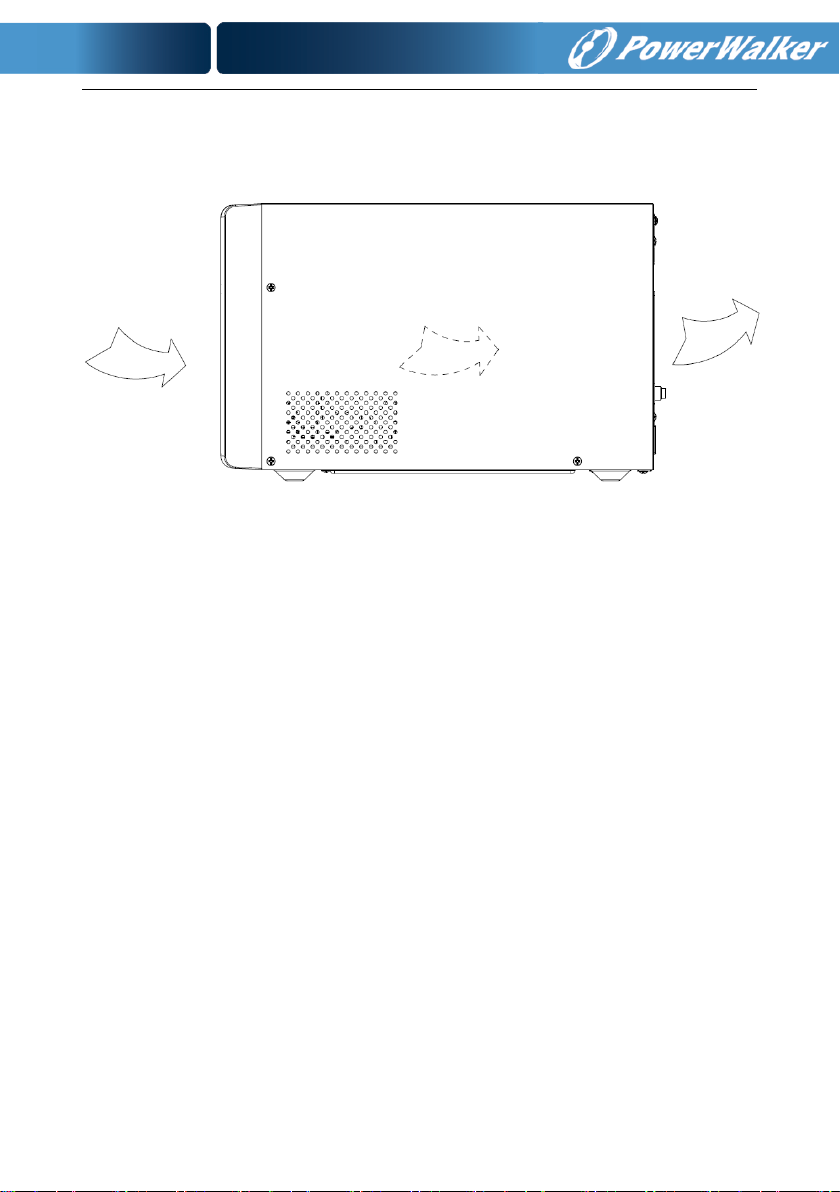
★ Do not block ventilation openings on the UPS’s housing. Ensure
the air vents on the front, side and rear of the UPS are not blocked.
-2-
Recommended at least 25cm of space on each side. The air flow
diagram is shown as below:
■ Figure 1.1 The Air Flow Diagram
★ This UPS receives power from more than one
source-disconnection of AC source and the DC source is required
to de-energize this unit before servicing.
1.2 Operation
★ For safety consideration, do not disconnect the mains cable on the
UPS or the building wiring socket (grounded shockproof socket)
during operation, the grounding for the UPS and all loads
connected will be disconnected.
★ The UPS features its own, internal current source (batteries). You
may be electric shocked when you touch the UPS output sockets
or output terminal block even if the UPS is not connected to the
building wiring socket.
★ In order to fully disconnect the UPS, first press the OFF button to
turn off the UPS, and then disconnect the mains lead.
★ Ensure that no liquid or other external objects can enter the UPS.
★ Do not remove the enclosure. This system is to be serviced by
qualified service personnel only. There are NO USER

-3-
SERVICEABLE PARTS inside the UPS.
★ Remove the protective panel only after disconnecting the terminal
connections.
1.3 Maintenance, servicing and faults
★ The UPS operates with hazardous voltages. Repairs may be
carried out only by qualified maintenance personnel.
★ Caution - risk of electric shock. Even after the unit is disconnected
from the mains power supply (building wiring socket), components
inside the UPS are still connected to the battery which are
potentially dangerous.
★ Before carrying out any kind of service and/or maintenance,
disconnect the batteries. Verify that no current is present and no
hazardous voltage exists in the capacitor or BUS capacitor
terminals.
★ Batteries must be replaced only by qualified personnel.
★ Caution - risk of electric shock. The battery circuit is not isolated
from the input voltage. Hazardous voltages may occur between the
battery terminals and the ground. Verify that no voltage is present
before servicing!
★ Batteries have a high short-circuit current and pose a risk of shock.
Take all precautionary measures specified below and any other
measures necessary when working with batteries:
- remove all jewellery, wristwatches, rings and other metal objects
- use only tools with insulated grips and handles.
- Wear rubber gloves and boots.
- Do not lay tools or metal parts on top of batteries.
- Disconnect the charging source prior to connecting or
disconnecting battery terminals.
★ When changing batteries, replace with the same quantity and the
same type of batteries.
★ Do not attempt to dispose of batteries by burning them. It could

-4-
cause explosion.
★ Do not open or destroy batteries. Effluent electrolyte can cause
injury to the skin and eyes. It may be toxic.
★ Please replace the fuse only by a fuse of the same type and of the
same amperage in order to avoid fire hazards.
★ Do not dismantle the UPS, except the qualified maintenance
personnel.
1.4 Transport
★ Please transport the UPS only in the original packaging (to protect
against shock and impact).
1.5 Storage
★ The UPS must be stockpiled in the room where it is ventilated and
dry.
-5-
1.6 Standards
* Safety
IEC/EN 62040-1:2008+A1:2013
* EMI
Conducted Emission................................:IEC/EN 62040-2
Category C2
Radiated Emission...................................:IEC/EN 62040-2
Category C2
Harmonic Current...................................:IEC/EN 61000-3-2
Voltage Fluctuation and Flicker...............:IEC/EN 61000-3-3
*EMS
ESD.......................................................:IEC/EN 61000-4-2
Level 3
RS.........................................................:IEC/EN 61000-4-3
Level 3
EFT........................................................:IEC/EN 61000-4-4
Level 4
SURGE..................................................:IEC/EN 61000-4-5
Level 3&4
CS………………………………….……...:IEC/EN 61000-4-6
Level 3
MS………………………………………..: IEC/EN 61000-4-8
Level 3
Voltage Dips……………………...….....: IEC/EN 61000-4-11
Low Frequency Signals..........................:IEC/EN 61000-2-2
-6-
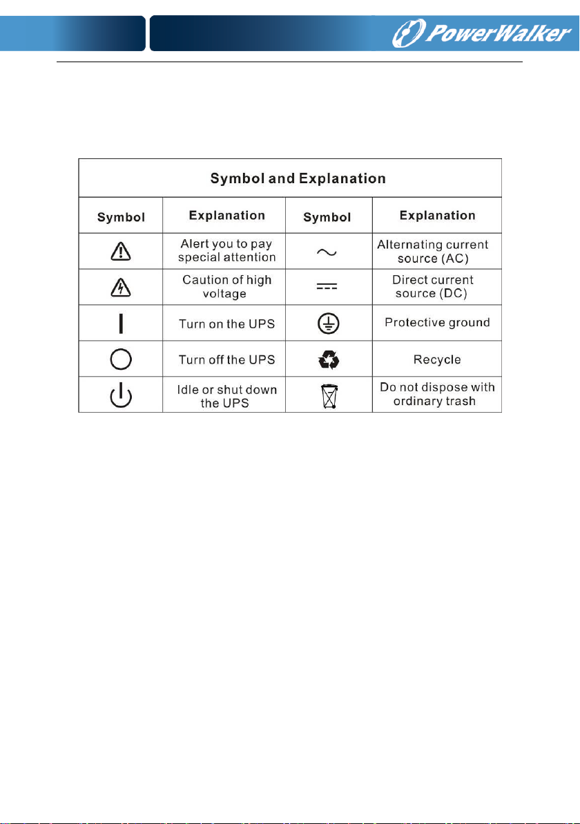
2. Description of Commonly Used Symbols
Some or all of the following symbols may be used in this manual. It is
advisable to familiarize yourself with them and understand their meaning:
-7-
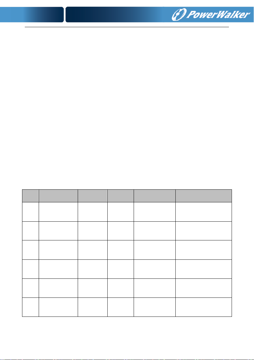
Item
Model name
Power
Rating
Model
type
Model
description
Other
1
VFI 1000 TG
1000VA
900W
Tower
Standard
model
Single Phase input
Single Phase
Output
2
VFI 1000 TGS
1000VA
900W
Tower
Long Backup
time model
Single Phase input
Single Phase
Output
3
VFI 2000 TG
2000VA
1800W
Tower
Standard
model
Single Phase input
Single Phase
Output
4
VFI 2000 TGS
2000VA
1800W
Tower
Long Backup
time model
Single Phase input
Single Phase
Output
5
VFI 3000 TG
3000VA
2700W
Tower
Standard
model
Single Phase input
Single Phase
Output
6
VFI 3000 TGS
3000VA
2700W
Tower
Long Backup
time model
Single Phase input
Single Phase
Output
3. Introduction
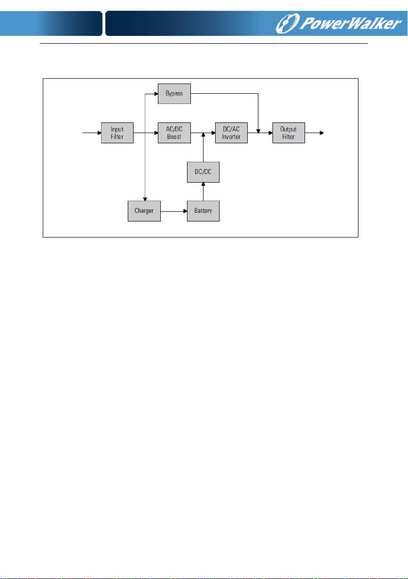
This On-Line-Series is an uninterruptible power supply incorporating
double-converter technology. It provides perfect protection specifically for
Linux, UNIX, and Windows servers.
The double-converter principle eliminates all mains power disturbances. A
rectifier converts the alternating current from the socket outlet to direct
current. This direct current charges the batteries and powers the inverter.
On the basis of this DC voltage, the inverter generates a sinusoidal AC
voltage, which permanently supplies the loads.
Computers and periphery are thus powered entirely by the mains voltage.
In the event of power failure, the maintenance-free batteries power the
inverter.
This manual covers the UPS listed as follows. Please confirm whether it is
the model you intend to purchase by performing a visual inspection of the
Model No. on the rear panel of the UPS.
The Model List
-8-
UPS Block Diagram
-9-
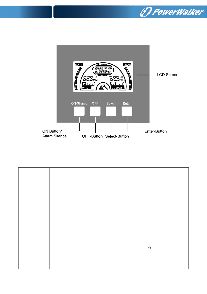
Switch
Function
ON/Silence
Button
Turn on UPS system:
By pressing the ON-Button continuously for more than 1 second the
UPS system is turned on.
Deactivate acoustic alarm:
By pressing this Button an acoustic alarm can be deactivated in the
battery mode.
By short touch this Button all acoustic alarms can be deactivated in
all modes.
Do the battery test:
By pressing this Button the UPS can do the battery test in the Line
mode or ECO mode or CVCF mode.
OFF
Button
When mains power is normal, the UPS system switches to No
output or Bypass mode by pressing OFF-Button “ “, and the inverter
is off. At this moment, if Bypass is enabled, then the output sockets
are supplied with voltage via the bypass if the mains power is
available.
4. Panel Description
The display panel of 1000-3000 TG(S) is the same, which is shown as
below:
■ Figure 4.1 The Display Panel
4.1 Button

-10-
Deactivate acoustic alarm:
By pressing this Button an acoustic alarm can be deactivated in the
bypass mode.
Release the UPS from fault mode and EPO status.
Select
Button
The output voltage, frequency, Bypass disable/enable and operating
mode in No output or Bypass mode, Battery Ah, Battery remain time
display disable/enable and Charger current in all mode, could be
selected by pressing Select-Button, and confirmed by pressing
Enter-Button.
Enter
Button
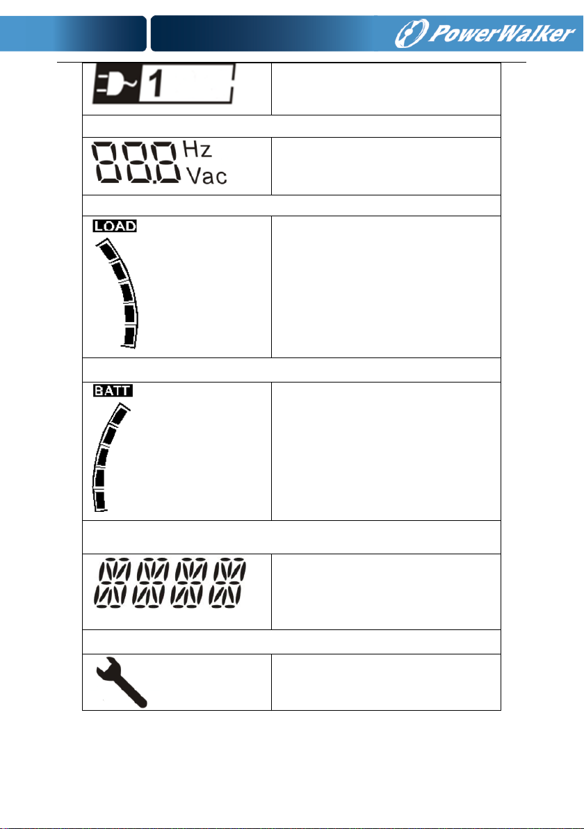
Display
Function
Input Information
It indicates input voltage/frequency
value, which are displayed alternately.
4.2 LCD description
■ Figure 4.2 The LCD Display
LCD icon Function
-11-
It indicates the input is connected with
mains, and the input power is single
phase input.
Output Information
It indicates output voltage/frequency
value, which are displayed alternately.
Load Information
It indicates the load level. Every grid
represents the level of 20%. One grid
would be displayed if the level is
0~20%
Battery Information
It indicates the battery capacity. Every
grid represents the capacity of 20%.
Mode/Fault/Warning Information
It Indicates the operating mode or
Fault kind or Warning kind or battery
remain time, several warning kinds at
the same time could be displayed
alternately.
Else
It indicates the UPS is in setting mode.
-12-
It indicates the UPS is in Fault mode or
has some warnings.
Normal operating mode
Code
No output mode
STbY
Bypass mode
bYPA
Line mode
LINE
Battery mode
bATT
Battery test mode
TEST
ECO mode
ECO
Converter mode
CVCF
LCD display in different mode
The different message/string would be displayed on the LCD screen
corresponding to their operating modes, and they are illustrated as the
following table. At any time, only one normal operating string or fault string
is presented, but the warning, if several warning happen at the same time,
they can be displayed on the LCD alternately. And the normal operating
mode string and the warning string would be shown circularly. Once one
fault is come forth, all previous warnings and the fault string would be shown
circularly.

-13-
Model No.
Output Socket
-SCHUKO(pcs)
Output Socket
-IEC(pcs)
VFI 1000 TG
3*Schuko
4*C13
The system may be installed and wired only by qualified
electricians in accordance with applicable safety regulations!
When installing the electrical wiring, please note the nominal
amperage of your incoming feeder.
5. Connection and Operation
5.1 Inspection:
Inspect the packaging carton and its contents for damage. Please
inform the transport agency immediately if you find signs of damage.
Please keep the packaging in a safe place for future use.
Note: To avoid any safety issue, please ensure that the incoming
feeder (mains) is isolated completely while whole installing
process.
5.2 Connection:
(1) UPS Input Connection
If the UPS is connected via the power cord, please use a proper
socket with protection against electric current, and pay attention to
the capacity of the socket. The UPS System has an input breaker on
the standard cabinet.
(2) UPS Output Connection
The output sockets and types of the UPS are shown below:

-14-
VFI 1000 TGS
2*Schuko
3*C13
VFI 2000 TG
4*Schuko
4*C13
VFI 2000 TGS
2*Schuko+1*C13
6*C13
VFI 3000 TG
4*Schuko
4*C13+1*C19
VFI 3000 TGS
2*Schuko+1*C19
3*C13+Terminal
block
(3) Battery Input Connection for long backup time model
When connecting the external batteries it’s recommended to pay
attention to these following items:
★ Use the battery pack with voltage:
24VDC for 1000 TG(S) (2 pcs of 12V batteries),
48VDC for 2000 TG(S) (4 pcs of 12V batteries),
72VDC for 3000 TG(S) (6 pcs of 12V batteries)
★ One Standard type battery connector on the rear panel is used for
★ The battery connection procedure is very important. Any incompliance
★ Prepare the battery cable with Standard type connector which should
★ If there is a battery breaker then turn it off first. Then connect the
★ Connect the input power cord of the UPS to mains power supply, the
Note: Connection of batteries more than or less than required will
cause abnormality or permanent damage.
connecting the battery pack.
may result in the risk of electric shock. Therefore, the following steps
must be strictly complied with.
be able to carry the current.
battery cable to the Standard type battery connector on the real panel.
battery would start to be charged.

-15-
The Caution!
A DC breaker must be connected between the UPS and external
battery if no used standard battery pack.
The Caution!
The output sockets of the UPS system may still be electrically live
even if the power supply system has been disconnected.
(4) EPO Connection:
EPO (Emergency Power Off) function is standard feature for
UPS, the polarity of EPO is configurable; EPO is normally
close as default setting. If the connection between two ports of
EPO connector is disconnected, EPO function will be active and
the UPS will stop output power immediately.
● Normally open
Normally EPO connector is open on the rear panel. Once the
connector is closed with a wire, the UPS will stop output until
EPO status is reset.
Disable EPO status Enable EPO status
● Normally close
Normally EPO connector is closed with a wire on the rear panel.
Once the connector is open, the UPS will stop output until EPO
status is disabled

-16-
Enable EPO status Disable EPO status
5.3 Battery recharge:
Fully charge the batteries (external) of the UPS system by leaving the
UPS system connected to the mains power for 1-2 hours approximately.
The UPS system is able to operate directly without recharging process,
but the backup time may be shorter than the nominal value specified.
5.4 Turn on the UPS:
(1) With mains power connecting:
Press On-button continuously for more than 1 second to turn on the
UPS, the UPS will get into the Line mode; the LCD screen will
indicate the state of the UPS.
(2) Without mains power connecting:
Even though mains power is not connected to the UPS, the UPS still
can be turned on by just simply pressing on button continuously for
more than 1 second with external batteries connected, the UPS will
get into the Battery mode, and the LCD screen will indicate the state
of the UPS.
Note: The default setting for bypass mode is no output after UPS
is connecting mains power and breaker is turned on. This can be
configurable.
5.5 Test function:
Test function is checking battery performance of the UPS system by
pressing the On-Switch for more than 1 second while UPS is operating
in Line mode, the UPS would detect whether the battery is connected
or the battery is weak. And the UPS could also implement this test
automatically and periodically, the period time is configurable.

-17-
5.6 Turn off the UPS:
(1) In Line Mode:
Press OFF button continuously for more than 1 second to turn off
the UPS, the UPS will get into no output or bypass mode. In
circumstance, the UPS might have output power if bypass mode is
enabled. Disconnect the mains power to turn off the output.
(2) In Battery Mode:
Press OFF button continuously for more than 1 second to turn off
the UPS, the UPS will get into no output or standby mode. After 10s
UPS will be shut down completely.
5.7 Audible alarm mute function:
If the audio alarm is too annoying in battery mode, the audio alarm is
able to mute by press ON button continuously for more than 1 second.
Moreover, the audio alarm will be active again when the battery
reaches low status for reminding that UPS output power will shut down
soon.
If the audio alarm is too annoying in bypass mode, the audio alarm is
able to mute by press OFF button continuously for more than 1 second.
This action doesn’t affect the warning and fault alarm.
In any mode, if the warning or fault alarm is too annoying, you can mute
it by press ON button less than 0.5 second, and enable it by press ON
button less than 0.5 second again. If the new warning or fault alarm is
appeared, the buzzer will beep again.
Alarm Table List

-18-
Warning
String
Site fail
SITE
Fan fail
FANF
Battery over voltage (over charged)
HIGH
Battery low
bLOW
Charge fail
CHGF
Inverter temperature high
TEPH
Battery open
bOPN
NO.
Status
Alarm
1
Battery mode
Beep once every 4 sec
2
Battery mode with
battery low
Beep once every sec
3
Bypass mode
Beep once every 2 min
4
Overload
Beep twice every sec
5
Warning active
(see Warning& Fault
Code Table )
Beep once every sec
6
Fault active
Beep continuously
7
Button function active
Beep once
6. Operating Mode for All Models
The different string could be displayed on the LCD screen corresponding to
their operating modes, and they are illustrated as the following table. At any
time, only one normal operating string or fault string is presented. But the
warning, even several warnings could appear in a certain normal operating
mode at one time. And the normal operating mode string and the warning
string would be shown circularly. Once one fault is come forth, then all
previous warnings would not be shown again but only the fault string is
presented.
Warning& Fault Code Table 6.1

-19-
Overload
OVLD
Digital bigger charger fail
dCHF
Inner temperature high
ITPH
Fault
String
Inverter short
SHOR
Overload fault
OVLD
Inverter soft start fail
ISFT
Bus soft start fail
bSFT
Over temperature fault
OVTP
Inverter Volt Low
INVL
Inverter Volt High
INVH
Bus volt over
bUSH
Bus volt Low
bUSL
Bus short
bUSS
Inverter NTC open
NTCO
Emergency Power Off
EPO
6.1 Line mode
The LCD display in Line mode is shown as figure6.1. The information
about the mains power, the battery level, the UPS output and the load
level will be displayed. The “LINE” string indicates UPS working in Line
mode.

-20-
■ Figure 6.1 The Line mode
6.2 Battery mode
The LCD display in battery mode is shown as figure6.2. The
information about the battery voltage, the battery level, the UPS output
and the load level will be displayed. The “bATT” string indicates UPS
working in the battery mode. If the function of battery remain time is
set to enable, the “bATT” string and battery remaining time (in unit Min
or Sec) would display in turn every 2s.
When the UPS is running in battery mode, the buzzer beeps once
every 4 seconds. If the “ON” button on the front panel is pressed for
more than 1 second, the buzzer will stop beeping (in silence mode).
Press the “ON” button once again for more than 1 second to resume
the alarm function.
■ Figure 6.2 The Battery mode

-21-
6.3 Bypass mode
The LCD display in bypass mode is shown as figure6.3. The
information about the mains power, the battery level, the UPS output
and the load level will be displayed. The UPS will beep once every 2
minutes in bypass mode. The “bYPA” string indicates UPS working in
the bypass mode
■ Figure 6.3 The Bypass mode
6.4 No Output mode
The LCD display in No output mode is shown as figure6.4. The
information about the mains power, the battery level, the UPS output
and the load level could be displayed. The “STbY” string indicates
UPS working in the No output mode.
■ Figure 6.4 The No output mode

-22-
6.5 EPO (Emergency Power Off)
It is also called RPO (Remote Power Off). On LCD display, the word of
“EPO” will be presented in the position of output voltage.
It is a special status which the UPS will shut the output off and send out
alarm. The UPS cannot be turned off by pressing “OFF” button on the
panel, only after resetting EPO status.
6.6 ECO mode (Economy mode)
It is also called high efficiency mode. After turning UPS on in ECO mode,
the output power will be supplied from mains power directly via internal
filter while the mains power is in certain range, so the high efficiency
performance would be gained in ECO mode. Once the mains power is
loss or out of range, the UPS will transfer to battery mode and the load
will be supplied continuously by the battery.
1) ECO mode can be enabled through the LCD setting or the software
(Winpower, etc.).
2) The transfer time of UPS output from ECO mode to battery mode is
less than 10ms. It is suggested that takes account of application for
some sensitive load.
6.7 CVCF mode
CVCF (Constant Voltage Constant Frequency) which is also called
converter mode, UPS would works in frequency free-run with fixed
output frequency (50Hz or 60Hz). Once the mains are loss or abnormal,
the UPS would transfer to battery mode and the load is supplied
continuously by the battery.
1) CVCF mode can be enabled through the LCD setting or the software
(Winpower, etc.).
2) The normal power rating will be derating to 60% in converter mode.

-23-
6.8 Abnormal mode
In abnormal mode such as Bus fault etc., the corresponding fault string
would be shown on LCD display to indicate the status of the UPS, and
the background light will become red color. For example “SHOR” would
be shown when the connected load or the UPS output is in
short-circuited, the LCD display is shown as figure6.5 followings.
■ Figure 6.5 The Fault mode
7. Setting by LCD Module
The output voltage/frequency, Auto bypass status, operating mode in No
output mode or Bypass mode, charger current, external Battery AH and
battery remaining time function in all mode could be set directly through
LCD module.
In bypass or no output mode, pressing the “Enter” button on the LCD panel
for more than 1 second to enter setting mode. The LCD display is shown in
the following figure7.1. The string “OPV” that stands for output voltage.
“230Vac” indicates the existing output voltage is 230Vac. if you want to set
output voltage, press the “Enter” button for more than 1 second, a flickering
string “220” would be shown, if the “Enter” button is pressed again, the
string “220” turn to flickerless, the output volt is changed to 220V; if the
“Select” button is pressed for more than 1 second, the next flickering string
“230” appear, the order of flickering string is 220 – 230 – 240 – 220 – 230,

-24-
Press “Enter” button to confirm the output volt what you want.
■ Figure 7.1 Setting by LCD
To exit the setting mode that requests a pressing once on the “Enter” button;
to continue setting, press “Select” button. If no any pressing on the “Select”
or “Enter” button lasting for more than 10 seconds, the setting mode will exit
automatically.
The output frequency string “OPF”, Bypass status string ” bYPA”, operating
mode string “MOdE”, External Battery Ah string “EbAH”, battery remaining
time string “bATT” , Charger current string”CHG” would be presented
circularly. The only one voltage value can be selected in “220V”, “230V”,
“240V” at any time; The only one frequency value can be selected in “50Hz”,
“60Hz” at any time; Bypass status can be selected in “000” or “001”(Here
000 means Bypass Disable,001 means Bypass Enable),The UPS would
turn to bypass mode in several seconds if “Bypass Enable” is selected, and
turn to no output mode in several seconds if “Bypass Disable” is selected;
Operating mode can be selected in “UPS”, “ECO”, “CVF”(Here “UPS”
means the normal online mode, “ECO” means the high efficiency mode, and
“CVF” means the converter mode), The mode change would be active only
after the UPS is turned on; External Battery Ah could be selected from “005”
to “300”(Here “005” means 5Ah total external battery); Charger Current
could be selected 3.0/6.0 for 1KL T and 1.5/3.0/4.5/6.0 for 2KL/3KL T
(Here 3.0 means 3A charger). The battery remaining time function could be
selected in “000” or “001”. (Here 000 means battery remaining time function
is disabled, then the battery remaining time could not display on LCD in

-25-
Step 1: “OPV” after pressing the “Enter” button.
Step 2: “OPF” after pressing the “Select” button.
battery mode. 001 means battery remaining time function is enabled, then in
battery mode or battery test mode the battery remaining time (in unit Min or
Sec) and string “bATT” would display on LCD in turn every 2s).
■ An example for changing the Operating mode from normal mode to
converter mode through the LCD display.

-26-
Step 3: “bYPA” after pressing the “Select” button.
Step 4: “MOdE” after pressing the “Select” button.
“UPS” is flickering after pressing the “Enter” button.
Step 5: “ECO” flickering after pressing the “Select” button.

-27-
Step 6: “CVF” flickering after pressing the “Select” button. Press
the “Enter” button
Short touch “Enter” button exit setting mode.
 Loading...