

Page 1
Online UPS
owerWalker VFI 10000TCP 3/1
P
PowerWalker VFI 10000TP 3/1
PowerWalker VFI 20000TP 3/1
Manual
EN/DE
Uninterruptible Power Supply System
Page 2

CONTENT:
1. Safety ........................................................................................................... 1
1.1 Installation............................................................................................... 1
1.2 Operation ................................................................................................ 2
1.3 Maintenance, Servicing and Faults ........................................................ 3
1.4 Transport ................................................................................................ 4
1.5 Storage ................................................................................................... 4
1.6 Standards ............................................................................................... 5
2. Description of Commonly Used Symbols ................................................ 6
3. Introduction ................................................................................................. 7
3.1 System and Model Description ............................................................... 7
3.2 Product Specification and Performance ............................................... 10
4. Installation ................................................................................................. 13
4.1 Unpacking and Inspection .................................................................... 13
4.2 Input and Output Power Cords and Protective Earth Ground
Installation ................................................................................................... 16
4.3 Operating Procedure for Connecting with The External Battery .......... 21
5. Operation ................................................................................................... 23
5.1 Display Panel ........................................................................................ 23
5.2 Operating Mode .................................................................................... 27
5.3 Turning On and Turning Off UPS ......................................................... 29
5.4 LCD Operation ...................................................................................... 31
6. Special function ........................................................................................ 40
6.1 HE Function .......................................................................................... 40
Page 3

6.2 Converter Function ............................................................................... 40
6.3 Parallel Function ................................................................................... 41
6.4 PowerWalker VFI 10000TCP 3/1 Optional Design of Charger Current 47
6.5 Backfeed Protection ............................................................................. 48
7. Trouble Shooting ...................................................................................... 51
7.1 Trouble Shooting According To Warning Indication .............................. 51
7.2 Trouble Shooting According To Fault Indication ................................... 53
7.3 Trouble Shooting In Else Cases ........................................................... 54
8. Battery Maintenance, Replacement and Disposal ................................. 56
8.1 Maintenance ......................................................................................... 56
8.2 Replacement and Disposal of Batteries ............................................... 57
9. Communication Port................................................................................. 60
9.1 RS232&USB Interface .......................................................................... 60
9.2 Intelligent Slot ....................................................................................... 60
9.3 AS400 Interface (Option) ...................................................................... 60
10. Software Installation ..................................... Error! Bookmark not defined.
Page 4

1. Safety
Please read carefully the following user manual and the safety
instructions before installing the unit or using the unit!
1.1 Installation
★ Condensation may occur if the UPS is moved directly from a
cold to a warm environment. The UPS must be absolutely dry
before being installed. Please allow an acclimatization time of
at least two hours.
★ Do not install the UPS near water or in damp environment.
★ Do not install the UPS where it would be exposed to direct
sunlight or near heat.
★ Do not block ventilation openings in the UPS’s housing.
★ Do not connect appliances or items of e quipment w hi ch would
overload the UPS (e.g. laser printers, etc) to the UPS output.
★ Place cables in such a way that no one can step on or trip over
them.
★ UPS has provided earthed terminal, in the final installed
system configuration, equipotential earth bonding to the
external UPS battery cabinets.
★ An integral single emergency switching device which prevents
further supply to the load by the UPS in any mode of operation
should be provided in the building wiring installation.
1
Page 5

★ An appropriate disconnect device as short-circuit backup
protection should be provided in the building wiring
installation.
★ For thre e-phase equipmen t connection to an IT power syste m,
a four-pole device which disconnect all phase conductors and
the neutral conductor should be provided in the buil ding wiring
installation.
★ This is permanently connected equipment, it must be installed
by qualified maintenance personnel.
★ Earth connection essential before connecting to the building
wiring terminal.
1.2 Operation
★ Do not disconnect the ea rth con ductor ca ble on the UPS or the
building wiring terminals in any time since this would cancel
the protective earthing of the UPS system and of all connected
loads.
★ The UPS output terminal block ma y be electrically liv ed eve n if
the UPS system is not connected to the building wiring
terminal.
★ In order to fully disconnect the UPS, turn the M1/M2/N input
breaker in the “OFF” position (for PowerWalker VFI
10000-20000 TP 3/1), turn the R/S/T/N input switch in the
“OFF” position (for PowerWalker VFI 10000TCP 3/1), then
disconnect the mains lead.
2
Page 6

★ Ensure that no liquid or other foreign objects can enter the
UPS.
1.3 Maintenance, servicing and faults
★ The UPS operates with hazardous voltages. Repairs should be
carried out only by qualified maintenance personnel.
★ Caution - risk of electric shock. Even after the unit is
disconnected from the mains power supply (building wiring
terminal), components inside the UPS are still c onnected to the
battery which are potentially dangerous.
★ Before carrying out any kind of service and/or maintenance,
please disconnect the batteries. Verify that no current is
present and no hazardous voltage exists in the capacitor or
BUS capacitor terminals.
★ Batteries must be replaced only by qualified personnel.
★ Caution - risk of electric shock. The battery circuit is not
isolated from the in put v oltage. Hazardous v oltages may occu r
between the battery terminals and the ground. Verify that no
voltage is present before servicing!
★ Batteri es have a high shor t-circuit current and pose a risk of
shock. Take all precautionary measures specified below and
any other measures necessary when working with batteries:
- remove all jewellery, wristwatches, rings and other metal
objects
3
Page 7

- use only tools with insulated grips and handles.
★ When changing batteries, replace with the same quantity and
the same type of batteries.
★ Do not attempt to dispose of batteries by burning them. It
could cause explosion.
★ Do not open or destroy batteries. Effluent electrolyte can cause
injury to the skin and eyes. It may be toxic.
★ Please replace the fuse only by a fuse of the same type and of
the same amperage in order to avoid fire hazards.
★ Do not dismantle the UPS, except the qualified maintenance
personnel.
1.4 Transport
★ Please transport the UPS only in the original packaging (to
protect against shock and impact).
1.5 Storage
★ The UPS m ust be stockpiled in the room w here it is ventilated
and dry.
4
Page 8
* Safety
IEC/EN 62040-1
*EMS
ESD........................................:IEC/EN 61000-4-2
Level 3
RS..........................................:IEC/EN 61000-4-3
Level 3
EFT.........................................:IEC/EN 61000-4-4
Level 4
SURGE....................................:IEC/EN 61000-4-5
Level 4
Low Frequency Signals .............:IEC/EN 61000-2-2
1.6 Standards
* EMI
Conducted Em i ss i on .. ...............:IEC/EN 62040-2 Category C3
Radiated Emission...................:IEC/EN 62040-2 Category C3
Warning: This is a product for c om mer cial and industrial application
in the second environment-installation restrictions or additional
measures may be needed to prevent disturbances.
5
Page 9
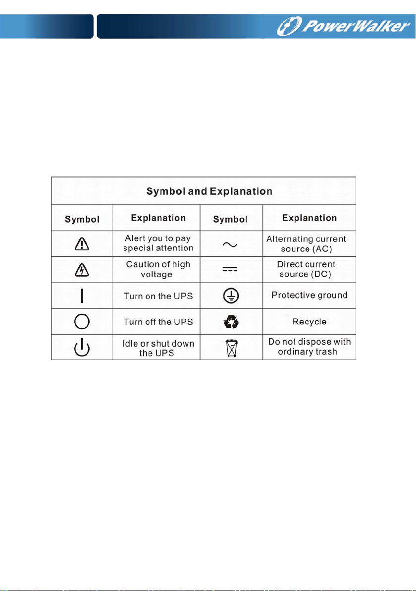
2. Description of Commonly Used Symbols
Some or all of the following symbols may be used in this manual. It is
advisable to familiarize yourself with them and understand their
meaning:
6
Page 10

3. Introduction
3.1 System and model description
This Online Series is an uninterruptible power supply incorporating
double-conversion technology. It provides perfect protection
specifically for computer equipment, communication systems to
computerized instruments.
Its true online double-conversion design eliminates all mains power
disturbances. A rectifier converts the alternating current from the
utility power to direct current. This direct current powers the inverte r.
On the basis of this DC voltage, the inverter generates a pure
sinusoidal AC voltage, which is constantly powering the loads.
Computers and Peripherals are thus powered entirely by the UPS. In
the event of power failure, the maintenance-free batteries power the
inverter.
This manual is applicable to the PowerWalker VFI 10000-20000 TP
3/1 models and PowerWalker VFI 10000T CP 3/1 model.
The tower 3-phase series UPS providing outstanding performance
and reliability, the UPS’s unique benefits include:
Online UPS design with pure sine wave output.
True online d ouble-conv ersion te chnolog y with hi gh power densit y,
utility frequency independence, and generator compatibility.
Overall high efficiency > 93%, saving the operating cost.
True three-phase power factor correction and high input power
factor (PF>0.99). Save the installation cost and reduce the
pollution back feed into upstream power system.
7
Page 11

High output power factor (0.9), to adapt more type load.
Intelligent Battery Management technology that uses advanced
battery management to increase battery service life, optimize
recharge time.
Selectable High Efficiency mode (ECO mode) or CVCF mode
operation.
Combo input (single phase or three phase) auto detection
Back-feed protection
Start-on-battery capability for powering up the UPS even if utility
power is not available.
Standard communication options: one RS-232 communication port,
one USB communi cation port.
Optional connectivity cards with enhanced communication
capabilities.
Remote shutdown control through the Remote Power-off (RPO)
port.
For tower PowerWalker VF I 10000-20000 TP 3/1, Maintenances are
simplified by allowing the safe replacement of batteries without
powering down the UPS. But PowerWalker VFI 10000TCP 3/1 model
have no this function.
N+X parallel redundancy to increase the reliability and flexibility.
The max p ar a llel numb er is 4.
User-friendly LCD display and LED indicators.
For tower PowerWalker VFI 10000-20000 TP 3/1, easily battery
exchange or extension and ava ilable to exten d the ba ckup time. But
PowerWalker VFI 10000TCP 3/1 model have no this function.
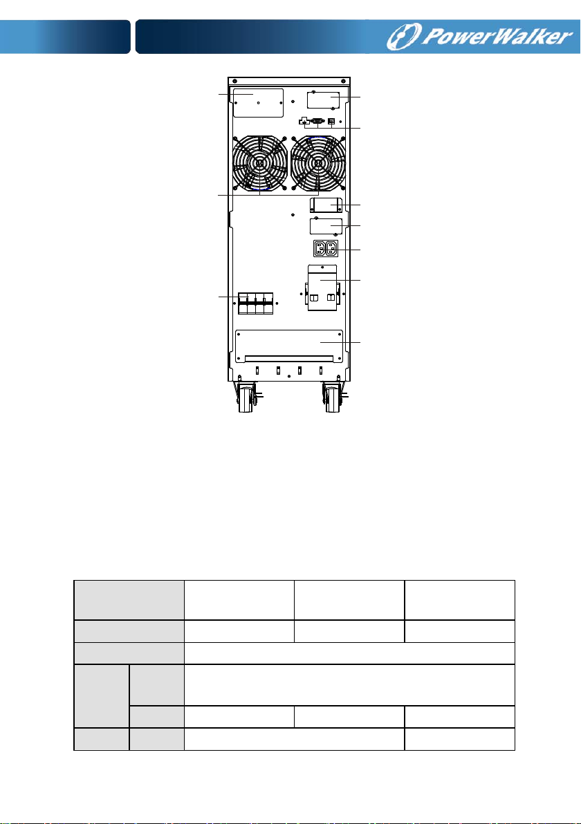
The appearance of tower 3-phase series
Refers to Fig. 3-1
8
Page 12
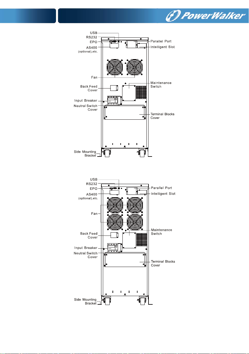
PowerW a lk er VFI 10000 TP 3/1 REAR VIEW
PowerWalker VFI 20000 TP 3/1 REAR VIEW
9
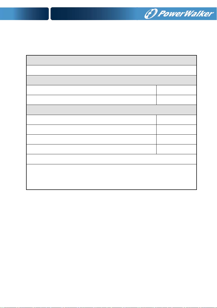
Page 13
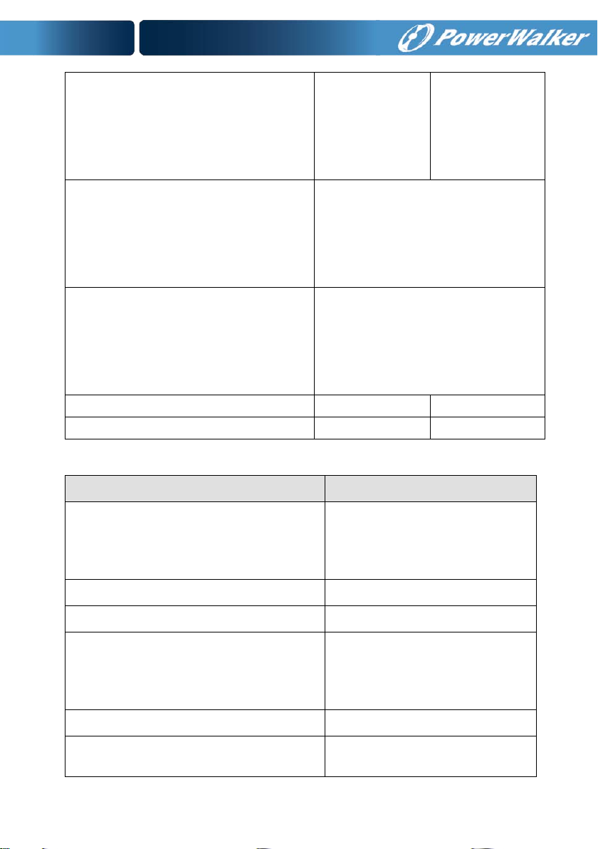
10000TP 3/1
20000TP 3/1
10000TCP 3/1
Power Rating
10KVA/9KW
20KVA/18KW
10KVA/9KW
Frequency (Hz)
50/60
Current
L1/L2/L3:23A MAX
L1/L2/L3:46A MAX
L1/L2/L3:23A MAX
Battery
Voltage
288VDC
240VDC
Parallel Port
(Optional)
Intelligent Slot
EPO、、RS232 USB
Fan
AS400
Input Breaker
Terminal Blocks
Cover
External Battery
IEC Connector
Maintenance and Output
Switch Cover
PowerWalker VFI 10000TCP 3/1 REAR VIEW
3.2 Product Specification an d Performance
1) General Sp e c i f ic ation
Input
Fig. 3-1 the rear view of the tower 3-phase series UPS
Model
Voltage (110-276)VAC (Depends on Load Level)
PowerWalker VFI
PowerWalker VFI
PowerWalker VFI
10
Page 14
Current
43A MAX
86A MAX
51.8A MAX
Voltage
200VAC/208VAC/220VAC/230VAC/ 240VAC*
3.5A/41.7A
7.0A/83.3A
3.5A/41.7A
(WxDxH) mm
Net Weight (kg)
127
188
85
Model
Voltage
Frequency
Power Factor
PowerWalker VFI
PowerWalker VFI
PowerWalker VFI
10000TCP 3/1
Output
Dimension
Current
45A/48.1A/45.5A/4
350x650x890 260*550*708
90A/96.2A/90.9A/8
45A/48.1A/45.5A/4
2) Electrical Performan c e
Input
10000TP 3/1
20000TP 3/1
Three-phase 50/60 Hz±10% >0.99(@Full load)
*:If output voltage be set 200V, output power will derating to 90% of power
rating
11
Page 15
Power
Output
Voltage
Regulation
±1% 0.9 lag
Power
Factor
Frequency
tolerance.
Synchronized
50/60Hz±10%
in Line mode
(AC mode)
±0.1% of
normal
frequency in
Battery mode
Distortion Overload capacity
100%-110% load
transfers to Bypass
mode after 5
minutes
THD<2%
Full load
(Linear
Load)/
<5% for
reference
non-linear
load
110%-130% load
transfers to Bypass
mode after 1
minutes
130%-150% load
transfers to Bypass
mode after 10
second
>150% load
transfers to Bypass
mode after 2 second
Current
crest ratio
3) Operating Environment
Temperature Humidity Altitude Storage temperature
0°C-45°C
<95% <1000m
-15°C-50°C
3:1
Note: if the UPS is installed or used in a place where the altitude is
above than 1000m, the output power must be derated in use, please
refer to the following:
Altitude (M) 1000 1500 2000 2500 3000 3500 4000 4500 5000
Maximum
100% 95% 91% 86% 82% 78% 74% 70% 67%
12
Page 16

4. Installation
The system may be installed and wired only by qualified
electricians in accordance wit h applicable safety regulations!
4.1 Unpacking and Inspection
1. Moving to th e in stallation site
The tower 3-phase series UPS has wheels making it easy to move the
UPS to the installation site after it has been unpacked. However, if the
receiving area is far from the installation site, we recommend you to
move the UPS by using a pallet jack or a lifter before you start to
unpack the UPS.
2. Unpacking and inspection
1) At the installation site, the utmost care shall be taken when
removing t he pac kaging i n o rder to a voi d damagi ng t he equi pment.
Check all packaging materials to ensure that no items are missing.
The shipping package contains:
● A UPS
● A user manual
● A communication cable
● Parallel port cover plate
13
Page 17
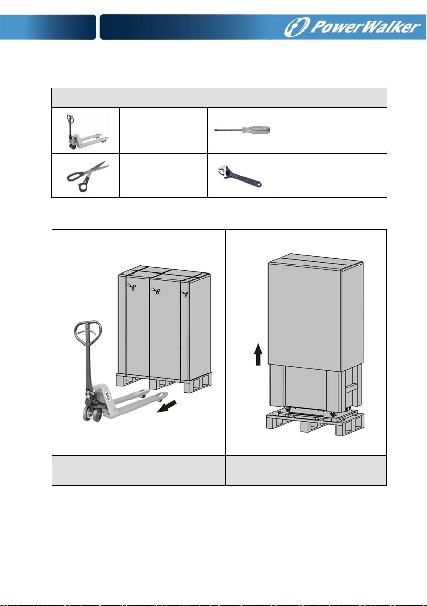
Tools kit
Remove the packa ging foll owing t he seque nce illustrated in Fig. 4-1 to
Fig. 4-4. (only for PowerWalker VFI 10000-20000 TP 3/1)
Lifter
Scissors
Phillips screwdriver
Wrench
Fig. 4-1 Unpacking-step1 Fig. 4-2 Unpacking-step2
14
Page 18
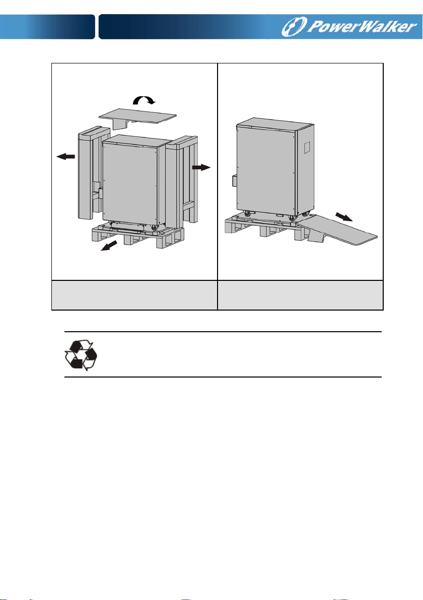
Fig. 4-3 Unpacking-step3 Fig. 4-4 Unpacking-step4
The shipping materials are recyclable. After unpacking,
save them for later use or dispose of them appropriately.
2) Inspect the appearance of the UPS to see if there is any damage
during transportation. Do not turn on the unit and notify the carrier
and dealer immediately if there is any damage or lacking of some
parts.
15
Page 19
4.2 Input and Output Power Cords and Protective
Earth Ground Installation
1. Notes for installation
1) The UPS must be installed in a location with good ventilation, far
away from water, inflammable gas and corrosive agents.
2) Ensure the air vents on the front and rear of the UPS are not
blocked. Allow at least 0.5m of space on each side.
3) Condensation to water drops may occur if the UPS is unpa cked in a
very low temperature environment. In this case it is necessary to
wait until the UPS is fully dried inside out before proceeding
installation and use. Other wi se t here are hazards of electric sh oc k .
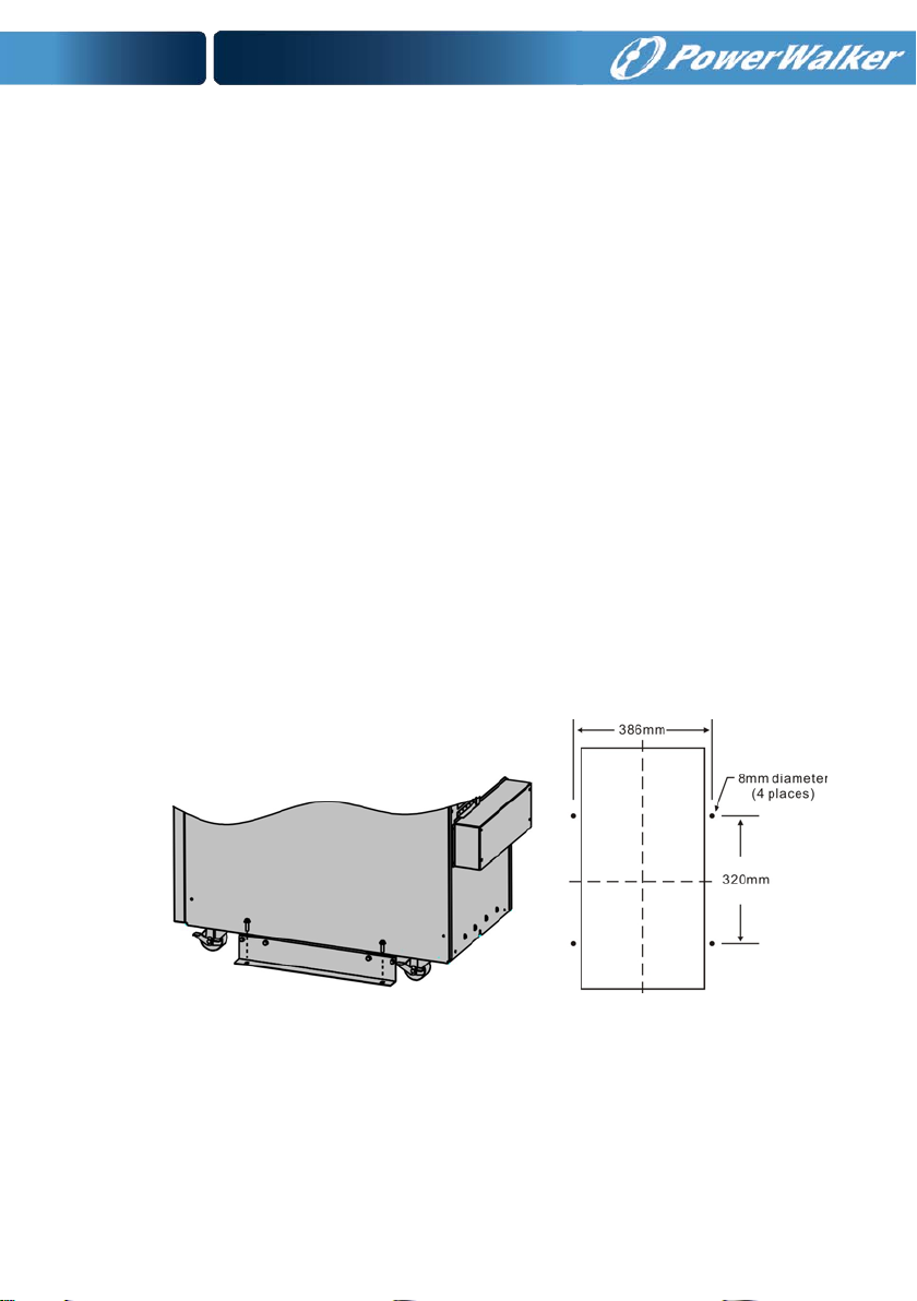
4) Once the installation is completed, the side mounting brackets
(used in shipping)shall be fixed back to ensure the sta bility of the
UPS enclosure. If impossible, additional stability can be added by
anchoring the mounting br ackets to the floor with M8 bolts. See Fig.
4-5. (only for PowerWalker VFI 10000-20000 TP 3/1)
Fig. 4-5 Additional stability
2. Installa t ion
Installation and wiring must be performed in accordance with the
local electric code and the following instructions by professional
personnel.
16
Page 20

For safety, please cut off the mains power switch before installation.
1) Op en the terminal block cover located on the rear panel of the
UPS, please refer to the appearance diagram.
2) For tower PowerWalker VFI 10000TCP 3/1 UPS, it is
recommended to select the UL1015 8AWG(10mm
2
) wire or other
insulated wire which complies with AWG Standard for the UPS
input and output wirings.
3) For PowerWalker VFI 20000TP 3/ 1 U PS, it is recommended to
select the UL1015 6AWG(25mm
2
) wire or other insulated wire
which complies with AW G Standa rd f or the UPS in put and out put
wirings.
Note: Do not use the wall receptacle as the input power source
for the UPS, as its rated current is less than the UPS’s
maximum input current. O therwise t he receptacle m ay be
burned and destroyed.
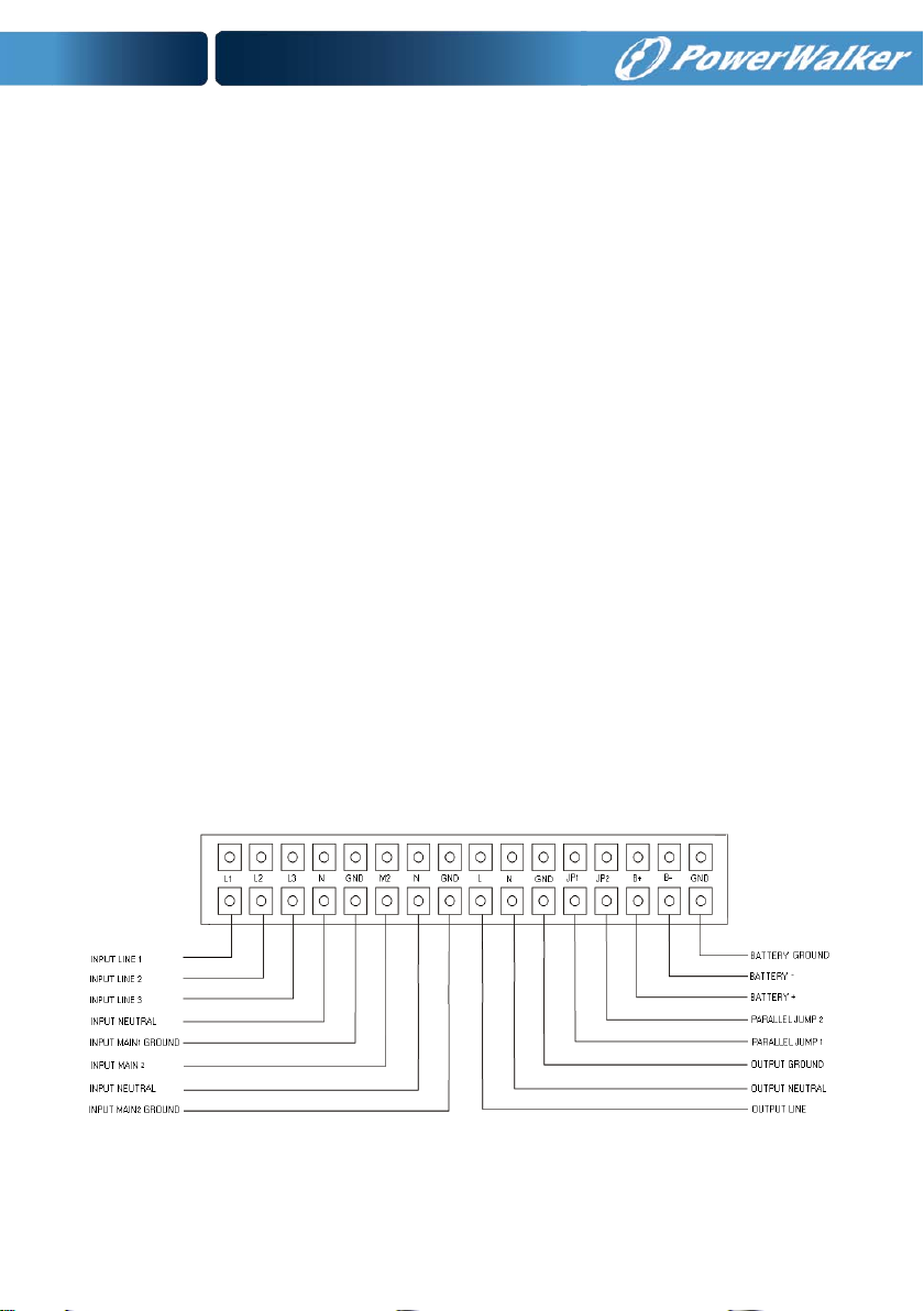
4) C onnect the input and output wires to the corresponding input
and output terminals according to the following diagram.
Note: you must make sure that the input and output wir es and
the input and output terminals are connected tightly.
5) The protective earth ground wire refers to the wire connection
between the equipment which consumes electri c eq uipment an d
the ground wire. The wire diameter of protective earth ground
wire should be at least as above mentioned for each model and
green wire or green wire with yellow ribbon wire is used.
6) A fter having completed the installation, make sure the wiring is
correct.
7) P lease install the output breaker between the output terminal
and the load, and the breaker should with leakage current
protective function if necessary.
17
Page 21
8) To connect the load with the UPS, please turn off all the loads
first, then perform the connection and finally turn on the loads
one by one.
9) No matter the UPS is connected to the utility power or not, the
output of the UPS may have electricity. The parts inside the unit
may still have hazardous voltage after turning off the UPS. To
make the UPS have no output, power off the UPS, and then
disconnect the utility power supply.
10) Suggest charging the batteries for 8 hours before use. After
connection, turn the M1/M2/N input breaker (for PowerWalker
VFI 10000-20000TP 3/1), turn the input switch (for PowerWalker
VFI 10000TCP 3/1 ) in the "ON" position, the UPS wil l cha r ge the
batteries automatically. You can also use the UPS immediately
without charging the batt eries first, but the backup time may be
less than the standard value.
11) If it is necessary to connect the inductance load such as a
monitor or a laser printer to the UPS, the start-up power should
be used for calculating the capacity of the UPS, as its start-up
power consumption is too big when it is started.
PowerW a lk er VFI 10000-20000TP 3/1
18
Page 22
10000TP 3/1
20000TP 3/1
Max.conducto r cross se ct io n[ mm2]
4
10
Input L1,L2,L3 breaker (A)
40A,250VAC
60A,250VAC
Max.conducto r cross se ct io n[ mm2]
13
25
Input M2 breaker (A)
63A,250VAC
100A,250VAC
Input fuse (A)
30A,250VAC
50A,690AC
Max.conducto r cross se ct io n[ mm2]
13
25
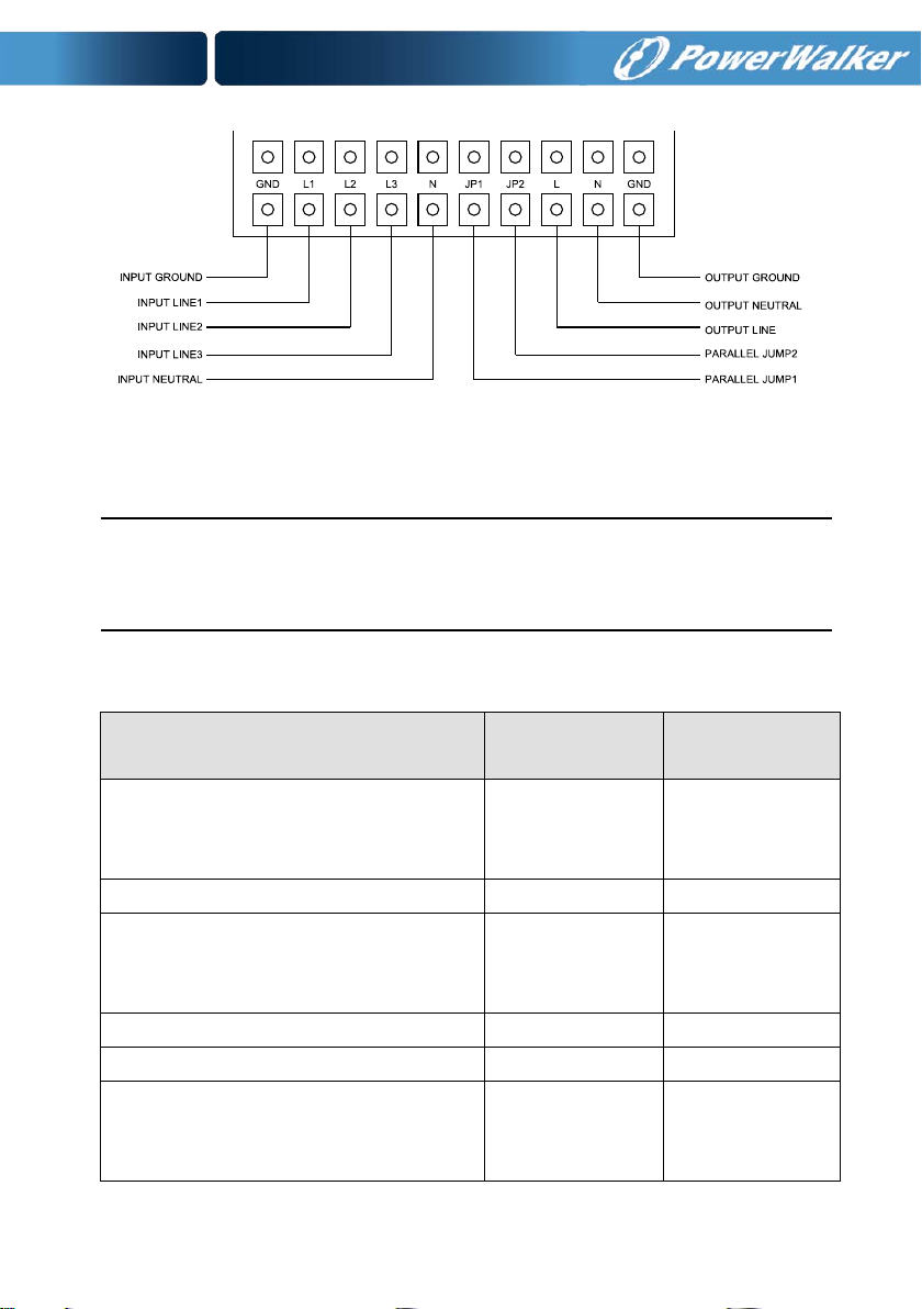
PowerWalker VFI 10000TCP 3/1 model
Fig. 4-6 Input and output Terminal Block wiring diagram
Important notes: If the UPS is used in single mode, JP1 and JP2 must
be connected. If the UPS is used in parallel mode, the J umper between
JP1 and JP2 must be removed.
Use cable cross section and protective device specification
Model PowerWalker VFI
Input L1,L2,L3
Min.conductor cross section[mm
Input N, M2
Min.conductor cross section[mm
Output L,N,
Min.conductor cross section[mm
2
2
2
]
]
]
19
2.5
10
10
PowerWalker VFI
6
21
21
Page 23
Max.conducto r cross se ct io n[ mm2]
13
25
protection in line input.
protection in line input.
Protective Earthing conductor[mm2]
Max.13
Max.25
Torque for fixing above terminals
(10 1b in)
(18 1b in)
External Battery Cabinet Positive
Pole(+),Neutral pole,Negative
pole(-),
Min.conductor cross section[mm
2
]
10
21
Line input Backfeed protection
device
M2 input Backfeed protect io n dev ice A 2-pole disconnection device with
A 4-pole disconnection device with
100A/250VAC, less than 15s break
time and min. 1.4mm clearance will be
used in final installation for backfeed
100A/250VAC, less than 15s break
time and min. 1.4mm clearance will be
used in final installation for backfeed
Sheet.1 PowerWalker VFI 10000-20000TP 3/1 models
Model PowerWa lk er VFI 10000TCP 3/1
Input L2,L3
Min.conductor cross section[mm2]
Max.conducto r cross se ct io n[ mm2]
Input L1,L2,L3,N switch (A) 63A,250VAC
2.5
4
Output switch(A)/maintain switch(A) 63A,250VAC
Input L1,N
Min.conductor cross section[mm2]
Max.conducto r cross se ct io n[ mm2]
Input fuse (A) 30A,250VAC
Output L,N,
10
13
20
Page 24

Min.conductor cross section[mm2]
10
Max.conducto r cross se ct io n[ mm2]
External Battery Cabinet Positive
Pole(+),Neutral pole,Negative
pole(-),
Min.conductor cross section[mm2]
Max.conducto r cross se ct io n[ mm2]
Protective Earthing conductor[mm2] MAX 13
Torque for fixing above terminals (10 1b in)
13
10
13
Sheet.2 PowerWalker VFI 10000TC P 3/1 model
4.3 Operating Procedure for Connecting with The
External Battery
1. For P owerWalk er VFI 10000-20000TP 3/1, The nominal DC voltage of
external battery pack is 288VDC. Each battery pack consists of 24
pieces of 12V maintenance free batteries in series. For PowerWalker
VFI 10000TC P 3/1 model, the nominal DC voltage of external batter y
pack is 240VDC. Each battery pack consists of 20 pieces of 12V
maintenance free batterie s in series ,To achieve longer backup time,
it is possible to connect multi-battery packs, but the principle of
“same voltage, same type” should be strictly followed.
2. For PowerWalker VFI 10000-20000TP 3/1, select the UL1015 8AWG
(10mm
2
)/6AWG ( 25mm2) wire respectively or other insulated wire
which complies with AWG Standard for the UPS battery wirings. The
procedure of installing bat tery bank should be c omplie d with strictly.
Otherwise you may encounter the hazardous of electric shock.
1) For tower 3/1 series if the UPS has internal bat tery pack, first of
all, disconnect the internal battery pack DC connectors.
21
Page 25
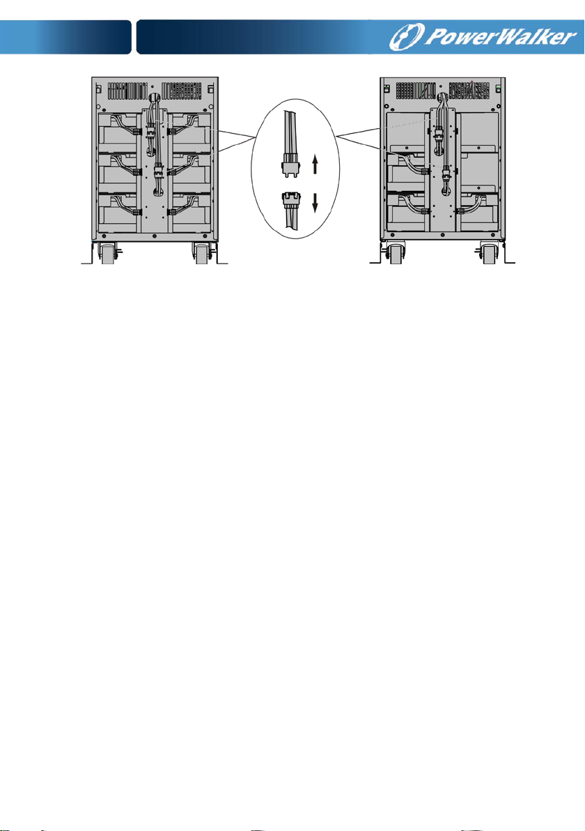
PowerWalker VFI 20000TP 3/1 PowerWalker VFI 10000TP 3/1
Fig. 4-7 Disconnect the internal battery pack DC connectors
2) A D C breaker mus t be connected between the external battery
pack and the UPS. The capacity of break er must be n ot less than
the data specified in the general specification.
3) Set the external battery pack breaker in “OFF” position and
connect the batteries (24 pieces for PowerWalker VFI
10000-20000TP 3/1, 20 pieces for PowerWalker VFI 10000TCP
3/1) in series.
4) For PowerW alke r VFI 10000-20000TP 3/1, Connect the external
battery pack to the battery terminals. For PowerWalker VFI
10000TCP 3/1 model, Connect the external battery pack to the
battery anderson connect or.
5) Reconnect the internal battery pack DC connectors, if you had
did step one.
3. Do not attempt to connect any loads to the UPS now. You should
connect the input power wire to t he right position first. And then set
the breaker of the battery pack in the “ON” position. After that set
the input breaker in the “ON” position. The UPS begins to charge the
battery packs at the time.
22
Page 26
5. Operation
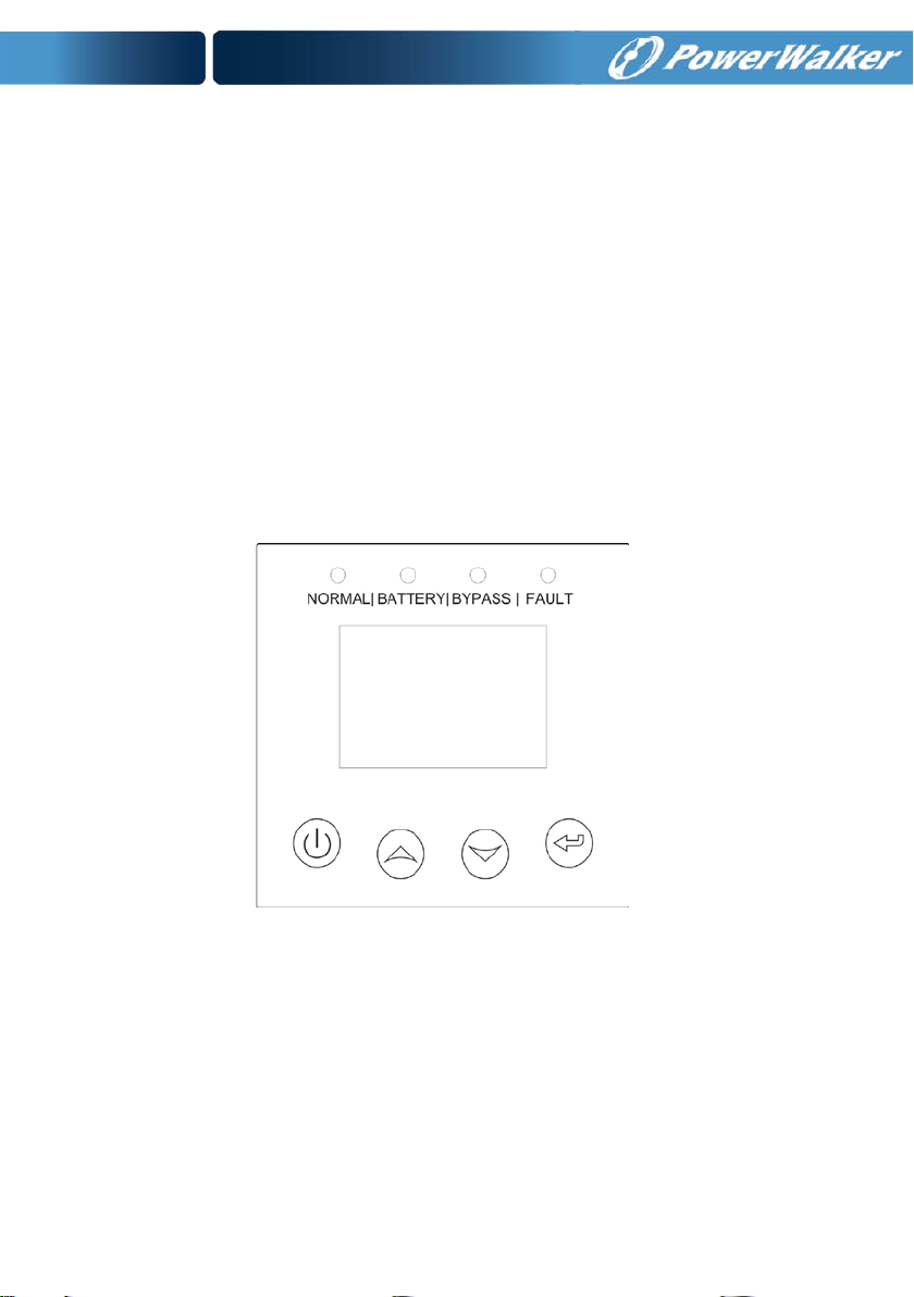
5.1 Display Panel
The UPS has a four-button graphical LCD with dual color backlight.
Standard back-li ght is used to light u p the display with w hite text and
a blue background. When the UPS has a critical alarm, the backlight
changes the text to dark amber and the backgrou nd to red. Besides
the graphical LCD, the UPS has four colorized LEDs to provide you
more convenient info.
See Figure Below
Fig. 5-1 PowerW a lk e r VFI 10000-20000TP 3/1/ PowerWalker VFI
10000TCP 3/1 UPS Control Panel
23
Page 27
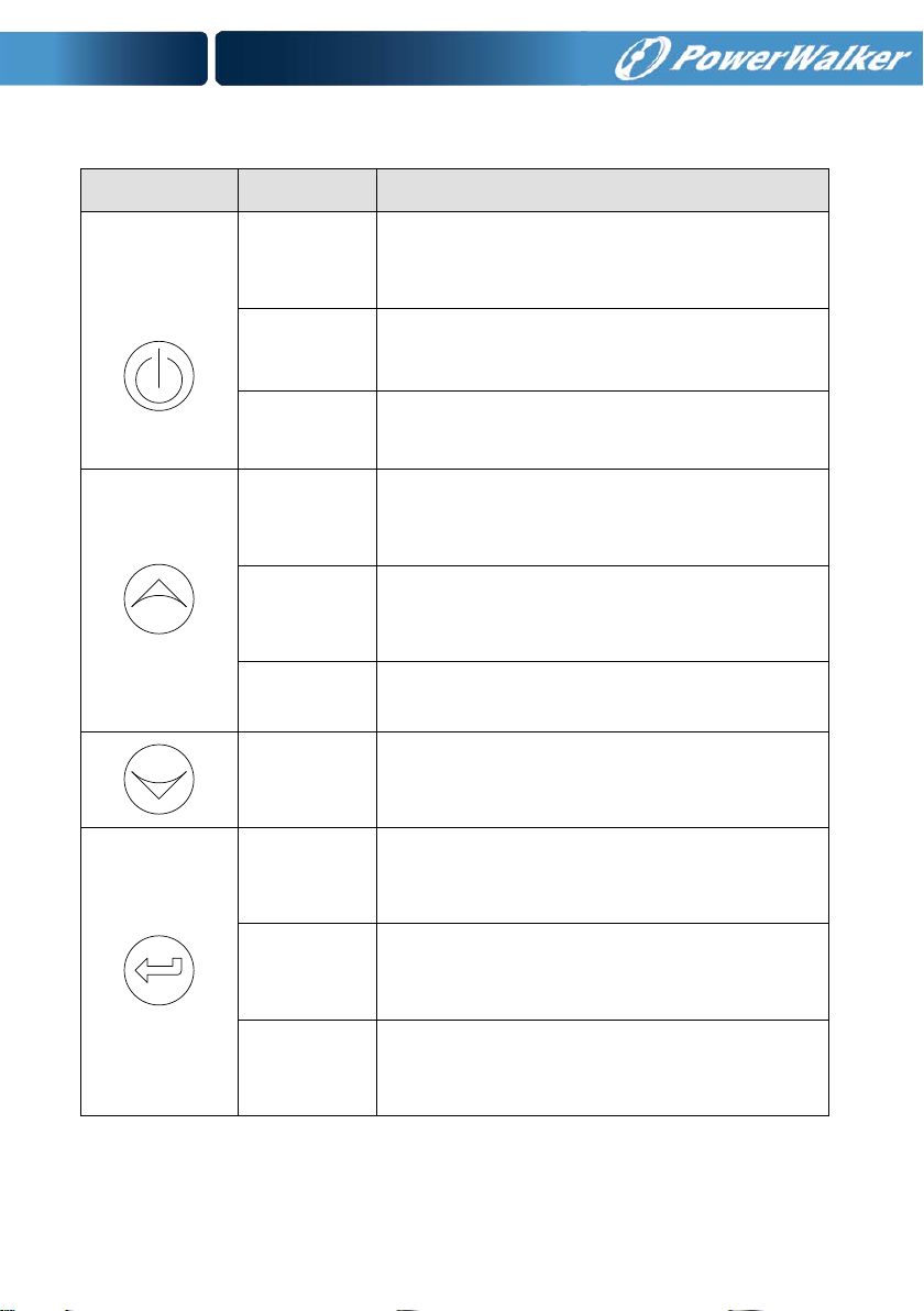
Table 5-1 Co n tr ol Button Functions
The Button Function Illustration
Power on
When the unit is no power and has connected
with battery, press this button for >100ms&<1s
to power on
Turn on
Turn off
Enter main
menu
Exit main
menu
Scroll up
Scroll down
Enter next
menu tree
When the unit is powered on and in Bypass
mode, press this button for >1s to turn on
When the unit has been turned on, press this
button for >3s to turn off
When displaying default UPS status summary
screen, press this button for >1s to enter the
main menu tree
Press this button for >1s to exit the present menu
to default system status display menu without
executing a command or changing a setting
Press this button for >100ms&<1s to scroll up the
menu option
Press this button for >100ms&<1s to scroll down
the menu option
Press this button for >100ms&<1s to select the
present menu option, or enter next menu, but do
not change any settin g
Press this button for >100ms&<1s to select the
present menu option, or enter next menu, but do
not change any setting
Press this button for >1s to confirm the edited
options and change the setting
Select one
menu option
Confirm the
present
setting
24
Page 28
(Green)
(Yellow)
(Yellow)
(Red)
with no output
with output
Table 5-2 LED definition
UPS state
Bypass mode
Bypass mode
Turning on
Line mode
Battery mode
HE mode
Battery test mode
Fault mode
Warning
Normal LED
△ △
●
●
●
●
△ △
↑ ↑
↑
Battery LED
△ △
△ △
Bypass LED
★
●
●
↑
Note:
●: Lightened constantly
△: #1-#4 Lightened circularly
★: Flashing
↑: Depended on the fault/warning status or other status
Fault LED
↑
↑
↑
↑
↑
●
★
Table 5-3 Buzzer definition
UPS condition Buzzer status
Fault active Continuous
Warning active Beep every second
Battery output
Bypass output Beep every 2 minutes
Beep every 4 seconds, if battery low, buzzer Beep every second
25
Page 29
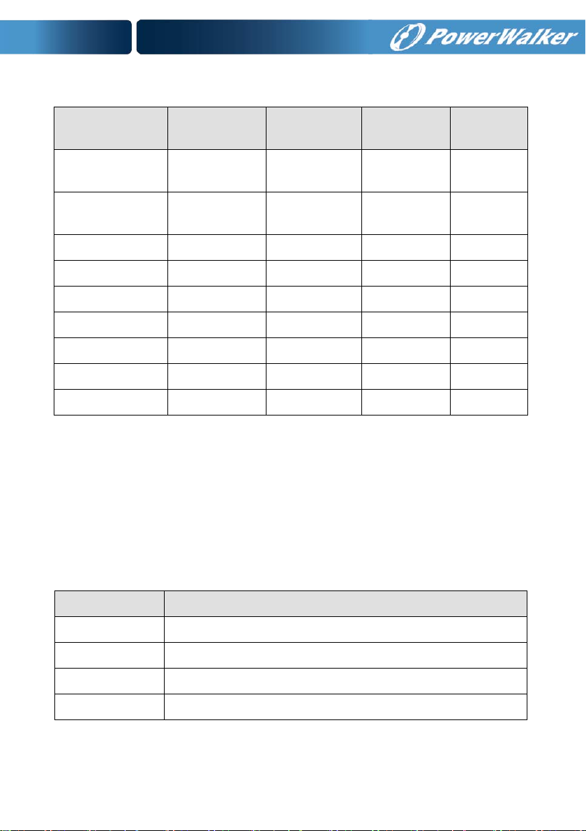
The UPS provides useful information about UPS itself, load status, events,
measurements, identification, and settings through the front panel display.
After powering on, the LCD will display the “WELCOME” logo for several
seconds and then enter to the default page which shows the UPS status
summary. The display automatically returns to the default UPS status
summary screen when no button has been pressed within 15 minutes.
On the UPS status summary screen it provides the following information:
Status summary, including mode and load
Alarm status, if any are present
Notes: alarm including fault and warning information
Battery and charger status, including battery voltage, charger
level and charger status
Running information including parallel UPS and running time
Fig. 5-2 The default LCD display
The more detailed operation of LCD is illustrated in the chapter of 5.4.
26
Page 30
5.2 Operating Mode
The different graphic symbol could be displayed corres ponding to current
operating mode or status.
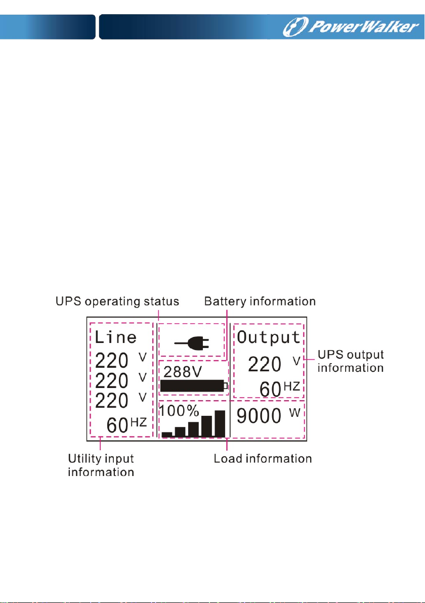
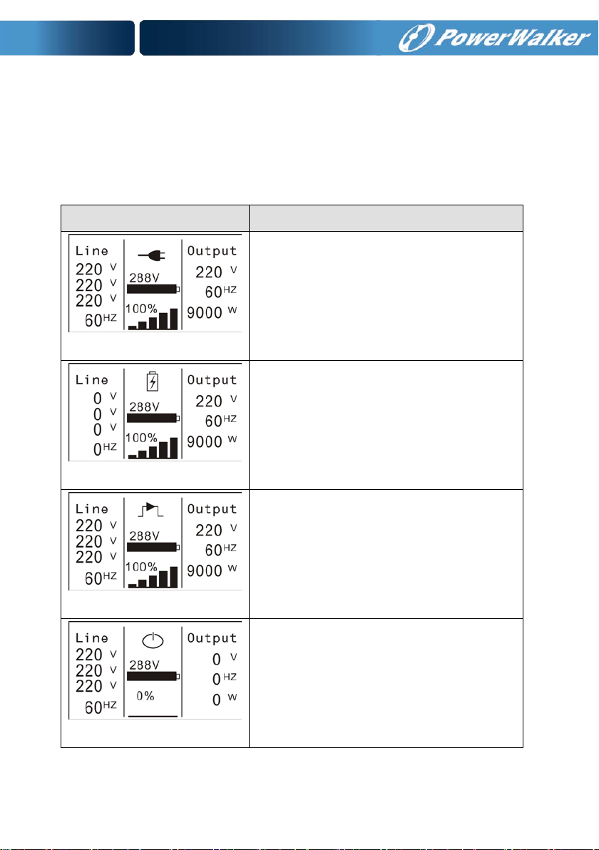
Table 5-4 St atu s Summary Screens
Status Summary Screen
Fig 5-3
Fig 5-4
Fig 5-5
Description
Normal mode:
The UPS is operating in Normal mode from
utility power.
Battery mode:
When the UPS is running in battery mode, the
buzzer beeps once every 4 seconds.
Bypass with output:
The UPS does not have the backup function
when it is in bypass mode. The power used by
the load is supplied from the utility power via
internal filter. The UPS will beep once every 2
minutes in bypass mode.
Fig 5-6
Bypass without output:
The UPS in bypass mode without output
27
Page 31

internal filter while the utility power is in
mode or Battery mode and the load is
the LCD setting or the software
UPS output from HE mode to battery
long for some sensitive load.
the LCD setting or the software
The load should be derated to 60%
single phase input, and there is no
High Efficiency Mode:
After the UPS is turned on, the power used by
the load is sup pli ed fro m th e u tilit y pow er via
normal range, so the high efficiency could be
Fig 5-7
Fig 5-8
gained in the HE mo de. Once the mai ns is loss
or abnormal, the U PS would transfer to Lin e
supplied continuously.
1) The function could be enabled through
(Winpower, etc.).
2) It is attention that the transfer time of
mode is about 10ms. But it is still too
Converter mode
In converter mode, the UPS would free run
with f ixed output frequency ( 50Hz or 60Hz).
Once the mains is loss or abn ormal, the UPS
would transfer to battery mode and the load is
supplied continuously.
1) The function could be enabled through
2)
Warning:
When the warning occurs, it illustrates that
Fig 5-9
there are some abnormal problems during the
operation of UPS. Normally t he problem s are
not fatal and the UPS continues working, but
they should be pai d attention to, o r the UPS
may fail.
(Winpower, etc.).
when running in converter mode with
derating with three phases input.
28
Page 32

fatal problems happened, the UPS would
directly cut off the output or transfer to
LCD would also turn to red.
Fault:
When the fault occurs, it illustrates that some
Fig 5-10
Fig 5-11
Fig 5-12
Fig 5-13
bypass, and keep alarmin g. The backlight of
Overload:
When the UPS is overload, the alarm will beep
twice every sec ond. Som e unnec essary lo ads
should be get r id of one by o ne to decrease
the loads connected to the UPS.
Battery Test
UPS is executing a battery test
Battery fail:
if the battery status detected is “bad battery
detected” or “battery disconnected”, the
symbol of battery failure would be shown and
UPS would alarm.
5.3 Turning On and Turning Off UPS
Attention: Please switch off the connected loads first before turning on
the UPS, and switch on the loads one by one after the UPS is turned on.
Switch off all of the connected loads before turning off the UPS.
29
Page 33

5.3.1 Turning On UPS With Utility
1) Check that power supply connection is correct. Check the breaker
of battery pack is in “ON” position (this step only for long backup
time model).
2) For PowerWalker VFI 10000-20000TP 3/1 set input breaker(M1 &
M2)in “ON” position, for PowerWalker VFI 10000TCP 3/1 model
set input 4P-switch in “ON” position .At this time the fan begins t o
rotate. LCD will show “WELCOME” logo. Then LCD will show the
system status summary screen after UPS finishing self-test.
3) By pressing
buzzer will beep 1s, UPS starts to turn on.
4) A few seconds later, the UPS turns into Line mode. If the utility
power is abnormal, the UPS will transfer to Battery mode without
output interruption of the UPS.
5.3.2 Turning On UPS Without Utility
1) Check the breaker of the battery pack is in “O N” position (this step
only for long backup time model).
2) By pressing
would be powered on. At this time the fan begins to rotate, LCD
will show the “WELCOME” logo. Then LCD will show the default
UPS status summary screen after UPS finishing self-test.
3) By pressing
buzzer will beep 1s, UPS starts to turn on.
4) A few seconds later, the UPS turns into Battery mode. If the utility
power comes back, the UPS will transfer to Line mode without
output interruption of the UPS.
5.3.3 Turning Off UPS With Utility
button continuously for more than 1 second, the
button continuously for mo re than 100ms, t he UPS
button continuously for more than 1 second, the
1) T o turn off the inve rter of UPS by pressin g
for more than 3 seconds and the buz zer will beep 3s. The U PS will
turn into Bypass mode at once.
30
button continuously
Page 34

2) When completing the above action, UPS output voltage is still
present. In order to cut off the UPS output, simply cut off the utilit y
power supply. A few seconds later, LCD display shuts down and n o
output voltage is available from the UPS output terminal.
5.3.4 Turning Off UPS Without Utility
1) To power off the UPS by pressing
than 3 second, and the buzzer w ill beep 3s. The UPS will cut off t he
output at once.
2) A few seconds later, LCD shuts down and no voltage is available
from the UPS output.
button continuously for more
5.4 LCD Operation
Except the default UPS status summary screen, the user could get
more useful information about UPS current status, detailed various
measurements, old events which ever occurred, UPS own
identification, and could change the settings to fit the user own
requirements, optimize the function of UPS.
5.4.1 The Main Menu
In the default UPS status summary screen, when pressing
<1s, the detailed information about alarm, the system status, battery
would be shown.
In the default UPS status summary screen, when pressing
the display would enter main menu tree.
or
>1s,
The main menu tree includes six branches: UPS status menu, event
log menu, measurement menu, control menu, identification menu,
setting menu.
31
Page 35

Fig. 5-14 Main me nu tree
32
Page 36

5.4.2 The UPS Status Menu
By pressing
the next UPS status menu tree.
The content of UPS status menu tree is same as the default UPS status
summary menu .
By pressing
tree.
The detail information about “UPS status”, please see Fig5-14
5.4.3 The Event Log Menu
By pressing on the menu of “Event log”, the display would enter
the next event menu tree.
All the old event, alarm and fault have been recorded here. The
information includes the illustr ation, the event c ode, and the operati ng
time of UPS when the event happened. By press
the event could be displayed one by one.
The max number of record is 30, when the number is larger than 30,
the oldest one would be changed to the newest information.
By pressing
tree.
on the menu of “UPS status”, the display would enter
>1s, the display would return the last main menu
or <1s, all
>1s, the display would return the last main menu
33
Page 37

Fig. 5-15 Event menu tree
5.4.4 The Measurement Menu
By pressing
enter the next measurement menu tree.
A lot of detailed useful information could be checked here, Ex. the
output voltage and frequency, the output current, the load capacity,
the input voltage and frequency, etc.
By pressing
tree.
on the menu of “Measurement”, the display would
>1s, the display would return the last main menu
34
Page 38

Fig. 5-16 Measurement menu tree
5.4.5 The Control Menu
By pressing
next control menu tree.
1) Start B attery Test: is one command to control the UPS to d o the
battery test.
2) Clear EPO status: once EPO status is enabled, the UPS output
would be cut off. To recover to normal status, first EPO connector
should be opened, and enter this menu to clear EPO status, then
UPS would stop alarm and recover to Bypass model. And UPS
needs be turned on by manual operation.
3) Reset Fault status: when fault occurs, UPS would keep in Fault
mode and alarm. To recover to normal status, enter this menu to
reset error status, then UPS would stop alarm and recover to
Bypass mode. And the reason of fault should be checked and
deleted before UPS is turned on again by manual ope r at ion .
on the menu of “Control”, the display would e nter the
35
Page 39

4) Restore factory settings: all the settings would be recover to
default factory settings. It could only be done in Bypass mode.
Fig. 5-17 Cont r ol menu tree
36
Page 40

5.4.6 The Identification Menu
By press
the next identification menu tree.
The identification information includes UPS serial number, f irmware
serial number, model type, would be shown here.
By press
on the menu of “Identification”, the display would ente r
>1s, the display would return the last main menu tree.
Fig. 5-18 Identification menu tree
5.4.7 The Setting Menu
Please contact your local distributor for further information before
using the settings. Some s et tings would ch ange t he s pecification, and
some settings would enable or disable some f unction s. The unsuit able
option set by user may result in potential failures or protecting
37
Page 41

function loss, eve n directly damage the load, battery o r UPS.
The most of settings could only be done while UPS is in Bypass mode .
Fig. 5-19 Setting menu tree
*:Password is USER when enabled
38
Page 42

Output voltage
<
230V
>
...
By press or <1s
The option would flash
Output voltage
<230
V>
By press <
1s
Setting menu tree
Output voltage
<220V>
By press or <1s, to select the wanted option
Output voltage
<220
V>
By press
>1s,
to confirm the setting
The option would stop flashing
after being confirmed
Example: set rated output voltage value
Fig. 5-20 Set rated output voltage value
39
Page 43

6. Special Function
The series UPS has some special functions, which could satisfy some
special application of user. And the functions have own features,
please contact your local distributor for further information before
using the function.
6.1 HE Function
6.1.1 Brief Introduction of HE Function
If HE function is set to enable, after the UPS is turned on, the power
used by the load is directly supplied from the ut ility power via internal
filter while the utility power is in normal range, so the high efficiency
could be gained in HE mode. It is a lso called econo my mode. O nce the
mains is loss or abnormal, the UPS would transfer to Line mode or
Battery mode and the load is supplied continuously.
The great virtue is over all high ef ficiency >0.97 of UPS, to save powe r
for user.
But the disadvantage is 1) the load can not be protected as well as in
Line mode, for the load is directly supplied from the utility; 2) the
transfer time of UP S output from HE mode to Battery mode is about
10ms.
So the function is not suitable t o so me sens itive loads, and the region
where the utility power is unstable.
6.2 Converter Function
6.2.1 Brief introduction of Converter function
In converter mode, the UPS would free run with fixed output
frequency (50Hz or 60Hz). Once the mains is loss or abnormal, the
UPS would transfer to Battery mode and the load is supplied
continuously.
40
Page 44

The great virtue is the output frequency is fixed, which is required by
some very sensitive loads.
But the load should be derated to 60% when running in converter
mode with single phase input, and there is no derating with three
phases input.
6.3 Parallel Function
6.3.1 Brief introduction of the redundancy
N+X is currently the most reliable power supply structure. N
represents the minimum UPS number that the total load needs, X
represents the redundant UPS number, i.e. the fault UPS number that
the system can handle simultaneously. When the X is larger, the
reliability of the powe r syste m i s higher. For occasions where reliabilit y
is highly depended on, N+X is the optimal mode.
As long as the UPS is equipped with parallel cables, up to 4 UPSs can
be connected in parallel to realize output power sharing and power
redundancy.
6.3.2 Parallel installation a nd operati o n
How to install a new parallel UPS system:
1) Before installing a new parallel UPS system, user need to prepare
the input and output wires, the output breaker, and the parallel
cable.
2) Users need to use a standard 25-pin communication cable, whic h
should have 25 cores, corresponding stitches and shield, as the
UPS parallel cable. The length of the paralle l cable is appropriate to
be less than 3m. And there is one standard parallel cable in the
accessor i e s of every UPS.
3) Remove the cover plate of the parallel port on the UPS, connect
each UPS one by one with the parallel cable, and re-screw the
Parallel port cover which is supplied in the accessories.
41
Page 45

4) Strictly follow the chapter of 4, the wiring requirement o f single
UPS to perform the wiring of each UPS.
5) Connect the output wires of each UPS t o an output breaker panel.
6) Disconnect the Jumper on JP1 and JP2 of the terminal block f irst,
and connect each output breaker to a main output breaker and
then to the loads.
7) Each UPS need an independent battery pack.
8) Please refer to the wiring diagram in the following diagram.
9) The distance between th e UPSs in p arallel and the breaker pan el is
required to be less than 20 meters. The difference between the wires
of input and output of the UPSs is required to be less than 20%.
Fig. 6-1 Input and output Terminal Block wiring diagram of
PowerW a lk er VFI 10000-20000TP 3/1
42
Page 46

Fig. 6-2 Input and output Terminal Block wiring diagram of
PowerW a lk er VFI 10000-20000 TP 3/1 model
Fig. 6-3 Parallel Installation Diagram
43
Page 47

10) Do not switch on the output breaker of each UPS, switch on the
input breaker of the each UPS, the UPS should work in bypass with
output, observe their display to check if there are any warning or
fault information, measure the output voltage of each UPS
separately to check if the voltage difference between them is less
than 1V. If the difference is more than 1V, check the wiring.
11) Press the
all the UPSs would transfe r to the INV mode togethe r. Measure the
output voltage of each UPS separately to check if the voltage
difference between them is less than 0.5V. If the difference is more
than 1V, the UPSs need to be regulated.
12) Press the
and transfer to the Bypass mode, switch on the output breaker of
each UPS to parallel all the output of UPSs together.
13) Press the
after turning on, the UPSs should work parallel in the Line mode.
How to join a new UPS to a parallel system:
1) First the parallel system must be installed one main maintenance
mechanical switch or static switch.
2) Regulate the output voltage of the new UPS separately: check if
the output voltage difference between the new UPS and the
parallel system is less than 0.5V.
3) Ensure the bypass of the parallel system is normal and the bypass
setting is “enable”, remove the cover plate of maintenance switch
on the rear panel of each UPS, the UPS system would transfer to
bypass automatically, For P owerW alker VFI 1000 0-20000TP 3/1,set
the own maintenance switch of each UPS from “UPS” to “BPS”. For
PowerWalker VFI 10000TCP 3/1 model, turn the maintenance
switch in the “ ON” position, and tu rn the output switch in the “ OFF”
position.
button of one UPS , e a ch UPS w ou l d sta rt to t urn on ,
button of one UPS, each UPS would start to turn off
button of one UPS , e a ch UPS w ou l d sta rt to t urn on ,
44
Page 48

4) For PowerWalker VFI 10000-20000TP 3/1,Set the main
maintenance switch or static switch from “UPS” to “BPS”, For
PowerWalker VFI 10000TCP 3/1 model, turn the maintenance
switch in the “ ON” position, and tu rn the output switch in the “ OFF”
position, switch off the main output breaker and the main input
breaker, the UPSs would shut down.
5) Ensure the UPSs shut down totally, add the new UPS and reinstall
the new UPS parallel system by following step 1) to 9) of last
chapter - “install a new parallel UPS system”.
6) For PowerWalker VFI 10000-20000TP 3/1, Switch on the main
input breaker and the main output breaker, and set the main
maintenance switch or static switc h from “BPS” to “UPS”, then set
the UPS own maintenance switch from “BPS” to “ UPS” and screw
the maintenance cover plate back again. Press the
one UPS, each UPS would start to turn on, after turning on, the
UPSs should work parallel in the Line mode.
For PowerWalker VFI 10000TCP 3/1 model, t urn the maintenance
switch in the “ OFF” position, and tu rn the output switch in the “ON”
position, then turn the UPS own maintenance switch in the “OFF”
position, and turn the UPS own output switch in the “ON” position,
then screw the m aintenance cover p late back again. Pres s the
button of one UPS, each UPS would start to turn on, after turning
on, the UPSs should work parallel in the Line mode.
butto n of
How to remove a single UPS from a parallel system:
1) First the parallel system must be installed one main maintenance
mechanical switch or static switch.
2) Ensure the bypass is normal and the bypass setting is “enable”,
remove the cover plate of maintenance switch on the rear panel of
each UPS, the UPS system would transfer to bypass automatically,
For PowerWalker VFI 10000-20000TP 3/1,set the own
45
Page 49

maintenance switch of each UPS from “UPS” to “BPS”. For
PowerW a lk er VFI 10000TCP 3/1 model, t urn the own maintenance
switch in the “ON” position, and turn the own output switch in the
“OFF” position.
3) For PowerWalker VFI 10000-20000TP 3/1, Set the main
maintenance switch or static switch f rom “UPS” to “B PS”, switch off
the main output breaker and the main input brea ker, and the UPSs
would shut down.
For PowerWalker VFI 10000TCP 3/1 model, turn the own
maintenance switch in the “ON” position, switch off the main
output switch and the main input switch, and the UPSs would shut
down.
4) Ensure the UPSs shut down totally, remove the wan ted UPS and
reinstall the new UPS parallel system by following step 1) to 9) of
last chapter - “install a new parallel UPS system”.
5) If the removed UPS or the remained UPS will be used in a
stand-alone mode, then JP1 and JP2 on the terminal block should
be connected with a short connection wire.
6) Switch on the main input breaker/switch and the main output
breaker/switch, For PowerWalker VFI 10000 -20000TP 3/1 ,set the
main maintenance switch or static switch f rom “BPS” to “ UPS”, then
set the UPS own maintenance switch from “BPS” to “UPS” and
screw the maintenance cover plate back again. For PowerWalker
VFI 10000TCP 3/1 model, turn the maintenance switch in the
“OFF” position, then turn the own maintenance switch in the “OFF”
position and screw the maintenance cover plate back again, t hen
Press the
after turning on, the UPSs should work parallel in the Line mode.
button of one UPS, each UPS would start to turn on,
46
Page 50

6.4 PowerWalker VFI 10000TP 3/1 Optional Design of
Charger Current
6.4.1 Our charger output current has two optional levels
(2A&4A) for different battery pile.
6.4.2 Operate method:
2A charger current method
Insert short circuit pin 104-10000-01 in the C N7 positi on of charger
board. This is charging for 7AH*24 pcs or 9AH*24 pcs.
4A charger current method
Pull out short circuit pin 104-10000-01 from CN7 position of charger
board. This is for 2 piles of 7AH*24 pcs or 2 piles of 9AH*24 pcs.
Short circuit pin 104-10000-01
47
Page 51

6.5 Backfeed Protection
To support protection against UPS backfeeding a new logic is integrated
into PowerWalker VFI 10000-20000TP 3/1 model. But in PowerWalker
VFI 10000TCP 3/1 model,there’s no this function.
Using backfeed protection
On customers side an additional external isolation device (magnetic
contactor, MC or minimum voltage tripping device) must be provided as
shown in F ig. 6-3. The isolation device must be able to carry the UPS
input current (see resp. table of basic UPS operating instructions ).
The isolation device has to be installed in the bypass source path.
Cabling of the backfeed terminals contains a jumper and two cables to
the optional external isolation device.
48
Page 52

PSDR board
Coil
MC/coil.out
MC/coil.in
Mains 2:
L/N
F
(2A)
slow
blow
Terminals
Output/L
Output/N
Relay
Normally closed
Backfeed
No active
Optional Magnctic
Contactor(MC)
UPS
Mains T.B
Backfeed T.B
MC/coil.out
MC/coil.in
Fig. 6-4 Power Walker VFI 10000-20000 TP 3/1 and external isolation
device(in this example a magnetic contactor (MC))
Fig. 6-5 Backfeed terminal
49
Page 53

Operation
If bypass thyristor is short (short circuit) and UPS runs in double
conversion mode (online) the following steps follow:
The backfeed relay opens and the message “backfeeder” is shown on the
LCD panel
Reset
T o reset the backfeed logic the UPS device must be switched Off for some
seconds
50
Page 54

Alarm code:71
Alarm code:72
on.
Alarm code:84
Alarm code:15
Alarm code:14
Alarm code:92
7. Trouble Shooting
If the UPS system does not operate correctly, first check the operating
information on the LCD display.
Please attempt to s olve the problem using the ta ble below . If the proble m
still persists, consult your dealer.
7.1 Trouble Shooting According To Warning Indication
Problem Displayed Possible cause Remedy
Epo Active
On Maintain Bypass
Battery Disconnect
Alarm code:11
Battery low
Alarm code:12
Output Overload
Alarm code:41
Fan Failure
Charger Fail
Over Charge
Model Pin Error
EPO connector is closed Check the EPO connector status
Maintain bypass switch
is open
Battery pack is not
connected correctly
Battery voltage is low When audible alarm sounding
Overload Check the loads and remove some
Fan abnormal Check if the fan is running
The charge fails Consult dealer.
Battery is over charged The UPS will turn off the charger
UPS internal fault Consult dealer.
Check the maintain bypass switch
status
Do the battery test to confirm.
Check the battery bank is
connected to the UPS.
Check the battery breaker is turn
every second, battery is almost
empty.
non-critical loads.
Check if some loads are failed.
normally.
until the battery voltage is normal
51
Page 55

Alarm code:86
Alarm code:E3
Alarm code:E4
disconnected
has no this case)
same input source.
are forbidden to parallel.
are forbidden to parallel.
Alarm code:EB
Heatsink Over
Temperature
Inside temperature of
UPS is too high
Check the ventilation of UPS and
the ambient temperature.
Para Cable Male Loss
Para Cable Fema le Loss
Para Bat Differ
Alarm code:E6
Para Byp Differ
Alarm code:E8
(PowerWalker VFI
10000TCP 3/1 mode
Para Line Differ
Alarm code:E7
Para Work Mode Differ
Alarm code:E9
Para Rate Power Differ
Alarm code:EA
The parallel cable is
disconnected
The parallel cable is
disconnected
The battery packs of
some UPSs are
The M2 bypass input of
some UPSs is
disconnected
The M1 line input of
some UPSs is
disconnected
There are different
power strategy setting
in parallel system
There are different UPSs
in parallel system
Check the parallel cable.
Check the parallel cable.
Check if all the battery pack is
connected.
Check the building wiring and
input cable.
Check if the M2 breaker is closed.
Ensure the UPSs are connected to
same input source.
Check the building wiring and
input cable.
Check if the M1 breaker is closed.
Ensure the UPSs are connected to
The UPSs with different power
strategy setting (Ex. one Line
mode and one Converter mode)
The UPSs with different capacity
(Ex. one 10KVA and one 20KVA)
ECO In Para
HE function is enabled
in parallel system
52
HE function is forbidden in parallel
system.
Page 56

Check if some loads are failed.
Check if some loads are failed.
turning on again.
center.
Alarm code:21
Alarm code:22
Alarm code:23
Alarm code:24
Alarm code:25
Alarm code:32
7.2 Trouble Shooting According To Fault Indication
Problem Displayed Possible cause Remedy
Inv Overload Fault
Alarm code:42
Byp Overload Fault
Alarm code:43
Output Short Circuit
Alarm code:31
Heatsink Over
Temperature Fault
Alarm code:81
Bus Over Voltage
Overload
Overload
Output short
circuit
Inside
temperature of
UPS is too high
UPS internal fault Consult dealer.
Check the loads and remove some
non-critical loads.
Check the loads and remove some
non-critical loads.
Remove all the loads. Turn off the UPS.
Check if UPS output and loads is short
circuit.
Ensure short circuit is removed before
Make sure the UPS is not overloaded; the
air vents are not blocked and the
ambient temperature is not too high.
Wait for 10 minutes for the UPS to cool
down before turning on again. If failed,
please contact the distributor or service
Bus Under Voltage
Bus Unbalance
Bus short
Bus Softstart Fail
Inv Over Voltage
UPS internal fault Consult dealer.
UPS internal fault Consult dealer.
UPS internal fault Consult dealer.
UPS internal fault Consult dealer.
UPS internal fault Consult dealer.
53
Page 57

Alarm code:33
Alarm code:34
capacitive
there is no overload, then turn on UPS.
Alarm code:E2
utility power. Please Consult dealer.
Inv Under Voltage
UPS internal fault Consult dealer.
Inv Softstart Fail
Negative Power Fault
Alarm code:E1
Cable male and female
Loss fault
Backfeeder
Alarm code:93
UPS internal fault Consult dealer.
The load is pu r e
inductive and
The parallel cable
is disconnected
UPS internal fault
Remove some non-critical loads.
Bypass supplies the load first, ensure
Check the parallel cable.
Don’t touch any terminal of the
equipments which connect one utility
power with the UPS even you cut off the
7.3 Trouble Shooting In Else Cases
Problem Possible cause Remedy
No indication, no
warning tone even
though system is
connected to mains
No input voltage Check the building wiring and input
cable.
Check if the input breaker is closed.
power supply
BYPASS LED light up
even though the power
supply is available
BATTERY LED lights up,
and audible alarm
sounding every 1 beep
in every 4 seconds
Inverter not switched
on
Input voltage and/or
frequency are out of
tolerance
Press On-Switch “I” to turn on UPS.
Check input power source.
Check the building wiring and input
cable.
Check if the input breaker is closed.
54
Page 58

Emergency supply
period shorter than
nominal value
Please have the following information at hand before calling the
After-Sales Service Department:
1. Model number, serial number
2. Date on which the problem occurred
3. LCD/LED display information, Buzzer alarm status
4. Utility power condition, load type and capacity, environment
temperature, ventilation condition
5. The information (battery capacity, quantity) of external battery
pack if the UPS is “S” model
6. Other information for complete description of the problem
Batteries not fully
charged / batteries
defect
Charge the batteries for at least 12
hours and then check capacity.
55
Page 59

8. Battery Maintenance, Replacement and
Disposal
8.1 Maintenance
■ This series UPS only requires minimal maintenance. The battery
used for standard models are value regulated sealed lead-acid
maintenance free battery. These models require minimal repairs.
The only requirement is to charge the UPS regularly in order to
maximize the expected life of the battery. When being connected
to the utility power, whether the UPS is turned on or not, the UPS
keeps charging the batteries and also offers the protective
function of overcharging and over-discharging.
■
The UPS should be ch arged once eve ry 4 t o 6 months if it has n ot
been used for a long time.
■
In the regions of hot climates, the battery should be charged and
discharged every 2 months. The standard charging time should
be at leas t 12 hours.
■
Under normal conditions, the battery life lasts 3 to 5 years. In
case if the battery is found not in good condition, earlier
replacement should be made. Battery replacement should be
performed by qualified personnel.
■
Replace batteries with the same number and same type of
batteries.
■
Do not replace the ba ttery individually. All the batteries should be
replaced at the same time following the instructions of the battery
supplier.
■
Normally, the batteries should be charged and discharged once
every 4 to 6 months. Charging should begin after the UPS shuts
down automatically in the course of discharging, the standard
charging time for the standard UPS should be at least 12 hours.
56
Page 60

8.2 Replacement and Disposal of Batteries
1) Before disposing of batteries , remov e condu cti ve jewe lry su ch as
necklace, wrist watches and rings.
2) If it is necessary to replace any connection cables, please
purchase the original materials from the authorized distributors or
service cen ters, so as to avoid overheat or spar k resulting in fire
due to insufficient capacity.
3) Do not dispose of batteries or battery packs in a fire, they may
explode.
4) Do not open or mutilate batteries, released electrolyte is highly
poisonous and harmful to the skin and eyes.
5) Do not short the positive and negative of the battery electrode,
otherwise, it may result in electric shock or fire.
6) Make sure that there is no voltage before touching the batteries.
The battery circuit is not isolated from the input potential circuit.
There may be hazardous voltage between the battery terminals
and the ground.
7) Even though the input breaker is disconnected, the components
inside the UPS are still co nnected wit h the bat teries, a nd there a re
potential hazardous voltages. Therefore, before any maintenance
and repairs work is carried out, switch off the breaker of the
battery pack or disconnect the jumper wire of connecting between
the batteries.
8) Batteries contain hazardous voltage and current. Battery
maintenance such as the battery replacement must be carried out
by qualified personnel who are knowledgeable about batteries. No
other persons should handle the batteries.
Easy for Battery Replacement (for PowerW alk er VFI 10000-20000 TP
3/1model)
57
Page 61

Open the front panel and request service engineer to replace
batteries. Steps:
1) Remove the fr ont panel a nd disconne ct the connector on the LCD
display boa rd. See Fig. 8-1.
Fig. 8-1 Easy for Battery Replacement -Step 1
2) Disconnect the battery pack DC connectors and remove the
battery fixed plate. See Fig. 8-2.
battery fixed plate
Fig. 8-2 Easy for Battery Replacement -Step 2
58
Page 62

3) Remove the battery pack from the cabinet. See Fig. 8-3.
Fig. 8-3 Easy for Battery Replacement -Step 3
4) Replace t he old battery packs with the new ones.
5) Reconnect the DC cables.
Note: The battery pack is 20kg weight, be careful not to fall off when
you operate the battery replacement.
If you want to replace batteries without powering down the UPS, you
need to set the UPS work in Bypass Mode. That is to remove the
maintenance switch cover plate of UPS an d set t he mainte nance swit ch
from “UPS” to “BPS”, turn the M1/M2/N input breaker in the “OFF”
position(you need open the N breaker’s cover at first), and then you can
repla ce it.
59
Page 63

Pin #
Description
I/O
2
TXD
Output
3
RXD
Input
5
GND
Input
9. Communication Port
9.1 RS232&USB Interface
RS232&USB interface is for the monitoring software and firmware
update. There is only one option can work in the same time and same
product.
1) The following is the pin assignment and description of DB-9
connector.
2) The USB port is compliance with USB 1.1 protocol for its
communication software.
9.2 Intelligent Slot
This series is equipped with two intelligent slot for Webpower
(optional accessory) or other optional card to achieve remote
management of the UPS through internet / intranet. Please contact
your local distributor for further information.
9.3 AS400 Interface (Option)
Except for the communication protocol as mentioned above, this series
UPS has AS400 card (an optional accessory) for AS400 communication
protocol. Please contact your local distributor for details. The following
is the pin assignment and description of DB -9 conne ctor in AS400 car d.
60
Page 64

1
UPS Fail
Output
6
Bypass
Output
2
Summary Alarm
Output
7
Battery Low
Output
3
GND
Input 8 UPS ON
Output
9
Line Loss
Output 5 Common
Input
Pin # Description I/O Pin # Description I/O
4 Remote Shutdown Input
Fig. 9-1 signal of AS400 interface
61
Page 65

10. Software Installation
WinPower is UPS monitoring software, featuring user-friendly interface to
monitor and control your UPS. This unique software provides complete
power protection for computer system while power failure. With the
software us ers can moni to r an y UP S st at us on th e sa me LAN. Furthermore,
a UPS can provide security protection for more than one computer o n the
sam e LAN at the same time, such as shutting down system in security,
saving application data and shutting down the UPS when power fails.
Software Installation on your PC:
Connected by USB to a PC or notebook, the Software enables
communication between the UPS and the computer. The UPS software
monitors the status of the UPS, shuts down the system before the UPS is
exhausted and can remotely observe the UPS via the Network (enabling
users to manage their system more effectively). Upon AC failure or UPS
battery low, UPS takes all necessary actions without intervention from the
system administrator. In addition to automatic file saving and system
shut-down functions, it can also send warning messages via pager, e-mail
etc.
• Use the bundled CD and follow the on-screen instructions t o install
the software WinPower.
• Enter the following serial No. to install software:
511C1-01220-0100-478DF2A
• After the software is successfully inst alled, the communicatio n with
UPS has been established and an green icon will appear in the
system tray.
• Double-click the icon to use the monitor software (as above).
62
Page 66

• You can schedule UPS shutdown/start-up and monit or UP S statu s
through PC.
• Detail instructions please refer to the e-manual in the software.
Check www.powerwalker.com/winpower.html from time to time to get the latest
version of monitoring software.
63
Page 67

Page 68

Online USV
PowerWalker VFI 10000TCP 3/1
PowerWalker VFI 10000TP 3/1
PowerWalker VFI 20000TP 3/1
Bedienungsanleitung (DE)
Unterbrechungsfreies Stromversorgungssystem
Page 69

Inhaltsverzeichnis:
1. Sicherheit ..................................................................................................... 1
1.1 Installation............................................................................................... 1
1.2 Betrieb .................................................................................................... 2
1.3 Wartung, Instandhaltung und Störungen ................................................ 3
1.4 Transport ................................................................................................ 4
1.5 Lagerung ................................................................................................ 4
1.6 Standards ............................................................................................... 5
2. Beschreibung der verwendeten Symbole ................................................ 6
3. Einführung ................................................................................................... 7
3.1 System- und Modellbeschreibung .......................................................... 7
3.2 Produkt- und Leistungsbeschreibung ................................................... 11
4. Installation ................................................................................................. 13
4.1 Auspacken und Überprüfen .................................................................. 13
4.2 EIN- UND AUSGANGSNETZKABEL UND SCHUTZERDUNG ........................ 16
4.3 Bedienungshinweise für den Anschluss einer externen Batterie ......... 21
5. Bedienung ................................................................................................. 23
5.1 Anzeige-Display .................................................................................... 23
5.2 Betriebsmodus ...................................................................................... 27
5.3 USV Ein- und Ausschalten ................................................................... 30
5.4 LCD-Bedienung .................................................................................... 32
6. Spezialfunktion ......................................................................................... 41
6.1 HE-Funktion .......................................................................................... 41
6.2 Konverterfunktion ................................................................................. 42
Page 70

6.3 Parallel-Funktion ................................................................................... 42
6.4 PowerWalker VFI 10000TCP 3/1 Optionales Design des Ladegeräts . 48
6.5 Nachspeiseschutz ................................................................................ 49
7. Fehlerbehebung ........................................................................................ 52
7.1 Fehlerbehebung gemäß der Warnanzeige ........................................... 52
7.2 Fehlerbehebung gemäß der Fehleranzeige ......................................... 54
7.3 Sonstige Fehlerbehebung .................................................................... 56
8. Batteriewartung, Austausch und Entsorgung ....................................... 57
8.1 Wartung ................................................................................................ 58
8.2 Austausch und Entsorgung der Batterien ............................................. 59
9. Kommunikationsport ................................................................................ 62
9.1 RS232&USB Schnittstelle .................................................................... 62
9.2 Intelligent Slot ....................................................................................... 62
9.3 AS400 Schnittstelle (Option)................................................................. 62
10. Software Installation ..................................... Error! Bookmark not defined.
Page 71

1. Sicherheit
Bitte lesen Sie die folgenden Sicherheitshinweise und die
Bedienungsanleitung vor der Installation und Erstbenutzung
aufmerksam durch!
1.1 Installation
★ Wenn das USV-System aus einer kalten Umgebung in den
Betriebsraum gebracht wird, kann eine Kondensation auftreten.
Das USV-System muss vor der Inbetriebnahme absolut trocken
sein. Betreiben Sie das Gerät erst nach einer
Akklimatisierungszeit von mindestens 2 Std.
★ Betreiben Sie das Gerät nicht in der Nähe von Wasser oder in
einer feuchten Umgebung.
★ Stellen Sie das US V -System nicht in der Nähe v on W ärmequellen
auf oder setzen Sie es nicht direkter Sonneneinstrahlung aus.
★ Halten Sie die Ventilationsöffnungen des USV-Gehäuses frei.
★ Schließen Sie keine Geräte an die Ausgang-Buchse oder
Klemmen an, die Die USV überlasten (z.B. Laserdrucker etc.).
★ Platzieren Sie das Kabel so, dass niemand darauf treten oder
darüber stolpern kann.
★ Die USV ist mit Erdungsklemmen im Endkonfigurationssystem
ausgestattet, mit Potenzialausgleich zur externen
USV-Batteriebox.
★ Eine integrierte Notvorrichtung welche verhindert, dass die
Page 72

Spannung zu hoch wird, sollte vorgesehen sein.
★ Für den Kurzschlussschutz sind bauseits Sicherungen und
Lasttrennschalter erforderlich.
★ Für den Anschluss von Drei-Phasen-Geräten an ein IT-Netz,
sollte eine vierpolige Vorrichtung in der Gehäuseverdrahtung
vorgesehen sein, die alle Phasenleiter und Neutralleiter trennt.
★ Dies sind permanent angeschlossene Vorrichtungen, die nur von
qualifiziertem Fachpersonal installiert werden sollten.
★ Vor dem Anschluss des Gerätes an die Stromversorgung, zuerst
die Erdung anschließen.
1.2 Bedienung
★ Das Erdungskabel während des Betriebs nicht von der
USV-Anlage abziehen, da sonst die Schutzerdung der
USV-Anlage und aller angeschlossenen Verbraucher aufgehoben
wird.
★ Die Ausgangsklemmen können stromführend sein, auch wenn
die USV nicht an die Steckdose bzw. an die Einspeisung der
Hausinstallation angeschlossen ist.
★ Um die USV völlig abzuschalten, stellen Sie die
Eingangsschutzschalter M1/M2/N in die “OFF” Position (für
PowerWalker VFI 10000-20000 TP 3/1), die
Eingangsschutzschalter R/S/T/N i n die “OFF” Position stellen (für
PowerWalker VFI 10000TCP 3/1), dann das Netzkabel ziehen.
Page 73

★ Stellen Sie sicher, dass keine Flüssigkeit oder sonstige
Fremdkörper in die USV gelangen.
1.3 Wartung, Instandhaltung und Störungen
★ Das USV-System arbeitet mit gefährlichen Spannungen.
Reparaturen sind grundsätzlich nur von qualifiziertem und
geschultem Wartungspe rs onal du r chzuf ühren.
★ Achtung - Gefahr eines elektrischen Schlags. Selbst nach
Trennung vom Stromversorgungsnetz (Gebäudeverkabelung)
bleiben Bauteile innerhalb der USV an die Batterien
angeschlossen und befinden sich unter gefährlichem
Spannungspotential.
★ Trennen Sie vor jeder Dienstleistung und/oder Wartung die
Batterien. Stellen Sie sicher, dass kein Strom und keine
gefährliche Spannung im Kondensator oder BUS-Kondensator
vorhanden sind.
★ Batteri en dürfen nur von qualifiziertem Personal ersetzt werden.
★ Achtung - Gefahr eines elektrischen Schlags. Der
Batteriestromkreis ist nicht von der Eingangsspannung isoliert.
Zwischen den Batterieanschlüssen und der Erdung können
gefährliche Spannungen auftreten. Stellen Sie vor der Wartung
sicher, dass keine Spannung vorhanden ist!
★ Batterien können Stromschlag verursachen und weisen hohen
Kurzschluss Strom auf. Ergreifen Sie alle unten auf ge führten un d
alle notwendigen Vorsichtsmaßnahmen, wenn Sie mit den
Page 74

Batterien arbeiten:
- entfernen Sie alle Uhren, Ringe und andere metallischen
Objekte.
- verwenden Sie nur Werkzeuge mit isolierten Griffen.
★ Beim Austauschen der Batterien dieselbe Anzahl und denselben
Batterietyp verwenden.
★ Versuchen Sie nicht, Batterien durch Verbrennen zu vernichten.
Dies könnte eine Explosion der Batterie verursachen.
★ Batterien nicht öffnen oder zerstören. Elektrolyt kann Haut und
Augen reizen. Es kann giftig sein.
★ Ersetzen Sie die defekte Sicherung durch eine neue mit der
gleichen Amperezahl, um eine Brandgefahr zu vermeiden.
★ Das USV-System nicht demontieren, mit Ausnahme des
qualifizierten Wartungspersonals.
1.4 Transport
★ Bitte transportieren Sie das USV-System nur in der
Originalverpackung (um es vor Schlägen und Stößen zu
schützen).
1.5 Lagerung
★ Die USV muss in einem trockenen und gut belüfteten Raum
aufbewahrt werden.
Page 75

* Sicherheit
IEC/EN 62040-1
*EMS
ESD........................................:IEC/EN 61000-4-2
Level 3
RS..........................................:IEC/EN 61000-4-3
Level 3
EFT.........................................:IEC/EN 61000-4-4
Level 4
Überspannung..........................:IEC/EN 61000-4-5
Level 4
Niederfrequenz Signale.............:IEC/EN 61000-2-2
1.6 Standards
* EMI
Leitungsgeführte Emissionen.........:IEC/EN 62040-2
Emittierte Strahlung…...................:IEC/EN 62040-2
Warnung: Dieses Produkt ist zur industriellen und kommerziellen
Nutzung in der zweiten Umwelt-I nst all ationsbeschränkung oder es
können zusätzliche Maßnahmen erforderlich sein.
Kategorie C3
Kategorie C3
Page 76

2. Beschreibung der verwendeten Symbol e
Einige oder alle der folgenden Symbole können in dieser
Bedienungsanleitung verwendet werden. Es ist ratsam, sich mit ihnen
vertraut zu machen und ihre Bedeutung zu verstehen:
Page 77

3. Einführung
3.1 System- und Modellbeschreibung
Diese On-Line-Serie ist eine unterbrechungsfreie Stromversorgung mit
eingebauter Doppelwandler-T echnologie. Sie bietet perfekten Schutz für
Computerausrüstung, Rec hnergesteuertes Kommunikationssystem.
Das Doppelwandler-Prinzip eliminiert alle Netzstörungen. Ein
Gleichrichter konvertiert den Wechselstrom aus der Steckdose in
Gleichstrom. Dieser Gleichstrom versorgt den Wechselrichter. A uf B as is
dieser DC-Spannung erzeugt der Inverter eine sinusförmige
AC-Spannung, die die Last dauerhaft versorgt.
Computer und Peri pheriegeräte werden somit vollständig durch die USV
versorgt. Im Falle eines Stromausfalls wird der Inverter von
wartungsfreien Batterien betrieben.
Diese Bedienungsanleitung deckt die PowerWalk er VFI 10000-20000 T P
3/1 Modelle und das PowerWalker VFI 10000TCP 3/ 1 Modell ab.
Herausragende Leistungsmerkmale der Tower-3-Phasen-USV-Serie
sind:
Online-USV mit reiner Sinusausgangsspannung.
Page 78

Echte Online-Doppelwandler-Technologie mit hoher
Leistungsdichte, Unabhängigkeit der Netzfre quenz und
Generator-Kompatibilität.
Insgesamt hoher Wirkungsgrad > 93%, Betriebskosteneinsparung.
Echte Drei-Phasen-Leistungsfaktorkorrektur und h oher
Eingangsleistungsfaktor (PF>0.99). Sparen Sie Installationskosten
und Rückspeisungsschutz für das vorgeschaltete Netz.
Hoher Aus ga ngsleistungsfaktor (0,9), um die Las tart anzupassen.
Intelligente Batterie-Management-Technol ogie, die ein erweitertes
Batterie-Management verwendet, um die Batterielebensdauer zu
erhöhen und die Ladezeit zu optimieren.
Wählbarer Hocheffizienz-Modus (ECO -Modus) oder CVCF
Betriebsmodus.
Combo-Eingang (einphasig oder dreiphasig) automatische
Erkennung
Schutz gegen Spannungsrückspeisung
Start-on Batterie-Leistungsfähigkeit, um die USV auch ohne
Netzstrom zu starten.
Standard Kommunikationsmöglichkeiten: eine
RS-232-Schnittstelle, ein USB-Kommunikationsanschluss.
Optionale Karten-Konnektivität mit erweiterten
Kommunikationsmöglichkeiten
Fernabschaltungskontrolle über den Remote-Power-off (RPO)
Port.
Für Tower Power Walk e r V FI 10000-20000 TP 3/1, Wartungen
werden vereinfacht d urch den si cheren Austausch der A kkus o hne
Abschalten der USV. Aber das Power Walke r VFI 10000TCP 3/1
Modell hat diese Funktion nicht.
Page 79

Die N + X Parallelredundanz erhöht die Zuverlässigkeit und
Flexibilität. Die max. Parallelanzahl ist 4.
Benutzerfreundliches LCD-Display und LED-Anzeigen.
Für Tower Power Walker V FI 1000 0-20000 TP 3/1, einfacher
Batteriewechsel oder Erweiterung, zur Verlängerung der
Backup-Zeit. Aber das Power W al ker VFI 10000T C P 3/1 Modell hat
diese Funktion nicht.
Die Ansicht der Tower 3-Phasen-Serie:
Siehe Bild 3-1
Power Walker VFI 10000 TP 3/1 Rückansicht
Page 80

Parallel Port
(Optional)
Intelligent Slot
EPO、、RS232 USB
Fan
AS400
Input Breaker
Terminal Blocks
Cover
External Battery
IEC Connector
Maintenance and Output
Switch Cover
Power Walker VFI 20000 TP 3/1 Rückansicht
Power Walker VFI 10000TCP 3/1 Rückansicht
Abb. 3-1 Rückansicht des USV 3-Phasen-Serie
Page 81

10000TP 3/1
20000TP 3/1
10000TCP 3/1
Nennleistung
10KVA/9KW
20KVA/18KW
10KVA/9KW
Frequenz (Hz)
50/60
ng
Strom
L1/L2/L3:23A MAX
L1/L2/L3:46A MAX
L1/L2/L3:23A MAX
ng
Strom
43A MAX
86A MAX
51.8A MAX
ng
3.5A/41.7A
7.0A/83.3A
3.5A/41.7A
(WxDxH) mm
(kg)
Modell
Spannung
Frequenz
Leistungsfaktor
PowerWalker VFI
PowerWalker VFI
PowerWalker VFI
10000TCP 3/1
3.2 Produkt- und Leistungsbeschreibung
1) Allgemeine Spezifikation
Modell
Spannu
Eingang
Spannu
Batterie
Spannu
Ausgan
g
Strom
Abmessung
Nettogewicht
PowerWalker VFI
(110-276) VAC (abhängi g von der Last)
200VAC/208VAC/220VAC/230VAC/ 240VAC*
45A/48.1A/45.5A/4
127 188 85
2) Elektrische Leistung
PowerWalker VFI
288VDC 240VDC
90A/96.2A/90.9A/8
350x650x890 260*550*708
PowerWalker VFI
45A/48.1A/45.5A/4
10000TP 3/1
20000TP 3/1
Eingang
dreiphasig 50/60 Hz±10% >0.99(@Volllast)
Page 82

Ausgang
Leistun
r
Lastverlagerung zum
Lastverlagerung zum
Lastverlagerung zum
Lastverlagerung zum
*: Wird die Ausgangsspannung auf 200V eingestellt, wird die
Ausgangsspannung auf 90% herabgestuft.
Spannungs
regelung
±1%
3) Betriebsumgebung
Temperatur Feuchtigkeit Höhe Lagertemperatur
gsfakto
0.9 lag
Frequenztoler
anz.
Synchronisiert
50/60Hz±10%
im Line-Modus
(AC-Modus)
±0.1% der
normalen
Frequenz im
Batteriebetrie
b
Verzerrung Überlastfähigkeit
100%-110%
Bypass-Modus nach
5 Minuten
THD <2%
Volllast
(Lineare
Last) /
<5% als
Bezug für
nichtlineare
Last
110%-130%
Bypass-Modus nach
1 Minute
130%-150%
Bypass-Modus
nach10 Sekunden
>150%
Bypass-Modus nach
2 Sekunden
Stromver
hältnis
3:1
0°C-45°C <95% <1000m -15°C-50°C
Hinweis: wenn die USV installiert oder an e inem O rt über 1000m Höhe
eingesetzt wird, muss die Ausgangsleistung wie folgt reduziert werden:
Höhe (M) 1000 1500 2000 2500 3000 3500 4000 4500 5000
Maximalleistung
100% 95% 91% 86% 82% 78% 74% 70% 67%
Page 83

4. Installation
Die Installation darf nur von qua lifiziertem Elektro-F achpersonal in
Einklang mit den geltenden Sicherheitsbest i mmungen erfolgen!
4.1 Auspacken und Überprüfen
1. Verbringen an den Aufstellort
Die Tower 3-Phasen-USV Serie hat Räder und gestattet nach dem
Auspacken einen einfachen Transport an den Aufstellort. Ist der
Aufstellort jedoch weit vom Standort der Anlage entfernt empfehlen wir,
die USV vor dem Auspack en, mit eine m Hubwagen , an den A ufstellort z u
transportieren.
2. Auspacken und Überprüfen
1) Am Aufstellort ist beim Aus pac k en ä ußerste Vorsicht geboten, um das
Gerät nicht zu beschädigen. Prüfen Sie das gesamte
Verpackungsm aterial, um sicherzus tellen, dass kei ne Teile fehlen. Das
Paket enthält:
● Eine USV
● Eine Bedienungsanleitung
● En Kommunikationskabe l
● Abdeckung für Paralle lsc hnittstelle
Page 84

Werkzeug
Schritt2
Entfernen Sie die Ve rpackung nach der Abfol ge von Abb. 4-1 bis A bb. 4-4.
(nur für PowerWalker VFI 10000-2000 0 TP 3/1 )
Hubwagen
Kreuzschlitzschraubendreher
Schere
Schraubenschlüssel
Abb. 4-1 Auspacken Schritt1
Abb. 4-2 Auspacken
Page 85

Abb. 4-3 Auspacken Schritt 3 Abb. 4-4 Auspacken Schritt 4
Die Versandmaterialien sind recycelbar. Bewahren Sie das
Material nach dem Auspacken für den späteren Gebrauch
auf.
2) Überprüfen Sie die USV auf etwaige Transportschäden. Falls das
Gerät einen Schaden oder Fehler aufweist, schalten Sie es nicht ein
und informieren Sie sofort den Transporteur und Händler.
Page 86

4.2 EIN- UND AUSGANGSNETZKABEL UND
SCHUTZERDUNG
1. Hinweise zur Installation
1) Die USV muss an einem gut belüfteten, vor Wasser und
Schadgasen geschützten Ort installiert werden.
2) Die Belüftungsöffnungen an Vorder- und Rückseite dürfen nicht
blockiert werden. Es wird ein Abstand von mindestens 0,5 m
beidseitig empfohlen.
3) Wenn die USV in einer kalt en Um gebung aus ge packt wi rd, kan n e s
zur Kondensatbildung kommen. Die USV muss trocken sein bevor
sie installiert wird. Ansonsten besteht die Gefahr eines elektrischen
Schlags.
4) Sobald die Installation abgeschlossen ist, werden die
Seitenmontagehalterungen (verwen det in de r Schifff ahrt) befestigt,
um die Stabilität des USV-Gehäuses sicherzustellen. Falls
erforderlich, kann durch eine Verank e r ung der Mont agewinkel auf
dem Boden mit M8-Schrauben, eine zusätzliche Stabilität
hinzugefügt werden. Siehe Abb. 4-5. (nu r für PowerWalker VFI
10000-20000 TP 3/1)
Abb. 4-5 Zusätzliche Stabilität
Page 87

2. Installa t ion
Die Installation und Verdrahtung sind durch autorisiertes
Fachpersonal nach den geltenden Bestimmungen unter Beachtung
der örtlichen Vorschriften durchzuführen.
Ziehen Sie aus Sicherheitsgründen bitte vor der Installation den
Netzstecker.
1) Öffnen Sie die Klemmenabdeckung auf der Rückseite der USV,
gemäß Schaltplan.
2) Es wird empfohlen, für Tower PowerWalker VFI 10000TCP 3/1
UPS, eine V er drahtung mit UL1015 Zulassung für AWG 8 (10mm
2
)
oder eine andere isolierte Verdrahtung zu wählen, die den AWG
Standard für den USV E i ngang und Ausgang erfü l lt.
3) E s w ir d emp fo hl e n, für PowerWalker VFI 20000TP 3/1 USV, eine
Verdrahtung mit UL1015 AWG 6 (25mm
2
) oder eine andere
isolierte Verdrahtung zu wählen, die den AWG Standard für den
USV Eingang und Ausgang erfüllt.
Hinweis: Verwenden Sie keine kommerzielle Steckdose für den
USV-Eingang, da der Nennstrom geringer ist als der
maximale Eingangsstrom der USV. Andernfalls kann die
Steckdose durchbrennen und zerstört werden.
4) verbinden Sie die Eingangs- und Ausgangsleitungen
entsprechend der Eingangs- und Ausgangsklemmen, gemäß
dem nachfolgenden Diagramm.
Hinweis: Sie müssen sicherstellen, dass die Eingangs- und
Ausgangsleitungen und die Eingangs- und
Ausgang s klemmen fes t verbunden s i nd.
5) Der Schutzerdungskabel bezieht sich auf die Drahtverbindung
zwischen dem Gerät, das elektrische Ausrüstung und
Erdungsdraht ve rbrau cht. Der Drahtdurchmesser der Schutzerde
Page 88

wie oben erwähnt für jedes Modell und die Isolierung in der
Farbe Grün oder Grün mit gelben Streifen.
6) Nachdem die Installation abgeschlossen ist stellen Sie sicher,
dass die Verkabelun g k o rre kt ist.
7) Bitte installieren Sie den Ausgangsschutzschalter zwischen der
Ausgangsklemme und der Last und der Schalter sollte mit einer
Leckstromschutzfunktion ausgestattet sein, wenn nötig.
8) Um di e L as t m it d e r U SV zu verbinden, schalten Sie bitte zuerst
alle Lasten ab, führen die Verbindung durch und schalten dann
die Lasten nacheinander wieder an.
9) Egal ob die USV an das Stromnetz angeschlossen ist oder nicht,
kann USV-Ausgang trotzdem stromführend sein. Die Teile im
Inneren des Gerätes können noch gefährliche Spannungen
haben, nachdem die USV ausgeschaltet ist. Um die
Ausgangsleistung der USV auszuschalten, ziehen Sie den
Netzstecker.
10) Wir empfehlen, die Batterie vor dem ersten Gebrauch für 8
Stunden aufzuladen. Schalten Sie nach dem Verbindungsaufbau
die Eingangsschutzschalter M1/M2/N an (für PowerWalker VFI
10000-20000TP 3/1), drehen Sie den Eingangsschalter (für
PowerWalker VFI 10000TCP 3/1) in die "ON" Position, die USV
lädt die Batterie automatisch auf. Sie können die USV auch
verwenden, ohne die Batterien vorher aufzuladen, aber die
Backup-Zeit ist dann gerin ger als der Standardwert.
11) Falls es erforderlich ist die induktive Last, wie Monitor oder
Laserdrucker, an die USV anzuschließen, wird für die
Startleistung verwendet, um die K apazität der US V zu berechne n,
da der Stromverbrauch der Startleistung zu hoch ist.
Page 89

10000TP 3/1
20000TP 3/1
PowerW a lk er VFI 10000-20000TP 3/1
Wichtiger Hinw eis : Wird die USV im Einzelbetrieb verwendet, muss JP1
und JP2 angeschlossen werden. Wird die USV im Parallelbetrieb
verwendet, muss der Jumper zwischen JP1 und JP2 entfernt werden.
Kabelquerschnitt und Schutzgerätespezifikation verwenden
PowerWalker VFI 10000TCP 3/1 Modell
Abb. 4-6 Eingangs- und Ausgangsklemmenblock Schaltplan
Modell PowerWalker VFI
PowerWalker VFI
Page 90

Max. Leitungsquerschnitt[mm2]
4
10
Eingang L1, L2, L3 Trennschalter (A)
40A,250VAC
60A,250VAC
Max. Leitungsquerschnitt[mm2]
13
25
Eingang M2 Trennschalter (A)
63A,250VAC
100A,250VAC
Eingangssicherung (A)
30A,250VAC
50A,690AC
Max. Leitungsquerschnitt[mm2]
13
25
13
25
Line-Eingang verwendet.
Line-Eingang verwendet.
Schutzerdungsleiter [mm2]
Max.13
Max.25
Klemmen
Eingang L1, L2, L3
Min. Leitungsquerschnitt[mm
2
]
2.5
6
Eingang N, M2
2
Min. Leitungsquerschnitt[mm
]
Ausgang L, N,
2
Min. Leitungsquerschnitt[mm
]
Externer Batterieschrank Pluspol
(+), Nullleiter, Minuspol (-),
2
Min. Leitungsquerschnitt[mm
Max. Leitungsquerschnitt[mm
]
2
]
Leitungseingang
Nachspeiseschutzvorrichtung
M2 Eingang
Nachspeiseschutzvorrichtung
10
10
10
21
21
21
Eine 4-polige Schaltstelle mit 100A /
250VAC, weniger als 15s Pausenzeit
und min. 1,4 mm Abstand wird in der
Endmontage für Nachspeiseschutz im
Eine 2-polige Schaltstelle mit 100A /
250VAC, weniger als 15s Pausenzeit
und min. 1,4 mm Abstand wird in der
Endmontage für Nachspeiseschutz im
Drehmoment zum Befestigen über
Sheet.1 PowerW al k e r VFI 10 000-20000TP 3/1 Modelle
(10 1b in) (18 1b in)
Page 91

Klemmen
Modell PowerWa lk er VFI 10000TCP 3/1
Eingang L2, L3
Min. Leitungsquerschnitt[mm2]
Max. Leitungsquerschnitt[mm2]
Eingangsschalter L1, L2, L3, N (A) 63A,250VAC
Ausgangsschalter
(A)/Wartungsschalter (A)
Eingang L1, N
Min. Leitungsquerschnitt[mm2]
Max. Leitungsquerschnitt[mm2]
Eingangssicherung (A) 30A,250VAC
Ausgang L, N,
Min. Leitungsquerschnitt[mm2]
Max. Leitungsquerschnitt[mm2]
Externer Batterieschrank Pluspol (+),
Neutral pole, Nullleiter, Minuspol (-),
2
Min. Leitungsquerschnitt[mm
Max. Leitungsquerschnitt[mm
]
2
]
2.5
4
63A,250VAC
10
13
10
13
10
13
Schutzerdungsleiter [mm2]
Drehmoment zum Befestigen über
MAX 13
(10 1b in)
Sheet.2 PowerWalker VFI 10000TCP 3/1 Modell
4.3 Bedienungshinweise für den Anschluss einer
externen Batterie
1. Für PowerWalker VFI 10000-20000TP 3/1, Nominale DC-Spannung
Page 92

des externen Akku-Pack ist 288VDC. Jeder Akku besteht aus 24
Teilen von 12V wartungsfreien Batterien in Serie. Für PowerWalker
VFI 10000TCP 3/1 Modell, die Nenngleichspannung des externen
Akkus ist 240VDC. Jeder Akku besteht aus 20 Stück von 12V
wartungsfreien Batterien in Serie, Um e ine längere B ackup-Zeit zu
erreichen ist es möglich, Multi-Akkupacks zu verbinden, aber das
Prinzip „gleiche Spannung, gleicher Typ“ sollte unbedingt
eingehalten werden.
2. Für PowerWalker VFI 10000-20000TP 3/1, wählen Sie eine
Verdrahtung mit UL1015 Zulassung für AWG 8 (10mm
(25mm
2
) oder eine andere isolierte Verdrahtung, welche die
AWG-Norm für die Verdrahtung der USV-Batterie erfüllt. Das
Verfahren zur Installation einer Batteriebank, sollte strikt
eingehalten werden. Andernfalls besteht die Gefahr eines
elektrischen Schlags.
1) Für Tower 3/1 Serie, falls die U SV über einen e xternen Akkupack
verfügt, trennen Sie zuerst den internen Akku
DC-Steckverbinder.
2
) /6AWG
PowerWalker VFI 20000TP 3/1 PowerWalker VFI 10000TP 3/1
Abb. 4-7 Trennen des internen Akkupack DC-Steckverbinders
2) Ein DC-Trennschalter muss zwischen dem externen B atteriepack
Page 93

und die USV angeschlossen werden. Die Kapazität des
Unterbrechers darf nicht kleiner sein, als in der allgemeinen
Spezifikation angegeben.
3) Stellen Sie den Unterbrecher des externen Akkupacks in die
“OFF” Position und schließen Sie den Akku an (24 Stück für
PowerWalker VFI 10000-20000TP 3/1, 20 Stück für
PowerWalker VFI 10000TCP 3/1) in Serie.
4) Für PowerWalker VFI 10000-20000TP 3/1, schließen Sie den
Akkupack an die Batterieterminals an. Für das PowerWalker VFI
10000TCP 3/1 Modell, schli eße n S ie de n ext ern en Akk upa ck an
den Batteriestecker an.
5) Schließen Sie den internen Akkupack DC-Steckverbinder wieder
an.
3. Versuche n Sie nicht, irgendwelche Lasten an die USV anzuschließen.
Sie sollten zuerst die Eingangsleitung in der richtigen Reihenfolge
verbinden. Stellen Sie dann den Schalter des Akkupacks auf die
„ON“ Position. Danach stellen Sie den Eingangsschutzschalter in die
„ON“ Position. Die USV beginnt die Akkus zu dem Zeitpunkt
aufzuladen.
5. Betrieb
5.1 Anzeige-Display
Die USV verfügt über eine Vier-Tasten-Grafik-LCD-Anzeige mit
zweifarbiger Hintergrundbeleuchtung. Die
Standard-Hintergrundb eleuchtung zeigt den Anzeigetext mit weißer
Schrift und blauem Hintergrund. Wenn ein kritisc her Alarm auf t r itt ,
erscheint der Text dunkel bernsteinfarb en und der Hintergru nd wird rot .
Neben der grafischen LCD, verfügt die USV über vier farbige LEDs, für
Page 94

weitere Informationen.
Siehe nachstehende Abbildung
Abb. 5-1 PowerWalker VFI 10000-20000TP 3/1/ PowerWalker VFI
10000TCP 3/1 USV Bedienfeld
Tabelle 5-1 Funktionen der Bedientasten
Tasten Funktion Illustration
Ein
Hat die Einheit keinen Strom und ist mit der
Batterie verbunden, drücken Sie diese Taste
>100ms&<1s um das Gerät einzuschalten
Ist das Gerät eingeschaltet und befindet sich im
Einschaltern
Bypass-Modus, drücken Sie diese Taste für >1s
zum Einschalten
Page 95

(Grün)
(Gelb)
(Gelb)
(Rot)
ohne Ausgabe
Ausschalten
Hauptmenü
auswählen
Hauptmenü
verlassen
Nach oben
scrollen
Nach unten
scrollen
Zum
nächsten
Menüpunkt
Menüoption
auswählen
Ist das Gerät eingeschaltet, drücken Sie diese
Taste für >3s um es auszuschalten
Wird der Statusbildschirm angezeigt, drücken Sie
diese Taste für >1s um ins Hauptmenü zu
gelangen
Drücken Sie diese Taste für >1s um das aktuelle
Menü zu verlassen, ohne einen Befehl
auszuführen oder eine Einstellung zu ändern
Drücken Sie diese Taste für >100ms&<1s um
nach oben zu scrollen
Drücken Sie diese Taste für >100ms&<1s um
nach unten zu scrollen
Drücken Sie diese Taste für >100ms&<1s um die
vorliegende Menüoption auszuwählen, oder
gehen Sie zum nächsten Menüpunkt, aber ändern
Sie keine Einstellungen
Drücken Sie diese Taste für d>100ms&<1s um
die vorliegende Menüoption auszuwählen, oder
gehen Sie zum nächsten Menüpunkt, aber ändern
Sie keine Einstellungen
Tabelle 5-2 LED Definition
USV Status
Bypass-Modus
Aktuelle
Auswahl
bestätigen
Normal LED
Drücken Sie diese Taste für >1s, um die die
bearbeiteten Optionen zu bestätigen und die
Einstellung zu ändern
Batterie LED
Bypass LED
★
Fault LED
↑
Page 96

Ausgabe
Bypass-Modus mit
●
↑
Einschalten
Line-Modus
Batteriebetrieb
HE Modus
Batterietestbetrieb
Störmodus
Warnung
△ △
●
●
●
●
△ △
↑ ↑
↑
△ △
△ △
Hinweis:
●: Leuchtet konstant
△: #1-#4 Leuchtet rundumlaufend
★: Blinkt
↑: Abhängig vom Stör-/Warnstatus oder anderer Status
Tabelle 5-3 Buzzer Definition
USV Zustand Buzzer Status
Fehler
vorhanden
kontinuierlich
●
↑
↑
↑
↑
●
★
Warnung aktiv Signalton jede Sekunde
Signalton alle 4 Sekunden, ist die Batterie schwach,
Batterieausgang
Buzzer-Signalton jede Sekunde
Bypass-Ausgang Signalton alle 2 Minuten
Die USV liefert nützliche Informationen über sich selbst, den Ladestatus,
Ereignisse, Messungen, Identifikation und Einstellungen über das Display.
Nach dem Einschalten, erscheint für ein paar Sekunden das
Page 97

Willkommen-Logo und wechselt dann auf die Standardseite, die die
USV-Statusübersicht anzeigt. Wird innerhalb von 15 Minuten keine Taste
gedrückt, schaltet das Display automatisch in die USV-Statusübersicht.
Auf dem USV-Statusübersichtsbildschirm stehen folgende Informationen
zur Verfügung:
Statusübersicht, einschließlich Betriebsart und Last
Alarmstatus, falls vorhanden
Hinweis: Alarm, einschließlich Fehler und Warnhinweise
Batterie und Ladegerätstatus, einschließlich Batteriespannung,
Ladezustand und Ladestatus
Betriebsinformationen und Laufzeit
Abb. 5-2 Standard-LCD-Anzeige
Mehr Einzelheiten zur Bedienung des LCD finden Sie unter Kapitel 5.4.
5.2 Betriebsmodus
Die verschiedenen grafischen Symbole können den entsprechenden
Page 98

m
Betriebsmodus oder den Status anzeigen.
Tabelle 5-4 Statusübersichtsbildschirme
Statusübersichtsbildschir
Abb 5-3
Abb 5-4
Abb 5-5
Beschreibung
Normalbetrieb:
Die USV wird im Normalbetrieb mit Netzstrom
betrieben.
Batteriebetrieb:
Wenn die USV im Batterieb etrieb ausgeführt
wird, ertönt alle 4 Sekunden ein Signalton.
Bypass mit Ausgang:
Im Bypass-Modus verfü gt die USV nicht über
die Backup-Funktion. Die Stromleistung wird
über einen internen Filter von der
Netzstromversorgung geliefert. Im
Bypass-Modus ertönt alle 2 Sek. ein Signalton.
Bypass ohne Ausgang:
USV im Bypass-Modus ohne Ausgang.
Abb 5-6
Page 99

Es ist beachtlich, dass die
zu lang für eine empfindliche Last.
fester Ausgangsfrequenz (50Hz oder 60Hz).
oder Batteriebetrieb
Die Funktion kann durch die
Im Wandlerbetrieb, sollte die Last auf
dies, dass es Probleme während des
Betriebs gibt. Normalerweise sind die
nicht fatal und die USV arbeitet
Hocheffizienzmodus:
Nachdem die USV eingeschaltet ist, wird die
Stromleistung über einen internen Filter
zugeführt, während der Netzstrom im
normalen Bereich liegt. So kann eine hohe
Abb 5-7
Abb 5-8
Effizienz im HE-Modus erreicht werden. Bei
einem Netzausfall oder Netzabfall, schaltet die
USV in den Linien- oder Batteriebetrieb und
die Last wird kontinuierlich versorgt.
1) Die Funktion kann durch die
LCD-Einstellung oder Software aktiviert
werden (Winpower, etc.).
2)
Übertragungszeit des USV-Ausgangs
vom HE-Modus auf Batteriebetrieb, etwa
10 ms beträgt. A ber es ist immer noch
Wandlerbetrieb
Im Wandlerbetrieb, ist die U SV im Fre ilau f , mit
Bei einem Netzausfall oder Netzabfall, schaltet
die USV in den Linienund die Last wird kontinuierlich versorgt.
1)
LCD-Einstellung oder Software aktiviert
werden (Winpower, etc.).
2)
60% gedrosselt werden.
Achtung:
Wenn dieser Warnhinweis er schei nt bedeut et
Abb 5-9
USVProbleme
weiter, aber Sie sol lten j edoch darauf acht en,
da die USV ansonsten ausfallen kann.
Page 100

dass ein gravierendes Problem besteht. Die
Bypass und sendet einen Alarm. Die
Hintergrundbeleuchtung wird rot.
Ist die USV überlastet, ertönt zweimal jede
Fehler:
Wird dieses Symbo l angezeigt be deutet dies,
USV schaltet direkt ab oder schaltet in den
Abb 5-10
Überlast:
Sekunde ein Alarm. Eine unnötige Bela stung
sollte vermieden und nacheinander gelöscht
Abb 5-11
Abb 5-12
werden.
Batterietest
Die USV führt einen Batterietest durch.
Batterieausfall:
Wird die Meldung “fehlerhafte Batterie” oder
“Batterie abgekl emm t” angezeigt, wir d dieses
Symbol angezeigt und die USV gibt Alarm.
Abb 5-13
5.3 USV Ein- und Aussch a lt en
Achtung: Beim ersten Einschalten muss die USV an die Stromversorgung
angeschlossen sein und dann nacheinander die Geräte einschalten.
Schalten Sie vor dem ausschalten der USV, alle angeschlossenen Lasten
aus.
 Loading...