

Page 1
EN
Online UPS
PowerWalker VFI 10000CRM LCD
EN / DE / PL
Manual
Uninterruptible Power Supply System
Page 2

Page 3

0
EN
Please comply with all warnings and operating
instructions in this manual strictly. Save this
manual properly and read carefully the following
instructions before installing the unit. Do not
operate this unit before reading through all
safety information and operating instructions
carefully.
Page 4

EN
Table of Contents
1. SAFETY AND EMC INSTRUCTIONS ................................................................................................. 2
1-1. TRANSPORTATION AND STORAGE ............................................................................................................... 2
1-2. PREPARATION ....................................................................................................................................... 2
1-3. INSTALLATION ...................................................................................................................................... 2
1-4. CONNECTION WARNINGS ............................................................................................................... 3
1-5. OPERATION ......................................................................................................................................... 4
1-6. STANDARDS ......................................................................................................................................... 4
2. INSTALLATION AND OPERATION .................................................................................................. 5
2-1. UNPACKING AND INSPECTION ................................................................................................................... 5
2-2. REAR PANEL VIEW................................................................................................................................. 5
2-3. SINGLE UPS INSTALLATION ..................................................................................................................... 6
2-4. SOFTWARE INSTALLATION ....................................................................................................................... 7
3. OPERATIONS .................................................................................................................................. 8
3-1. BUTTON OPERATION .............................................................................................................................. 8
3-2. LED INDICATORS AND LCD PANEL ............................................................................................................ 8
3-3. AUDIBLE ALARM.................................................................................................................................. 10
3-4. SINGLE UPS OPERATION ...................................................................................................................... 11
3-5. ABBREVIATION MEANING IN LCD DISPLAY ................................................................................................. 13
3-6. LCD SETTING .................................................................................................................................... 14
3-7. OPERATING MODE/STATUS DESCRIPTION ................................................................................................. 19
3-8. FAULT CODE ...................................................................................................................................... 21
3-9. WARNING INDICATOR .......................................................................................................................... 21
4. TROUBLE SHOOTING ................................................................................................................... 22
5. STORAGE AND MAINTENANCE ..................................................................................................... 23
5-1. STORAGE .......................................................................................................................................... 23
5-2. MAINTENANCE .................................................................................................................................... 23
6. SPECIFICATIONS ......................................................................................................................... 24
1
Page 5
2
EN
1. Safety and EMC instructions
Please read carefully the following user manual and the safety instructions before installing the unit or using
the unit!
1-1. Transportation and Storage
Please transport the UPS system only in the original package to protect against shock and
impact.
The UPS must be stored in the room where it is ventilated and dry.
1-2. Preparation
Condensation may occur if the UPS system is moved directly from cold to warm environment.
The UPS system must be absolutely dry before being installed. Please allow at least two hours for the
UPS system to acclimate the environment.
Do not install the UPS system near water or in moist environments.
Do not install the UPS system where it would be exposed to direct sunlight or nearby heater.
Do not block ventilation holes in the UPS housing.
1-3. Installation
Do not connect appliances or devices which would overload the UPS (e.g. big motor-type
equipment)) to the UPS output sockets or terminal.
Place cables in such a way that no one can step on or trip over them.
Do not block air vents in the housing of UPS. The UPS must be installed in a location with good
ventilation. Ensure enough space on each side for ventilation.
UPS has provided earthed terminal, in the final installed system configuration, equipotential
earth bonding to the external UPS battery cabinets.
The UPS can be installed only by qualified maintenance personnel.
An appropriate disconnect device as short-circuit backup protection should be provided in the
building wiring installation.
An integral single emergency switching device which prevents further supply to the load by the
UPS in any mode of operation should be provided in the building wiring installation.
Connect the earth before connecting to the building wiring terminal.
Installation and Wiring must be performed in accordance with the local electrical laws and
regulations.
Page 6
EN
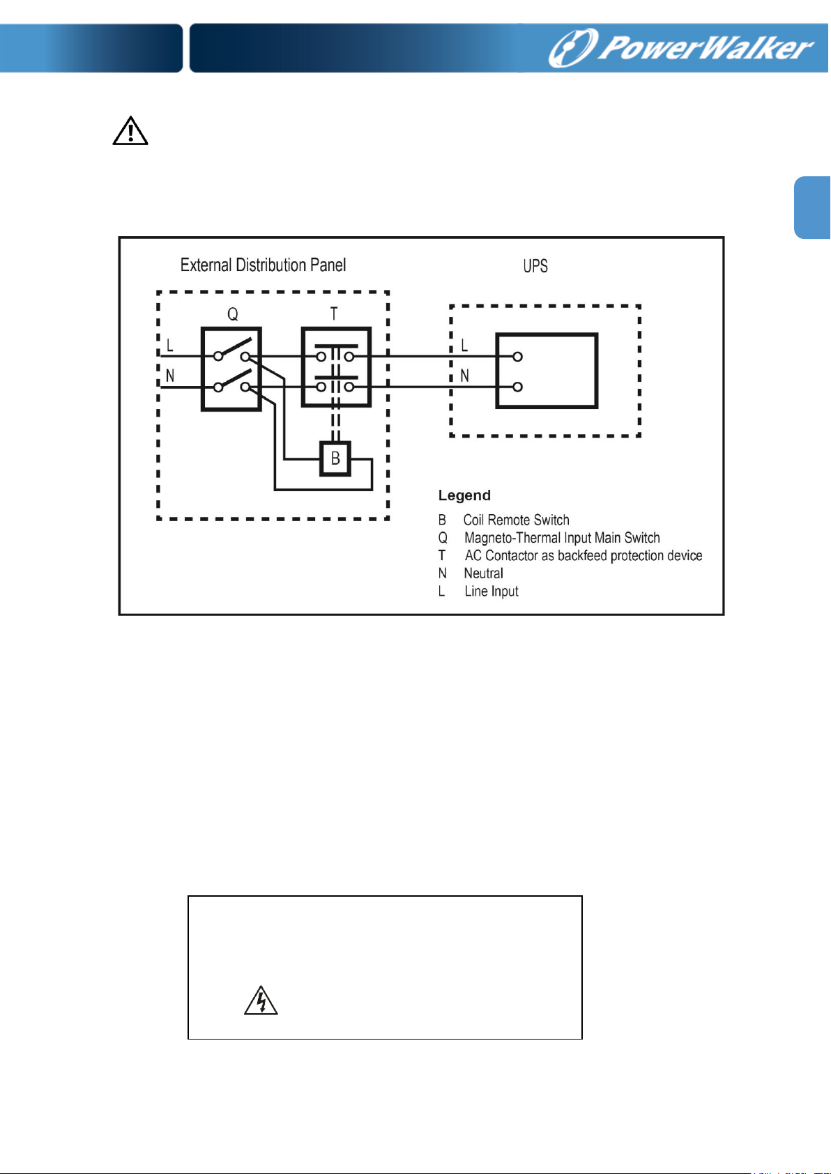
Before working on this circuit
- Isolate Uninterruptible Power System (UPS)
- Then check for Hazardous Voltage between all
terminals including the protective earth.
Risk of Voltage Backfeed
1-4. Connection Warnings
• There is no standard backfeed protection inside, please isolate the UPS before working according to this
circuit. The isolation device must be able to carry the UPS input current.
• This UPS should be connected with TN earthing system.
• The power supply for this unit must be single-phase rated in accordance with the equipment nameplate.
It also must be suitably grounded.
• Use of this equipment in life support applications where failure of this equipment can reasonably be
expected to cause the failure of the life support equipment or to significantly affect its safety or
effectiveness is not recommended. Do not use this equipment in the presence of a flammable anesthetic
mixture with air, oxygen or nitrous oxide.
• Connect your UPS power module’s grounding terminal to a grounding electrode conductor.
• The UPS is connected to a DC energy source (battery). The output terminals may be live when the UPS
is not connected to an AC supply.
3
Page 7

4
EN
* Safety
IEC/EN 62040-1
* EMI
Conducted Emission...............................:IEC/EN 62040-2
Category C3
Radiated Emission..................................:IEC/EN 62040-2
Category C3
*EMS
ESD.........................................................:IEC/EN 61000-4-2
Level 4
RS........................................................ ...:IEC/EN 61000-4-3
Level 3
EFT......................................................... :IEC/EN 61000-4-4
Level 4
SURGE................................................... :IEC/EN 61000-4-5
Level 4
CS........................................................... :IEC/EN 61000-4-6
Level 3
Power-frequency Magnetic field.............. :IEC/EN 61000-4-8
Level 4
Low Frequency Signals............................:IEC/EN 61000-2-2
Warning: This is a product for commercial and industrial application in the
second environment-installation restrictions or additional measures may be
needed to prevent disturbances.
1-5. Operation
Do not disconnect the earth conductor cable on the UPS or the building wiring terminals in any
time since this would cancel the protective earth of the UPS system and of all connected loads.
The UPS system features its own, internal current source (batteries). The UPS output sockets or
output terminal blocks may be electrically live even if the UPS system is not connected to the building
wiring outlet.
In order to fully disconnect the UPS system, first press the “OFF” button and then disconnect the
mains.
Ensure that no liquid or other foreign objects can enter into the UPS system.
The UPS can be operated by any individuals with no previous experience.
1-6. Standards
Page 8
EN
Model
Type
Model
Type
PowerWalker VFI
10000CRM LCD
Standard
model
PowerWalker VFI
10000CRM LCDL
Long-run
model
2. Installation and Operation
There are two different types of online UPS: standard and long-run models. Please refer to the following
model table.
2-1. Unpacking and Inspection
Unpack the package and check the package contents. The shipping package contains:
● One UPS
● One user manual
● One monitoring software CD
● One RS-232 cable (option)
● One USB cable
● One battery cable (option)
NOTE: Before installation, please inspect the unit. Be sure that nothing inside the package is damaged
during transportation. Do not turn on the unit and notify the carrier and dealer immediately if there is any
damage or lacking of some parts. Please keep the original package in a safe place for future use.
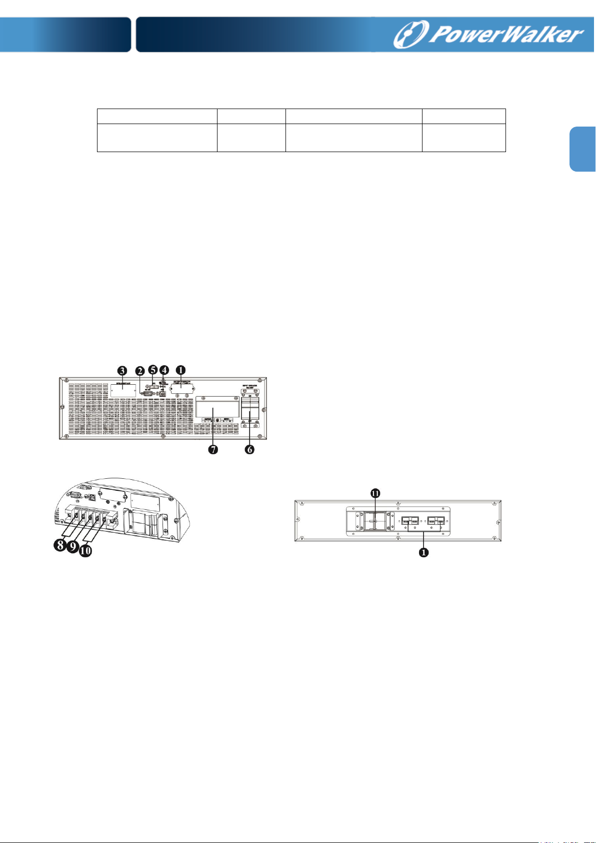
2-2. Rear Panel View
Diagram 1: PowerWalker VFI 10000CRM LCD (L) Rear Panel
Diagram 2: Input/Output Terminal Diagram 3: Battery Pack Rear Panel
1. External battery connector
2. RS-232 communication port
3. Intelligent slot
4. USB communication
5. Emergency power off function connector (EPO connector)
6. Input circuit breaker
7. Input/Output terminal (Refer to Diagram 2 for the details)
8. Output terminal
9. Grounding terminal
10. Utility input terminal
11. Battery pack output circuit breaker
5
Page 9
6
EN
Model
Wiring spec (AWG)
Input
Output
Battery
Ground
PowerWalker VFI 10000CRM LCD
8
8 8
PowerWalker VFI 10000CRM LCDL
8
8 8 8
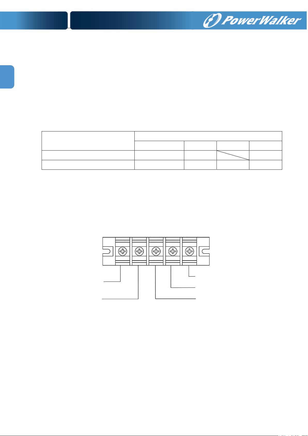
Input Neutral
Input Line
Ground
Output Line
Output Neutral
2-3. Single UPS Installation
Installation and wiring must be performed in accordance with the local electric laws/regulations and execute
the following instructions by professional personnel.
1) Make sure the mains wire and breakers in the building are in compliance with the standard of rated
capacity of UPS to avoid the hazards of electric shock or fire.
NOTE: Do not use the wall receptacle as the input power source for the UPS, as its rated current is less than
the UPS’s maximum input current. Otherwise the receptacle may be burned and destroyed.
2) Switch off the mains switch in the building before installation.
3) Turn off all the connected devices before connecting to the UPS.
4) Prepare wires based on the following table:
NOTE 1: It is recommended to use suitable wire in above table or thicker for safety and efficiency.
NOTE 2: The selections for color of wires should be followed by the local electrical laws and
regulations.
5) Remove the terminal block cover on the rear panel of UPS. Then connect the wires according to the
following terminal block diagrams: (Connect the earth wire first when making wire connection. Disconnect
the earth wire last when making wire disconnection!)
Terminal Block wiring diagram
NOTE 1: Make sure that the wires are connected tightly with the terminals.
NOTE 2: Please install the output breaker between the output terminal and the load, and the breaker
should be qualified with leakage current protective function if necessary.
Page 10
EN
6) Put the terminal block cover back to the rear panel of the UPS.
Warning: (Only for standard model)
● Make sure the UPS is not turned on before installation. The UPS should not be turned on during wiring
connection.
● Do not try to modify the standard model to the long-run model. Particularly, do not try to connect the
standard internal battery to the external battery. The battery type and voltage and numbers may be
different. If you connect them together, it maybe causes the hazard of electric shock or fire!
Warning: (Only for long-run model)
● Make sure a DC breaker or other protection device between UPS and external battery pack is installed. If
not, please install it carefully. Switch off the battery breaker before installation.
Warning:
● For standard battery pack, there are one DC breaker to disconnect the battery pack and the UPS. But for
other external battery pack, make sure a DC breaker or other protection device between UPS and
external battery pack is installed. If not, please install it carefully. Switch off the battery breaker before
installation.
NOTE: Set the battery pack breaker in “OFF” position and then install the battery pack.
● Pay highly attention to the polarity marking on external battery terminal block, and make sure the
correct battery polarity is connected. Wrong connection may cause permanent damage of the UPS.
● Make sure the protective earth ground wiring is correct. The current spec, color, position, connection and
conductance reliability of wire should be checked carefully.
● Make sure the utility input & output wiring is correct. The current spec, color, position, connection and
conductance reliability of wire should be checked carefully. Make sure the L/N terminal is correct, not
reverse or short-circuited.
2-4. Software Installation
For optimal computer system protection, install UPS monitoring software to fully configure UPS shutdown.
7
Page 11
8
EN
3. Operations
Button
Function
ON/Enter Button
Turn on the UPS: Press and hold the button more than 1s to turn on the UPS.
Enter Key: Press this button to confirm the selection in setting menu.
OFF/ESC Button
Turn off the UPS: Press and hold the button more than 1s to turn off the UPS.
Esc key: Press this button to return to last menu in setting menu.
Test/Up Button
Battery test: Press and hold the button more than 1s to test the battery while in
AC mode, or CVCF mode.
UP key: Press this button to display next selection in setting menu.
Mute/Down Button
Mute the alarm: Press and hold the button more than 1s to mute the buzzer.
Please refer to section 3-4 “Mute the buzzer” for details.
Down key: Press this button to display previous selection in setting menu.
Test/Up +
Mute/Down Button
Press and hold the two buttons simultaneous more than 1s to enter/escape the
setting menu.
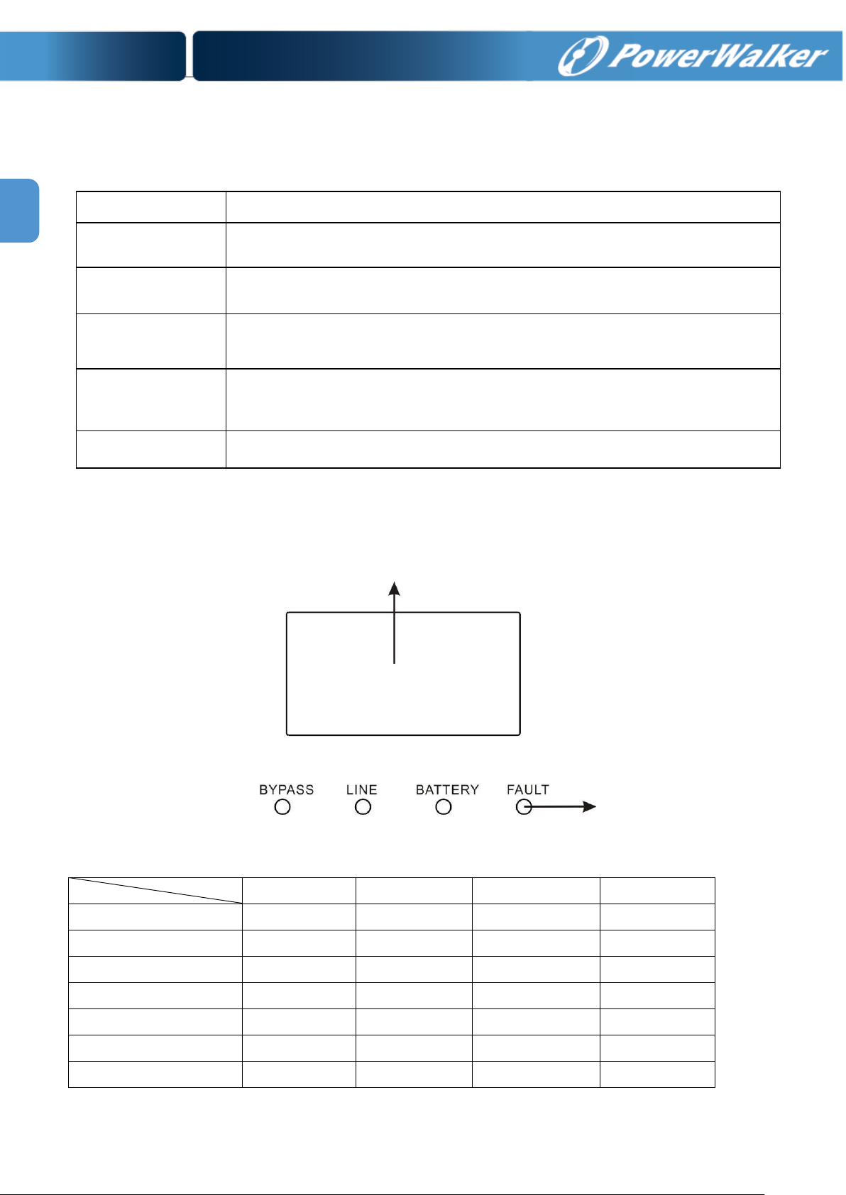
Mode LED
Bypass
Line
Battery
Fault
UPS Startup
● ● ●
●
Bypass mode
●
○ ○ ○
AC mode
○ ● ○
○
Battery mode
○
○ ● ○
CVCF mode
○ ● ○
○
Battery Test
● ● ●
○
Fault
○ ○ ○
●
LCD panel
LED indicators
3-1. Button Operation
* CVCF mode means converter mode.
3-2. LED Indicators and LCD Panel
LED Indicators:
There are 4 LEDs on front panel to show the UPS working status:
Note: ● means LED is lighting, and ○ means LED is faded.
Page 12
EN
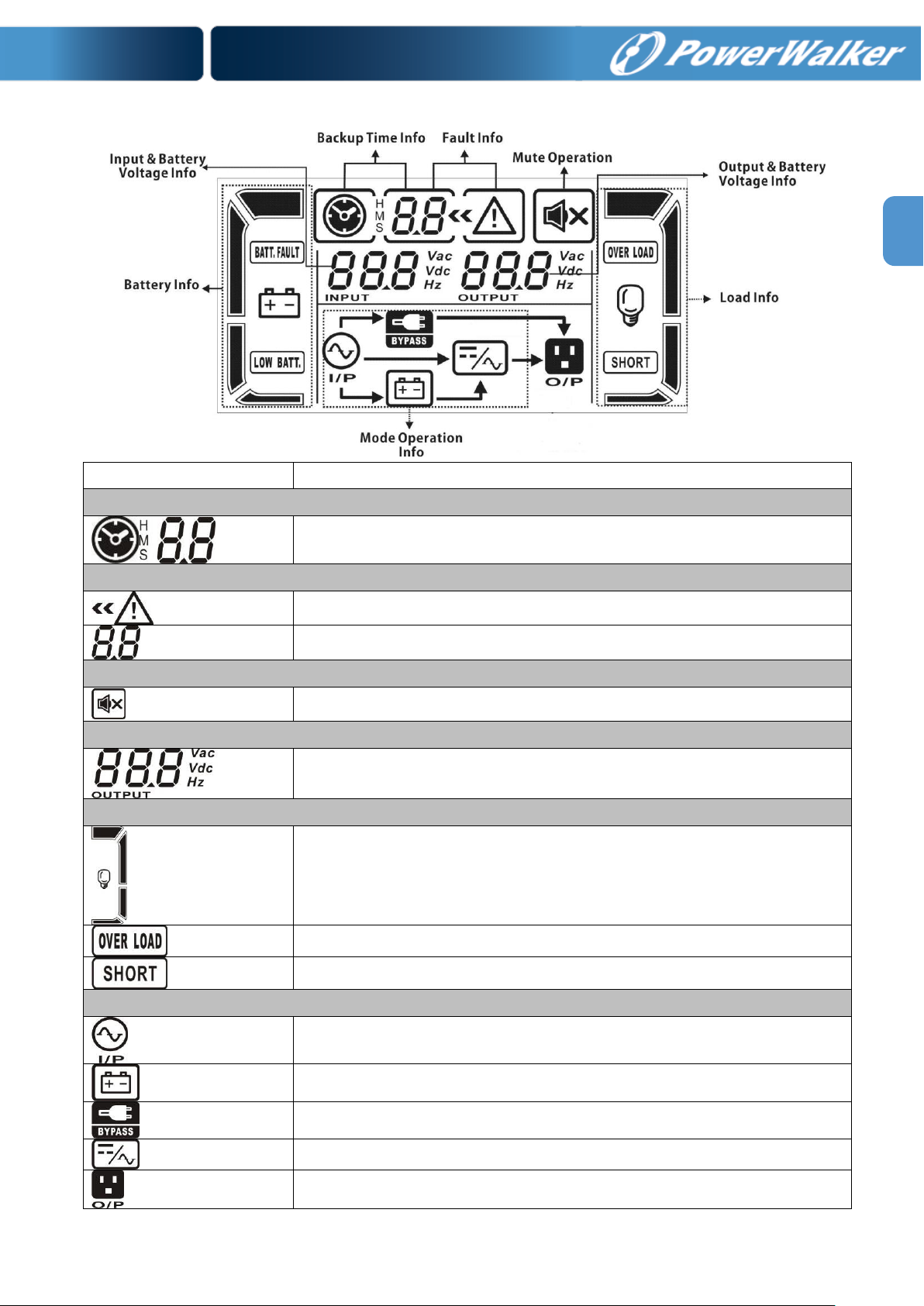
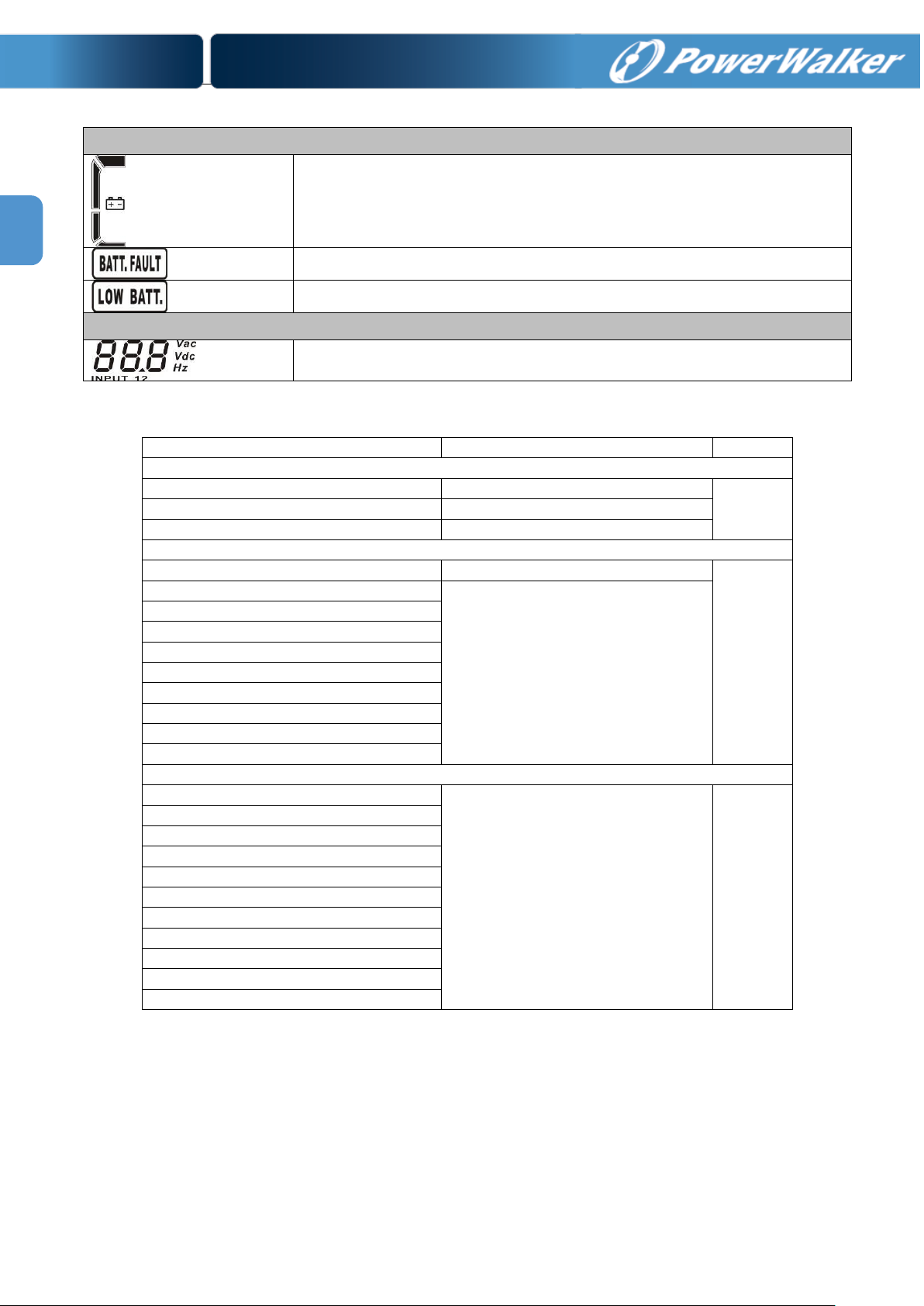
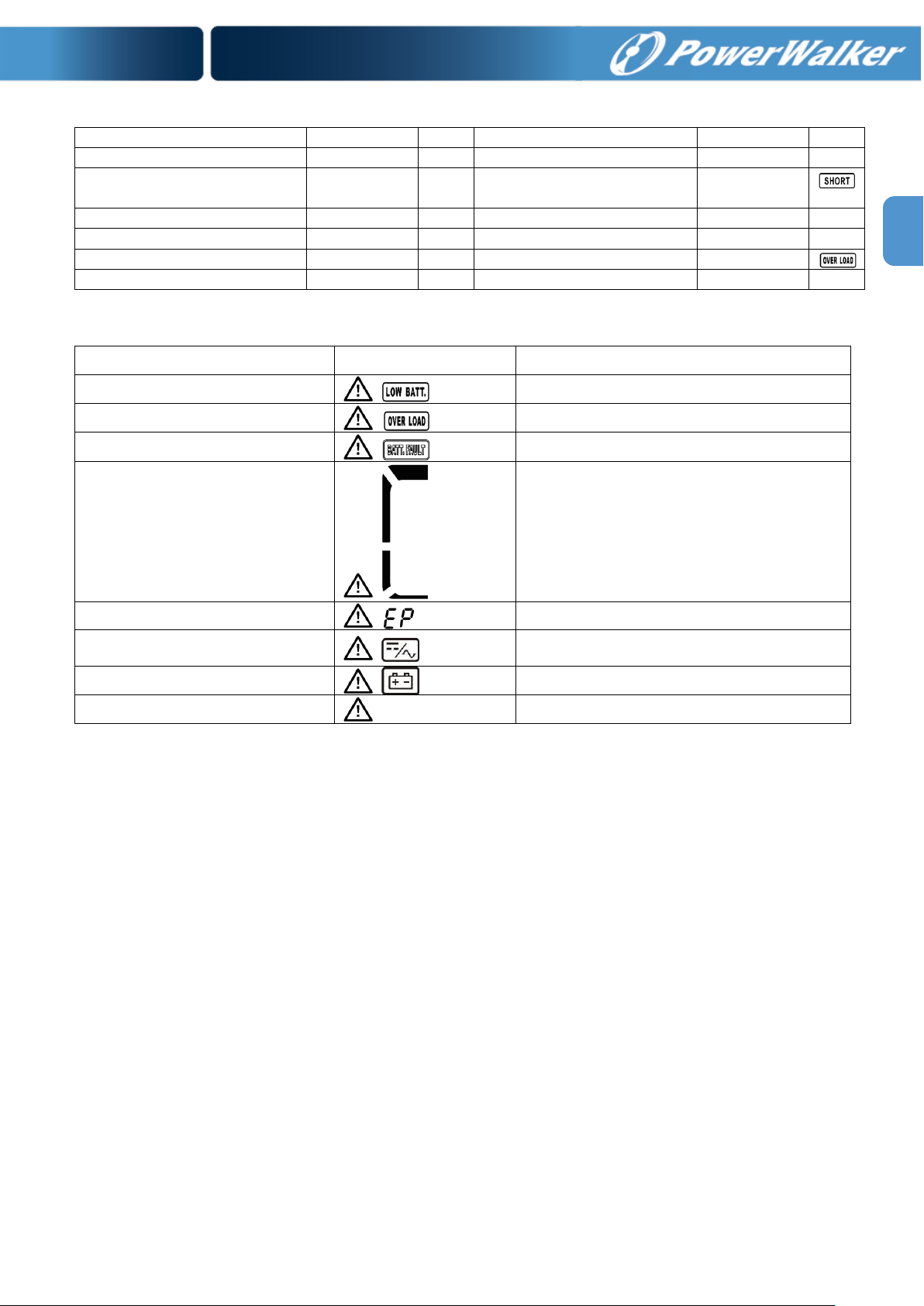
LCD Panel:
Display
Function
Backup time information
Indicates the backup time in numbers.
H: hours, M: minutes, S: seconds
Fault information
Indicates that the warning and fault occurs.
Indicates the fault codes, and the codes are listed in details in section 3-9.
Mute operation
Indicates that the UPS alarm is disabled.
Output & Battery voltage information
Indicates the output voltage, frequency or battery voltage.
Vac: output voltage, Vdc: battery voltage, Hz: frequency
Load information
Indicates the load level by 0-25%, 26-50%, 51-75%, and 76-100%.
Indicates overload.
Indicates the load or the output is short.
Mode operation information
Indicates the UPS connects to the mains.
Indicates the battery is working.
Indicates the bypass circuit is working.
Indicates the Inverter circuit is working.
Indicates the output is working.
9
Page 13
10
EN
Battery information
Indicates the Battery capacity by 0-25%, 26-50%, 51-75%, and 76-100%.
Indicates the battery is fault.
Indicates low battery level and low battery voltage.
Input & Battery voltage information
Indicates the input voltage or frequency or battery voltage.
Vac: Input voltage, Vdc: battery voltage, Hz: input frequency
Description
Buzzer status
Muted
UPS status
Bypass mode
Beeping once every 2 minutes
Yes
Battery mode
Beeping once every 4 seconds
Fault mode
Beeping continuously
Warning
Overload
Beeping twice every second
No
Low battery
Beeping once every second
Battery unconnected
Over charge
EPO enable
Fan failure/Over temperature
Charger failure
Overload 3 times in 30min
EPO status
Cover of maintain switch is open
Fault
Bus start failure
Beeping continuously
Yes
Bus over
Bus under
Bus unbalance
Inverter soft start failure
High Inverter voltage
Low Inverter voltage
Inverter output short circuited
Battery SCR short circuited
Over temperature
Overload
3-3. Audible Alarm
Page 14

EN
3-4. Single UPS Operation
1. Turn on the UPS with utility power supply (in AC mode)
1) After power supply is connected correctly, set the breaker of the battery pack at “ON” position (the
step only available for long-run model). Then, set the input breaker at “ON” position. At this time,
the fan is running and the UPS supplies power to the loads via the bypass. The UPS is operating in
Bypass mode.
NOTE: When UPS is in Bypass mode, the output voltage will directly power from utility after you
switch on the input breaker. In Bypass mode, the load is not protected by UPS. To protect your
precious devices, you should turn on the UPS. Refer to next step.
2) Press and hold the “ON” button for 1s to turn on the UPS and the buzzer will beep once.
3) A few seconds later, the UPS will enter to AC mode. If the utility power is abnormal, the UPS will
operate in Battery mode without interruption.
NOTE: When the UPS is running out battery, it will shut down automatically at Battery mode. When the
utility power is restored, the UPS will auto restart in AC mode.
2. Turn on the UPS without utility power supply (in Battery mode)
1) Make sure that the breaker of the battery pack is at “ON” position (only for long-run model).
2) Press and hold the “ON” button for 1s to turn on the UPS, and the buzzer will beep once.
3) A few seconds later, the UPS will be turned on and enter to Battery mode.
3. Connect devices to UPS
After the UPS is turned on, you can connect devices to the UPS.
1) Switch on the devices one by one and it will display total load level in LCD panel.
2) If it is necessary to connect the inductive loads such as a printer, the in-rush current should be
calculated carefully to see if it meets the capacity of the UPS, because the power consumption of
this kind of loads is too big.
3) If the UPS is overload, the buzzer will beep twice every second.
4) When the UPS is overload, please remove some loads immediately. It is recommended to have the
total loads connected to the UPS less than 80% of its nominal power capacity to prevent overload
for system safety.
5) If the overload time is over acceptable time listed in spec at AC mode, the UPS will automatically
transfer to Bypass mode. After the overload is removed, it will return to AC mode. If the overload
occurs 3 times in half hour, the UPS will be locked in Bypass mode. UPS can transfer to Line mode
only by manual restart. At this time, if bypass is enabled, the UPS will power to the load via bypass.
If bypass function is disabled or the input power is not within bypass acceptable range, it will cut off
output directly.
4. Charge the batteries
1) After the UPS is connected to the utility power, the charger will charge the batteries automatically
except in Battery mode or during battery self-test.
2) It’s suggested to charge batteries at least 10 hours before use. Otherwise, the backup time may be
shorter than expected time.
11
Page 15

12
EN
3) The charging current can be changed from 1A to 6A via LCD or software. Please make sure that the
charging current is suitable to battery specification.
5. Battery mode operation
1) When the UPS is in Battery mode, the buzzer will beep according to different battery capacity. If the
battery capacity is more than 25%, the buzzer will beep once every 4 seconds. If the battery
voltage drops to the alarm level, the buzzer will beep quickly (once every sec) to remind users that
the battery is at low level and the UPS will shut down automatically soon. Users could switch off
some non-critical loads to disable the shutdown alarm and prolong the backup time. If there is no
more load to be switched off at that time, you have to shut down all loads as soon as possible to
protect the devices or save data. Otherwise, there is a risk of data loss or power failure.
2) In Battery mode, if buzzer sound annoys, users can press the Mute button to mute the buzzer.
3) The backup time of the long-run model depends on the external battery capacity.
4) The backup time may vary from different environment temperature and load type.
5) When setting backup time for 16.5 hours (default value from LCD panel), after discharging 16.5
hours, UPS will shut down automatically to protect the battery. This battery discharge protection
can be enabled or disabled through LCD panel control. (Refer to 3-7 LCD setting section)
6. Turn off the UPS with utility power supply in AC mode
1) Turn off the inverter of the UPS by pressing “OFF” button for at least 1s, and then the buzzer will
beep once. The UPS will turn into Bypass mode.
NOTE 1: If the UPS has been set to enable the bypass output, it will bypass voltage from utility
power to output sockets and terminal even though you have turned off the UPS (inverter).
NOTE 2: After turning off the UPS, please be aware that the UPS is working at Bypass mode and
there is risk of power loss for connected devices.
2) In Bypass mode, output voltage of the UPS is still present. In order to cut off the output, switch off
the input breaker. A few seconds later, there is no display shown on the LCD panel and UPS is
complete off.
7. Turn off the UPS without utility power supply in Battery mode
1) Turn off the UPS by pressing “OFF” button for at least 1s, and then the buzzer will beep once.
2) Then UPS will cut off power to output and there is no display shown on the display panel.
8. Mute the buzzer
1) To mute the buzzer, please press the “Mute” button for at least 1s. If you press it again after the
buzzer is muted, the buzzer will beep again.
2) Some warning alarms can’t be muted unless the error is fixed. Please refer to section 3-3 for the
details.
9. Operation in warning status
1) When Fault LED flashes and the buzzer beeps once every second, it means that there are some
problems for UPS operation. Users can get the fault code from LCD panel. Please check the trouble
shooting table in chapter 4 for details.
2) Some warning alarms can’t be muted unless the error is fixed. Please refer to section 3-3 for the
details.
Page 16
EN
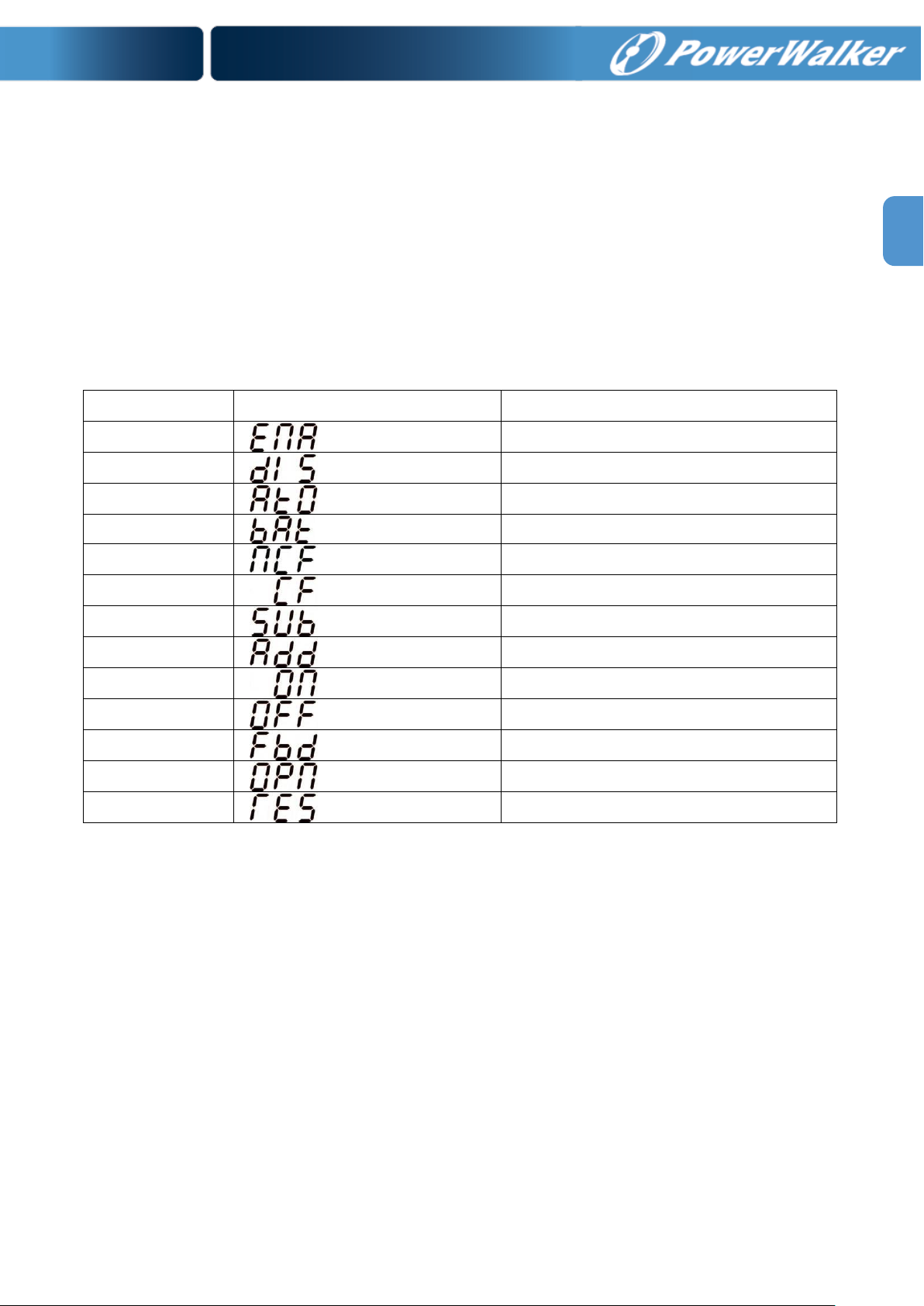
Abbreviation
Display content
Meaning
ENA
Enable
DIS
Disable
ATO
Auto
BAT
Battery
NCF
Normal mode (not CVCF mode)
CF
CVCF mode
SUB
Subtract
ADD
Add
ON
On
OFF
Off
FBD
Not allowed
OPN
Allow
RES
Reserved
10. Operation in Fault mode
1) When Fault LED illuminates and the buzzer beeps continuously, it means that there is a fatal error in
the UPS. Users can get the fault code from display panel. Please check the trouble shooting table
in chapter 4 for details.
2) Please check the loads, wiring, ventilation, utility, battery and so on after the fault occurs. Don’t try
to turn on the UPS again before solving the problems. If the problems can’t be fixed, please contact
the distributor or service people immediately.
3) For emergency case, please cut off the connection from utility, external battery and output
immediately to avoid more risk or danger.
3-5. Abbreviation Meaning in LCD Display
13
Page 17
14
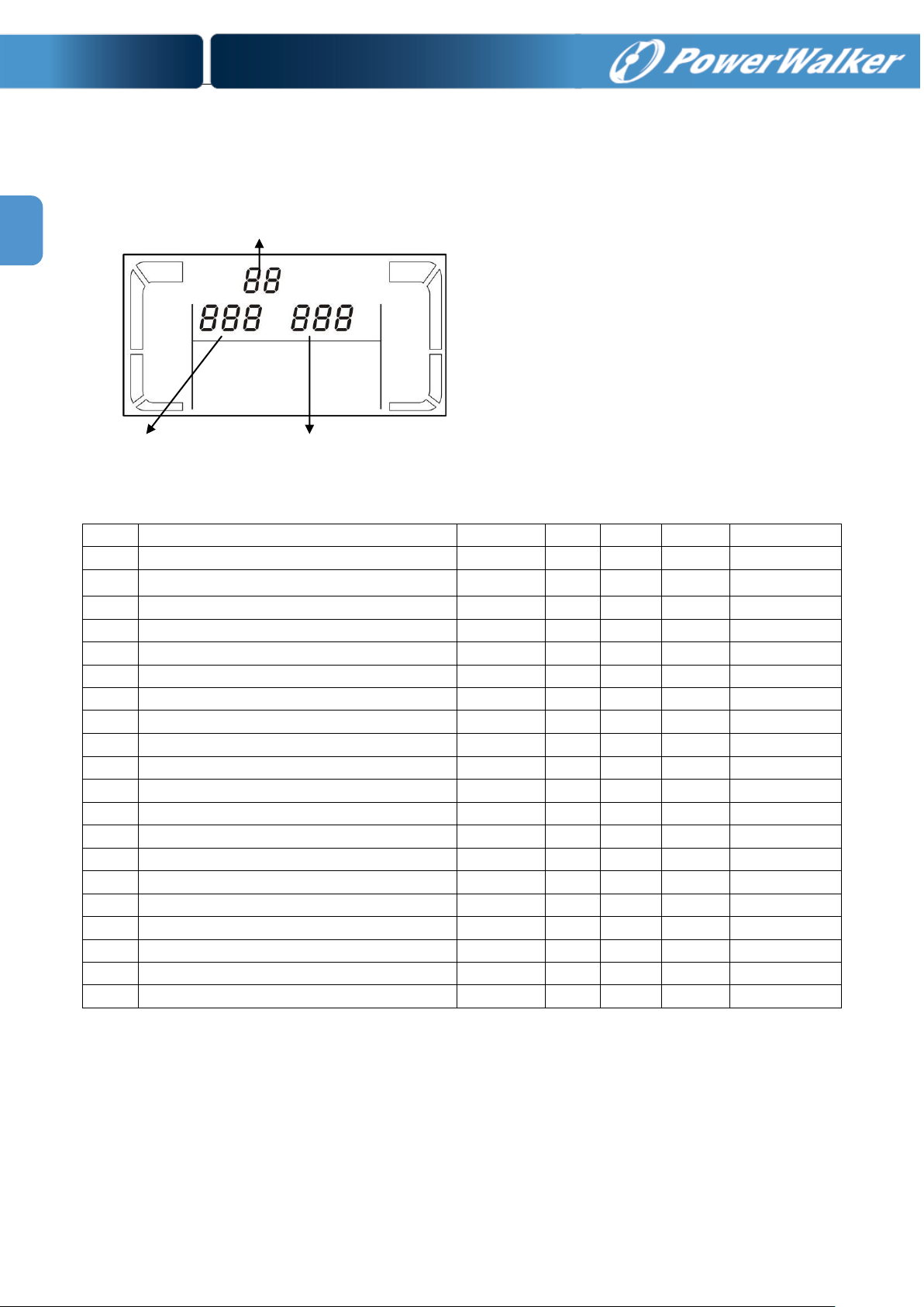
EN
Parameter 1: It’s for program alternatives. Refer
to below table for the programs to set up.
Parameter 2 and parameter 3 are the setting
options or values for each program.
Note: Please select “Up” or “Down” button to
change the programs or parameters.
Code
Description
Bypass
AC
CVCF
Battery
Battery Test
01
Output voltage
Y
02
Output frequency
Y
03
Voltage range for bypass
Y
04
Frequency range for bypass
Y
05
Reserved
06
Reserved
07
Reserved
08
Bypass mode setting
Y
Y
09
Battery maximum discharge time setting
Y Y Y Y Y
10
Reserved
11
Reserved
12
Reserved
13
Battery voltage Calibration
Y Y Y Y Y
14
Reserved
15
Inverter voltage Calibration
Y Y Y
16
Floating charger voltage adjustment
Y Y Y Y Y
17
Constant charger voltage adjustment
Y Y Y Y Y
18
Charger maximum current setting
Y Y Y Y Y
19
Battery capacity and groups setting
Y Y Y Y Y
20
Backup time calibration
Y Y Y Y Y
Parameter 1
Parameter 2
Parameter 3
3-6. LCD Setting
There are three parameters to set up the UPS. Refer to following diagram.
Programs available list for parameter 1:
*Y means that this program can be set in this mode.
Page 18
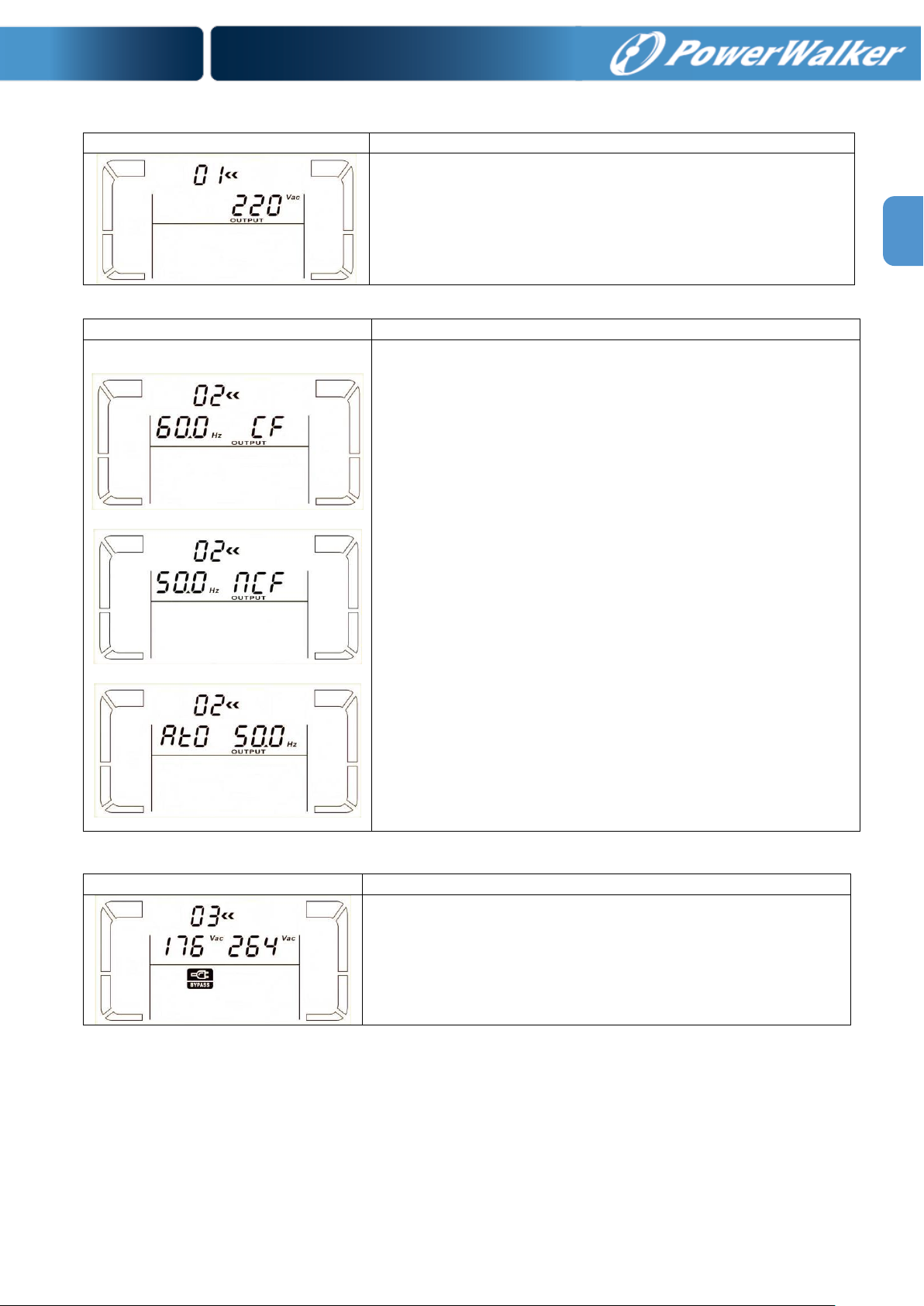
EN
01: Output voltage
Interface
Setting
Parameter 3: Output voltage
You may choose the following output voltage in parameter 3:
208: Presents output voltage is 208Vac
220: Presents output voltage is 220Vac
230: Presents output voltage is 230Vac
240: Presents output voltage is 240Vac
Interface
Setting
60 Hz, CVCF mode
50 Hz, Normal mode
ATO
Parameter 2: Output Frequency
Setting the output frequency. You may choose following three
options in parameter 2:
50.0Hz: The output frequency is setting for 50.0Hz.
60.0Hz: The output frequency is setting for 60.0Hz.
ATO: If selected, output frequency will be decided according to
the latest normal utility frequency. If it is from 46Hz to 54Hz, the
output frequency will be 50.0Hz. If it is from 56Hz to 64Hz, the
output frequency will be 60.0Hz. ATO is default setting.
Parameter 3: Frequency mode
Setting output frequency at CVCF mode or non-CVCF mode. You
may choose following two options in parameter 3:
CF: Setting UPS to CVCF mode. If selected, the output frequency
will be fixed at 50Hz or 60Hz according to setting in parameter 2.
The input frequency could be from 46Hz to 64Hz.
NCF: Setting UPS to normal mode (non-CVCF mode). If selected,
the output frequency will synchronize with the input frequency
within 46~54 Hz at 50Hz or within 56~64 Hz at 60Hz according to
setting in parameter 2. If 50 Hz selected in parameter 2, UPS will
transfer to battery mode when input frequency is not within
46~54 Hz. If 60Hz selected in parameter 2, UPS will transfer to
battery mode when input frequency is not within 56~64 Hz.
*If Parameter 2 is ATO, the Parameter 3 will show the current
frequency.
Interface
Setting
Parameter 2: Set the acceptable low voltage for bypass. Setting
range is from 110V to 209V and the default value is 110V.
Parameter 3: Set the acceptable high voltage for bypass. Setting
range is from 231V to 276V and the default value is 264V.
02: Output frequency
03: Voltage range for bypass
15
Page 19
16
EN
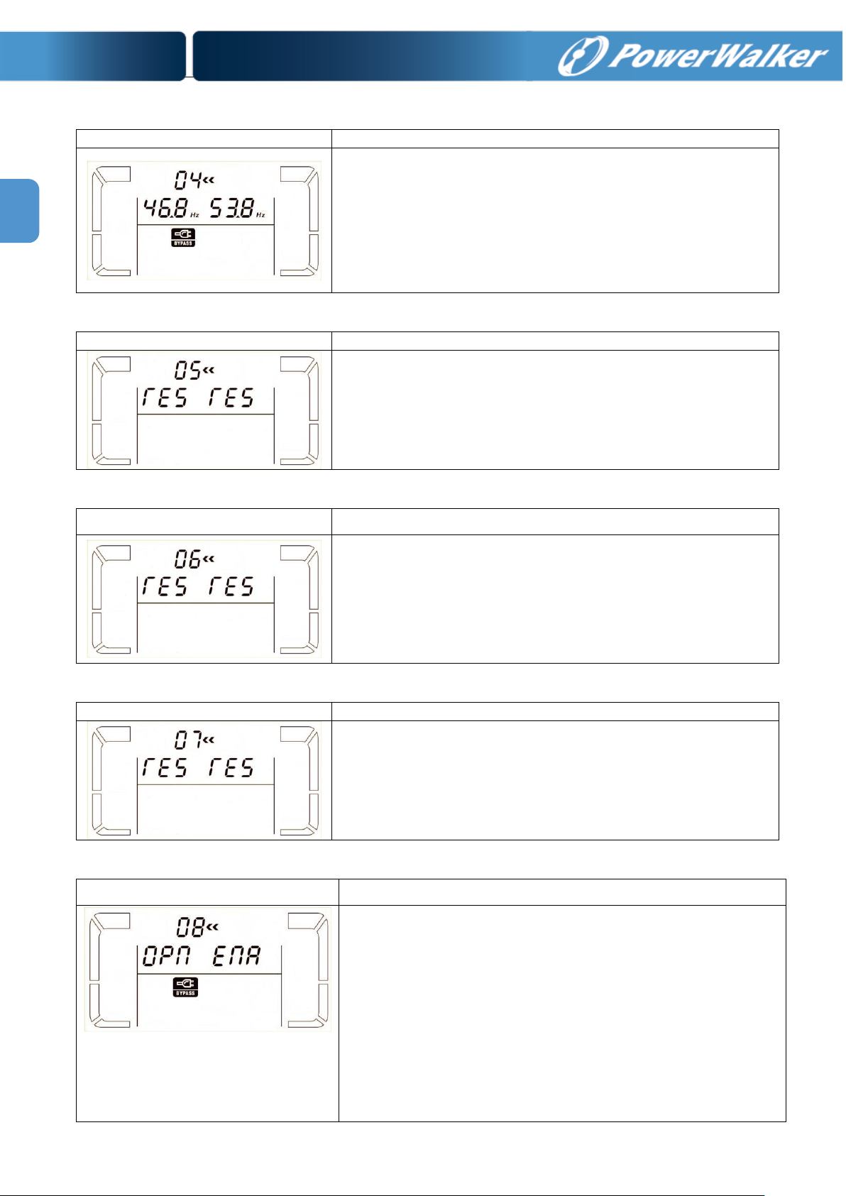
04: Frequency range for bypass
Interface
Setting
Parameter 2: Set the acceptable low frequency for bypass.
50 Hz system: Setting range is from 46.0Hz to 49.0Hz.
60 Hz system: Setting range is from 56.0Hz to 59.0Hz.
The default value is 46.0Hz/56.0Hz.
Parameter 3: Set the acceptable high frequency for bypass.
50 Hz: Setting range is from 51.0Hz to 54.0 Hz.
60 Hz: Setting range is from 61.0Hz to 64.0Hz.
The default value is 54.0Hz/64.0Hz.
Interface
Setting
reserved
Interface
Setting
reserved
Interface
Setting
reserved
Interface
Setting
Parameter 2:
OPN: Bypass allowed. When selected, UPS will run at Bypass
mode depending on bypass enabled/disabled setting.
FBD: Bypass not allowed. When selected, it’s not allowed for
running in Bypass mode under any situations.
Parameter 3:
ENA: Bypass enabled. When selected, Bypass mode is activated.
DIS: Bypass disabled. When selected, automatic bypass is
acceptable, but manual bypass is not allowed. Manual bypass
means users manually operate UPS for Bypass mode. For
example, pressing OFF button in AC mode to turn into Bypass
mode.
05: reserved
06: reserved
07: reserved
08: Bypass mode setting
Page 20
EN
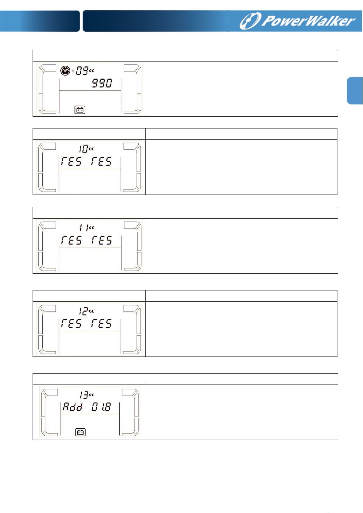
Interface
Setting
Parameter 3:
000~999: Set the maximum discharge time from 0 min. to 999
min. UPS will shut down to protect battery after discharge time
arrives. The default value is 990 min.
DIS: Disable battery discharge protection and backup time will
depend on battery capacity.
Interface
Setting
reserved
Interface
Setting
reserved
Interface
Setting
reserved
Interface
Setting
Parameter 2: Select “Add” or “Sub” function to calibrate battery
voltage to real figure.
Parameter 3: The voltage setting range is from 0V to 5.7V. The
default value is 0V.
09: Battery maximum discharge time setting
10: reserved
11: reserved
12: reserved
13: Battery voltage calibration
17
Page 21
18
EN
14: reserved
Interface
Setting
reserved
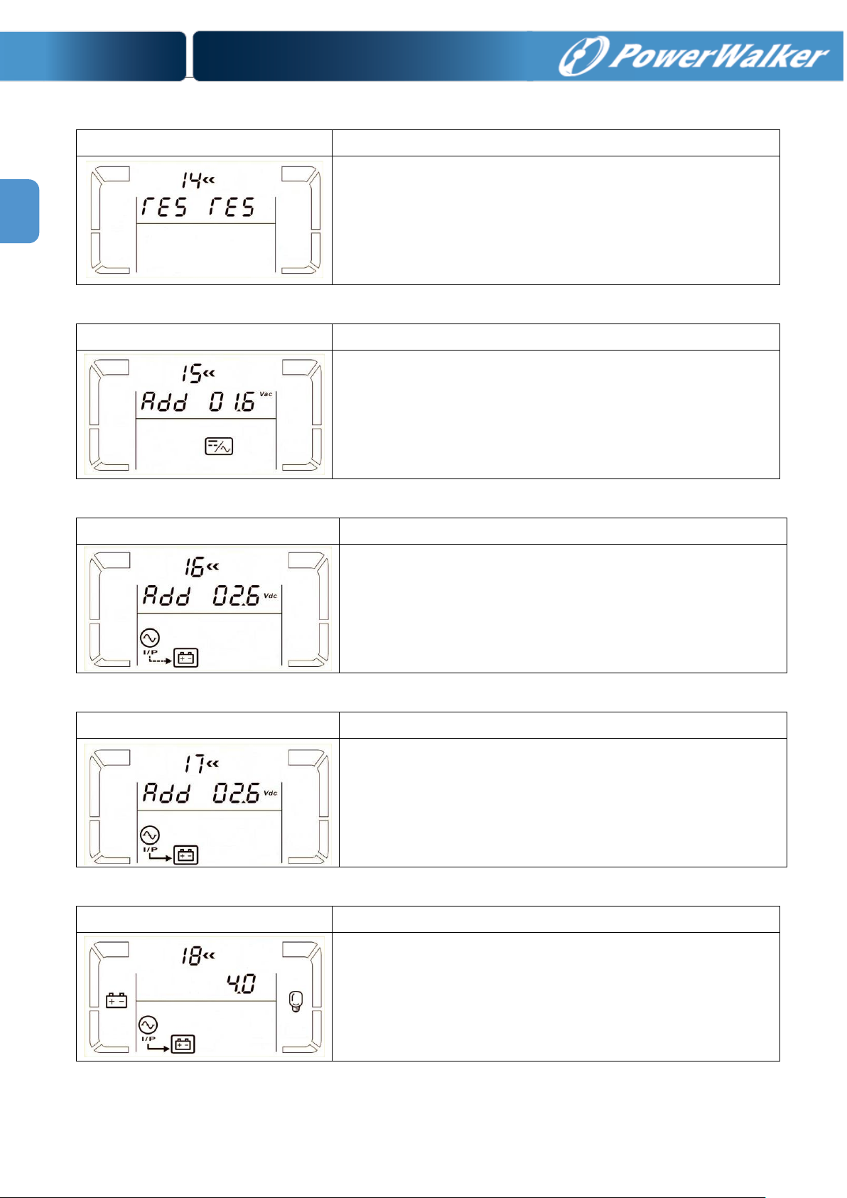
Interface
Setting
Parameter 2: you may choose Add or Sub to calibrate inverter
voltage
Parameter 3: The voltage setting range is from 0V to 6.4V. The
default value is 0V.
Interface
Setting
Parameter 2: you may choose Add or Sub to adjust floating
charger voltage.
Parameter 3: the voltage range is from 0V to 6.4V, the default
value is 0V.
Interface
Setting
Parameter 2: you may choose Add or Sub to adjust constant
charger voltage.
Parameter 3: the voltage range is from 0V to 3.2V, the default
value is 0V.
Interface
Setting
Parameter 3:
The maximum charging current could be adjusted.
Default value is 4A for long run model and 1A for standard model.
The available options are 1A, 2A, 4A and 6A.
6A is only available for the UPS with 16 pieces of batteries.
15: Inverter voltage calibration
16: Floating charger voltage adjustment
17: Constant charger voltage adjustment
18: Maximum charger current setting
Page 22
EN
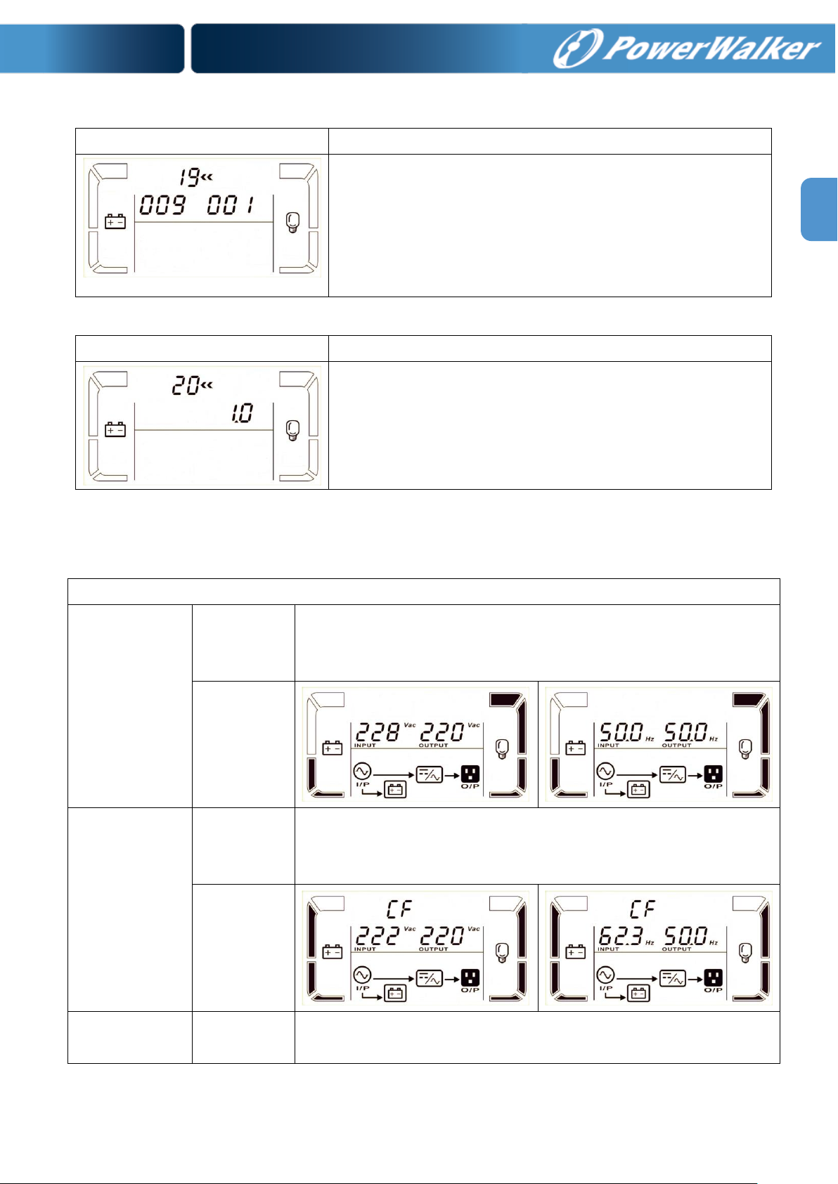
19: Battery capacity and groups setting
Interface
Setting
Parameter 2:
Set the battery capacity such as 7AH, 9AH, 10AH, 12AH, 17AH,
26AH, 40AH, 65AH, 100AH and so on.
The default value is 9AH.
Parameter 3:
Set battery group range from 1 to 6.
The default value is 1 group.
These parameters are for the battery backup time calculation.
Interface
Setting
Parameter 3:
Calibrate the displayed backup time by adjusting this multiplier
factor. The formulation is listed below:
Displayed backup time=Original calculated backup time x
Multiplier factor
The default value of multiplier factor is 1.0 and the setting range is
from 0.5 to 2.
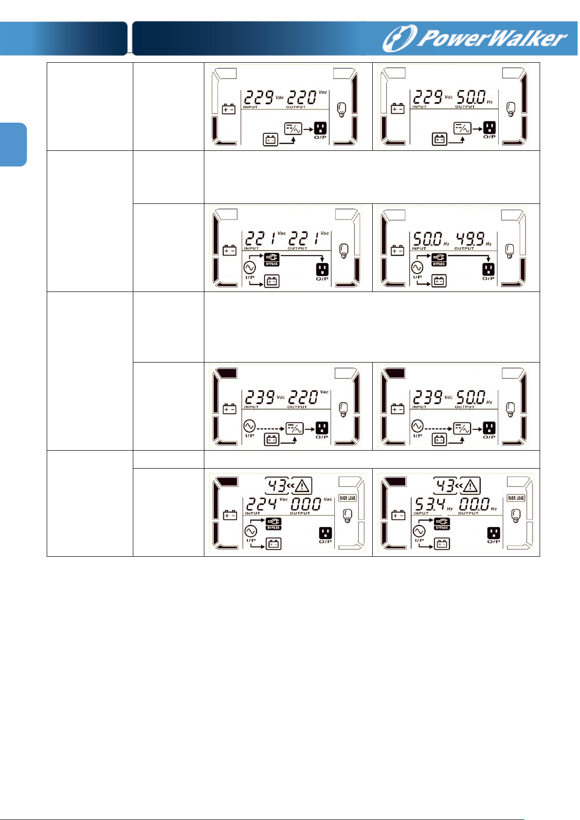
Operating mode/status
AC mode
Description
When the input voltage is within acceptable range, UPS will provide pure
and stable AC power to output. The UPS will also charge the battery at
AC mode.
LCD display
CVCF mode
Description
When input frequency is within 46 to 64Hz, the UPS can be set at a
constant output frequency, 50 Hz or 60 Hz. The UPS will still charge
battery under this mode.
LCD display
Battery mode
Description
When the input voltage is beyond the acceptable range or power failure,
UPS will backup power from battery and alarm will beep every 4 seconds.
20: Backup time calibration
3-7. Operating Mode/Status Description
19
Page 23
20
EN
LCD display
Bypass mode
Description
When input voltage is within acceptable range and bypass is enabled,
turn off the UPS and it will enter Bypass mode. Alarm beeps every two
minutes.
LCD display
Battery Test
Description
When UPS is in AC mode or CVCF mode, press “Test” key for more than
1s. Then, the UPS will beep once and start “Battery Test”. The line
between I/P and inverter icons will blink to remind users. This operation
is used to check the battery status.
LCD display
Fault status
Description
When UPS has fault happened, it will display fault codes in LCD panel.
LCD display
Page 24
EN
3-8. Fault Code
Fault event
Fault code
Icon
Fault event
Fault code
Icon
Bus start failure
01
None
Low Inverter voltage
13
None
Bus over
02
None
Inverter output short
circuited
14
Bus under
03
None
Battery SCR short circuited
21
None
Bus unbalance
04
None
Over temperature
41
None
Inverter soft start failure
11
None
Overload
43
High Inverter voltage
12
None
Warning
Icon (flashing)
Alarm
Battery low
Beeping every second
Overload
Beeping twice every second
Battery unconnected
Beeping every second
Over charge
Beeping every second
EPO enable
Beeping every second
Over temperature
Beeping every second
Charger failure
Beeping every second
Overload 3 times in 30min
Beeping every second
3-9. Warning Indicator
21
Page 25
22
EN
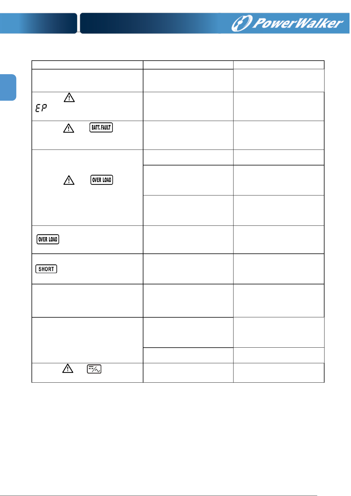
Symptom
Possible cause
Remedy
No indication and alarm in the front
display panel even though the mains is
normal.
The AC input power is not
connected well.
Check if input cable firmly
connected to the mains.
The icon and the warning code
flash on LCD display and alarm
beeps every second.
EPO function is enabled.
Set the circuit in closed
position to disable EPO
function.
The icon and flash on
LCD display and alarm beeps every
second.
The external or internal
battery is incorrectly
connected.
Check if all batteries are
connected well.
The icon and flash on
LCD display and alarm beeps twice
every second.
UPS is overload.
Remove excess loads from UPS
output.
UPS is overloaded. Devices
connected to the UPS are fed
directly by the electrical
network via the Bypass.
Remove excess loads from UPS
output.
After repetitive overloads, the
UPS is locked in the Bypass
mode. Connected devices are
fed directly by the mains.
Remove excess loads from UPS
output first. Then shut down
the UPS and restart it.
Fault code is shown as 43. The icon
lights on LCD display and
alarm beeps continuously.
UPS is overload too long and
becomes fault. Then UPS shut
down automatically.
Remove excess loads from UPS
output and restart it.
Fault code is shown as 14, the icon
lights on LCD display, and
alarm beeps continuously.
The UPS shut down
automatically because short
circuit occurs on the UPS
output.
Check output wiring and if
connected devices are in short
circuit status.
Other fault codes are shown on LCD
display and alarm beeps continuously.
A UPS internal fault has
occurred.
Contact your dealer
Battery backup time is shorter than
nominal value
Batteries are not fully charged
Charge the batteries at least 7
hours and then check capacity.
If the problem still persists,
consult your dealer.
Batteries defect
Contact your dealer to replace
the battery.
The icon and flash on LCD
display and alarm beeps every second.
The UPS temperature is too
high.
Check fans and notify dealer.
4. Trouble Shooting
If the UPS system does not operate correctly, please solve the problem by using the table below.
Page 26

EN
Storage Temperature
Recharge Frequency
Charging Duration
-25°C - 40°C
Every 3 months
1-2 hours
40°C - 45°C
Every 2 months
1-2 hours
5. Storage and Maintenance
5-1. Storage
Before storing, charge the UPS at least 7 hours. Store the UPS covered and upright in a cool, dry
location. During storage, recharge the battery in accordance with the following table:
5-2. Maintenance
The UPS system operates with hazardous voltages. Repairs may be carried out only by qualified
maintenance personnel.
Even after the unit is disconnected from the mains, components inside the UPS system are still
connected to the battery packs which are potentially dangerous.
Before carrying out any kind of service and/or maintenance, disconnect the batteries and verify that
no current is present and no hazardous voltage exists in the terminals of high capability capacitor such as
BUS-capacitors.
Only persons are adequately familiar with batteries and with the required precautionary measures
may replace batteries and supervise operations. Unauthorized persons must be kept well away from the
batteries.
Verify that no voltage between the battery terminals and the ground is present before maintenance
or repair. In this product, the battery circuit is not isolated from the input voltage. Hazardous voltages may
occur between the battery terminals and the ground.
Batteries may cause electric shock and have a high short-circuit current. Please remove all
wristwatches, rings and other metal personal objects before maintenance or repair, and only use tools
with insulated grips and handles for maintaining or repairing.
When replace the batteries, install the same number and same type of batteries.
Do not attempt to dispose of batteries by burning them. This could cause battery explosion. The
batteries must be rightly deposed according to local regulation.
Do not open or destroy batteries. Escaping electrolyte can cause injury to the skin and eyes. It may
be toxic.
Please replace the fuse only with the same type and amperage in order to avoid fire hazards.
Do not disassemble the UPS system.
23
Page 27

24
EN
6. Specifications
MODEL
PowerWalker VFI 10000CRM LCD
CAPACITY*
10000 VA / 8000 W
INPUT
Voltage Range
Low Line Loss
110 VAC ± 3 % at 50% Load;
176 VAC ± 3 % at 100% Load
Low Line Comeback
Low Line Loss Voltage + 10V
High Line Loss
300 VAC ± 3 %
High Line Comeback
High Line Loss Voltage - 10V
Frequency Range
46Hz ~ 54 Hz @ 50Hz system
56Hz ~ 64 Hz @ 60Hz system
Phase
Single phase with ground
Power Factor
≧ 0.99 at 100% Load
OUTPUT
Output voltage
208/220/230/240VAC
AC Voltage Regulation
± 1%
Frequency Range
(Synchronized Range)
46Hz ~ 54 Hz @ 50Hz system
56Hz ~ 64 Hz @ 60Hz system
Frequency Range (Batt. Mode)
50 Hz ± 0.1 Hz or 60Hz ± 0.1 Hz
Overload
AC mode
100%~110%: 30min; 110%~130%: 5min; >130% : 10sec
Battery mode
100%~110%: 3min; 110%~130%: 30sec; >130% : 10sec
Current Crest Ratio
3:1 max
Harmonic Distortion
≦ 3 % THD (Linear Load)
≦ 5 % THD (Non-linear Load)
Transfer Time
Line Battery
0 ms
Inverter Bypass
0 ms
EFFICIENCY
AC mode
> 93%
Battery Mode
> 91%
BATTERY
Standard
Model
Type & Numbers
12 V / 9 Ah x 16
Recharge Time
9 hours recover to 90% capacity
Charging Current
Default : 1 A ± 10%
Max.: 1A, 2A (Adjustable)
Charging Voltage
218.4V ± 1%
Long-run
Model
Type
Depending on applications
Numbers
16
Charging Current
Default: 4 A ± 10%
Max.: 1A, 2A, 4A, 6A (Adjustable)
Charging Voltage
218.4V ± 1%
PHYSICAL
Standard
Model
Dimension,DXWXH(mm)
UPS unit: 580 x 438 x 133 [3U]
Battery pack: 668 x 438 x 88 [2U]
Net Weight (kgs)
UPS unit: 18
Battery pack: 48
Long-run
Model
Dimension, DXWXH(mm)
580 x 438 x 133 [3U]
Net Weight (kgs)
18
ENVIRONMENT
Operation Temperature
0 ~ 40°C
(battery life cycle will be shorten when temperature is above 25°C)
Operation Humidity
<95 % and non-condensing
Operation Altitude**
<1000m
Acoustic Noise Level
Less than 58dB @ 1 Meter
MANAGEMENT
Smart RS-232 or USB
Supports Windows® 2000/2003/XP/Vista/2008, Windows® 7/8, Linux, Unix, and
MAC
Optional SNMP
Power management from SNMP manager and web browser
* Derate capacity to 60% of capacity in CVCF mode and to 90% when the output voltage is adjusted to 208VAC.
**If the UPS is installed or used in a place where the altitude is above than 1000m, the output power must be derated one percent per 100m.
***Product specifications are subject to change without further notice.
Page 28

Online-USV
PowerWalker VFI 10000CRM LCD
DE
Bedienungsanleitung
Unterbrechungsfreie Stromversorgung (USV)
Page 29

Page 30

0
DE
Bitte beachten Sie strikt alle Warnhinweise und
Bedienungsanleitungen in diesem Handbuch.
Verwahren Sie diese Anleitung gut auf und lesen
sorgfältig die folgenden Anweisungen, bevor Sie
das Gerät installieren. Nehmen Sie das Gerät erst
in Betrieb, wenn Sie alle Sicherheitshinweise und
die Bedienungsanleitung sorgfältig durchgelesen
haben.
Page 31

Inhaltsverzeichnis
Contents
1. SICHERHEITS- UND EMV-HINWEISE ....................................................................................................................... 2
1-1. TRANSPORT UND LAGERUNG .......................................................................................................................................... 2
1-2. VORBEREITUNG ............................................................................................................................................................. 2
1-3. INSTALLATION ............................................................................................................................................................... 2
1-4. ANSCHLUSSWARNUNGEN ................................................................................................................................... 3
1-5. BETRIEB ........................................................................................................................................................................ 4
1-6. STANDARDS ................................................................................................................................................................... 4
2. INSTALLATION UND BETRIEB ................................................................................................................................... 5
2-1. AUSPACKEN UND ÜBERPRÜFEN ....................................................................................................................................... 5
2-2. RÜCKWANDANSICHT ...................................................................................................................................................... 5
2-3. USV EINZELINSTALLATION ............................................................................................................................................. 6
2-4. SOFTWAREINSTALLATION ............................................................................................................................................... 7
3. BETRIEB............................................................................................................................................................................ 8
DE
3-1. TASTENBEDIENUNG ........................................................................................................................................................ 8
3-2. LED-ANZEIGE UND LCD-PANEL ..................................................................................................................................... 8
3-3. AKUSTISCHER ALARM .................................................................................................................................................. 11
3-4. USV EINZELPLATZBETRIEB ........................................................................................................................................... 12
3-5. BEDEUTUNG DER AB K ÜRZ U N G EN AU F D EM LCD-DISPLAY .............................................................................................. 14
3-6. LCD-EINSTELLUNG...................................................................................................................................................... 15
3-7. BETRIEBSMODUS/STATUSBESCHREIBUNG ...................................................................................................................... 20
3-8. FEHLERCODE ............................................................................................................................................................... 22
3-9. WARNANZEIGE ............................................................................................................................................................ 22
4. FEHLERBEHEBUNG .................................................................................................................................................... 23
5. LAGERUNG UND INSTANDHALTUNG .................................................................................................................... 24
5-1. LAGERUNG .................................................................................................................................................................. 24
5-2. WARTUNG ................................................................................................................................................................... 24
6. SPEZIFIKATIONEN ...................................................................................................................................................... 25
1
Page 32

2
DE
1. Sicherheits- und EMV-Hinweise
Bitte lesen Sie die folgenden Sicherheitshinweise und die Bedienungsanleitung vor der Installation und
Erstbenutzung aufmerksam durch!
1-1. Transport und Lagerung
Bitte transportieren Sie die USV nur in der Originalverpackung, um sie vor Stößen zu schützen.
Die USV muss in einem trockenen und gut belüfteten Raum aufbewahrt werden.
1-2. Vorbereitung
Es kann Ko ndensation auftreten, wenn die US V direkt von einer kalten in eine w arme Umgebung
bewegt wird. Die USV muss absolut trocken sein, bevor sie installiert wird. Lassen Sie der USV
mindestens zwei Stunden Zeit sich zu akklimatisieren.
Betreiben Sie das Gerät nicht in der Nähe von W asser oder in einer feuchten Umgebung.
Stellen Sie das USV-System nicht in der Nähe von Wärmequellen auf oder setzen Sie es nicht
direkter Sonneneinstrahlung aus.
Halten Sie die Ventilationsöffnungen des USV-Gehäuses frei.
1-3. Installation
Schließen Sie keine Geräte an die Ausgangsbuchsen oder -klemmen an, die die USV überlasten
(z.B. Geräte mit hoher Leistung).
Platzieren Sie Kabel so, dass niemand darauf treten oder darüber stolpern kann.
Halten Sie die Ventilationsöffnungen des USV-Gehäuses frei. Die USV muss an einem Ort mit
guter Belüftung installiert werden. Achten Sie auf jeder Seite auf genügend Platz für die Belüftung.
Die USV ist mit Erdungsklemmen im Endkonfigurationssystem ausgestattet, mit
Potenzialausgleich zur externen USV-Batteriebox.
Die USV darf nur von qualifiziertem Fachpersonal installiert werden.
Für den Kurzschlussschutz sind bauseits Sicherungen und Lasttrennschalter erforderlich.
Eine integrierte Notvorrichtung welche verhindert, dass die Spannung zu hoch wird, sollte
vorgesehen sein.
Vor dem Anschluss des Geräts an die Stromversorgung zuerst die Erdung anschließen.
Installation und Verdrahtung müssen in Übereinstimmung mit den örtlichen Gesetzen und
Vorschriften für elektrische Anlagen durchgeführt werden.
Page 33

DE
Vor dem Arbeiten an diesem Stromkreis
1-4. Anschlusswarnungen
• Es gibt im Inneren keinen serienmäßigen Rückspeisungsschutz, trennen Sie daher die USV vor der
Arbeit an diesem Stromkreis. Die Trennvorrichtung muss für den USV-Eingangsstrom ausgelegt sein.
• Diese USV muss an ein TN-Erdungssystem angeschlossen werden.
• D i e Stromversorgung für dieses Gerät muss gemäß dem Typenschild des Geräts als einphasig bewertet
sein. Es muss auch in geeigneter Weise geerdet werden.
• D ie Nutzung dieses Geräts für lebenserhaltende Anwendungen, bei denen zu erwarten ist, dass ein
Ausfall dieses Geräts das Versagen der lebenserhaltenden Geräte verursachen oder deren Sicherheit
oder Wirksamkeit beeinträchtigen kann , wird nicht empf ohlen. Dieses Gerät darf nicht in Gegenw art von
entzündlichen Anästhetika-Mischungen mit Luft, Sauerstof f ode r Lachgas verwendet werden.
• Sc hließen Sie den Erdungsanschluss Ihres USV-Leistungsmoduls an einen Erdungsleiter an.
• D ie USV ist mit einer Gleichstrom-Energiequelle (Batterie) verbunden. Die Ausgangsanschlüsse können
auch dann Spannung führen, wenn die USV nicht an ein Stromnetz angeschlossen ist.
- Trennen Sie die unter brechungsf reie Stromve rsorgu ng
(USV)
- Prüfen Sie dann auf gefährliche Spannung zwischen
allen Anschlüssen, einschließlich der Schutzerde.
Gefahr von Spannungsrückspeisung
3
Page 34

4
DE
* Sicherheit
IEC/EN 62040-1
* EMI
Abgeleitete Sendeleistung.....................:IEC/EN 62040-2
Kategorie C3
Strahlungsemission..................................:IEC/EN 62040-2
Kategorie C3
*EMS
Niederfrequenz Signale............................:IEC/EN 61000-2-2
der sogenannten zweiten Umgebung vorgesehen. Es können
Installationsbeschränkungen oder zusätzliche Maßnahmen erforderlich sein.
1-5. Betrieb
Das Erdungskabel während des Betriebs nicht von der USV-Anlage abziehen, da sonst die
Schutzerdung der USV-Anlage und aller angeschlossenen Verbraucher aufgehoben wird.
Das USV-System verfügt über eine eigene, interne Stromquelle (Batterien). Die
USV-Ausgan gs s teckdosen oder -Ausgangsklemme n können stromführend sein, selbst wenn die USV
nicht an die Steckdose bzw. an die Einspeisung der Hausinstallation angeschlossen ist.
Zum völligen Abschalten der USV die „OFF“-Taste drücken und dann das Netzkabel
herausziehen.
Stellen Sie sicher, dass keine Flüssigkeit oder sonstige Fremdkörper in die USV gelangen.
Die USV kann von jedermann ohne Erfahrung betreiben werden.
1-6. Standards
ESD.........................................................:IEC/EN 61000-4-2 Stufe 4
RS................... ....................... .............. ...:IEC/EN 6 1 00 0-4-3 Stu fe 3
EFT.............. .. ......................................... : IEC/EN 61 000 -4-4 Stufe 4
Überspannung......................................... : IEC/EN 61000-4-5 Stufe 4
CS........................................................... : IEC/EN 61000-4-6 Stufe 3
Netzfrequenz Magne tfel d… ………............. .. : I EC/ EN 610 0 0-4-8 Stufe 4
Warnung: Dieses Produkt ist zur industriellen und kommerziellen Nutzung in
Page 35

DE
Modell
Typ
Modell
Typ
10000CRM LCD
10000CRM LCDL
2. Installation und Betrieb
Es gibt zwei Arten von Online-USVs: Standard- und Long-run-Modelle. Bitte beachten Sie folgende
Modellübersicht.
PowerWalker V FI
Standardmodell
PowerWalker V FI
Long-run-Modell
2-1. Auspacken und Überprüfen
Packen Sie den Inhalt aus und überprüfe n Sie den Packungsinhalt. Das Paket enthält:
● Eine USV
● Eine Bedienungsanleitung
● Eine Überwachungssoftware-CD
● Ein RS-232 Kabel (optional)
● Ein USB-Kabel
● Ein Batteriekabel (optional)
HINWEIS: Bitte überprüfen Sie das Gerät vor der Installation. Vergewissern Sie sich, dass kein Teil in der
Packung während des Transport beschädigt wurde. Falls ein Teil fehlt oder schadhaft ist, schalten Sie die
Einheit nicht ein und informieren Sie den Transporteur und Händler. Bitte bewahren Sie die
Originalverpackung für weiteren Gebra uch au f.
2-2. Rückwandansicht
Diagramm 1: PowerWalker VFI 10000CRM LCD (L) Rückwand
Diagramm 2: Eingangs-/Ausgangsklemme Diagramm 3: Batteriepack, Rückwand
1. Externer Batterieanschluss
2. RS-232 Kommuni kationsanschluss
3. Intelligent Slot
4. USB-Kommunikation
5. Stecker für Not-Aus-Schalter (Emergency power off - EPO)
6. Eingangssicherung
7. Eingangs-/Ausgangsklemme (Details siehe Dia g r amm 2)
8. Ausgangsklemme
9. Erdungsklemme
10. Versorgungseingangsklemme
11. Batteriepack Ausgangssicherung
5
Page 36

6
DE
Eingang
Ausgang
Akku
Masse
PowerWalker VFI 10000CRM LCD
8
8 8
PowerWalker VFI 10000CRM LCDL
8
8 8 8
Neutraleingang
Eingangsleitung
Masse
Ausgangsleitung
Neutralausgang
2-3. USV Einzelinstallation
Die Installation und Verdrahtung ist gemäß den geltenden Bestim mun gen unter Beachtung der örtlichen
Vorschriften von einem Fachmann durchzuführen.
1) Stellen Sie sicher, dass die Nennleistung des Netzkabels und der Schalter der Nennkapazität der USV
entspricht und ausreichend ist, um Stromschlägen und Brandgefahr vorzubeugen.
HINWEIS: Schließen Sie die USV nicht an die Wandsteckdose an, wenn die Nennleistung geringer ist als
der maximale Eingangsstrom der USV. Andernfalls kann die Steckdose durchbrennen und zerstört werden.
2) Schalten Sie vor der Installation den Netzschalter aus.
3) Schalten Sie alle Geräte vor dem Anschluss an die USV aus.
4) Bereiten Sie die Verdrahtung gemäß nachfolgender Tabelle vor:
Modell
HINWEIS 1: Es wird empfohlen, einen geeigneten Draht gemäß obiger Tabelle oder dicker zu
verwenden, um Sicherheit und Effizienz zu gewährleisten.
HINWEIS 2: Die Farbauswahl der Phasenkabel sollte gemäß den lokalen Vorschriften für die
Installation von elektrischen Geräten eingehalten werden.
5) Entfernen Sie die Klemmenabdeckung auf der Rückseit e der USV. Dann schließen Sie die Kabel gemäß
des folgenden Klemmen-Diagramms an: (Schließen Sie vor der Verdrahtung zuerst das Erdungskabel an.
Beim Trennen der Verdrahtung trennen Sie das Erdungskabel zum Schluss!)
Verdrahtungsspez. (AWG)
HINWEIS 1: Vergewissern Sie sich, dass die Leitungen fest mit den Klemmen verbunden sind.
HINWEIS 2: Bitte installieren Sie de n Trennsc halter zwis chen de r Ausg angskl emme und Last , der S chal ter
sollte bei Bedarf mit Leckstromschutzfunktion ausgestattet sein.
Klemmen-Diagramm
Page 37

DE
6) Befestigen Sie die Klemmenabdeckung wieder an der Rückseite der USV.
Warnung: (nur für das Standardmodell)
● Stellen Sie sicher, dass die USV vor der Installation ausgeschaltet ist. Die USV sollte während der
Verdrahtung nicht eingeschaltet werden.
● Versuchen Sie nicht, ein Standardmodell in ein Long-run-Modell umzuwan deln. Versuchen Sie nicht, die
eingebaute Batterie an eine externe Batt erie anzuschließen. Batterietyp, Spannung und Anzahl können
unterschiedlich sein. Wenn Sie sie miteinander verbinden, kann das zu Stromschlägen un d Brandgefahr
führen!
Warnung: (nur für Long-run-Modell)
● Stellen Sie sicher, dass ein DC-Trennschalter oder eine andere Schutzvorrichtung zwischen USV und
externem Akku installiert ist. Sollte dies nicht vorhanden sein, installieren Sie ihn/sie bitte sorgfältig.
Schalten Sie den Batterieschutzschalter vor der Installation aus.
Warnung:
● Bei einem Standard-Batteriepack ist ein DC-Trennschalter vorhanden, de r Batteriepack und USV trennt .
● Stellen Sie jedoch bei einem externen Batteriepack sicher, dass ein DC-Trennschalter oder eine andere
Schutzvorrichtung zwischen USV und externem Batteriepack installiert ist. Sollte dies nicht vorhanden
sein, installieren Sie ihn/sie bitte sorgfältig. Schalten Sie den Batterieschutzschalter vor der Installation
aus.
HINWEIS: Stellen Sie den Batterieschalter in die “OFF” Position und installieren Sie dann den
Batteriepack.
● Achten Sie auf die Kennzeichnung der richtigen Polarisierung auf der Klemmenabdeckung. Ein falscher
Anschluss kann dauerhafte Schäden an Ihrer USV verursachen.
● Stellen Sie sicher, dass die Schutzleiter-Verdrahtung korrekt ausgeführt ist. Stromspezifikation, Farbe,
Position, Anschluss und Leitfähigkeit sollten sorgfältig überprüft werden.
● Stellen Sie sicher, dass die Ein-/Ausgangsverdrahtung korrekt ist. Stromspezifikation, Farbe, Position,
Anschluss und Leitfähigkeit sollten sorgfältig überprüft werden. Stellen Sie sicher, dass die L/N-Klemme
korrekt und nicht umgekehrt oder kurzgeschlossen ist.
2-4. Softwareinstallation
Installieren Sie die USV Überwachungssoftware, um das Abschalte n de r USV p rogra mmie ren zu kön nen.
7
Page 38

8
DE
3. Betrieb
3-1. Tastenbedienung
USV einschalten: Halten Sie die Taste für mindestens 1 Sekunde gedrückt, um
USV-Einstellungen zu bestätigen.
USV ausschalten: Halten Sie die Taste für mindestens 1 Sekunde gedrückt, um
Einstellungsmenü zurückzukehren.
Batterietest: Halten Si e die Taste für mindestens 1 Sekunde gedrückt, um die
Einstellungsmenü anzuzeigen.
Alarm stumm schalten: Halten Sie die Taste für mindestens 1 Sekunde
Einstellungsmenü anzuzeigen.
Test/Up- +
Mute/Down-Taste
Halten Sie die beiden Tasten gleichzeitig für mehr als 1 Sekunde gedrückt, um
in das Einstellungsmenü zu kommen oder es zu verlassen.
Modus LED
Bypass
Leitung
Akku
Störung
● ● ●
●
Bypass-Modus
●
○ ○ ○
Wechselstrommodus
○ ● ○
○
Akkumodus
○
○ ● ○
CVCF-Modus
○ ● ○
○
Batterietest
● ● ●
○
○ ○ ○
●
Symbol Funktion
ON/ENTER-Taste
OFF/ESC-Taste
Test/Up-Taste
Mute/Down-Taste
die USV einzuschalten.
Enter-Taste: Drücken Sie diese Taste, um die Auswahl in den
die USV auszuschalten.
ESC-Taste: Drücken Sie diese Taste, um zum letzten Menü im
Batterie im AC-Modu s oder im CVCF-Modus zu testen.
UP-Taste: Drücken Sie diese Taste, um die nächste Auswahl im
gedrückt, um den akustischen Warnton auszuschalten. Details siehe Abschnitt
3-4 "Akustischen Warnton stumm schalten".
Down-Taste: Drücken Sie diese Taste, um die vorherige Auswahl im
* CVCF-Modus bedeutet "Wandlermodus".
3-2. LED-Anzeige und LCD-Panel
LED-Anzeigen:
Es gibt 4 LEDs am vorderen Bedienfeld, um den USV-Betriebsstatus anzuzeigen:
USV-Start
LCD-Panel
LED-Anzeigen
Störung
Hinweis: ● bedeutet LED leuchtet, und ○ bedeutet LED ist aus.
Page 39

DE
LCD-Panel:
Display
Funktion
Informationen zur Laufzeit
Zeigt die verbleibende Laufzeit in Zahlen.
Fehlermeldung
Zeigt Warnungen und Fehler an.
Zeigt die Fehlercodes an, die in Abschnitt 3-9 beschrieben sind.
Stummschaltung
Zeigt an, dass der USV-Alarm deaktiviert ist.
Ausgangs- & Akkuspannung
Zeigt die Ausgangsspannung, Frequenz oder Akkuspannung an.
Lastinformation
Zeigt den Ladungszustand des Akkus in 0-25%, 26-50%, 51-75% und
Zeigt Überlastung an.
Zeigt einen Kurzschluss in Last und Ausgang an.
Informationen zu Betriebsmodi
Zeigt an, dass die USV an das Stromnetz angeschlossen ist.
Zeigt an, dass der Akku einwandfrei funktioniert.
Zeigt an, dass der Bypass einwandfrei funktioniert.
Zeigt an, dass der Inverterstromkreis einwandfrei funktioniert.
Zeigt an, dass der Ausgang einwandfrei funktioniert.
H: Stunden, M: Minuten, S: Sekunden
VAC: Ausgangsspannung, VDC: Akkuspannung , Hz: Frequenz
76-100% an.
9
Page 40

10
DE
Page 41

DE
Informationen zum Akku
Zeigt die Batteriekapazität in 0-25%, 26-50%, 51-75% und 76-100% an.
Zeigt einen Akkudefekt an.
Zeigt einen niedrigen Ladezustand und niedrige Spannung des Akkus an.
Eingangs- & Akkuspannung
Zeigt die Eingangsspannung oder Frequenz oder Akkuspannun g an.
Vac: Eingangsspannung, Vdc: Akkuspannung , Hz: Eingangsfrequenz
3-3. Akustischer Alarm
Beschreibung
Summerstatus
Stumm
USV-Status
Bypass-Modus
Signalton ertönt alle 2 Sekunden
Akkumodus
Signalton ertönt alle 4 Sekunden
Fehlermodus
Dauerhafter Signalton
Warnung
Signalton ertönt zweimal pro
Sekunde
Batterie schwach
Batterie nicht angeschlossen
Überlastung
EPO aktiviert
Lüfterfehler/Übertemperatur
Ladegerät-Fehler
Überlastung 3 Mal in 30 Min.
EPO-Status
Abdeckung der Schutzschalter ist offen
Störung
Busstartfehler
Bus über
Bus unter
Bus unausgeglichen
Inverter Softstart-Fehler
Inverter Überspannung
Inverter Niederspannung
Inverter-Relais kurzgeschlossen
Batterie SCR Kurzschluss
Übertemperatur
Überlast
Ja
Überlast
Signalton ertönt jede Sekunde
Dauerhafter Signalton
Nein
Ja
11
Page 42

12
DE
3-4. USV Einzelplatzbetrieb
1. USV mit Stromversorgung einschalten (im AC Modus)
1) Nachdem die Stromversorgung ordnungsgemäß angeschlossen ist, stellen Sie den Schalter des
Akkus auf die “ON”-Position (dies ist nur bei Long-run-Modellen verfügbar). Stellen Sie dann den
Eingangstrennschalter auf "ON". Jetzt ist der Lüfter aktiviert und die USV liefert über den Bypass
die Spannung an die Geräte. Die USV arbeitet im Bypass-Modus.
HINWEIS: Ist die USV im Bypass-Modus, zieht die Ausgangsspannung nach dem Drücken des
Eingangstrennschalters die Spannung direkt aus den Verbrauchern. Im Bypass-Modus werden die
Verbrau cher nicht durch di e USV geschützt. Um Ihre kostba ren Geräte zu schützen, sollte n Sie die
USV einschalten. Siehe nächster Schritt.
2) Halten Sie die „ON“-Taste an der USV für mindestens 1 Sekunde gedrückt, bis der akustische
Warnton einmal ertönt.
3)
Nach einigen Sekunden schaltet die USV in den AC-Modus. F alls die Stromv ersorgung abnormal ist,
läuft die USV ohne Unterbrechung im Akkubetrieb.
HINWEIS: Ist der Akku entladen, schaltet die USV den Akkubetrieb automatisch ab. Ist die
Stromversorgung wieder hergestellt, aktiviert die USV automatisch einen Neustart im AC-Modus.
2. Einschalten der USV ohne Stromversorgung (im Akkumodus)
1) Stellen Sie sicher , dass der Schalter des Akkus auf der “ON”-Postion steht (nur für Long-run-Modelle
verfügbar).
2) Halten Sie die „ON“-Taste an der USV für mindestens 1 Sekunde gedrückt, bis der akustische
Warnton einmal ertönt.
3) Nach einigen Sekunden schaltet die USV ein und wechselt in den Akkubetrieb.
3. Geräte an die USV anschließen
Wenn die USV eingeschaltet ist, können Sie beliebige Geräte anschließen.
1) Schalten Sie die Geräte nacheinander ein, dann wird auf dem LCD-Panel die Höhe der Gesamtlast
angezeigt.
2) Wenn es notwendig ist, eine induktive Last anzuschließen, z.B. einen Drucker, sollte überprüft
werden, o b de r Ein ga n gss t ro m de r US V -K apazität en tspricht, da der Stromverb rauch dieser Lasten
sehr hoch ist.
3) Ist die USV überlastet, ertönt zweimal pro Sekunde ein akustischer Warnton.
4) Ist die USV überlastet, entfernen unve rzüglich einige der Lasten. Es wird empfohlen, die Gesamtlast
der USV unter 80% der nominalen Leistungskapazität zu halten, um eine Überlastung zu
vermeiden und die Systemsicherheit zu gewährleisten.
5) Ist die Überlastzeit überschritten, schaltet die USV automatisch in den Bypass-Modus . Nachdem die
Überlast entfernt ist, wechselt die USV in den AC-Modus. Wenn die Überlastung 3 Mal innerhalb
einer halben Stunde auftritt, wird die USV im Bypass-Modus gesperrt. Die USV kann nur durch
manuellen Neustart in den Line-Modus übergehen. Wenn zu dieser Zeit der Bypass aktiviert ist,
versorgt die USV die Last über den Bypass. Wenn die Bypass-Funktion deaktiviert ist oder die
Eingangsleistung nicht innerhalb des akzeptablen Bereichs liegt, wird unmittelbar abgeschaltet.
Page 43

DE
4. Batterie n lad e n
1) Nachdem die USV an die Netzversorgung a ngeschlossen ist, werden die Batterien automatis ch über
das Ladegerät aufgeladen, außer im Batterie-Modus oder während des Batterie-Selbsttests.
2) Die Batterien vor der e rsten Nutzung mindesten s 10 Stunden a ufladen. Ansonsten kann die Laufzeit
kürzer sein als erwartet.
3) Der Ladestr om kann ü ber das LCD o der Softw are v on 1A bis 6A geändert w erden. Stellen Sie siche r,
dass der Ladestrom der Batteriespezifikation entspricht.
5. Batteriebetrieb
1) Im Batteriebetrieb ertönt der akustische Warnton je nach Batteriekapazität. Wenn die
Batteriekapazität mehr als 25% beträgt, ertönt der akustische Warnton einmal alle 4 Sekunden.
Wenn die Batteriespannung auf das Alarmniveau sinkt, ertönt der Summer schnell (einmal pro
Sekunde), um den Benutzer daran zu erinnern, dass die Kapazität der Batterie niedrig ist und sich
die USV bald automatisch ausschalten wird. Die Benutzer können einige unkritische Lasten
abschalten, um den Alarm zu deaktivieren und die Laufzeit zu verlängern. Gibt es zu diesem
Zeitpunkt keine Last, die abgeschaltet werden kann, müssen Sie sobald wie möglich alle Lasten
trennen, um die Daten zu speichern und die Geräte zu schützen. Ansonsten besteht die Gefahr
eines Datenverlustes oder Stromausfalls.
2) Wenn der akustische Warnton im Batteriebetrieb stört, kann der Benutzer die Mute-Taste drücken,
um den Alarm zu deaktivieren.
3) Die Laufzeit von Long-run-Modellen hängt von der Kapazität der externen Batterie ab.
4) Die Laufzeit kann aufgrund unterschiedlicher Umgebungstemperaturen und Belastungsarten
variieren.
5) Wenn die Laufzeit auf 16,5 Stunden eingestellt ist (Standar dwert des LCD Panels) schaltet sic h di e
USV nach 16,5 Stunden Entladung zum Schutz des Akkus automatisch ab. Dieser
Batterieentladungsschutz kann über das LCD-Panel aktiviert oder deaktiviert werden. (Siehe
Abschnitt 3-7 LCD-Einstellung)
6. Ausschalten der UVS im AC-Modus (Netzbetrieb)
1) Schalten Sie den Inverter aus, indem Sie mindestens 1 Sekunde lang die “Off”-Taste der USV
drücken, bis der akustische Warnton einmal ertönt. Die USV schaltet in den Bypass-Modus.
HINWEIS 1: Wenn die USV so eingestellt ist, dass der Bypass-Ausgang aktiviert ist, wird die
Spannung von der Ve rsorgungsspannung zu den USV-Aus gangssteck dosen oder -Ausgangsklemmen
geleitet, auch wenn die USV (Inverter) ausgeschaltet wurde.
HINWEIS 2: Beachten Sie bit te nach dem A usschalten, dass die USV im B ypass-Modus arbeitet und
die Gefahr einer Stromunterbrechung für die angeschlossenen Geräte besteht.
2) Im Bypas s-Modus ist immer noch Ausgangsspannung der USV vorhanden. Um den Ausgang zu
trennen, schalten Sie den Eingangsschalter aus. Einige Sekunden später wird auf dem Display
angezeigt, dass die USV komplett ausgeschaltet ist.
7. Ausschalten der USV ohne Stromversorgung (im Akkumodus)
1) Schalten Sie die USV aus, indem Sie mindestens 1 Sekunde lang die “Off”-Taste drücken, bis der
akustische Warnton einmal ertönt.
2) Danach schaltet die USV ab und die Anzeige erlischt.
13
Page 44

14
DE
8. Akustischen Warnton stumm schalten
1) Drücken Sie die “Mute”-Taste für mindestens 1 Sekunde, um den akustischen Warnton
auszuschalten. We nn Sie die Taste erneut drücke n, nachdem der akustische W arnton aus geschaltet
wurde, ertönt der Warnton wieder.
2) Einige Alarme können nicht stummgeschaltet werden, bis die Fehlerursache beseitigt ist. Wir
verweisen auf den Abschnitt 3-3.
9. Alarmzustand
1) Wenn die Fehler-LED blinkt und einmal pro Sekunde ein akustischer Warnton ertönt, gibt es
Probleme mit dem USV-Betrieb. Der Fehlercode wird auf dem LCD-Panel angezeigt. Beachten Sie
bitte die Hinweise zur Fehlerbehandlung in Kapitel 4.
2) Einige Alarme können nicht stummgeschaltet werden, bis die Fehlerursache beseitigt ist. Wir
verweisen auf den Abschnitt 3-3.
10. Fehlerzustände
1) Wenn die Fehler-LED blinkt und der akustische Warnton kontinuierlich ertönt, liegt ein
schwerwiegender Fehler der USV vor. Der Fehlercode wird auf dem LCD-Panel angezeigt.
Beachten Sie bitte die Hinweise zur Fehlerbehandlung in Kapitel 4.
2) Wenn ein Fehler auftritt, überprüfen Sie Lasten, Verdrahtung, Lüftung, Versorgung und Batterie.
Schalten Sie die USV nicht ein, bevor die Probleme gelöst sind. Wenn die Probleme nicht behoben
werden können, wenden Sie sich bitte unverzüglich an den Händler oder den Kundendienst.
3) Trennen Sie bitte im Notfall unverzüglich die Verbindung zu Versorgung, externer Batterie und
Ausgang, um weitere Risiken oder Gefahren zu vermeiden.
3-5. Bedeutung der Abkürzungen auf dem LCD-Display
Abkürzung Anzeige Bedeutung
ENA
DIS
ATO
BAT
NCF
CF
SUB
ADD
Aktivieren
Deaktivieren
Automatisch
Akku
Normal-Modus (nicht CVCF-Modus)
CVCF-Modus
Subtrahieren
Hinzufügen
ON
OFF
FBD
OPN
RES
An
Aus
Unzulässig
Zulässig
Reserviert
Page 45

DE
Code
Beschreibung
Bypass
AC
CVCF
Akku
Batterietest
01
Ausgangsspannung
Y
02
Ausgangsfrequenz
Y
03
Spannungsbereich für Bypass
Y
04
Frequenzbereich für Bypass
Y
05
Reserviert
06
Reserviert
07
Reserviert
08
Einstellung des Bypass-Modus
Y
Y
Einstellung der maximalen
Batterieentladungszeit
10
Reserviert
11
Reserviert
12
Reserviert
13
Kalibrieren der Batteriespannung
Y Y Y Y Y
14
Reserviert
15
Kalibrieren der Inverterpannung
Y Y Y
Anpassung des veränderbaren
Ladegerätspannung
Anpassung des konstanten
Ladegerätspannung
Maximale Stromeinstellung des
Ladegeräts
19
Batteriekapazität und Gruppeneinstellung
Y Y Y Y Y
20
Kalibrieren der Laufzeit
Y Y Y Y Y
3-6. LCD-Einstellung
Es können drei Parameter eingestellt werden. Siehe folgendes Diagramm.
Parameter 1
Parameter 2 Parameter 3
Liste verfügbarer Programme für Parameter 1:
Parameter 1: Für alternat ive Programme.
Beachten Sie bei der Einstellung untenstehe nde
Tabelle.
Parameter 2 und Parameter 3 geben die
Einstelloptionen oder Werte für jedes
Programm wieder.
Hinweis: Wählen Sie die Taste “Up” oder
“Down”, um die Programme oder Parameter zu
ändern.
09
16
17
18
*Y bedeutet, dass dieses Programm in diesem Modus eingestellt werden kann.
Y Y Y Y Y
Y Y Y Y Y
Y Y Y Y Y
Y Y Y Y Y
15
Page 46

16
DE
01: Ausgangsspa nnung
Schnittstelle
Einstellung
Parameter 3: Ausgangsspannung
240: Ausgangsspannung 240V Wechselstrom
Schnittstelle
Einstellung
Parameter 2: Ausgangsfrequenz
*Ist Parameter 2 ATO, zeigt Parameter 3 die Stromfrequenz an.
Schnittstelle
Einstellung
Parameter 2: Stellen Sie die tolerable Höchst- und
bei 264V.
02: Ausgangsfrequenz
60 Hz, CVCF-Modus
50 Hz, Normal-Modus
ATO
Sie können in Parameter 3 folgende Ausgangsspannungen
wählen:
208: Ausgangsspannung 208V Wechselstrom
220: Ausgangsspannung 220V Wechselst rom
230: Ausgangsspannung 230V Wechselst rom
Einstellung der Ausgangsfrequenz. Sie können in Parameter 2
folgende drei Optionen wählen:
50.0Hz: Einstellung der Ausgangsfrequenz auf 50.0Hz.
60.0Hz: Einstellung der Ausgangsfrequenz auf 60.0Hz.
ATO: Wenn ausgewählt, wird die Ausgangsfrequen z
entsprechend der letzten normalen Netzstromfrequenz gewählt.
Bei 46Hz bis 54Hz ist die Ausgangsfrequenz 50.0Hz. Bei 56Hz bis
64Hz ist die Ausgangsfrequenz 60.0Hz. ATO ist die
Standardeinstellung.
Parameter 3: Frequenzmodus
Einstellung der Ausgangsfrequenz im CVCF-Modus oder im
Nicht-CVCF-Modus. Sie können in Parameter 3 zwei Optionen
wählen:
CF: Einstellung der USV in den CVCF-Modus. Wenn gewählt, wird
die Ausgangsfrequenz entsprechend der Einstellung in Parameter
2 auf 50Hz oder 60Hz festgesetzt. Die Eingangsfrequenz kann
zwischen 46Hz und 64Hz liegen.
NCF: Einstellung der USV in den Normal-Modus
(Nicht-CVCF-Modus). Wenn ausgewählt, wird die
Ausgangsfrequenz innerhalb von 46-54Hz bei 50Hz mit der
Eingangsfrequenz synchronisiert, oder innerhalb von 56-64Hz bei
60Hz gemäß der Einstellung in Parameter 2. Wenn 50Hz in
Parameter 2 ausgewählt ist, geht die USV in den Batteriemodus
über, falls die Eingangsfre quenz nicht innerhal b von 46-54H z liegt.
Wenn 60Hz in Parameter 2 ausgewählt ist, geht die USV in den
Batteriemodus über, falls die Eingangsfrequenz nicht innerhalb
von 56-64Hz liegt.
03: Spannungsbereich für Bypass
Niedrigspannung für den Bypass-Modus ein. Der
Einstellungsbereich liegt bei 110V bis 209V und der Standardwert
bei 110V.
Parameter 3: Stellen Sie die tolerable Höchst- und
Niedrigspannung für den Bypass-Modus ein. Der
Einstellungsbereich liegt bei 231V bis 276V und der Standardwert
Page 47

DE
04: F r equenzbereich für Bypass
Schnittstelle
Einstellung
Parameter 2: Stellen Sie die tolerable Niedrigfrequenz für den
Der Standardwert liegt bei 54.0Hz/64.0Hz.
Schnittstelle
Einstellung
reserviert
Schnittstelle
Einstellung
reserviert
Schnittstelle
Einstellung
reserviert
Schnittstelle
Einstellung
Parameter 2:
Bypass akzeptabel, aber der manuelle Bypass ist nicht zulässig.
05: reserviert
Bypass ein.
50 Hz-System: Der Eins tellungsbereich liegt bei 46.0Hz bis 49.0Hz.
60 Hz-System: Der Eins tellungsbereich liegt bei 56.0Hz bis 59.0Hz.
Der Standardwert liegt bei 46.0Hz/56.0Hz.
Parameter 3: Stellen Sie die tolerable Höchstfrequenz für Bypass
ein.
50 Hz: Der Einstellungsbereich liegt bei 51.0Hz bis 54.0 Hz.
60 Hz: Der Einstellungsbereich liegt bei 61.0Hz bis 64.0Hz.
06: reserviert
07: reserviert
08: Einstellung des Bypass-Modus
OPN: Bypass zulässig. Wenn ausgewählt, läuft die USV im
Bypass-Modus, je nachdem, ob dieser aktiviert oder deaktiviert ist.
FBD: Bypass nicht zulässig. Wenn ausgewählt, ist der
Bypass-Modus nicht zulässig.
Parameter 3:
ENA: Bypass aktiviert. Wenn ausgewählt, ist der Bypass-Modus
aktiviert.
DIS: Bypass deaktiviert. Wenn ausgewählt, ist der automatische
17
Page 48

18
DE
Manueller Bypass bedeutet, dass der Anwender die USV manuell
wechseln.
Parameter 3:
Schnittstelle
Einstellung
reserviert
reserviert
Schnittstelle
Einstellung
reserviert
Parameter 2: Wählen Sie “Add” oder “Sub”, um die
in den Bypass-Modus umstellen kann. Drücken Sie zum Beispiel
die “OFF”-Taste, um vom AC-Modus in den Bypass-Modus
09: Einstellung der maximalen Batterieentladungszeit
Schnittstelle Einstellung
000-999: Stellen Sie die maximale Entladezeit von 0 min bis 999
min. ein. Die USV schaltet zum Schutz der Batterie ab, sobald die
Entladungszeit erreicht wird. Der Standardwert liegt bei 990 min.
DIS: Deaktivieren des Batterieentladeschutzes, die Laufzeit hän gt
von der Batteriekapazität ab.
10: reserviert
11: reserviert
Schnittstelle Einstellung
12: reserviert
13: Kalibri e ren der Batteri e spannung
Schnittstelle Einstellung
Batteriespannung einzustellen.
Parameter 3: Der Einstellungsbereich für die Spannung liegt bei
0V bis 5.7V. Der Standardwert liegt bei 0V.
Page 49

DE
14: reserviert
Schnittstelle
Einstellung
reserviert
Schnittstelle
Einstellung
Parameter 2: Sie können Add oder Sub wählen, um die
Schnittstelle
Einstellung
Parameter 2: Sie können mit Add oder Sub die veränderbare
Schnittstelle
Einstellung
Parameter 2: Sie können mit Add oder Sub die konstante
Schnittstelle
Einstellung
Parameter 3:
15: Kalibri e ren der Inverterspa nnung
Inverterspannung zu kalibrieren.
Parameter 3: Der Einstellungsbereich für die Spannung liegt bei
0V bis 6.4V. Der Standardwert liegt bei 0V.
16: Anpassung des veränderbaren Ladegerät spannung
Ladegerätspannung anpassen.
Parameter 3: Der Spann u n gsbereich lie gt be i 0V bis 6.4V und
der Standardwert liegt bei 0V.
17: Anpassung des konstanten Ladegerätspannung
Ladegerätspannung anpassen.
Parameter 3: Der Spann u n gsbereich lie gt be i 0V bis 3.2V und
der Standardwert liegt bei 0V.
18: Einstellung des maximalen La destroms
Es ist mö glich, de n maximalen Ladestrom anzupassen.
Der Standardwert ist 4A für Long-run-Modelle und 1A für
Standardmodelle.
Die verfüg baren Opti onen sind 1A , 2A, 4A und 6A.
6A ist nur für die USV mit 16 Batterien verfügbar.
19
Page 50

20
DE
Schnittstelle
Einstellung
Parameter 2:
verwendet.
Schnittstelle
Einstellung
Parameter 3:
Einstellbereich reicht von 0.5 bis 2.
Betriebsmodus/Status
USV auf eine konstante Ausgangsfrequenz von 50Hz oder 60Hz
19: Batteriekapazität und Gruppeneinstellung
Legen Sie die Batteriekapazität fest, z.B. 7Ah, 9Ah, 10Ah, 12Ah,
17Ah, 26Ah, 40Ah, 65Ah, 100Ah usw.
Der Standardwert liegt bei 990 Ah.
Parameter 3:
Legen Sie für die Batteriegruppe einen Bereich von 1 bis 6 fest.
Der Standardwert liegt bei 1 Gruppe.
Diese Parameter werden für die Berechnung der Batterielaufzeit
20: Kalibrieren der Laufzeit
Kalibrieren Sie die angezeigte Laufzeit, indem Sie diesen
Multiplikationsfaktor anpassen. Die Formel ist nachfolgend
aufgeführt:
Angezeigte Laufzeit = Ursprünglich berechnete Laufzeit x
Multiplikationsfaktor
Der Standardwert des Multiplikationsfaktors beträgt 1,0 und der
3-7. Betriebsmodus/Statusbeschreibung
Wechselstromm
odus
CVCF-Modus Beschreibung Wenn die Eingangsfrequenz innerhalb von 46Hz bis 64Hz liegt, kann die
Beschreibung Die USV erzeugt eine st abi le, reine Wechselstromspannung, solange si ch
die Eingangsspannung im akzeptablen Bereich befindet. Im AC-Modus
werden auch die Batterien aufgeladen.
LCD-Anzeige
eingestellt werden. Der Akku der USV wird in diesem Modus geladen.
LCD-Anzeige
Akkumodus Beschreibung Wenn die Eingangsspannung außerhalb des akzeptablen Bereichs liegt
oder ein Stromausfall vorliegt, liefert die UPS Backup-Energie von der
Batterie und alle 4 Sekunden ertönt ein akustischer Warnton.
Page 51

DE
LCD-Anzeige
Falls sich die Eingangsspannung innerhalb des akzeptablen Bereichs
Modus übergeht. Das Alarmsignal ertönt alle zwei
Minuten.
überprüfen.
angezeigt.
Bypass-Modus Beschreibun
g
LCD-Anzeige
Batterietest Beschreibung Ist die USV im AC- oder CVCF-Modus, drücken Sie fü r mehr als 1 Sekunde
LCD-Anzeige
befindet und der Bypass aktiviert ist, schalten Sie die USV aus, so dass
sie in den Bypass-
die “Test”-Taste. Es ertönt ein Signalton und der Bat terietest be ginnt. Die
Verbindung zwischen I/P und Invertersymbol blinkt, um den User daran
zu erinnern. Diese Funktion wird verwendet, um den Batteriestatus zu
Störungszustand Beschreibung Wenn ein USV-Fehler aufgetreten ist, werden im LCD-Panel Fehlercodes
LCD-Anzeige
21
Page 52

22
DE
3-8. Fehlercode
Aufgetretener Fehler
Fehlercode
Symbol
Aufgetretener Fehler
Fehlercode
Symbol
Busstartfehler
01
Keine
Inverter Niederspannung
13
Keine
Bus über
02
Keine
Inverter-Relais
kurzgeschlossen
14
Bus unter
03
Keine
Batterie SCR Kurzschluss
21
Keine
Bus unausgeglichen
04
Keine
Übertemperatur
41
Keine
Inverter Softstart-Fehler
11
Keine
Überlast
43
Inverter Überspannung
12
Keine
Warnung
Symbol (blinkend)
Alarm
Überlast
Signalton ertönt zweimal pro Sekunde
Überlastung 3 Mal in 30 Min.
Ertönt jede Sekunde
3-9. Warnanzeige
Niedriger Batteriestand
Batterie nicht angeschlossen
Überlastung
EPO aktiviert
Übertemperatur
Ladegerät-Fehler
Ertönt jede Sekunde
Ertönt jede Sekunde
Ertönt jede Sekunde
Ertönt jede Sekunde
Ertönt jede Sekunde
Ertönt jede Sekunde
Page 53

DE
Symptom
Mögliche Ursache
Abhilfe
Das Stromkabel ist nicht
Überprüfen Sie, ob das
ist.
und der Warncode
der Alarm ertönt jede Sekunde.
Schließen Sie den Stromkreis
Aus Funktion
Alarm ertönt jede Sekunde.
ist nicht ordnungsgemäß
Überprüfen Sie den Anschluss
Entfernen Sie überschüssige
Geräte vom US V-Ausgang.
USV ist überlastet. Die Geräte,
direkt vom Netz mit Strom
versorgt.
Entfernen Sie überschüssige
Bei wiederholter Überlast wird
mit Strom versorgt.
Entfernen Sie zuerst
überschüssige Geräte vom
USV aus und starten Sie sie
dann neu.
Der Fehlercode 43 erscheint auf dem
Alarm ertönt kontinuierlich.
Die USV war zu lange
überlastet und hat einen
Fehler. Die USV fährt
Nehmen Sie zuerst die
überschüssigen Geräte vom
Ausgang und starten Sie
Der Fehlercode 14 und das Symbol
erscheinen auf dem
Display und der Alarm ertönt
kontinuierlich.
Die USV wurde automatisch
abgestellt, da ein Kurzschluss
Ausgang aufgetreten
Überprüfen Sie die
Ausgangsverkabelung und ob
ie angeschlossenen Geräte
Fehlercodes erscheinen auf
Fehler ist
Die Akkulaufzeit ist kürzer als
Die Akkus sind nicht
Laden Sie die Akkus
Händler.
Kontaktieren Sie Ih ren Händler,
um die Akkus auszutauschen.
Display und der Alarm
ertönt jede Sekunde.
Temperatur ist zu
Überprüfen Sie die Lüfter und
4. Fehlerbehebung
Wenn das USV-System nicht korrekt funktioniert, bitte das Problem anhand der nachstehenden Tabelle
lösen.
Kein Alarm oder Warnhinweis.
Das Symbol
blinken auf dem L CD-Dis play un d
Die Symbole und
blinken auf dem LCD-Display und der
Die Symbole und
blinken auf dem LCD-Display und der
Alarm ertönt zweimal pro Sekunde.
korrekt verbunden.
EPO-Funktion ist aktiviert.
Der externe oder interne Akku
angeschlossen.
USV ist überlastet.
die an der USV angeschlossen
sind, werden über den Bypass
die USV im Bypass-Modus
gesperrt. Alle angeschlossenen
Geräte werden direkt vom Netz
Stromkabel korrekt verbunden
kurz, um die Not(EPO) zu deaktivieren.
aller Akkus.
Geräte vom US V-Ausgang.
USV-Ausgang. Schalten Sie die
Display. Das Symbol
leuchtet auf dem LCD-Display und der
LCD-
Andere
dem LCD-Display und der Alarm ertönt
kontinuierlich.
angegeben
Die Symbole und blinken
auf dem LCD-
automatisch herunter.
am USVist.
Ein interner USVaufgetreten.
vollständig geladen
Die Akkus sind defekt
Die USVhoch.
USVdann die USV neu.
d
einen Kurzschluss haben.
Kontaktieren Sie Ih ren Händler.
mindestens 7 Stunden auf und
prüfen Sie dann ihre Kapazität.
Falls das Problem immer noch
auftritt, kontaktieren Sie Ihren
kontaktieren Sie Ihren Händler.
23
Page 54

24
DE
-25°C - 40°C
Alle 3 Monate
1-2 Stunden
5. Lagerung und Instandhal tung
5-1. Lagerung
Laden Sie die USV v or der Lagerung für 7 St unden auf. Lagern Sie die USV abgedeckt und aufrecht an
einem kühlen und trockenen Ort. Laden Sie die Akkus während der Lagerung nach folgender Tabelle:
Lagertemperatur Ladungshäufigkeit Ladezeit
40°C - 45°C Alle 2 Monate 1-2 Stunden
5-2. Wartung
Die USV wird mit gefährlichen Spannungen betrieben. Reparaturen dürfen nur von qualifiziertem
Wartungspersonal du rc hg eführt werden.
Selbst nach Trennung vom Stromversorgungsnetz (Schutzkontaktsteckdose der Hausinstallation)
bleiben Bauteile innerhalb der USV an die Batterien angeschlossen und haben gefährliches
Spannungspotential.
Vor jeder Art von Service und/oder Instandhaltungsmaßnah men klem men Sie die Akkus ab und
vergewissern sich, dass keine gefäh rliche Span nung mehr an den Verbindungen der Superkondensatoren
wie den BUS-Kondensatoren auftritt.
Es dürfen nur qualifizierte Personen, die ausreichend vertraut mit den Akkus und den
Vorsichtsmaßnah men sind, die Akkus austauschen und den Betrie b überwache n. Unbefu gte Pers onen sind
von den Akkus fernzuhalten.
Stellen Sie vor Wartungs- oder Re pa r a turarbeiten sicher, dass zwischen den Batterieanschlüssen
und der Erde keine Spannung vorhanden ist. In diesem Produkt wird der Batteriekreis nicht von der
Eingangsspannung isoliert. Gefährliche Spannungen können zwischen den Batterieterminals und dem
Boden auftreten.
Die Akkus können einen Stromschlag verursachen und haben einen hohen Kurzschlussstrom.
Entfernen Sie für Wartungs- oder Reparaturarbeiten Uhren, Ringe und andere metallische Objekte und
verwenden Sie nur Werkzeuge mit isolierten Griffen.
Beim Austauschen der Batterien dieselbe Anzahl und denselben Typ von Batterie verwenden.
Versuchen Sie nicht, Batterien durch Verbrennen zu entsorgen. Dadurch könnte der Akku
explodieren. Batterien müssen nach den örtlichen Vorschriften entsorgt werden.
Öffnen oder zerstören Sie die Batterien nicht. Ausströmende Elektrolyte können Verletzungen an
Haut und Augen verursachen. Es kann giftig sein.
Verwenden Sie nur Sicherun gen des gleichen Typs und mit der gleichen Stromstärk e, um
Feuergefahr zu vermeiden.
Das USV-System nicht demontieren.
Page 55

DE
6. Spezifikationen
MODELL
PowerWalker VFI 10000CRM LCD
KAPAZITÄT*
10000 VA / 8000 W
EINGANG
110 VAC ± 3 % bei 50% Last;
176 VAC ± 3 % bei 100% Last;
Niedrige
Leitungsrückkehr
Hohe Überleitung
300 VAC ± 3 %
Hohe Leitungsrückkehr
Hochspannungsleistung - 10V
46Hz - 54 Hz @ 50Hz-System
56Hz - 64 Hz @ 60Hz-System
Phase
Eine Phase mit Erde
Leistungsfaktor
0,99 bei 100% Last
AUSGANG
Ausgangsspannung
208/220/230/240VAC
Wechselspannungsregulation
± 1%
Frequenzbereich
(Synchronisierter Bereich)
46Hz - 54 Hz @ 50Hz-System
56Hz - 64 Hz @ 60Hz-System
Frequenzbereich (Akku- Modus)
50 Hz ± 0,1 Hz oder 60Hz ± 0,1 Hz
Wechselstrommodus
100% – 110%: 30min; 110% – 130%: 5min; >130%: 10sec
Akkumodus
100% – 110%: 3min; 110% – 130%: 30sec; >130%: 10sec
Stromscheitelfaktor
3:1 max
3 % Klirrfaktor (Lineare Last)
5 % Klirrfaktor (Nichtlineare Last)
eit
Leitung Batterie
0 ms
Wandler Bypass
0 ms
EFFIZIENZ
Wechselstrommodus
> 93%
Akkumodus
> 91%
BATTERIE
Typ & Anzahl
12 V / 9 Ah x 16
Ladezeit
9 Stunden auf 90% Kapazität
Standard: 1 A ± 10%
Max.: 1A, 2A (einstellbar)
Ladespannung
218,4V ± 1%
Typ
Je nach Anwendungen
Nummern
16
Standard: 4 A ± 10%
Max.: 1A, 2A, 4A, 6A (einstellbar)
Ladespannung
218,4V ± 1%
ABMESSUNGEN
Abmessungen,TxBxH(m
m)
USV-Gerät: 580 x 438 x 133 [3U]
Akkupack: 668 x 438 x 88 [2U]
USV-Gerät: 18
Akkupack: 48
Abmessungen,
TxBxH(mm)
Nettogewicht (kg)
18
UMGEBUNGSBEDINGUNGEN
0 – 40°C
(Der Batterielebenszyklus verkürzt sich, wenn die Temperatur über 25°C liegt)
Luftfeuchte
<95 % und nicht kondensierend
Einsatzhöhe**
<1000m
Geräuschpegel
Weniger als 58dB @ 1 Meter
MANAGEMENT
Unterstützt Windows® 2000/2003/XP/Vista/2008, Windows® 7/8, Linux, Unix und
MAC
Optionale SNMP
Powermanagement vom SNMP-Manager und Webbrowser
Niedrige Überleitung
Spannungsber
eich
Frequenzbereich
Überlast
Harmonische Verzerrung
Übertragungsz
Niederspannungsleistung + 10V
≧
≦
≦
Standardmode
ll
Long-run-Mod
ell
Standardmode
ll
Long-run-Mod
ell
Betriebstemperatur
Smart RS-232 oder USB
Ladestrom
Ladestrom
Nettogewicht (kg)
580 x 438 x 133 [3U]
* Herabsetzen der Kapazität auf 60% der Kapazität des CVCF-Modus und auf 90% falls die Ausgangsspannung auf 208V Wechselstrom eingestellt ist.
** Wenn die USV an einem Ort, der höher al s 1000m liegt, installiert oder verwendet wird, muss die Ausgangsleistung um ein Prozent pro 100m herabgesetzt
werden.
*** Produktspezifikationen können jederzeit ohne vorherige Ankündigung geändert werden.
25
Page 56

PL
Online UPS
PowerWalker VFI 10000CRM LCD
PL
Instrukcja obsługi
Awaryjny system zasilania UPS
Page 57

Page 58

0
PL
Proszę zastosować się ściśle do wszystkich
ostrzeżeń w instrukcji wraz z zasadami
postępowania. Używaj poprawnie poniższą
instrukcję oraz uważnie przeczytaj poniższe
zalecenia przed instalacją urządzenia. Nie
korzystaj z UPS przed uważnym przeczytaniem
wszystkich informacji dotyczących
bezpieczeństwa oraz instrukcji obsługi.
Page 59

PL
Spis treści
1. WAŻNE INSTRUKCJE DOTYCZĄCE BEZPIECZEŃSTWA ................................................................... 2
1-1. TRANSPORT I PRZECHOWYWANIE ..................................................................................................... 2
1-2. PRZYGOTOWANIE ............................................................................................................................. 2
1-3. INSTALACJA ...................................................................................................................................... 2
1-4. UWAGI INSTALACYJNE ............................................................................................................. 3
1-5. EKSPLOATACJA ................................................................................................................................. 4
1-6. STANDARDY ...................................................................................................................................... 4
2. INSTALACJA I URUCHOMIENIE ..................................................................................................... 5
2-1. ZAWARTOŚĆ OPAKOWANIA I INSPEKCJA ............................................................................................ 5
2-2. WYGLĄD TYLNEGO PANELU ............................................................................................................... 5
2-3. PODŁĄCZENIE ZASILANIA UPS ........................................................................................................... 6
2-4. INSTALACJA OPROGRAMOWANIA ....................................................................................................... 7
3. FUNKCJE ......................................................................................................................................... 8
3-1. FUNKCJE PRZYCISKÓW ...................................................................................................................... 8
3-2. DIODY LED I PANEL LCD .................................................................................................................... 8
3-3. SYGNALIZACJE DŹWIĘKOWE ........................................................................................................... 10
3-4. POJEDYNCZNY TRYB PRACY ............................................................................................................. 11
3-5. INFORMACJE NA WYŚWIETLACZU LCD ............................................................................................. 13
3-6. USTAWIENIA UPS ............................................................................................................................ 14
3-7. TRYBY PRACY/OPIS STATUSÓW ....................................................................................................... 19
3-8. KODY BŁĘDÓW ............................................................................................................................... 21
3-9. OSTRZEŻENIA I ICH ZNACZENIE ...................................................................................................... 21
4. ROZWIĄZYWANIE PROBLEMÓW ................................................................................................. 22
5. PRZECHOWYWANIE I KONSERWACJA ......................................................................................... 23
5-1. PRZECHOWYWANIE ........................................................................................................................ 23
5-2. KONSERWACJA ............................................................................................................................... 23
6. SPECYFIKACJA ............................................................................................................................. 24
1
Page 60

2
PL
1. WAŻNE INSTRUKCJE DOTYCZĄCE BEZPIECZEŃSTWA
Przeczytaj uważnie następującą instrukcję oraz instrukcje bezpieczeństwa przed instalacją oraz
korzystaniem z urządzenia.
1-1. Transport i przechowywanie
Proszę transportować UPS tylko i wyłącznie w oryginalnym opakowaniu w celu ochrony przed
wstrząsami oraz uderzeniami.
UPS musi być przechowywany w wentylowanym i suchym pomieszczeniu.
1-2. Przygotowanie
Może wystąpić kondensacja, jeśli UPS zostanie przeniesiony bezpośrednio z zimnego do
ciepłego otoczenia. System UPS musi być całkowicie suchy przed zainstalowaniem. Proszę odczekać co
najmniej dwie godziny, aby UPS dostosował się do otoczenia.
Nie instaluj UPS w pobliżu zbiorników wodnych oraz źródeł wody.
Nie wystawiaj UPS na bezpośrednie działanie światła słonecznego lub grzejnika..
Nie blokuj otworów wentylacyjnych na obudowie UPS.
1-3. Instalacja
Nie należy podłączać urządzeń, które przeciążą UPS (np. sprzęt motoryzacyjny) do gniazd
wyjściowych urządzenia lub terminalu.
Podłącz kable w taki sposób, żeby wyeliminować ryzyko nadepnięcia lub potknięcia się o nie.
Nie zasłaniaj otworów wentylacyjnych na obudowie zasilacza. UPS musi zostać umieszczony w
pomieszczeniu z dobrą wentylacją. Upewnij się, że urządzenie posiada wystarczająco dużo wolnego
miejsca z każdej strony.
UPS dostarcza terminal uziemiający połączenia wyrównawczego uziemionego dla zewnętrznych
szaf bateryjnych UPS w końcowej konfiguracji zainstalowanego systemu.
UPS może zostać zainstalowany przez wyłącznie wykwalifikowaną osobę.
W instalacji elektrycznej budynku powinno być dostarczone odpowiednie urządzenie
odłączające zasilanie takie jak dodatkowa ochrona antyprzepięciowa.
W instalacji elektrycznej budynku powinno być dostarczone integralne, awaryjne urządzenie
przełączające, które uniemożliwi dalsze zasilanie do obciążenia przez UPS w jakimkolwiek trybie pracy.
Podłącz uziemienie przed podłączeniem do terminalu instalacji elektrycznej budynku.
Instalacja oraz okablowanie muszą być wykonane zgodnie z lokalnymi przepisami dotyczącymi
elektryczności.
Page 61

PL
- Przed rozpoczęciem pracy obwodu
- Zaizolować UPS
- Następnie sprawdzić napięcie pomiędzy wszystkimi
terminalami, w tym uziemienie.
Ryzyko napięcia wstecznego
Zewnętrzny panel dystrybucji
Legenda
Zdalny przełącznik cewki
Magnetyczno-termiczny główny przełącznik wejścia
Stycznik AC jako urządzenie zabezpieczające przed zasilaniem zwrotnym
Neutralny
Wejście liniowe
1-4. Uwagi instalacyjne
• Nie ma standardowego zabezpieczenia wewnątrz urządzenia, proszę więc odizolować UPS przed
rozpoczęciem pracy w tym obwodzie. Urządzenie izolujące musi być w stanie przenosić prąd wejściowy
do UPS.
• UPS powinien zostać połączony z układem uziemiającym TN.
• Zasilacz do urządzenia musi być jednofazowy, zgodny z tabliczką znamionową UPS. Musi być także
odpowiednio uziemiony.
• Nie zaleca się stosowania tego UPS w aparaturach do podtrzymywania życia co do których można
przypuszczać, że awaria UPS może wpłynąć znacząco na bezpieczeństwo lub ich skuteczność. Nie należy
używać tego urządzenia w otoczeniu tlenku lub podtlenku azotu, palnych mieszanin oraz środków
anestetycznych w powietrzu.
• Podłącz uziemienie modułu zasilającego do przewodu uziemienia.
• UPS jest podłączony do źródła prądu stałego (bateria). Terminale wyjściowe mogą być pod napięciem,
nawet gdy kiedy urządzenie nie jest podłączone do gniazda sieci elektrycznej budynku.
3
Page 62

4
PL
1-5. Eksploatacja
* Bezpieczeństwo
IEC/EN 62040-1
* EMI
Conducted Emission...............................:IEC/EN 62040-2
Kategoria C3
Radiated Emission..................................:IEC/EN 62040-2
Kategoria C3
*EMS
ESD.........................................................:IEC/EN 61000-4-2
Poziom 4
RS........................................................ ...:IEC/EN 61000-4-3
Poziom 3
EFT......................................................... :IEC/EN 61000-4-4
Poziom 4
SURGE................................................... :IEC/EN 61000-4-5
Poziom 4
CS........................................................... :IEC/EN 61000-4-6
Poziom 3
Częstotliwość sieciowa pola magnetycznego:IEC/EN 61000-4-8
Poziom 4
Sygnały o niskich częstotliwościach.............:IEC/EN 61000-2-2
Uwaga: Jest to produkt do zastosowań komercyjnych oraz przemysłowych
drugiej kategorii restrykcji dotyczących instalacji środowiskowych. Mogą być
potrzebne dodatkowe środki, aby zapobiec zakłóceniom.
Nie odłączaj UPS od gniazdka zasilającego w trakcie pracy, ponieważ spowoduje to odłączenie
go od linii uziemienia.
Urządzenie posiada własny zestaw baterii. Pamiętaj, że gniazda wyjściowe mogą być pod
napięciem, nawet, jeśli UPS nie jest podłączony do sieci.
W celu całkowitego wyłączenia urządzenia, naciśnij przycisk OFF/Enter.
Upewnij się, że żadne płyny ani inne niedozwolone substancje nie dostaną się do wnętrza UPS.
UPS może być obsługiwany przez osoby bez wcześniejszego doświadczenia.
1-6. Standardy
Page 63

PL
Model
Typ
Model
Typ
PowerWalker VFI
10000CRM LCD
Standardowy
model
PowerWalker VFI
10000CRM LCDL
Model Long-run
2. Instalacja i Uruchomienie
Istnieją dwa różne rodzaje UPS: standardowy i long-run model. Proszę zapoznać się z poniższą tabelą
modelów.
2-1. Zawartość opakowania i inspekcja
Rozpakuj opakowanie oraz sprawdź jego zawartość. Opakowanie zawiera:
● UPS
● Instrukcję obsługi
● Oprogramowanie monitorujące na płycie CD
● Kabel RS-232 (opcjonalne)
● Kabel USB
● Przewód bateryjny (opcjonalnie)
INFO: Sprawdź UPS po otrzymaniu. Jeśli opakowanie nosi ślady uszkodzenia podczas transportu, nie
rozpakowuj urządzenia, powiadom przewoźnika i sprzedawcę. Proszę trzymać oryginalne opakowanie w
bezpiecznym miejscu do jego wykorzystania w przyszłości.
2-2. Wygląd tylnego panelu
Diagram 1: Tylny panel PowerWalker VFI 10000CRM LCD (L)
Diagram 2: Wejścia/Wyjścia Terminalu Diagram 3: Tylny panel zestawu baterii
1. Gniazdo złącza dodatkowej baterii
2. Port komunikacyjny RS-232
3. Inteligentny slot
4. Port komunikacyjny USB
5. Złącze funkcji awaryjnego wyłączenia zasilania (złącze EPO)
6. Wyłącznik wejściowy
7. Wejściowy/Wyjściowy terminal (Szczegóły w schemacie 2)
8. Terminal wyjściowy
9. Terminal uziemienia
10. Terminal wejściowy
11. Wyłącznik wyjściowego obwodu zestawu baterii
5
Page 64

6
PL
Model
Specyfikacja okablowania (AWG)
Wejście
Wyjście
Bateria
Uziemienie
PowerWalker VFI 10000CRM LCD
8
8 8
PowerWalker VFI 10000CRM LCDL
8
8 8 8
Wejście neutralne
Linia wejściowa
Uziemienie
Linia wyjściowa
Wyjście neutralne
2-3. Podłączenie zasilania UPS
Instalacja i okablowanie muszą być wykonane zgodnie z lokalnymi przepisami elektrycznym. Instalacja musi
być wykonana przez wykwalifikowany personel.
1) Upewnij się, że przewód zasilający i bezpieczniki w budynku są zgodne ze standardem pojemności
znamionowej zasilacza, aby uniknąć zagrożeń związanych z porażeniem prądem lub pożarem.
INFO: Nie korzystaj jako źródła zasilania gniazda naściennego, ponieważ jego natężenie jest mniejsze od
tego jakie może przyjąć maksymalnie na wejściu UPS. W innym przypadku gniazdo może zostać uszkodzone
oraz spalone.
2) Wyłącz główne źródło zasilania w budynku przed przystąpieniem do instalacji.
3) Wyłącz wszystkie podłączone urządzenia przed podłączeniem do UPS.
4) Przygotuj przewody na podstawie poniższej tabeli:
INFO 1: Zalecane jest stosowanie odpowiedniego przewodu wg. ww. tabeli lub grubszego dla
zachowania bezpieczeństwa i wydajności.
INFO 2: Wybór koloru przewodów powinien być przestrzegany z lokalnymi przepisami dotyczącymi
elektryczności.
5) Zdejmij pokrywę listwy zaciskowej na tylnym panelu UPS. Następnie podłącz przewody zgodnie z
następującymi schematami: (Najpierw podłącz jako pierwsze uziemienie podczas podłączania przewodu.
Odłącz uziemienie jako ostatnie podczas odłączania przewodu!)
Blokowy schemat połączeń terminalu
INFO 1: Upewnij się, że przewody są ściśle połączone z terminalami.
INFO 2: Proszę zainstalować bezpiecznik pomiędzy terminalem wyjściowym a obciążeniem. Bezpiecznik
powinien posiadać funkcję ochronną natężenia prądu jeśli to konieczne.
Page 65

PL
6) Umieść pokrywę listwy zaciskowej z powrotem na tylnym panelu UPS.
Uwaga: (Tylko dla standardowego modelu)
● Upewnij się, że UPS nie jest uruchomiony przed instalacją. UPS nie powinien by włączony podczas
podłączania okablowania.
● Nie modyfikuj zawartości standardowego modelu do modelu long-run. Szczególnie, nie próbuj
podłączać wewnętrznej baterii do zewnętrznej. Rodzaj typu baterii i jej woltażu i numerów mogą być
różne. Gdybyś połączył je razem, może to stworzyć zagrożenie porażenia prądem lub powstania pożaru!
Uwaga: (Tylko dla modelu long-run)
● Upewnij się, że bezpiecznik DC lub inne urządzenie zabezpieczające pomiędzy UPS i zewnętrznym
pakietem baterii jest zainstalowane. Jeśli nie, proszę je ostrożnie zainstalować. Wyłącz bezpiecznik
baterii przed instalacją.
Uwaga:
● Dla standardowego pakietu baterii istnieje jeden bezpiecznik DC do odłączenia baterii i UPS. Jednakże
dla innego pakietu baterii, upewnij się, że bezpiecznik DC lub inne urządzenie zabezpieczające pomiędzy
UPSem i zewnętrznym pakietem baterii jest zainstalowane. Jeśli nie, proszę je ostrożnie zainstalować.
Wyłącz bezpiecznik baterii przed instalacją.
INFO: Ustaw bezpiecznik pakietu baterii w pozycji “OFF” a następnie zainstaluj baterie.
● Zwróć szczególną uwagę na oznakowanie biegunowości terminalu zewnętrznych baterii. Upewnij się, że
prawidłowo podłączona jest biegunowość baterii. Nieprawidłowe podłączenie może spowodować trwałe
uszkodzenie UPS.
● Upewnij się, że przewody uziemienia oraz ich instalacja jest prawidłowa. Obecną specyfikację, kolor,
położenie, połączenie i przewodności przewodu należy dokładnie sprawdzić.
● Upewnij się, że przewody wejściowe i wyjściowe są prawidłowe. Obecną specyfikację, kolor, położenie,
połączenie i przewodności przewodu należy dokładnie sprawdzić. Upewnij się, że terminal L/N jest
poprawny, nieodwrócony lub powodujący zwarcie.
2-4. Instalacja oprogramowania
Dla optymalnej komputerowej ochrony systemu, zainstaluj oprogramowanie do monitorowania UPS, aby w
pełni skonfigurować wyłączanie urządzenia.
7
Page 66

8
PL
3. Funkcje
Przycisk
Funkcja
ON/Przycisk Enter
Włączanie UPS: Naciśnij i przytrzymaj przycisk dłużej niż 1s, aby włączyć UPS.
Przycisk Enter: Naciśnij ten przycisk, aby potwierdzić wybór w menu ustawień.
OFF/Przycisk ESC
Wyłączanie UPS: Naciśnij i przytrzymaj przycisk dłużej niż 1s, aby wyłączyć
UPS.
Przycisk Esc: Naciśnij ten przycisk, aby powrócić do poprzedniego menu w
menu ustawień.
Test/Przycisk Up
Test baterii: Naciśnij i przytrzymaj przycisk dłużej niż 1s, aby przetestować
baterię w trybie AC lub CVCF.
Przycisk UP: Naciśnij ten przycisk, aby wyświetlić następny wybór w menu
ustawień.
Mute/Przycisk Down
Wyciszenie alarmu: Naciśnij i przytrzymaj przycisk dłużej niż 1s, aby wyciszyć
dzwonek. Proszę odnieść się do sekcji 3-4 “Wyciszanie sygnału dźwiękowego”
po szczegóły.
Przycisk Down: Naciśnij ten przycisk, aby wyświetlić poprzedni wybór w menu
ustawień.
Test/Przyciski
Up + Mute/Down
Naciśnij i przytrzymaj oba przyciski jednocześnie więcej niż 1s, aby wejść/ wyjść
do/z menu ustawień.
Tryb LED
Bypass
Linia
Bateria
Błąd
Stratowanie UPS
● ● ●
●
Tryb Bypass
●
○ ○ ○
Tryb AC
○ ● ○
○
Tryb bateryjny
○
○ ● ○
Tryb CVCF
○ ● ○
○
Test baterii
● ● ●
○
Panel LCD
Diody LED
BYPASS LINIA BATERIA BŁĄD
3-1. Funkcje przycisków
* Tryb CVCF oznacza tryb konwertera.
3-2. Diody LED i panel LCD
Diody LED:
4 diody LED na przednim panelu informują o statusie pracy UPS:
Page 67

PL
Błąd
○ ○ ○
●
Wyświetlacz
Funkcja
Informacja o czasie podtrzymania baterii
Wskazuje czas podtrzymania baterii w liczbach.
H: godziny, M: minuty, S: sekundy
Informacja o błędzie
Wskazuje informację oznaczającą błąd lub ostrzeżenie.
Indicates the fault codes, and the codes are listed in details in section 3-9.
Tryb wyciszenia
Wskazuje, że alarm UPS jest wyłączony.
Informacja o napięciu wyjścia i baterii
Wskazuje napięcie wyjścia, częstotliwości lub napięcia baterii.
Vac: napięcie wyjściowe, Vdc: napięcie baterii, Hz: częstotliwość
Informacja o obciążeniu
Wskazuje informację o obciążeniu UPS 0-25%, 26-50%, 51-75%, 76-100%.
Wskazuje, że UPS jest przeciążony.
Wskazuje, że nastąpiło zwarcie na wyjściu UPS.
Informacja o trybach pracy
Wskazuje, że UPS jest podłączony do sieci.
Wskazuje tryb pracy zasilania z baterii.
Wskazuje tryb pracy bypass.
Info: ● Dioda LED świeci, and ○ Dioda LED nie świeci.
LCD Panel:
9
Page 68

10
PL
Wskazuje tryb pracy inwertera.
Wskazuje, że działa wyjście urządznia.
Informacje o baterii
Wskazuje poziom naładowania baterii 0-25%, 26-50%, 51-75%, 76-100%.
Wskazuje, że bateria nie jest podłączona.
Wskazuje słabą baterię lub jej niskie napięcie.
Informacja o napięciu wejścia i baterii
Wskazuje napięcie wyjściowe lub częstotliwości lub napięcia baterii.
Vac: napięcie wejściowe, Vdc: napięcie baterii, Hz: częstotliwość wejściowa
Opis
Stan alarmu
Wyciszony
Status UPS
Tryb Bypass
Sygnał dźwiękowy co 2 minuty
Tak
Tryb bateryjny
Sygnał dźwiękowy co 4 sekundy
Tryb błędu
Ciągły sygnał
Ostrzeżenia
Przeładowanie
Sygnał dźwiękowy 2 razy co
sekundę
Nie
Niski poziom baterii
Sygnał dźwiękowy co sekundę
Niepodłączona bateria
Przeciążenie
Aktywne EPO
Awaria wentylatora/Wysoka tmp.
Awaria ładowarki
Przeładowanie 3 razy w przeciągu 30
minut
Status EPO
Osłona przełącznika konserwacyjnego
jest otwarta
Błąd
Awaria startu Bus
Ciągły sygnał
Tak
Bus over
Bus under
Niezbalansowany Bus
Awaria soft startu inwertera
Wysokie napięcie inwertera
Niskie napięcie inwertera
Zwarcie wyjścia inwertera
Zwarcie baterii SCR
Wysoka temperatura
Przeładowanie
3-3. Sygnały dźwiękowe
Page 69

PL
3-4. Pojedynczy tryb pracy
1. Włączanie UPS z zasilaniem (w trybie AC)
1) Po tym jak zasilacz jest podłączony prawidłowo, ustaw bezpiecznik pakietu baterii w pozycji “ON”
(ten krok dostępny jest tylko w modelach long-run). Następnie, ustaw bezpiecznik wejściowy w
pozycji “ON”. W tym samym momencie, uruchamia się wentylator i UPS dostarcza prąd przez
bypass. UPS pracuje w trybie Bypass.
INFO: Gdy UPS jest w trybie Bypass, napięcie wyjściowe bezpośrednio dostarczane po tym jak
zostanie włączony bezpiecznik wejściowy. W trybie Bypass, obciążenie nie jest chronione przez UPS.
W celu ochrony cennych urządzeń, należy włączyć UPS.
2) Naciśnij i przytrzymaj przycisk “ON” przez 1s, aby włączyć UPS. Wyda on sygnał dźwiękowy
3) Kilka sekund później, UPS przejdzie do trybu AC. Jeśli zasilanie sieciowe jest nieprawidłowe, UPS
będzie działał w trybie bateryjnym bez przerwy.
INFO: Kiedy UPS pracuje na wyczerpaniu baterii, to wyłącza się automatycznie w trybie bateryjnym.
Po przywróceniu zasilania sieciowego, UPS automatycznie startuje w trybie AC.
2. Włączanie UPS bez zasilania (w trybie baterii)
1) Upewnij się, że bezpiecznik zestawu baterii jest w pozycji “ON” (tylko dla modeli long-run).
2) Naciśnij przycisk “ON”, aby ustawić włączyć UPS. Sprzęt wyda jeden sygnał dźwiękowy.
3) Kilka sekund później, UPS przejdzie do trybu AC. Jeśli zasilanie sieciowe jest nieprawidłowe, UPS
będzie działał w trybie bateryjnym bez przerwy.
3. Podłączanie urządzeń do UPS
Kiedy UPS jest włączony, możesz podłączyć do niego urządzenia.
1) Włączaj urządzenia po kolei, a UPS pokaże łączne obciążenie na panelu LCD
2) Jeśli to konieczne podłącz urządzenia indukcyjne takie jak np. Drukarki. Jednakże, należy uważnie
sprawdzić i obliczyć czy pojemność UPS będzie w stanie obsłużyć ww. podłączane urządzenie,
ponieważ zużycie energii może być okazać się zbyt duże.
3) Jeśli UPS jest przeciążony, wyda on sygnał dźwiękowy dwa razy w przeciągu każdej sekundy.
4) Kiedy UPS jest przeciążony, należy natychmiast usunąć niektóre obciążenia. Zaleca się, aby łączne
obciążenie podłączone do zasilacza było mniejsze niż 80% jego nominalnej pojemności, aby
zapobiec przeciążeniu dla bezpieczeństwa systemu.
5) Jeżeli przeciążenie przekroczy akceptowalny czas wyszczególniony w specyfikacji w trybie AC,
UPS automatycznie przejdzie w tryb Bypass. Po tym jak obciążenie zostanie usunięte, urządzenie
wróci do trybu AC. Jeżeli przeciążenie wystąpi 3 razy na 30m, UPS zostanie zablokowany w trybie
Bypass. UPS może przejść w tryb sieciowy tylko po manualnym. W tym samym czasie, jeśli bypass
jest włączony, UPS będzie zasilał poprzez tryb bypass. Jeśli funkcja bypass jest wyłączona lub
wejściowy prąd nie jest w dopuszczalnym zakresie bypass, urządzenie odetnie bezpośrednie
zasilanie.
4. Ładowanie baterii
1) Kiedy UPS jest podłączony do sieci, ładowarka będzie ładowała akumulatory automatycznie poza
trybem baterii oraz trybie testowym baterii.
11
Page 70

12
PL
2) Sugerowane jest ładowanie baterii przez 10 godzin przed ich użyciem. Inaczej czas podtrzymania
może być krótszy niż spodziewany.
3) Natężenie ładowania może zostać zmienione za pomocą LCD lub oprogramowania. Upewnij się, że
natężenie ładowania jest odpowiednie względem specyfikacji baterii.
5. Tryb pracy baterii
1) Kiedy UPS jest w trybie bateryjnym, urządzenie wyda dźwięk według różnych pojemności baterii.
Jeśli pojemność baterii wynosi więcej niż 25%, brzęczyk emituje sygnał dźwiękowy co 4 sekundy.
Jeżeli napięcie baterii spadnie do poziomu alarmowego, urządzenie wyda dźwięki raz na sek., aby
przypomnieć użytkownikom, że poziom akumulatorów jest na niskim poziomie a UPS wyłączy się
wkrótce automatycznie. Użytkownicy mogą wyłączyć pewne dopuszczalne obciążenia, aby
wyłączyć alarm wyłączania UPS i przedłużyć czas podtrzymania pracy baterii. Jeśli nie możesz
przełączyć więcej urządzeń w tym samym czasie, powinieneś je wyłączyć jak najszybciej jak to
możliwe w celu ochrony urządzeń lub zapisać dane. W przeciwnym razie istnieje ryzyko utraty
danych lub braku zasilania.
2) W trybie baterii, jeśli dźwięk denerwuje, użytkownik może nacisnąć przycisk mute, aby wyciszyć
dźwięk.
3) Czas podtrzymania pracy baterii dla modeli long-run zależy od pojemności zewnętrznych baterii.
4) Czas podtrzymania baterii może się różnić w zależności od temperatury otoczenia i innego typu
obciążeń.
5) Kiedy ustawiania czasu podtrzymania są na 16,5 godziny (wartość domyślna z panelu LCD), po
rozładowaniu 16,5 godzin, UPS wyłączy się automatycznie w celu ochrony baterii. Ta ochrona
rozładowania baterii można włączyć lub wyłączyć za pomocą panelu sterowania LCD. (Patrz
rozdział ustawień LCD 3-7).
6. Wyłączanie UPS z zasilaniem w trybie AC
1) Wyłącz inwerter UPS naciskając przycisk “OFF” przez co najmniej 1s a urządzenie powinno wydać
dźwięk. Wtedy UPS przejdzie w tryb Bypass.
INFO 1: Jeśli w UPS został włączony tryb wyjścia Bypass, urządzenie prześle napięcie z sieci
elektrycznej (bypass) do gniazda wyjściowego oraz terminalu nawet po wyłączeniu UPS (inwerter).
INFO 2: Po wyłączeniu UPS, należy pamiętać, że UPS pracuje w trybie Bypass istnieje ryzyko utraty
zasilania dla podłączonych urządzeń.
2) W trybie Bypass napięcie wyjściowe UPS jest nadal obecne. W celu odcięcia wyjścia, wyłącz
bezpiecznik wejściowy. Kilka sekund później, nic nie powinno wyświetlać się na panelu LCD a UPS
będzie kompletnie wyłączony.
7. Wyłączanie UPS bez zasilania w trybie baterii
1) Wyłącz przytrzymując przycisk “OFF” przez co najmniej 1s a urządzenie powinno wydać dźwięk.
2) Urządzenie odetnie zasilanie i żadne informacje nie będą przedstawione na ekranie LCD.
8. Wyciszanie urządzenia
1) Aby wyciszyć urządzenie, przytrzymaj przycisk “Mute” przez co najmniej 1s. Jeśli naciśniesz go
ponownie gdy urządzenie jest wyciszone, UPS wznowi wydawanie dźwięków.
2) Niektóre alarmy ostrzegawcze nie mogą być wyciszone chyba, że zostaną naprawione błędy, które
ich dotyczą. Proszę odnieść się do sekcji 3-3 po szczegóły.
Page 71

PL
Skrót
Informacje na wyświetlaczu
Znaczenie
ENA
Włączony
DIS
Wyłączony
ATO
Auto
BAT
Bateria
NCF
Tryb normalny (nie CVCF)
CF
Tryb CVCF
SUB
Odejmowanie
ADD
Dodawanie
ON
On
OFF
Off
FBD
Nie dozwolony
OPN
Dozwolony
RES
Zarezerwowany
9. Praca w stanie ostrzegawczym
1) Gdy dioda błędu LED miga oraz urządzenie wydaje dźwięk co sekundę, oznacza to, że istnieją
pewne problem z pracą UPS. Użytkownicy mogą uzyskać kod błędu z panelu LCD. Proszę sprawdzić
rozwiązanie problemu w tabeli w rozdziale 4.
2) Niektóre alarmy ostrzegawcze nie mogą być wyciszone chyba, że zostaną naprawione błędy, które
ich dotyczą. Proszę odnieść się do schematu 3-3 po szczegóły.
10. Praca w trybie błędu
1) Gdy wyświetla się dioda błędu LED a urządzenie wydaje ciągły sygnał oznacza to krytyczny błąd
UPS. Użytkownicy mogą uzyskać kod błędu z panelu wyświetlacza. Proszę sprawdzić rozwiązanie
problemu tabeli w rozdziale 4.
2) Proszę sprawdzić obciążenia, okablowanie, wentylację, narzędzia, etc. Po wystąpieniu błędu. Nie
próbuj włączać ponownie UPS przed rozwiązaniem problemu. Jeśli problem nie może być ustalony
lub naprawiony należy natychmiast skontaktować się z dystrybutorem lub obsługą techniczną.
3) W razie niebezpieczeństwa, należy natychmiast odciąć połączenie z urządzeniem, zewnętrzną
baterią i wyjściem UPS, aby uniknąć większego ryzyka lub zagrożenia.
3-5. Znaczenie skrótów na wyświetlaczu LCD
13
Page 72

14
PL
Parametr 1: Jest programów alternatywnych.
Spójrz na tabelę poniżej dla programów do
skonfigurowania.
Parametr 2 i 3 są opcjami ustawień lub
wartościami dla każdego programu.
Info: Wybierz przycisk “Up” lub “Down”, aby
zmienić program lub parametry.
Kod
Opis
Bypass
AC
CVCF
Bateria
Test baterii
01
Napięcie wyjściowe
Y
02
Częstotliwość wyjściowa
Y
03
Zakres napięcia dla bypass
Y
04
Zakres częstotliwości dla bypass
Y
05
Zarezerwowane
06
Zarezerwowane
07
Zarezerwowane
08
Tryb ustawień Bypass
Y
Y
09
Maksymalne ustawienie czasu
rozładowania baterii
Y Y Y Y Y
10
Zarezerwowane
11
Zarezerwowane
12
Zarezerwowane
13
Kalibracja napięcia baterii
Y Y Y Y Y
14
Zarezerwowane
15
Kalibracja napięcia inwertera
Y Y Y
16
Płynna regulacja napięcia ładowarki
Y Y Y Y Y
17
Stała regulacja napięcia ładowarki
Y Y Y Y Y
18
Ustawienie maksymalnego natężenia
ładowarki
Y Y Y Y Y
19
Pojemność baterii i ustawienia grup
Y Y Y Y Y
20
Kalibracja czasu podtrzymania
Y Y Y Y Y
Parametr 1
Parametr 2
Parameter 3
3-6. Ustawienia LCD
Istnieją trzy parametry do ustawienia UPS. Spójrz poniższy schemat.
Programs available list for parameter 1:
*Y Oznacza, że ten program może zostać ustawiony w tym trybie.
Page 73

PL
01: Napięcie wyjściowe
Interfejs
Ustawienia
Parametr 3: Napięcie wyjściowe
Możesz wybrać następujące napięcia wyjściowe w parametrze 3:
208: napięcie wyjściowe to 208Vac
220: napięcie wyjściowe to 220Vac
230: napięcie wyjściowe to 230Vac
240: napięcie wyjściowe to 240Vac
Interfejs
Ustawienia
60 Hz, tryb CVCF
50 Hz, tryb normalny
ATO
Parametr 2: Częstotliwość wyjściowa
Możesz ustawić następujące częstotliwości wyjściowe w
parametrze 2:
50.0Hz: Częstotliwość wyjściowa ustawiona jest na 50.0Hz.
60.0Hz: Częstotliwość wyjściowa ustawiona jest na 60.0Hz.
ATO: Jeżeli jest wybrane – Częstotliwość będzie wybrana na
podstawie poprawnej używanej częstotliwości. Jeśli jest to 46Hz 54Hz, wyjściową częstotliwością będzie 50.0Hz. Jeśli jest to 56Hz 64Hz, wyjściową częstotliwością będzie 60.0Hz. ATO jest
domyślnym ustawieniem.
Parametr 3: Frequency mode
Ustawienie częstotliwości w trybie CVCF lub bez tego trybu.
Możesz ustawić 2 opcje w parametrze 3:
CF: Ustawienie UPS w trybie CVCF. Jeśli jest wybrany,
częstotliwość wyjściowa będzie ustalona na poziomie 50Hz lub
60Hz w zależności od ustawienia parametru 2. Częstotliwość
wejściowa może być od 46Hz do 64hz.
NCF: Ustawienie UPS w zwykłym trybie (nie CVCF). Jeśli jest
wybrany, częstotliwość wyjściowa zsynchronizuje się z
częstotliwością wejściową w przedziale 46~54 Hz przy 50Hz lub
56~64 Hz przy 60Hz w zależności od parametru 2. Jeśli 50 Hz
wybrana jest w parametrze 2, UPS przełączy się w tryb baterii
kiedy częstotliwość wejściowa nie będzie w zakresie 46~54 Hz.
Jeśli 60Hz jest zaznaczona w parametrze 2, UPS przełączy się w
tryb baterii kiedy częstotliwość wejściowa nie będzie w zakresie
56~64 Hz. *Jeśli parametr 2 to ATO, parametr 3 pokaże aktualną
częstotliwość.
Interfejs
Ustawienia
Parametr 2: Ustawienie akceptowalnego niskiego napięcia dla
bypass. Zakres ustawień mieści się w przedziale od 110V do 209V.
Domyślna wartość to 110V.
Parametr 3: Ustawienie akceptowalnego wysokiego napięcia dla
bypass. Zakres ustawień mieści się w przedziale od 231V do 276V.
Domyślna wartość to 264V.
02: Output frequency
03: Voltage range for bypass
15
Page 74

16
PL
04: Zakres częstotliwości dla bypass
Interfejs
Ustawienia
Parameter 2: Ustawienie akceptowalnej niskiej częstotliwości dla
bypass.
System - 50 Hz: Zakres ustawień jest od 46.0Hz do 49.0Hz.
System - 60 Hz: Zakres ustawień jest od 56.0Hz do 59.0Hz.
Domyślna wartość to 46.0Hz/56.0Hz.
Parameter 3: Ustawienie akceptowalnej wysokiej częstotliwości
dla bypass.
50 Hz: Zakres ustawień jest w przedziale od 51.0Hz do 54.0 Hz.
60 Hz: Zakres ustawień jest w przedziale od 61.0Hz do 64.0Hz.
Domyślna wartość to 54.0Hz/64.0Hz.
Interfejs
Ustawienia
Zarezerwowane
Interfejs
Ustawienia
Zarezerwowane
Interfejs
Ustawienia
Zarezerwowane
Interfejs
Ustawienia
Parametr 2:
OPN: Bypass dozwolony. Kiedy jest wybrany, UPS uruchomi się w
trybie Bypass w zależności od ustawienia bypass w ustawieniach.
FBD: Bypass niedozwolony. Kiedy jest wybrany, tryb ten nie
zostanie uruchomiony w żadnej sytuacji.
Parametr 3:
ENA: Bypass dozwolony. Kiedy jest wybrany, tryb Bypass jest
aktywowany.
DIS: Bypass niedozwolony. Kiedy jest wybrany, tylko
automatyczny bypass jest dozwolony (manualny nie). Ręczny
bypass oznacza użytkownika manualnie operującym UPS w trybie
05: Zarezerwowane
06: Zarezerwowane
07: Zarezerwowane
08: Tryb ustawień Bypass
Page 75

PL
Bypass. Przykład, naciśnięcie przycisku OFF w trybie AC do
włączenia trybu Bypass.
Interfejs
Ustawienia
Parametr 3:
000~999: przedziale 0-999 minut. UPS wyłączy się
automatycznie w celu ochrony baterii po jej rozładowaniu.
Domyślną wartością jest 990min.
DIS: Wyłączenie ochrony rozładowania baterii zależy od jej
pojemności.
Interfejs
Ustawienia
Zarezerwowane
Interfejs
Ustawienia
Zarezerwowane
Interfejs
Ustawienia
Zarezerwowane
Interfejs
Ustawienia
Parametr 2: Wybierz “Add” lub “Sub”, aby skalibrować napięcie
baterii do realnego wykorzystania.
Parametr 3: Zakres napięcia mieści się w przedziale od 0V do
5.7V. Wartością domyślną jest 0V.
09: Maksymalne ustawienie czasu rozładowania baterii
10: Zarezerwowane
11: Zarezerwowane
12: Zarezerwowane
13: Kalibracja napięcia baterii
17
Page 76

18
PL
14: Zarezerwowane
Interfejs
Ustawienia
Zarezerwowane
Interfejs
Ustawienia
Parametr 2: Wybierz “Add” lub “Sub”, aby skalibrować napięcie
konwertera.
Parametr 3: Zakres napięcia mieści się w przedziale od 0V do
6.4V. Wartością domyślną jest 0V.
Interfejs
Ustawienia
Parametr 2: Wybierz Add lub Sub, aby dostosować płynnie
napięcie ładowarki.
Parametr 3: zakres napięcia wynosi od 0V do 6.4V. Domyślną
wartością jest 0V.
Interfejs
Ustawienia
Parameter 2: Wybierz Add lub Sub, aby dostosować stałe
napięcie ładowarki.
Parameter 3: zakres napięcia wynosi od 0V do 3.2V. Domyślną
wartością jest 0V.
Interfejs
Ustawienia
Parametr 3:
Maksymalne natężenie ładowania może być regulowane.
Domyślną wartością jest 4A dla modeli long run oraz 1A dla
standardowych modeli.
Dostępnymi opcjami są 1A, 2A, 4A.
6A jest tylko dostępne dla UPS with 16 sztuk baterii.
15: Kalibracja napięcia inwertera
16: Płynna regulacja napięcia ładowarki
17: Stała regulacja częstotliwości ładowarki
18: Ustawienie maksymalnego natężenia ładowarki
Page 77

PL
19: Pojemność baterii i ustawienia grup
Interfejs
Ustawienia
Parametr 2:
Ustaw pojemność baterii, takich jak 7AH, 9AH, 10AH, 12AH, 17AH,
26AH, 40AH, 65AH, 100AH etc.
Domyślną wartością jest 9AH.
Parametr 3:
Ustaw zakres grupy baterii od 1 do 6.
Domyślną wartością jest 1 grupa. Parametry te są do obliczenia
czasu podtrzymania baterii.
Interfejs
Ustawienia
Parametr 3:
Kalibracja wyświetlanego czasu podtrzymania pracy baterii przez
dostosowanie mnożnika. Wzór wymieniony jest poniżej:
Wyświetlany czas podtrzymania = Rzeczywisty (Oryginalny) czas
podtrzymania baterii x mnożnik.
Domyślna wartość mnożnika wynosi 1.0, a zakres wynosi od 0,5
do 2.
Tryby pracy/status
Tryb AC
Opis
Gdy napięcie wejściowe jest w dopuszczalnym zakresie, UPS zapewni
odpowiednie i stabilne zasilanie AC na wyjściu. UPS będzie również
ładować baterie w trybie AC.
Wyświetlacz
LCD
Tryb CVCF
Opis
Gdy częstotliwość wejściowa jest w zakresie od 46 do 64Hz, UPS może
być ustawiony ze stałą częstotliwością wyjściową, 50 Hz lub 60 Hz.
Urządzenie będzie nadal ładować baterie w tym trybie.
Wyświetlacz
LCD
Tryb baterii
Opis
W przypadku gdy napięcie nie mieści się w zakresie, UPS przejdzie na
zasilanie z baterii. Sygnał dźwiękowy będzie powtarzany co 4 sekundy.
20: Kalibracja czasu podtrzymania
3-7. Tryby pracy/Opis statusów
19
Page 78

20
PL
Wyświetlacz
LCD
Tryb Bypass
Opis
Gdy napięcie wejściowe mieści się w dopuszczalnym zakresie a bypass
jest dozwolony - wyłącz UPS a on przejdzie w tryb Bypass. Alarm będzie
powtarzany co 2 minuty.
Wyświetlacz
LCD
Test baterii
Opis
Kiedy UPS jest w trybie AC lub CVCF, naciśnij przycisk “Test” dłużej niż
0.5s. Następnie UPS wyda sygnał i rozpocznie “Test baterii”. Ikony sieci
między I/P oraz inwertera będą migać dla powiadomienia użytkownika.
Informacja ta jest wykorzystywana do sprawdzenia statusu baterii.
Wyświetlacz
LCD
Status błędu
Opis
Kiedy zdarzy się błąd w urządzeniu, wszelkie komunikaty o usterkach
będą wyświetlane na LCD.
Wyświetlacz
LCD
Page 79

PL
3-8. Kody błędów
Zdarzenie
Kod błędu
Ikona
Zdarzenie
Kod błędu
Ikona
Awaria startu Bus
01
Brak
Niskie napięcie inwertera
13
Brak
Bus over
02
Brak
Zwarcie wyjścia inwertera
14
Bus under
03
Brak
Zwarcie baterii SCR
21
Brak
Niezbalansowany Bus
04
Brak
Wysoka temperatura
41
Brak
Awaria soft startu inwertera
11
Brak
Przeładowanie
43
Wysokie napięcie inwertera
12
Brak
Ostrzeżenie
Ikona (migająca)
Alarm
Niski poziom baterii
Co każdą sekundę
Przeładowanie
2 razy co każdą sekundę
Battery unconnected
Co każdą sekundę
Przeciążenie
Co każdą sekundę
Aktywne EPO
Co każdą sekundę
Wysoka temperatura
Co każdą sekundę
Awaria ładowarki
Co każdą sekundę
Przeciążenie 3 razy w ciągu 30min
Co każdą sekundę
3-9. Ostrzeżenia wskaźników
21
Page 80

22
PL
Symptom
Możliwe powody
Rozwiązanie
Brak wskaźników oraz alarmu na
przednim panelu wyświetlacza
pomimo prawidłowego działania sieci.
Źle został podłączony kabel
zasilający.
Sprawdź poprawność
podłączenia zasilania.
Ikona oraz kod ostrzegawczy
migają na ekranie LCD a sygnał
dźwiękowy powtarzany jest co
sekundę.
Aktywna jest funkcja EPO.
Ustaw obwód w pozycji
zamkniętej, aby wyłączyć
funkcję EPO.
Ikona i migają na
ekranie LCD a sygnał dźwiękowy
powtarzany jest co sekundę.
Wewnętrzna lub zewnętrzna
bateria jest nieprawidłowo
podłączona.
Sprawdź, czy wszystkie baterie
są prawidłowo podłączone.
The icon and flash on
LCD display and alarm beeps twice
every second.
UPS jest przeciążony.
Odłącz urządzenia, które
przeciążają UPS.
UPS jest przeciążony.
Urządzenia podłączone do
zasilacza UPS są zasilane
bezpośrednio z sieci
elektrycznej przez Bypass.
Odłącz urządzenia, które
przeciążają UPS.
Po powtarzających się
przeciążeniach, UPS
zablokowany jest w trybie
Bypass. Podłączone urządzenia
są zasilane bezpośrednio z
sieci zasilającej.
Odłącz urządzenia, które
przeciążają UPS. Następnie
wyłącz UPS i zrestartuj go.
Wyświetlany jest kod błędu 43. Świeci
się ikona na ekranie LCD
oraz powtarzany jest ciągły sygnał.
UPS jest przeciążony zbyt
długo. Następnie UPS wyłączy
się automatycznie.
Odłącz urządzenia, które
przeciążają UPS i zrestartuj go.
Pojawia się kod błędu 14. Świeci się
na ekranie LCD oraz
powtarzany jest ciągły sygnał.
UPS może restartować się
automatycznie, z powodu
zwarcia w gnieździe
wyjściowym.
Sprawdź gniazda wyjściowe,
czy któreś z urządzeń nie
powoduje zwarcia.
Inne kody błędów wyświetlanie są na
ekranie LCD oraz powtarzany jest
ciągły sygnał.
Błąd wewnętrzny UPS.
Skontaktuj się z serwisem.
Czas podtrzymania na baterii jest
krótszy niż powinien.
Baterie nie są w pełni
naładowane.
Ładuj baterie przez minimum 7
godzin i ponownie sprawdź ich
czas podtrzymania. Jeśli
problem będzie się powtarzał,
skontaktuj się z serwisem.
Awaria baterii.
Skontaktuj się z serwisem, aby
wymienić baterie.
Ikona i migają na ekranie
LCD a sygnał dźwiękowy powtarzany
jest co sekundę.
Temperatura UPS jest zbyt
wysoka.
Sprawdź wentylatory oraz
skontaktuj się z serwisem.
4. Rozwiązywanie problemów
Jeżeli system UPS nie działa prawidłowo, należy rozwiązać problem za pomocą poniższej tabeli.
Page 81

PL
Tmp. przechowywania
Cykl ładowania
Długość ładowania
-25°C - 40°C
Co 3 miesiące
1-2 godziny
40°C - 45°C
Co 2 miesiące
1-2 godziny
5. Konserwacja i przechowywanie
5-1. Przechowywanie
Przed przechowywaniem, ładuj UPS przez co najmniej 7 godzin. Przechowuj UPS w pozycji pionowej w
chłodnym, suchym miejscu. Podczas długotrwałego przechowywania, powinno się systematycznie
ładować baterie zgodnie z poniższą tabelą:
5-2. Konserwacja
System UPS działa / operuje na niebezpiecznych napięciach. Naprawy mogą być wykonywane
wyłącznie przez wykwalifikowany personel.
Nawet po odłączeniu urządzenia od sieci, komponenty wewnątrz systemu UPS są jeszcze
podłączone do baterii, które są potencjalnie niebezpieczne.
Przed przystąpieniem do wykonywania wszelkiego rodzaju usług i / lub konserwacji, odłącz baterie
i sprawdź, czy nie jest obecny przesyłany prąd oraz czy nie istnieje niebezpieczne napięcie na zaciskach
kondensatora o dużej zdolności, takich jak kondensatory BUS.
Tylko osoby, które są odpowiednio zaznajomione z tematem wymiany baterii i wymaganych
środków ostrożności przy takim zabiegu mogą zastąpić aktualne baterie i koordynować taką zmianę. dala
Baterie należy przechowywać w bezpiecznym miejscu przed osobami nieupoważnionymi.
Upewnij się, że nie ma napięcia pomiędzy terminalem baterii i uziemienia przed konserwacją lub
naprawą. W tym produkcie, obwód baterii nie jest odizolowany od napięcia wejściowego. Niebezpieczne
napięcia mogą wystąpić pomiędzy terminalem baterii i uziemieniem.
Baterie mogą spowodować porażenie prądem i mają wysokie natężenie podczas zwarcia. Proszę
usunąć wszystkie zegarki na ręce, pierścionki i inne metalowe przedmioty osobiste przed przystąpieniem
do konserwacji lub naprawy. Korzystaj jedynie z narzędzi z izolowanymi uchwytami i uchwyty do
konserwacji w/w urządzenia lub napraw.
Podczas wymiany baterii, należy zainstalować tę samą ich liczbę oraz ten sam rodzaj baterii.
Nie wolno wrzucać baterii do ognia. Może to spowodować ich wybuch. Baterie muszą być
prawidłowo utylizowane zgodnie z lokalnymi przepisami.
Nie otwieraj ani nie niszcz baterii. Przeciekający elektrolit może spowodować obrażenia skóry i oczu.
Może być to toksyczne.
Wymieniaj bezpiecznik tylko tego samego typu i amperażu w celu uniknięcia ryzyka pożaru.
Nie należy demontować UPS.
23
Page 82

24
PL
6. Specyfikacja
MODEL
PowerWalker VFI 10000CRM LCD
POJEMNOŚĆ*
10000 VA / 8000 W
INPUT
Zakres
napięcia
Niskie straty sieci
110 VAC ± 3 % przy 50% obciążeniu;
176 VAC ± 3 % przy 100% obciążeniu
Low Line Comeback
Napięcie strat niskiej sieci/linii + 10V
Wysokie straty sieci
300 VAC ± 3 %
High Line Comeback
Napięcie strat wysokiej sieci/linii - 10V
Zakres częstotliwości
46Hz ~ 54 Hz @ 50Hz system
56Hz ~ 64 Hz @ 60Hz system
Faza
Pojedyncza faza z uziemieniem
Power Factor
≧ 0.99 przy 100% obciążeniu
WYJŚCIE
Napięcie wyjściowe
208/220/230/240VAC
Regulacja napięcia w trybie AC
± 1%
Zakres częstotliwości
(Zakres synchronizacji)
46Hz ~ 54 Hz @ 50Hz system
56Hz ~ 64 Hz @ 60Hz system
Zakres częstotliwości (Tryb baterii)
50 Hz ± 0.1 Hz lub 60Hz ± 0.1 Hz
Przeciążenie
Tryb AC
100%~110%: 30min; 110%~130%: 5min; >130% : 10sec
Tryb baterii
100%~110%: 3min; 110%~130%: 30sec; >130% : 10sec
Current Crest Ratio
3:1 max
Zniekształcenia harmoniczne
≦ 3 % THD (Obciążenie liniowe)
≦ 5 % THD (Obciążenie nieliniowe)
Czas
przełączania
Sieć Bateria
0 ms
Inwerter Bypass
0 ms
WYDAJNOŚĆ
Tryb AC
> 93%
Tryb baterii
> 91%
BATERIE
Standardowy
model
Typ i numer
12 V / 9 Ah x 16
Czas ładowania
9 godzin ładowania do 90% pojemności
Natężenie ładowania
Domyślnie : 1 A ± 10%
Max.: 1A, 2A (Regulowane)
Napięcie ładowania
218.4V ± 1%
Long-run
model
Typ
W zależności od aplikacji
Numer
16
Natężenie ładowania
Domyślnie: 4 A ± 10%
Max.: 1A, 2A, 4A, 6A (Regulowane)
Napięcie ładowania
218.4V ± 1%
PHYSICAL
Standard
Model
Wymiary,GxSxW(mm)
Urządzenie UPS: 580 x 438 x 133 [3U]
Zestaw baterii: 668 x 438 x 88 [2U]
Waga netto (kg)
Urządzenie UPS: 18
Zestaw baterii: 48
Long-run
Model
Wymiary, GxSxW(mm)
580 x 438 x 133 [3U]
Waga netto (kg)
18
ŚRODOWISKO
Temperatura pracy
0 ~ 40°C
(Cykl życia baterii będzie krótszy jeśli temperatura będzie powyżej 25°C)
Wilgotność względna
<95 % bez kondensacji
Wysokość użytkowania urządzenia**
<1000m
Głośność podczas pracy
Mniej niż 58dB @ z 1 Meter
ZARZĄDZANIE
Port RS-232 lub USB
Obsługuje Windows® 2000/2003/XP/Vista/2008, Windows® 7/8, Linux, Unix, MAC
Opcjonalny moduł SNMP
Zarządzanie energią z menedżera SNMP i przeglądarki internetowej
* Zmniejszenie pojemności do 60% w trybie CVCF oraz do 90% gdy napięcie wyjściowe dostosowane jest do 208VAC.
** Jeżeli zasilacz jest zainstalowany lub używany w miejscu, gdzie wysokość jest przekracza więcej niż 1000 m, moc wyjściowa musi być
zredukowana o jeden procent na każde 100m.
*** Specyfikacja produktu może ulec zmianie bez wcześniejszego powiadomienia
 Loading...