

Page 1

PowerWalker
Mini AS-400 Card 4
User Manual
Page 2

1
Product Introduction
Mini AS400 card is an accessory for UPS, it can be installed into UPS
intelligent slot to provide dry contact signal. These dry contact signals
display the UPS operation status.
UPS models
UPS with mini intelligent slot can use this accessory.
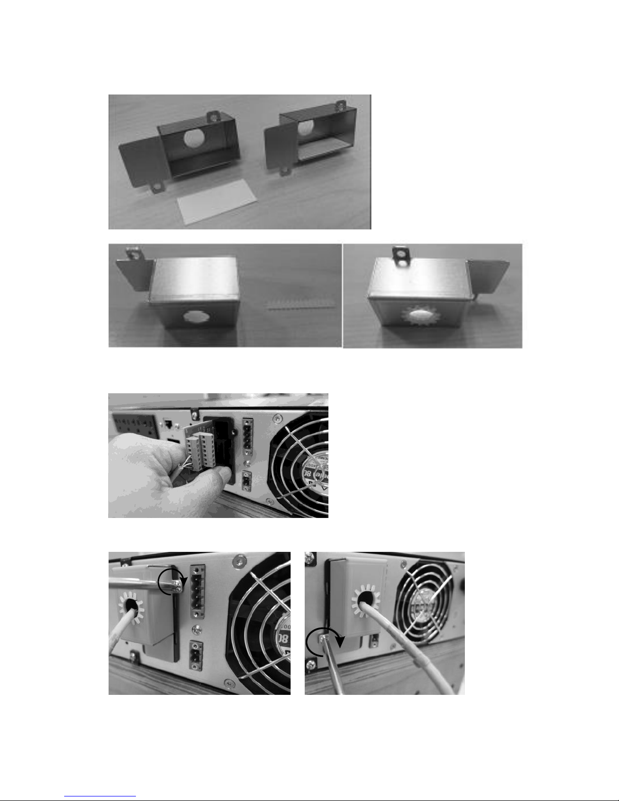
Installation
1. Open the plastic cover of the intelligent slot onto back of UPS as
following picture.
Page 3
2
2. Add isolation label and cable protector as following pictures.
3. Insert the mini AS400 card into the intelligent slot as following picture.
4. Connect the cable, then screw the cover as following pictures.
Page 4
3
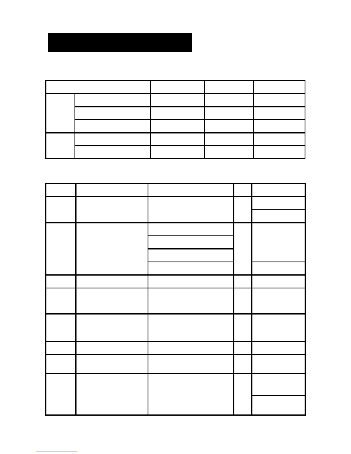
Mini AS400 Specification
Mini AS400 card provides dry contact signal only, below is the parameter
range.
Parameter
SYMBOL
MAX.
UNIT
Diode
Reverse Voltage
VR 6 V
Forward Current
IF
80
mA
Peak Forward Current
IF (peak)
1
A
Relay
DC Voltage
VDC
24
V
DC Current
IDC 1 A
Pin definition.
Pin
Signal definition
Reason
I/O
Jumper location
9
UPS Fault
UPS Internal Fault
Out
NO:JP1 2-1
NC:JP1 2-3
11
Summary Alarm
1. Utility Failure
Out
NO:JP3 2-1
2. UPS Fault
3. Bypass Mode
4. Communication Error
NC:JP3 2-3
1,3,6,10
External power ground
In
12
Remote Shutdown /
UPS Test
Shutdown in battery mode /
UPS Test (3-10S signal length)
In
UPS Test:
JP8 2-1
14
UPS ON(SON)/
UPS OFF(SOFF)
Remote control UPS :
Switch on / Switch off
In
8
Common
In
13
Pin 14,12 ground
2
Bypass Active
Bypass Active
Out
NO:JP5 2-1
NC:JP5 2-3
Page 5

4
4
Battery Low
Battery Low
Out
NO:JP2 2-1
NC:JP2 2-3
5
UPS ON
UPS Output
Out
NC:JP4 2-1
NC:JP4 2-3
7
Utility Failure
Utility Failure
Out
NO:JP6 2-1
NC:JP6 2-3
Connection example
To remote monitor UPS status as example, user can connect the circuit
as following picture.
User need to provide power (below 24VDC) and ground. Connect the
display and control button to the interface to get UPS operation status and
remote shutdown UPS when utility becomes failure.
 Loading...