

Page 1

Cervo 2.4
Cervo 2.4 Pro
OWNER’S MANUAL
Page 2

Saris Cycling Group, Inc.
Model #: Cervo 2.4
IC: 3797A-BKMA
FCC ID: 06RBKM-A
2
Copyright
Copyright 2005. All rights reserved. No part of this publication may be copied, pho-
tographed,reproduced, translated, transmitted electronically or placed on digital
media without the prior written consent of Saris Cycling Group, Inc.
Trademarks
Saris Cycling Group, Inc. Cervo 2.4 and the Cervo 2.4 logo, are all registered trademarks
of Saris Cycling Group, Inc. All other product, brand, or trade names used in this manual may be trademarks or registered trademarks of their respective owners.
Modifications
Saris C
ycling Group, Inc reserves the right to make improvements and/or updates to
the products described herein at any time without notice.
FCC Statement of Compliance:
Statement of Compliance for FCC and Industry Canada:
"This device complies with Industry Canada and Part 15 of the FCC Rules. Operation is subject to
the following two conditions: (1) This device may not cause harmful interference, and (2) this
device must accept any interference received, including interference that may cause undesired
operation."
The term "IC:" before the radio certification number only signifies that Industry Canada technical
specifications were met.
Changes or modifications to this device not expressly approved by the party responsible for
compliance with FCC regulations (the manufac
turer) could void the user's authority to operate
the equipment.
This equipment has been tested and found to comply with the limits for a Class B digital device,
pursuant to part 15 of the FCC Rules. These limits are designed to provide reasonable protection
against harmful interference in a normal installation. This equipment generates, uses and can
radiate radio frequency energy and, if not installed and used in accordance with the instructions,
may cause harmful interference to radio communications. However, there is no guarantee that
interference will not occur in a particular installa
tion
Page 3

About This Manual
3
Thank you for your purchase of the CycleOps Cervo 2.4. The Cervo 2.4 is the ultimate
bicycle computer by providing real-time biometric data and download capabilities.
This manual describes the proper use and maintenance of the CycleOps Cervo 2.4.
Every
person, independent of skill level, should read at least PRECAUSTION: IMPORTANT
prior to use of the Cervo 2.4.
DEFINITIONS
Bold
Letters =Bring special attention to important points and that should be read and
understood prior to using the PowerTap.
Italicized Letters = Indicate reference to another section of the manual where further
explanations are found.
This ma
nual describes the functions of the Cervo 2.4. For the most current owners
manual available please consult
CycleOps at www.cycleops.com.
Page 4

Maintenance & Specifications
Computer Batteries
Technical Specification
Range of Measurement
Test Mode
Glossary
4
Table of Contents
About this Manual
Precautions: Impor tant
System Overview
The Cervo2.4 System
Preparing for Installation
Upgrading to PowerTap
System Installation
General Computer Operation
Display Levels
Buttons
Display Modes
Finding Sensors
Clearing Data
Power
Conservation
Computer Navigation
Heart Rate Function
Speed Function
Multi-Function
Heart Rate Monitor Mode
Interval Mode
Interval Memory Mode
Computer Setup
Computer Setup Main Menu
Computer Setup 1
Computer Setup 2
Computer Setup 3
Computer Setup 4
Computer Setup 5
Page 5

Precautions: Important
• Before beginning any exercise program, consult your physician.
• Keep your eyes on the road. Do not become overly engaged with the Cervo2.4 dis-
play.
•
• We recommend familiarizing yourself with computer functions while stationary,
• Wash off dirt with a cloth soaked in a weak mixture of neutral detergent and water
and wipe excess water off with a dry cloth Avoid spraying the unit directly with sol-
vent mixture.Do not use thinner or other solvents to clean parts as they may dissolve
the plastic console casings.
• Failure to adhere to these precautions may cause premature failure or incorrect
operation of the unit and may void the warranty. Please register your Cervo2.4 at
www.cycleops.com.
5
Page 6

1 Computer
1 Speed Sensor
1 Chest strap
12 Cable ties
1 PowerAgent Software CD
1 Download cable
1 Wheel magnet
1 Cadence Sensor (Cervo 2.4 Pro Only)
1 Instructional DVD
Qty Item
Package Contents
6
System Overview
THE CERVO 2.4 SYSTEM
The Cervo 2.4 system includes a computer and harness which measures speed, dis-
tance, cadence (Pro), and heart rate. Th is information is transmitted via receiver placed
on the front fort. The receiver transfers the data via a wired signal to a
computer
mounted on the handlebar or stem. Heart rate data is transferred via a non-coded
telemetry signal from the chest strap monitor. The data is then integrated to display
current, average, and maximum biometric information.
PREPARING FOR INSTALLATION
The only item needed for installation in a cable cutter to trim excess cable tie. See
TABLE 1 to verify package con
tents..
UPGRADING TO POWERTAP
The Cervo is the same computer used with the PowerTap SL 2.4 models. Some of the
features on the Cervo will not function without the PowerTap hub and receiver. The
Cervo 2.4 can easily be upgraded to the PowerTap SL 2.4 by con
tacting your local
dealer or CycleOps directly at 800-783-7257.
Page 7

SYSTEM INSTALLATION
1. Attach Sensor to Fork
Attach sensor to front fork so the magnet passes
within 3-5 inches of the sensor (FIGURE1). Place
cable tie through sensor to secure. Ma ke sure the
logo side of the sensor faces the magnet.
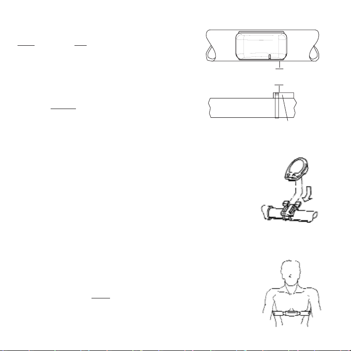
3. Attach Computer Shoe to Handlebar or Stem
The receiver
shoe can be mounted on either the handlebar or stem. Secure the
mounting base with cable ties. Slide the computer shoe in the direction of the arrow
as depicted in either FIGURE 2A or 2B depending on mounting location.
Computer Shoe
Mounting Base
Arrow
Slide shoe in direction of arrow onto the base.
Slide shoe in direction of arrow onto the base.
2A. Attach Receiver mount to Handlebar
2B.Attach Receiver mount to Stem
Computer Shoe
Mounting Base
Arrow
7
SPOKE
FORK
(12.7 MM)
SPOKE MAGNET
1/2”
MAX
SPEED SENSOR
Page 8
4. Install Cadence Sensor (Pro)
Only
the Cervo Pro is able to measure cadence
with the included cadence sensor. First install
the pedal cadence sensor to the left chain stay
in line with the pedal spindle. Next attach
cadence magnet to the crank arm. Ensure the
center of the magnet passes the line
of the sen-
sor unit. Do not
center the magnet in relation to
the
sensor (FIGURE 3). See COMPUTER SETUP 4 to
correctly configure the computer for the chosen
method of cadence determination.
5. Place Computer into Computer Shoe
Place the computer into the mounting shoe
on the handlebar or
stem. Line up the slots on the base of the computer with the
bracket and slide computer toward the rider (FIGURE 4). NOTE:
Ensure the computer is fully inserted onto the receiver shoe for
proper data transmission.
6. Heart Rate Mon
itor Strap
Position the heart rate monitor strap on your torso as pictured in FIGURE 5. The strap should rest just beneath the
pectoralis muscles of the chest. For best results slightly
moisten the electrodes where contact is made with skin.
The heart rate strap must be worn to enable the heart rate
function. NOTE: The chest strap for the Cervo2.4 uses a
coded frequency and is not compatible with other
manufacturer’s chest straps.
FIGURE 3
FIGURE 4
FIGURE 5
8
CRANK ARM
1/2”
(12.7 MM)
MAX
CADENCE MAGNET
CHAINSTAY
Page 9

7. Verify Installation
Check to make sure all components are properly secured.
Spin wheel and verify that in the upper left hand corner of
the computer the transmission icon illuminates (FIGURE 6).
This indicates the sensor is properly transmitting a signal to
the computer. If the transmission icon is not illuminated
consult TROUBLESHOOTING for further instructions.
FIGURE 6
9
Page 10

General Computer Operation
DISPLAY LEVELS
The computer has three (3) main display levels:
Top
• Heart Rate
Middle • Speed
Bottom • Multi-Function Display
NOTE: The current display level is indicated by two
black cursors located on either side of the computer
display. (FIGURE 7)
BUTTONS
There are two (2) buttons on the computer:
1) [Mode]
2) [Select]
NOTE: [BRACKETED] words indicate
buttons.
There are five (5) types of button presses:
1) Press [MODE] or [SELECT]
= a single press and release of either [MODE] or
[SELECT].
2) Hold [MODE] or [SELECT]
= a single button press and hold of either
[MODE] or [SELECT] for 2 sec.
3) Press [MODE] and [SELECT]
= simultaneously press and release of both
[MODE] and [SELECT].
144
25
58.I0
3
D
2.4
INTERVAL
DISPLAY
MODE (LEFT)
CURRENT HEART
RATE
SPEED
DISPLAY
MULTI
DISPLAY
BOTH
SELECT
Changes active
mode
Clear data
Enter setup
Find
Select function
3
10
Page 11

SCROLLING MENU:
Find: If [MODE] and [SELECT] are released
When “Find” is displayed the computer will find
Search for the PowerTap hub.
clr: If [MODE] and [SELECT] are released when
clr is displayed ALL DATA WILL BE ERASED.
SEt: If [MODE] and [SELECT] are released
When S
Et is displayed on the top level of the
Screen, a flashing “E”, d and t on the middle
Level and 12345 on the bottom level.
E= exit, return to ride mode
d= restore default settings
T= test mode
1 2 3 4 5 = setup menus
11
4) Hold [MODE] and [SELECT] = simultaneously press and hold both [MODE]
and [SELECT] for 2 sec. NOTE : Continuing to hold longer than 2 sec. will clear
all data.
5) Extended Hold [MODE] and [SELECT]
= simultaneously press and hold of
both [MODE] and [SELECT] for greater than 5 sec.
DISPLAY MODES
The computer has two (2) main modes of operation:
1) Trip
2) Interval
Hold [MODE] to toggle between display modes.
POWER CONSERVATION
The computer has power saving features to prolong battery life. The computer powers
down the display after four (4) minutes of inactivity. Pr
ess either [MODE] or [SELECT]
to activate the display.
Page 12

Computer Navigation
HEART RATE FUNCTION
The top level of the main display shows current, and average heart rate readings.
1) Press [MODE] to scroll the cursor to the top line of the main display.
2) Press [SELECT] to toggle through the heart rate function options.
Current Heart Rate
Current heart rate is displayed on the top line and shown up to 255
beats per minute (BPM) (FIGURE 8). You must wear the heart rate chest
strap to enable the heart rate measurement function. NOTE : The
Cervo2.4 uses a non-coded chest strap.
Averag
e Heart Rate
This value is a running average of the heart rate in BPM. If there is no
heart rate information a “0” will display (FIGURE 9).
SPEED FUNCTION
The middle level of the main display shows current, max, and average speed readings.
1) Press [MODE] to scroll the cursor to the middle line of the main display.
165
25
2584
165
25
2584
3
MI
3
MI
AV
O
O
FIGURE 8
FIGURE 9
12
Page 13

2) Press [SELECT] to toggle through the speed function options.
Current Speed
Speed is displayed in either miles per hour (MI) or kilometers per hour
(KM) up to 99.9 mi/hr or km/hr in 0.1 mi/hr or km/hr increments. Current
speed readings are displayed when only “MI” or “KM” appears below the
middle line. (FIGURE 10)
Maximum Speed
Either “MI” or “KM” and “MX” displayed simultaneously indicate the highest recorded speed since the last time data was cleared in trip mode or
the selected interval in interval mode. (FIGURE 11)
Average Speed
Either “MI” or “KM” and “AVG” displayed simultaneously indicate the average recorded speed since the last time data was cleared in trip mode or
the selected interval in interval mode. (FIGURE 12)
MULTI-FUNCTION DISPLAY
Distance (D)
Total trip or the selected in
terval distance in interval mode is displayed in miles or
kilometers from 0.00 to 999.99 (FIGURE 13).
1) Press [MODE] to scroll the cursor to the bottom line of the main display.
165
25
58.I0
3
MI
D
165
33
58.I0
7
MX MI
D
165
20
58.I0
3
AV MI
D
FIGURE 10
FIGURE 11
FIGURE 12
13
Page 14

2) Press [SELECT] to toggle through the multi-function displays until the
“D” icon is displayed.
NOTE: Distance is displayed in the same units as speed.
Trip Time and Time of Day (T)
Total trip time, interval time, and time of day is displayed to 9:59:59 (FIGURE 14).
1) Press [MODE] to scroll the
cursor to the bottom line of the main dis-
play.
2) Press [SELECT] to toggle through the multi-function displays until the
“T” icon is displayed.
3) While in trip time hold [SLECET] to access the real time clock.
4) Hold [SELECT] to return to trip or interval time.
NOTE: Auto start and stop with rotation of the wheel i
s the default set-
ting. To customize auto start and stop see COMPUTER STETUP 4.
Cadence (C)
Only
the Cervo2.4 Pro is able to measure cadence with the included cadence sensor.
The rate of pedaling is shown from 20 to 240 RPM.
1) Press [MODE] to scroll the cursor to the bottom line of the main display.
165
25
58.I0
3
MI
D
165
25
2.5 I.43
3
MI
T
165
25
07:16
3
MI
T
FIGURE 13
FIGURE 14
14
Page 15

2) Press [SELECT] to toggle through the multi-function displays
until the “C” icon is displayed. (FIGURE 15)
Average Cadence (C & AVG)
Only
the Cervo2.4 Pro is able to measure cadence with the included
cadence wire package. The average cadence displays data since the last
time data was cleared in trip mode or the selected interval in interval
mode. Average cadence is display
ed in RPM.
1) Press [MODE] to scroll the cursor to the bottom line of the main display.
2) Press [SELECT] to toggle through the multi-function displays until
the “C” and “AVG” is displayed. (FIGURE 16)
Energy Expenditure (E) (POWERTAP ONLY)
The total work done over the course of the trip or interval i
s shown in kilojoules. This
value is a measure of the total energy expended over the course of your ride. Thi s is
roughly equivalent to dietary calories expended.
1) Press [MODE] to scroll the cursor to the bottom line of the main display.
2) Press [SELECT] to toggle through the multi-function
displays until the
“E” is displayed. (FIGURE 17)
15
365
25
89
WATTS
3
MI
C
365
25
76
WATTS
3
MI
C AV
365
25
2009
WATTS
3
MI
E
FIGURE 15
FIGURE 16
FIGURE 17
Page 16

Odometer (O)
Total accumulated distance traveled since the last system reset is
displayed in miles or kilometers. To manually input the your odometer
reading see COMPUTER SETUP 1.
1) Press [MODE] to scroll the cursor to the bottom line of the
main display.
2) Press [SELE
CT] to toggle through the multi-function displays until
the “O” is displayed. (FIGURE 18)
165
25
2584
3
MI
O
FIGURE 18
16
Page 17

INTERVAL MODE
The computer has two display modes. The trip mode shows total
trip metrics, and the interval mode displays interval specific infor-
mation. The interval mode functions as a lap marker and is essen-
tially always on.
To b egin the first interval, or advance to the next interval:
Press and release
[MODE] and [SELECT] simultaneously. NOTE: Do
not hold both buttons down as you will clear all data from the
computer.
In trip mode “INT” and the new interval number will appear and disappear (FIGURE
19). The computer can mark an unlimited number of intervals although after nine (9)
the marker will begin to count back at one (1). For example, interval ten (10) is dis-
played following interval (9) as one (1).
To v iew interval specific data (power, speed, an
d multi-function display) from any loca-
tion on the display:
1) Hold [MODE] until “INT” appears on the left hand side of the display. The “INT” and
interval number will remain illumined as a forth line in the main display (FIGURE 19).
The data displayed is that of the current interval number shown.
2)To exit bac
k out of interval mode hold [MODE] until “INT” disappears.
heart rate
speed
int
multi
17
Page 18

INTERVAL MEMORY MODE
To a ccess stored interval data for the previous 9 intervals only
:
1) Enter the interval mode hold [MODE] until “INT” appears on the left hand side of the
display.
2) Press [MODE] to scroll until the “INT” flashes. NOTE: INT now constitutes a fourth
level of display.
3) Hold [SELECT] and the memory icon (”M”) appears next to the interval number
(FIGURE 20).
4) With “INT” fla
shing, press [SELECT] to advance to the interval you wish to view.
5) Press [MODE] scroll the cursor to the line of information you wish to view. NOTE:
Recovery periods as well as work periods are displayed in memory mode.
To exit back out of the interval memory mode hold [SELECT]
until th
e memory icon disappears. The computer is now displayed in the interval mode. To exit from the interval mode
from any location on the display hold [MODE] until “INT” dis-
appears.
heart rate
speed
int m
multi
18
Page 19

Computer Setup
The setup feature has four (4) main modes. You do not have to complete all four to
change settings. Please reference each mode to determine the correct location to
begin. NOTE: The computer illustrations for each mode display the factory default set-
tings.
COMPUTER SETUP
MAIN MENU
1) Press either [MODE] or [SELECT] to activate the computer.
NOTE: The version of firmware is displayed upon startup. The
most updated firmware version is available at www.cycleops.com.
(FIGURE 21)
2) Extended hold of [MODE] and [SELECT] simultaneously enters
c
omputer setup function as indicated by a flashing “E”. NOTE:
Continue to hold through
“clear all” screen. Releasing hold early
will clear all current data.
3) The setup mode displays three (3) letters and numbers 1-4.
Each letter represents a setup menu. A flashing alphanumeric
character indicated current selectio
n. (FIGURE 22)
E = exit, return to ride mode
d = restore default settings
T = test mode
1 2 3 4 5= setup menus
4) Press [SELECT] to scroll to the desired setup mode.
5) Press [MODE] to begin setup.
PR
2.00
Set
E
1234
t
d
Setup Menu
19
Page 20

Std
t
1
Std
t
p
Std
p
t
12:0
20
COMPUTER SETUP 1
This setup menu includes: tim e of day, date, storage rate, wheel circumference, units
of measure, odometer. NOTE: You are unable to move back to a previously viewed set-
tings. You must restart setup 1 to make corrections.
1) From the computer setup main menu press [SELECT] and scroll
until the number one (1) is flashing. Press [MODE] to enter setup
mode.
2) Press [SELECT] to toggle between a 12 or 24 hour clock. Press
[MODE] to save.
3) Press [SELECT] to toggle between AM (A) or PM (P). Press
[MODE] to save
.
4) Press [SELECT] to toggle through digit values to set hours in
time of day. Press [MODE] to save.
Page 21

Std
03
01-
c
Year
Day
Month
Std
rec
1
Recording Settings
(seconds)
1 2
Max. Recording Time
(hrs)
15 30
21
5) Press [SELECT] to toggle through digit values to set minutes in
time of day. Press [MODE] to save.
6) Press [SELECT] to toggle through digit values to set year, month,
and date. Press [MODE] to save.
7) Press [SELECT] to toggle through storage rate values (1, 2
seconds). Press [MODE] to save. NOTE: Diff
erent storage rates yield
different amounts of total storage time. Changes to the storage
rate does not
effect display information. Refer to TABLE 3 for
appropriate storage rate.
TABL E 3 - Cervo2.4 Storage Rate
Page 22

24 x1.0
26 x1.0
26 x1.25
26 x1.5
26 x 2.0
26 x 2.125
27 x1.0
27 x1.125
1753
1913
1953
1986
2055
2070
2125
2139
27 x 1.25
700C tubular
700 x 20C
700 x 23C
700 x 25C
700 x 28C
700 x 32C
700 x 38C
2152
2094
2084
2096
2108
2116
2136
2170
Wheel Circumferences
Tire Size Circ.(mm) Tire Size Circ.(mm)
Std
1
CI
2096
Std
1
MI
22
8) Press [SELECT] to toggle through digit values to set the wheel
circumference. Press [MODE] to save. Refer to TABLE 4 for common
tire information. NOTE: For the most accurate reading perform a
roll out measurement (mm) of the rear wheel.
TABLE 4 - Common Wheel Circumferences
9) Press [SELECT] to
select English or Metric units. Press [MODE] to
save.
Page 23

Std
1
00000
OD
23
10) Press [SELECT] to set starting odometer reading. Press [MODE]
to save. NOTE: Odometer settings are saved during battery
changes.
Page 24

COMPUTER SETUP 2
This setup menu includes: rat e of display for watts, speed, cadence, and heart rate.
NOTE: You are unable to move back to a previously viewed settings. You must restart
setup 2 to make corrections. NOTE: These settings do not
effect the data stored for
download.
This function can be used to allow better pacing during time trial efforts. A greater
rate of display allows for a slower update of the display.
1) From the computer setup main menu press [SELECT] and scroll
until the number two (2) is flashi
ng and press [MODE] to enter
setup mode.
2) Press [SELECT] to toggle through (1, 2, 3, 5 10, 30) rate of display
values in seconds for watts. Press [MODE] to save. Thi s setting only
applies when a PowerTap hub is installed.
3) Press [SELECT] to toggle between (1, 2, 3, 5 10, 30) rate of display
values in seconds for speed. Press [MODE] to save.
4) Press [SELECT] to toggle between (1, 2, 3, 5 10, 30) rate of display
values in second
s for cadence. Press [MODE] to save. Thi s setting
only applies to the Cervo2.4 Pro model.
Std
1
00000
OD
PR
2
3
AV MI
PR
2
5
C AV
POWERTAP Only
24
Page 25

PR
3
0
s
YES
AV WATTS
POWERTAP Only
PR
0
s
AV MI
YES
PR
3
0
s
YES
PR
3
t
YES
POWERTAP Only
25
COMPUTER SETUP 3
This setup menu includes: zero readings for power, speed, and cadence. NOTE: You
are unable to move back to a previously viewed setting. You must restart setup 3 to
make corrections. NOTE: These settings are useful for determini
ng you average when
pedaling only and do not
effect the data that is stored for download.
1) Press [SELECT] to toggle between yes and no for zeros included
in average of watts. Press [MODE] to save. Thi s setting only applies
when a PowerTap hub is installed.
2) Press [SELECT] to toggle between yes and no for zeros included
in average of speed. Press [MODE] to save.
3) Press [SELECT] to toggle between yes and no for zeros included
in average of cad
ence. Press [MODE] to save. Thi s setting only
applies to the Cervo2.4 Pro model.
4) Press [SELECT] to toggle between yes and no for auto-zero func-
tion. Normally
leave at yes. NOTE: A uto -zero is used for track bike
use where large negative torque may be present. Hub modifica-
tion to fixed hear is necessary. This setting only
applies when a
PowerTap hub is installed.
Page 26

PR
4
4
SLEE
PR
4
mi
PR
4
pedal
c
Hu
P
POWERTAP Only
PR
4
mi
watts
POWERTAP Only
26
COMPUTER SETUP 4
This setup menu includes: sleep time, locations of display, cadence source, cycle computer mode, heart rate monitor, and auto start/stop. You are unable to move back to a
previously viewed settings. You must restart setup 4 to mak
e corrections.
1) Press [SELECT] to set how many minutes the computer will stay
“awake” af t er not receiving a valid speed or heart rate signal. Press
[MODE] to save. NOTE: The shorter the sleep time the better the
battery life.
2) Press [SELECT] to det
ermine what is displayed in the middle line.
(mi = speed, c = cadence, () = heart rate). Press [MODE] to save.
The selected metric will flash during the ride.
3) Press [SELECT] to determine cadence information source.
Default = pedal then hub
Pedal = c
rank only
Hub = hub only
Press [MODE] to save.
This setting only
applies when a PowerTap hub is installed.
4) The Cervo2.4 can be used as a cycle computer or heart rate
monitor. Press [SELECT] to toggle through mode options.
watts, mi, and ( ) = power meter mode
mi, and ( ) = cycle computer mode
( ) = heart rate monitor mode
Press
[MODE] to save.
This setting only applies when a PowerTap hub is installed.
Page 27

PR
4
mi
watts
data
hub
Id
45847
hub
Id
LEArn
1
27
5) Press [SELECT] to toggle through auto start options.
mi, and data = allows trip time to count when wheel speed is regis-
tering. Trip time stops 3sec. af ter if speed is not registered.
( ), and data = allows trip time to count as long as a heart rate sig-
nal is
registered. This function is useful in the transition from
cycling to running and vice versa.
Press [MODE] to save.
COMPUTER SETUP 5
This setup allows the CPU to learn a new device or sensor such as the hub, heart rate strap and
optional cadence sensor. NOTE: This process only needs to be used if a new sensor or hub is
being used in conjunction with your CPU or vice versa and if batteries are changed in the hub or
chest strap. There are 2 Learn sequences, 1 and 2. Learn 1 is used when you have switched sensors or the CPU and there are no other like bikes with PowerTap SL2.4 within a 30’ radius. Learn 2
is used if there are other devices in the area but requires you to remove and reinsert the battery
before activating the Learn 2 sequence.
1) To manually change the hub I.D. Push [Select] to toggle through the
Hub I.D. Press [Mode] to save.
2) In most ca
ses the Hub I.D. will not be known so you can "learn" the I.D. by
pressing [Mode] to advance through the Hub I.D. settings to Learn 1. NOTE:
Learn 1 will search for any active hub so be sure that there are no other
active hubs in the area. If there are, proceed to Lear
n 2.
Page 28

28
hub
Id
LEArn
1
flashing
hub
Id
LEArn
2
hub
Id
LEArn
2
flashing
3) Learn 1 is initiated by Holding [Select] until "Learn" begins flashing.
When the CPU has learned the device I.D. it will display the I.D.
Press [Mode] to advance to the next device I.D. If it did not learn the device
it will take you back to the most recent Hub I.D. NOTE: Make sure the hub is
"awake" by spinning the wheel or axle.
4) Press [Mode] until Learn 2 is displayed. Learn 2 is used when there are
other "awake" or active PowerTap SL 2.4 hubs within a 30 foot radius.
5) Initiate Learn 2 by first removing the batteries from the hub for 5
seconds
and replacing them. Then hold [Select] until "Learn" begins to
flash. When the CPU has learned the hub I.D. it will display the I.D.
Press [Mode] to save and proceed to the next device I.D. If it did not learn
the device it will take you back to the most recent Hub I.D.
6) Follow the above ste
ps for any additional sensors you may be using,
such as the heart rate strap, speed and cadence sensors.
SPd = speed sensor
Cd = cadence sensor
HS = heart rate sensor
Page 29

Maintenance & Specifications
COMPUTER BATTERIES
The Cervo2.4 computer batteries typically need to be
changed every 400 hours of use. The computer will says “low
bat” when the computer battery needs to be changed. This
message is displayed after a “clr” is performed. To replace
comput
er battery (Type CR2032), remove the computer from
the mount. Remove the battery cover on the back of the
computer (use a cone wrench to remove the battery cover),
exchange the battery, and replace the cover as shown below
(FIGURE 23).
TECHNICAL SPECIFICATIONS
Interval Data Storage Unlimited
Interval Display 9 Intervals (internal recording)
Operational Temperature 0 to 40 degrees c or 32 to 104 f
Battery Life (Computer) 400 hours approx.
RANGE OF MEASUREMENT
Speed 2-59 mph (3-95 KPH)
Distance 0.00 to 9999.99 (Miles)
Trip Time 0.00.00-999.99 Minutes
Cadence 40-140 RPM
Total energy 0-99999 Kilojoules
Odometer 0-99999 Miles or Kilometers
Heart Rate 0-255 BPM (Beats per Minute)
29
Page 30

TEST MODE
1) From the computer setup main menu press [SELECT] and scroll until the letter “t” is
flashing. Press [MODE] to enter setup mode.
2) Press [MODE] to scroll through the different test modes as shown by the number.
NOTE: Press and hold [MODE] and [SELECT] simultaneously returns to standard
operation.
0 - Model and version.
Displays the model on the middle line and version number o
n the bottom line.
1 - LCD Test
Press [SELECT] all the LCD segments are displayed. Press [SELECT] to return to the
normal screen.
2 - Receiver Test Signal
NOTE: The transmission icon is illuminated.
The middle line display flashes “88” with eac
h blip of data from the receiver whether
valid or not.
3 - Heart Rate Signal Test
NOTE: The heart rate signal is illuminated.
The middle line display flashes “88” with each heart rate blip received.
4 - Bike Computer Wheel Magnet Detect
NOTE: The “mi” or “KM” icons are illumined.
The middle line
display flashes “88” with each sensing of the wheel magnet next to
the receiver.
30
Page 31

5 - Cadence Test
NOTE: The C icon is displayed
The top line display shows crank cadence sensor RPM. The middle line flashes “88”
with each pulse from cadence sensor. The bottom display shows cadence RPM value
from the hub.
6- Torque Information
NOTE: The T icon is displayed.
This displays information about the internal workings of the torque readings. The bot-
tom display is the offset torque value directly sent by the hub torque with no correc-
tion applied. The hub sends a value of approximately 512 as the zero point. The middle
line display is
the correction offset value currently stored in the computer. Th is is the
value that is changed when you do a manual zeroing of the torque. Th e top display is
the corrected actual torque (the bottom value minus the
middle value).
7 - Standard Test File
This mode
writes a small test file to the memory. Press [SELECT] and the bottom lines
says "run" and then "yes" when the file is written. This file can then be downloaded.
8 - Communication Loop Back Test
When looking at the front side of the computer, use a c
oin or paper clip to short out
the two pins on the left side. Press [SELECT]. The bottom line will say "run" and then
"yes" if it passes the test correctly. If the pins are not shorted together or there was a
problem, the display will say "no". This test can be r
epeated by pressing [SELECT].
9 - Fast Memory Test
This tests the memory in the computer. Press [SELECT] and "run" is displayed on the
bottom line. Wh en the test is completed and it passes, it says "yes". If the test should
fail, the bottom line will
say "no".
31
Page 32

Glossary
Computer - Refers to the yellow handlebar or stem mounted device.
Heart Rate (HR) - This displays current HR. Max and average values are displayed if
[MAX] or [AVG] is selected. NOTE: A non-coded chest strap must be used in orde
r for
the console to pick up heart rate.
Cadence (C) - The number of pedal revolutions per minute. The rate of pedaling is
shown from 0 to 140 RPM.
Speed - The estimated speed that you would be traveling on a flat road with no wind
is displayed here.
Scroll - to move verti
cally through available menu or screen options
Toggle - to move horizontally through alphanumeric digits
Cursor - the ® arrow located on console screen
Metrics - a standard of measurement
MAX - Max
RPM - Revolutions Per Minute
MI - Miles Per Hour
KM - Kilometers Per Hour
UI - User Int
erface
32
16971 11/06 Saris Cycling Group, Inc. 5253 Verona Road Madison Wi 53711 800.783.7257
 Loading...