

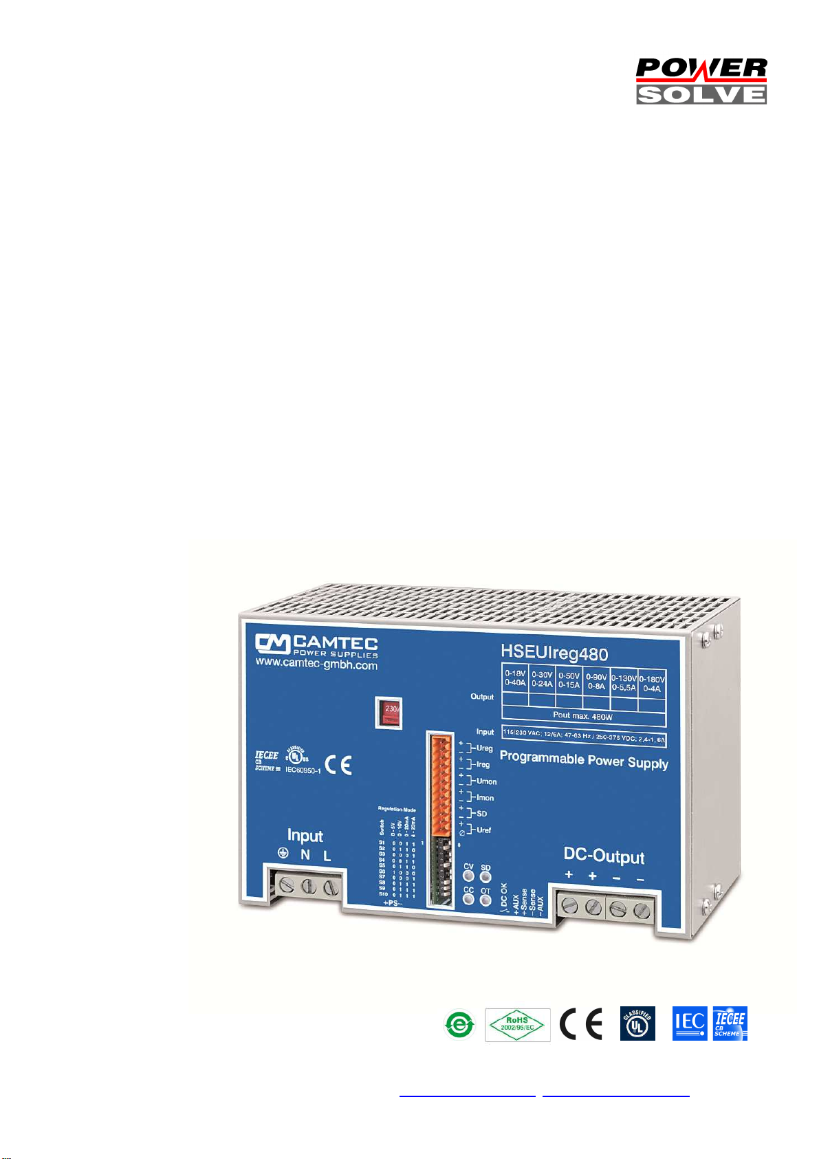
HSEUIreg04801 DIN Rail
Made in Germany
480W Programmable Power Supply
current and voltage programmable
Specification:
• Metal housing
• 90% efficiency
• -25°C...+60°C full output power
• Natural convection
• Galvanic insulated
• Continuous short circuit protected
• Overload (OVP) & low voltage protected
• Soft start & auto-recovery
• Hold up time >50ms
• No base load required
• Electronic inrush current limiter 13.8Apeak
Available outputs: 0…18V, 0…30V, 0…50V, 0...90V, 0...130V, 0...180V, 0...240V
Powersolve Electronics Ltd., Unit 8A Arnhem Road, Newbury RG14 5RU, United Kingdom
Tel 0044 (0)1635 521858 Fax 0044 (0)1635 523771
(Subject to alterations. This product is not designed to be used in applications such as life support systems wherein a failure or malfunction could result in injury or death)
• Analogue interface 0-5Vdc/0-10Vdc/0-20mA/4-20mA
• Real time output monitoring of voltage and current
• External shutdown
• Sense control
• Series & parallel operation
• DIN Rail 35mm & wall mount
• Screw terminals AWG20...AWG6
• High reliability, shock & vibration proof
• 24 hours burn in test
• EMI/EMS EN61000-6-2,3, EN55022 class B
• IEC(EN)60950-1 in accordance to cUL60950/16950
In accordance with IEC60950-1
www.powersolve.co.uk sales@powersolve.co.uk
p.1/9 05.12D

AC
Input 90..132Vac / 184..265Vac , 47…63Hz , 250…375Vdc
AC Input Rating
115Vac<8.8A 230Vac<4.3A 250Vdc<2.4A 375Vdc<1.6A
Rated DC Voltage
0...18V
0...30V
0...50V
0...90V
0...130V
0...180V
0...240V
Overvoltage Protection
22Vdc
35Vdc
59Vdc
105Vdc
150Vdc
210Vdc
280Vdc
Max. DC Current
-
25°C...+60°C
0...40A
0...24A
0...15A
0...8A
0...5,5A
0...4A
0...3A
Max. DC Current +70°C
0...30A
0...18A
0...11,3A
0...6A
0...4,1A
0...3A
0...2,3A
Ripple Peak 230Vac 20MHz
40mVpp
40mVpp
100mVpp
150mVpp
200mVpp
300mVpp
400mVpp
Pmax
480W continuous
Operation Failure Relay
Yes, break contact (fig.4), protective electrical separation
≤60Vdc
Sense Function
Compensation 2V per lead load, protective electrical separation
≤60Vdc
Remote Shutdown
Yes, protective electrical
separation
≤60Vdc
Analogue Interface
Yes, protective electrical separation
≤60Vdc
Digital Interface
Yes, available option (incl. Software), protective electrical separation
≤400Vdc (t.b.a.)
Derating
+60°C...+70°C 2.5%/°C
Accurancy
< ± 1.5% interface
Load Regulation
< ± 0.05% 0
-
100%
Slew Rate
15ms rise time 0V
...
Umax
Response Load Change
<1ms 10
-
100%, 100
-
10%
Base Load
None
Efficiency 230Vac
90% typical
Short Circuit Protection
Continuous
Idling
-
proof
Yes, continuous
Temperature Control
Yes,
thermal shutdown with auto recovery (+70°C, metering distance 10mm)
Hold Up Time
>50ms 230Vac
Inrush Current
<9,8Aeff < 13.8Apeak (230Vac) active inrush current limiter
Softstart
100ms typical
Cooling
Natural convection
Ambient Operating Temp.
-
25°C…+70°C
Ambient Storage Temp.
-
40°C…+85°C
Environment
Humidity 95% non
-
condensing @ 25°C,
climate
class. 3k3, pollution rate II
EMI EN55022 class B
EMS EN61000
-6-
2,3
Safety
cUL60950, EN60950
-1
Safety class 1(A)
VDE0805, VDE0100
Isolation Path
> 8mm
Input / Output
Galvanic insulated 3000Vac
Meantime By Failure (MTBF)
400000h (IEC61709)
Dimensions (HxWxD)
130x200x114,5mm
Weight
2900g
Screw Terminals (In/Out)
AWG20...AWG6 , 0,5...16mm²
work.resist.Ω
Progamme [V]
0...10Vdc
1 MΩ
Progamme
[V] 0...5Vdc
1 MΩ
Progamme [A]
0...20mA
500 Ω
Progamme [A]
4...20mA
500 Ω
Monitoring [V]
0...10Vdc/5mA
Monitoring [V]
0...5Vdc/5mA
Shutdown
Open Collect.
Sensing
2V
Reference [V]
10Vdc/5mA
Reference [V]
5,2Vdc/5mA
Power Good
Relay
“b” contact
per lead load
Powersolve Electronics Ltd., Unit 8A Arnhem Road, Newbury RG14 5RU, United Kingdom
Tel 0044 (0)1635 521858 Fax 0044 (0)1635 523771
(Subject to alterations. This product is not designed to be used in applications such as life support systems wherein a failure or malfunction could result in injury or death)
www.powersolve.co.uk sales@powersolve.co.uk
p.2/9 05.12D
Ordering Information:
to the control inputs. Be aware that your PLC is capable to
Output Type (DIN-Rail standard) Part Number Built-in 5W Power Sink Part Number Option Part Number
0...18V HSEUIreg04801.18T 304.1083.001CA HSEUIreg04801.18TPS 304.1083.011CA USB 2.0 Interface
0...30V HSEUIreg04801.30T 304.1083.002CA HSEUIreg04801.30TPS 304.1083.012CA
0...50V HSEUIreg04801.50T 304.1083.003CA HSEUIreg04801.50TPS 304.1083.013CA ADTW201
0...90V HSEUIreg04801.90T 304.1083.004CA HSEUIreg04801.90TPS 304.1083.014CA
0...130V HSEUIreg04801.130T 304.1083.005CA HSEUIreg04801.130TPS 304.1083.015CA PS200 External
0...180V HSEUIreg04801.180T 304.1083.006CA HSEUIreg04801.180TPS 304.1083.016CA
0...240V HSEUIreg04801.240T 304.1083.007CA HSEUIreg04801.240TPS 304.1083.017CA Wall Mount Kit 220.1002.001CA
Conception
The HSEUIreg power supply series realizes very high power efficiency in a
space-saving housing. Latest generation electrical devices relate to the high
reliability of all CAMTEC products. The CAMTEC philosophy is, to employ
125°C low ESR ultra long life capacitors where expedient to achieve a
superior lifetime of our products. The HSEUIreg-series is made for
Measuring & Control-Units to allow an easy design of P- or PI-controllers at
an attractive price value.
Thermal shutdown (p.6 fig.3)
The HSEUIreg-series is featured with a thermal overload shut down and
auto recovery behaviour.
Control type
The power supplies accurately works down low output voltages down to 0V.
Thereby the switching frequency is absolute stabile.
The output response is linear to the input signal.
Sensing feature (p.5)
The HSEUIreg has a sense operation mode to compensate potential drop at
the supply line. It is a standard for the 0..18Vdc, 0..30Vdc and 0..50Vdc
types. For all other types it is a feature up on request.
Shutdown feature
All HSEUIreg units are featured with a shut down (open collector). ON=
open contact, OFF= closed contact 1Vdc max. . The shutdown connections
have an internal pull-up resistor with 6800 Ω at the plus line (+15V inserted).
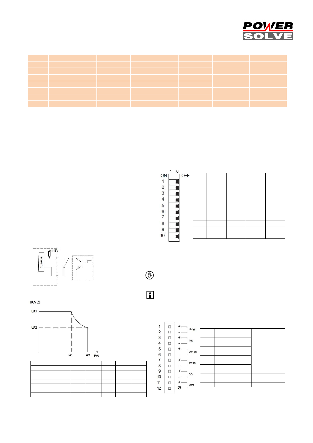
UI-characteristic:
Programmable Outputs:
Output Voltage & output current control:
The output voltage is linear proportional to the input signal.
10% input signal will deliver 10% of the maximum output voltage, 50% input
will give a ratio of 50% output and 100% will provide 100% output. The
USEUIreg features 0-5Vdc, 0-10Vdc, 0-20mA or 4-20mA control signal input.
The setting has to be chosen from a DIP-switch at the front-side. The input
impedance is 1MΩ with voltage control mode settings. The input impedance
is 500Ω with current control mode settings.
Tolerance compensation adjust:
It is not necessary to adjust the basic of the output voltage or output current
level. The engineers abandoned a compensation potentiometer to prevent
malfunction from wrong basic adjustments.
Warning:
Tuning the output voltage over the maximum level may cause deviations
from the technical data table. If the control inputs are not connected at all
this may cause a minimum voltage of 100mV at the device main outputs.
All control I/O are connected to Uref
The current operation mode features a 500R input impedance
trigger recommended line power.
Pos. 0 - 5V 0 - 10V 0 - 20mA 4 - 20mA
S01 0 0 1 1
S02 0 1 1 0
S03 0 0 0 1
S04 0 0 1 1
S05 0 1 1 0
S06 1 0 0 0
S07 0 0 0 1
S08 0 1 1 1
S09 0 1 1 1
S10 0 1 1 1
UI.Drive Software
XP/W7/W8
DC-repeater
200W Power Sink
304.1098.001CA
304.1090.001CA
304.xxxx.001CA
Type UA1 IA1 UA2 IA2 Pmax
HSEUIreg04801.18 18V 26.7A 12V 40.0A 480W
HSEUIreg04801.30 30V 16.0A 20V 24.0A 480W
HSEUIreg04801.50 50V 9.6A 32V 15.0A 480W
HSEUIreg04801.90 90V 5.3A 60V 8.0A 480W
HSEUIreg04801.130 130V 3.7A 87V 5.5A 480W
HSEUIreg04801.180 180V 2.7A 120V 4.0A 480W
HSEUIreg04801.240 240V 2.0A 160V 3.0A 480W
PIN Description Value
01 + V progr. input 0-5V 0-10V
02 - V progr. input
03 + A progr. input 0-5V 0-10V
04 - A progr. input
05 + V progr. output 0-5V/0-10V 5mA
06 - V progr. output
07 + A progr. output 0-5V/0-10V 5mA
08 + A progr. output
09 + SD shutdown Open collector
10 - SD shutdown Open collector
11 + Uref 5.2V /10V 5mA
12 - Uref ref return
0-20mA 4-20mA
0-20mA 4-20mA
Powersolve Electronics Ltd., Unit 8A Arnhem Road, Newbury RG14 5RU, United Kingdom
Tel 0044 (0)1635 521858 Fax 0044 (0)1635 523771
(Subject to alterations. This product is not designed to be used in applications such as life support systems wherein a failure or malfunction could result in injury or death)
www.powersolve.co.uk sales@powersolve.co.uk
p.3/9 05.12D
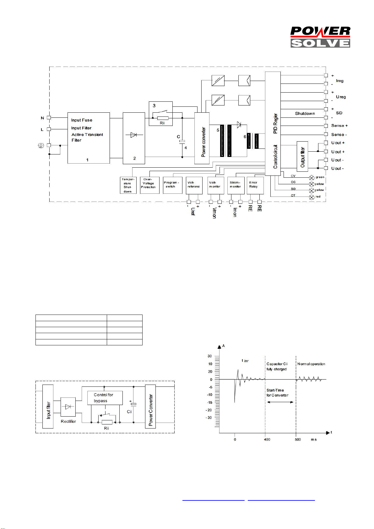
1) Active Transient Filter 2) Rectifier 3) Inrush Current Limiter 4) Load Capacitor 5) Power Transformer 6) Storage Choke
Lighting: CV = constant voltage operation CC = constant current operation SD = shutdown operation OT = temperature failure >70°C
Technical Description
The HSEUIreg-Series is a programmable switch mode power supply. Engineered and manufactured in by CAMTEC in Germany, it is
designed for challenging applications like railway, drives, test-stands and machine-building. The HSEUIreg provides a low Ripple-Noise, good
Load- Regulation and high efficiency >90% (typ. @ 230Vac). High-end long life capacitors guarantee Hold-up-Time and extended lifetime of
the power supply. Our HSEUIreg-design starts complex loads easily. The internal control manages illegal operating conditions to prevent your
system from failures. An operation failures recording is on board via galvanic insulated relay connection (page 2 table). All HSEUIreg power
supplies are idling-proof and short circuit protected. Supply units of the same type and output voltage feature parallel or series operation.
The HSEUIreg also features active high input transients with suppressor diodes, X2-capacitors and varistors. The design rules set value on
extended interference immunity and safety. The PSU is engineered in accordance to EN60950-1 and EMC-compatibility to EN55022 class B.
Indicator 230Vac
Peak inrush current 13.8A peak
Effektive inrush current
Inrush duration (tinr) 400ms
Over all power-up time 500ms
Inrush Current Limiter Block Diagram
Powersolve Electronics Ltd., Unit 8A Arnhem Road, Newbury RG14 5RU, United Kingdom
Tel 0044 (0)1635 521858 Fax 0044 (0)1635 523771
(Subject to alterations. This product is not designed to be used in applications such as life support systems wherein a failure or malfunction could result in injury or death)
(RMS)
9.8Aeff
www.powersolve.co.uk sales@powersolve.co.uk
p.4/9 05.12D

Monitor Outputs SCM (fig.1) Monitor Output Connections (fig.2)
Monitor O
utputs
Program Inputs SCM (fig.3) Program Input Connections (fig.4)
(example with external poti)
Local Sensing (fig.5) Remote Sensing (fig.6)
Battery Charger Mode (fig.7) External Sense Protection (fig.8)
Maximum Sense Compensation (fig.9)
The monitor outputs are buffered with OP-amplifiers, preresistors & parallel connected zener diodes (fig.1). The
monitor outs can be selected between +5Vdc or +10Vdc
control voltage. The signal is absolute proportional to the
adjusted output voltage and current. The monitor outputs
are non-floating. Connections see figure 2.
Programmable Inputs
The output voltage and the output current are
programmed with an analogue signal. The input signal is
selectable between 0-5Vdc, 0-10Vdc, 0-20mA or 4-20mA
with a front sided DIP-switcher. The response is very
exact and. The output response behaves linear to the
control signal.
The inputs are protected with internal pre-resistors,
zener diodes and capacitors (fig.3). The capacitor limits
the slew rate, accurately. The program inputs are nonfloating. The monitor GND is connected to the negative
pole of the main outputs. An incorrect connection triggers
an internal PTC fuse. Unlocking the incorrect connection
resets this fuse to being recovered (auto recovery).
External potentiometer control mode (fig.4)
The USEUIreg features an internal reference voltage of
Uref = 5,2Vdc or 10,4Vdc, selected with the DIP-switch.
An external pre-resistor or a potentiometer of 10k can be
connected to adjust the output voltage and current.
Sense Mode
The HSEUIreg provides sensing connections to
compensate voltage drop down from wire system. The
maximum compensation is 2V (fig.9). Be aware that this
operation mode may recommend extended preparations
concerning interference elimination or other protections. It
should be set by the advanced user.
Non-sense mode recommends the S +/- connected to
AUX +/- with very short wires = Local Sensing (fig.5)
Remote Sensing (2V per lead load, fig6)
Disconnect local sensing wires (fig.1) from the AUX +/and the S +/- connections. Connect the sense lines to the
load. Be sure that +/- connections are matching!
To basically prevent from interferences enable to twist
sense compensation lines. To reduce inductive influences
make sure that load wires are installed closely each
other. Driving a pulsative load requires a large electrolytic
and a ceramic capacitor being connected (see fig.6 C1 &
C2). Make sure that C1 & C2 are not oscillating with load
wires. This would cause ripple voltage into the lines. The
internal over voltage protection (OVP) controls the output
voltage directly at the output connectors. It opens
automatically in case of failure from the source (p.6 fig.4).
Battery Charger Mode (fig.7)
The HSEUIreg is the perfect a battery charger. It can be
used as constant voltage (CV) or constant current
charger (CC). As a stand-alone solution the HSEUIreg
features constant charging with automatic over charging
protection. Used with an external control unit (PLC) the
HSEUIreg charges any battery backup application you
need to install, at very low investment cost with a perfect
control and system compatibility from the PLC.
We advise to use a circuit breaker to prevent from
disconnections. Use fast Z-types with the double battery
dc-voltage capability, like being used for semiconductor
protection.
Remote Sensing with battery charger
Using the HSEUIreg as a battery charger, avoid remote
sensing operation mode. It may cause serious damage to
the unit when the battery connections are being mixed
up. If you really need to install Remote Sensing apply to
the figure 8 circuit. Good values are 250mA for Si fuses
and 3…5A capability for the diodes.
Powersolve Electronics Ltd., Unit 8A Arnhem Road, Newbury RG14 5RU, United Kingdom
Tel 0044 (0)1635 521858 Fax 0044 (0)1635 523771
(Subject to alterations. This product is not designed to be used in applications such as life support systems wherein a failure or malfunction could result in injury or death)
www.powersolve.co.uk sales@powersolve.co.uk
p.5/9 05.12D
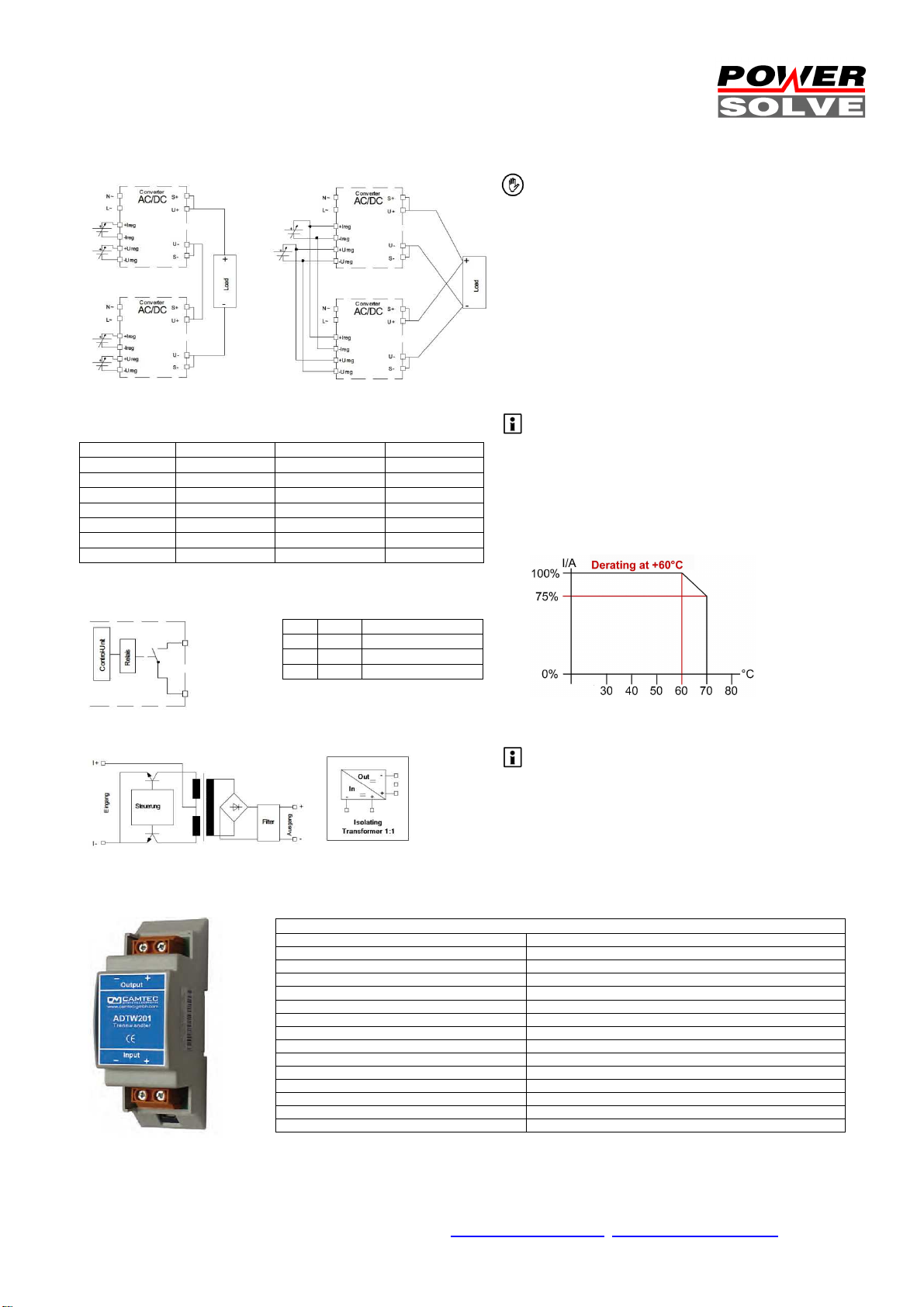
Series Connection (fig.1)
Technical Information ADTW201 external DC
-
Repeater
Series Connection (fig.1) Parallel Connection (fig.2)
Over Voltage Protection (3a) Temperature Derating (fig.3)
Vout OVP Iout
-25°C...+60°C
Iout
+70°C
0...18Vdc 22Vdc 40.0A 30.0A
0...30Vdc 35Vdc 24.0A 18.0A
0...50Vdc 59Vdc 15.0A 11.3A
0...90Vdc 105Vdc 8.0A 6.0A
0...130Vdc 150Vdc 5.5A 4.1A
0...180Vdc 210Vdc 4.0A 3.0A
0...240Vdc 280Vdc 3.0A 2.3A
Power Good (fig.4) Function LED-Bar
30Vac 1000mA
30Vdc 500mA
60Vdc 300mA
CV GRN Constant voltage
CC YEL Constant current
SD YEL shutdown
OT RED Over temperature
ADTW201 Isolating Transformer (fig5)
To increase output voltage equal HSEUIreg can be
connected in series. The control I/O should be galvanic
insulated in the series mode. If not the minus main output
is connected to the control I/O. Use our external option
Isolating Transformer ADTW201 being validated with the
HSEUIreg. Be aware of safety norms if your target output
voltage exceeds safety voltage.
Parallel Connection (fig.2)
To increase the output power up to 5 HSEUIreg can be
parallel connected. Advise using busbars to connect
HSEUIreg in parallel. Always use identical length and
identical cross sections to the busbar.
ADTW201 Isolating Transformer (option) (fig.5)
The isolating transformer is used to galvanic isolate
impressed current. The device is self powered. The input
to output ratio is 1:1. For further information seek advice
from page 10.
Derating & Over Temperature (fig.3)
If the ambient temperature exceeds trigger pint >70°C the
HSEUIreg shuts down (metering point 10mm from
outside device). After being recovered from over
temperature the device restarts automatically to normal
operation.
OVP Over Voltage protection (3a)
The HSEUIreg features over voltage protection.
Exceeding OVP results in a locked shutdown mode.
Resuming the failure causes automatic restart into normal
operation.
Power Good Signal (fig.4)
Galvanic insulated open with failure, closed at normal
operation.
Powersolve Electronics Ltd., Unit 8A Arnhem Road, Newbury RG14 5RU, United Kingdom
Tel 0044 (0)1635 521858 Fax 0044 (0)1635 523771
(Subject to alterations. This product is not designed to be used in applications such as life support systems wherein a failure or malfunction could result in injury or death)
Input (Ie) 0…20mA, 4…20mA (max. 50mA)
Voltage drop (Uw) Uw>1.5V (Ie=20mA)
Max. apparent ohmic resistance (Ra) 500R @ Ie=20mA
Input Impedance (R) R=Ra+Uw/IE
Barrier Frequency (Fa) Fa=5kHz (-3dB) with Ra=500R @ Ie=20mA
Output 1:1
Ripple / Noise >0,5% with 20mA and Ra=500R
Linear Failure >0,03% / 100R
Transient oscillation current 35uA
Latency 150us 0..20mA, Ra=500R, 10…90%
Isolation Voltage Input/output 500V
Operation Temperature 0…50°C
Temperature Drift Approx. 15ppm/K
Weight 21g
Ordering Information Part No: 304.1090.001CA
www.powersolve.co.uk sales@powersolve.co.uk
p.6/9 05.12D

Power Sink (Option)
Dynamic re
sponse
Technical Data
The power sink option features returned power to be terminated very quickly. The power sink records the output power status and guarantees
a constant output voltage. The power sink also provides quicker response time on setting down the output voltage.
Applications sample: DC-drives & ATE test systems
Most of modern dc-drives are controlled by a PWM (pulse wide modulation) controller. Such controllers feature a very flexible speed control
and high efficiency. A disadvantage of PWM controlled drives is the returned power into the system while decelerating the motor. The
dragging of the motor inverts the drive into a generator. The returned power may cause trouble or serious defects to the dc-system, but
definitely slows down the decelerating process of a drive. The returned energy is not terminated quickly enough and results in rising system
voltage. An integrated load, called power sink, terminates the returned power very quickly and enables the drive to small dynamic latency
(see figure).
ATE test-systems require quick down programming of the output voltage. Most ATE applications need to drag down the output voltage to 0V
as a new testee is put into the system. A power supply without a power sink is simply not quick enough to terminate the energy at the output
capacitors. Therefore an electronic power sink manages the output voltage to reset very quickly. Overall test time is being reduced and the
testee is uncontrolled transient voltage protected.
Conventional power supply circuit
simplified, without power sink
Power sink equipped power supply
Latency of conventional power supply Latency of power sink
equipped power supply
Conventional power supply:
breaking power charges output
capacitor Co
Power sink equipped power
supply: absorbs breaking energy
Dynamic reaction of conventional
power supply: uncontrolled voltage
rises with negative reverse current
Dynamic reaction of power sink
equipped power supply:
load current switches between
positive and negative
Powersolve Electronics Ltd., Unit 8A Arnhem Road, Newbury RG14 5RU, United Kingdom
Tel 0044 (0)1635 521858 Fax 0044 (0)1635 523771
(Subject to alterations. This product is not designed to be used in applications such as life support systems wherein a failure or malfunction could result in injury or death)
www.powersolve.co.uk sales@powersolve.co.uk
A common power supply is
usually not designed to absorb
returned power from its
connected load.
The negative load current will
recharge the capacitor Co. The
output voltage starts rising and
get out of control.
This is essential to the
mathematic formula dv/dt=i/C.
As an electronic power sink
module is equipped to the
power supply unit, the output
voltage will constantly being
kept at the desired level. The
power sink provides very quick
dynamic response. The output
voltage only rises to a minimal
notching ratio for a very short
spell.
Using a power supply unit
without equipped power sink in
such application may result into
serious damage or uncontrolled OVP activity to the
power supply unit.
Outline Factory
Continuous
Power
Capability
Peak Power
Capability
built in
5W
10W
(100ms)
p.7/9 05.12D

Coating
Option
We offer the USEUIreg-series with optional coating. It is to be used in e.g. dusty, dirty, high humidity, or in awaiting quick temperature
Test Time A B C
¹) D
Type Test
Factory Test
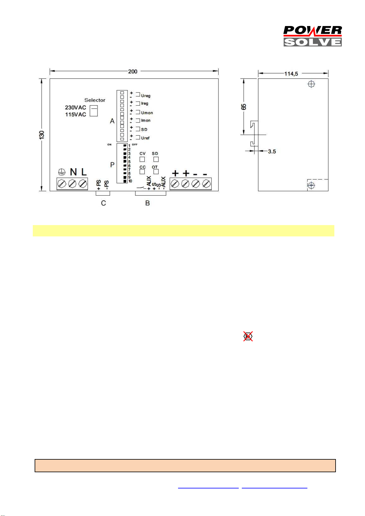
Field Test
Terminal Connec
ts:
Mechanics & Installation of the HSEUIreg
Backplate Option
changes. Short circuit and corrosion at print board lines and at solder points can be prevented. The coat itself is a transparent acrylic
resin. It is procured with a robotics varnishing machine.
Peters SL 1306 N-FLZ (transparent) IEC60216-1 2001, IPC-CC-830B, UL listed as permanent coating FileNo.: E80315 , UL94V-0
Ordering Information: ad extension C to the type number: HSEUIreg04801.180TC
Type test and factory tests are
60s 2500Vac 3000Vac 500Vdc 500Vdc
5s 2000Vac 2000Vac 500Vdc 500Vdc
2s 2000Vac 2000Vac 500Vdc 500Vdc
¹) ≥90Vdc = 1500Vac
a) Use approriate test equipment which apply the voltage with a slow ramp
b) Connect L1 and N together, as well as all output poles
c) Use only AC test-voltages with 50/60Hz. The output voltages is floating and has
no ohmic reference to ground.
d) If testing output voltages are ≥60Vdc remain to security directives.
Use only isolated screw drivers to adjust output voltages.
AC Main Input
GND common
N - wire
L - wire
DC Mains Outputs
DC + voltage
DC + voltage
DC - voltage
DC - voltage
Inputs/Outputs
Ureg = programmable voltage input
Ureg = programmable current input
Umon = voltage monitor output
Imon = current monitor output
SD = shut down input
Uref = reference voltage (poti connection)
conducted by the manufacturer.
Do not repeat the test in field.
Field test rules:
Standard Feature Connects
C= external power sink
B= sense connections (S+/-) &
operation failure relay (output)
Stable metal/aluminium housing IP20. To allow adequate convection, a free air space of 50mm (top/bottom) and 5mm (sidewalls) is
required; for active devices 15mm space from the sidewalls. For free air convection it is necessary to install the HSEUIreg horizontal. You
can use the DIN-Rail installation (equiped standard) with our patented 35mm DIN-Rail bracket according to EN60275. It is easy to
mount/dismount while snaping it onto the 35mm DIN-Rail - any tools necessary. A wallmount backplate (option) is availble, too
Powersolve Electronics Ltd., Unit 8A Arnhem Road, Newbury RG14 5RU, United Kingdom
Tel 0044 (0)1635 521858 Fax 0044 (0)1635 523771
(Subject to alterations. This product is not designed to be used in applications such as life support systems wherein a failure or malfunction could result in injury or death)
www.powersolve.co.uk sales@powersolve.co.uk
p.8/9 05.12D
Safety Instructions:
ready to hand.The HSEUIreg must be installed by specialist staff only.
Installation:
1.) The HSEUIreg is designed for systems fulfilling the safety norms of
dangerous voltages/energy and fire prevention
2.) Installation is restricted to specialists only, make sure that the AC
wire system is free of voltage
3.) Opening the HSEUIreg, making any modifications to it, dismounting
any screws from it, operating the HSEUIreg out of specification
and/or using it in appropriate area will unevitably result in loosing
manufactureres guarantee; we decline taking any responsibility for
risk of demages caused to someones health or to any installed
system.
4.) Attention: The HSEUIreg has an internal input fuse. It is necessary
to wire an automatic circuit braker to the line. We suggest to use a
16A-type with B-characteristic. It is verboten to operate the
HSEUIreg without protective earth wired. It essential to install a line
switch before the HSEUIreg.
Please read all warnings and advices carefully before installing or operating the HSEUIreg. Retain this operation manual always
Warnings
Disregard these warnings can cause fire, electic shock, serious
accident and death.
:
1. Never operate the HSEUIreg without Protective Earth
Conductor
2. Before connecting the HSEUIreg to the AC wire system
make all wires free of voltage and assure accidently
switch on
3. Allow neat and professionel cabeling
4. Never open nor try to repair the HSEUIreg by yourself.
Inside are dangerous voltages that can cause electric
shock hazard.
5. Avoid metal pieces or other conductive material to fall into
the HSEUIreg
6. Do not operate the HSEUIreg under damp or wet
conditions
7.
It is verboten to operate the HSEUIreg under Ex
conditions or in Ex-Area
All parameters base on 15 minutes run-in @ full load / 25°C / 230Vac 50/60Hz, as otherwise stated.
Powersolve Electronics Ltd., Unit 8A Arnhem Road, Newbury RG14 5RU, United Kingdom
Tel 0044 (0)1635 521858 Fax 0044 (0)1635 523771
(Subject to alterations. This product is not designed to be used in applications such as life support systems wherein a failure or malfunction could result in injury or death)
www.powersolve.co.uk sales@powersolve.co.uk
p.9/9 05.12D
 Loading...