

Page 1

powersoft_ottocanali_dsp_uguide_en_v2.5
© 2013 Powersof t
Powersoft • Via Enrico Conti, 5 • 50018 Scandicci (FI) • Italy
+39 055 735 0230 • sales@powersoft.it • www.powersoft-audio.com
DO000128 REV 02
Ottocanali 1204
User Guide v 2.5
Ottocanali
1204
ETH
DSP
June 2013
Ottocanali 1204 DSP+ETH
Page 2

▶
2
This page intentionally left blank
Page 3

powersoft_ottocanali_dsp_uguide_en_v2.5
© 2012 Powersoft
Powersoft S.r.l. • Via Enrico Conti, 5 • 50018 Scandicci (FI) • Italy
+39 055 735 0230 • sales@powersoft.it • www.powersoft-audio.com
Ottocanali 1204
User Guide
1 Warnings. ........................................5
1.1 Impor tant Safety Instructions . ......................5
1.2 Warning Notices . .................................5
1.2 .1 Location. ....................................5
1.2.2 Precautions Regarding Installation. ..............5
1.3 Safety Rules . .....................................6
1.4 Speaker Damage . .................................6
1.5 Speaker Output Shock Hazard . ....................6
2 Front and Rear Panel Reference Figures. ................7
3 Welcome. ............................................9
3.1 Introduction ......................................9
3.2 The Ottocanali Series . ............................9
3.3 More Sound and Less Weight . .....................9
4 Installation........................................9
4.1 Unpacking ........................................9
4.2 Mounting . .......................................9
4.3 Cooling . ........................................10
4.4 Operating Precautions ............................10
4.5 Grounding . .....................................10
4.6 AC Mains Connection . ...........................10
4.7 BatFormer® . ...................................10
5 Connections and Operation. .......................13
5.1 Introduction .....................................13
5.2 Front Panel Controls Access .......................13
5.3 Front Panel Adjustments . .........................13
5.3.1 Output Level Adjustments. ...................13
5.3.2 Energy Save.................................13
5.4 Front Panel Monitoring . ..........................14
5.5 Connecting Audio Inputs . ........................15
5.6 Connecting Audio Outputs . ......................15
5.7 Lo-Z and 70V/100V Operations ....................16
5.8 Bridge Mode Connection . ........................16
5.9 Parallel Mode Connection .........................16
5.10 GPIO Operations . ...............................16
5.10.1 Alarms. ...................................16
5.10.2 Remote ON/OFF. ..........................16
5.10.3 Ethernet Port and Remote ID Selection*. .....16
5.10.4 V ext*. ....................................16
5.11 DSP features and operations* . ....................18
5.11.1 What Are DSP Operations?
What Are They For?*. ........................18
5.11.2 DSP Features*. .............................18
5.11.3 Internal Processing Layout*...................18
5.11.4 Locking*. ..................................19
5 .11. 5 O n /O f f *. ..................................19
5.11.6 Preset Mangement*. ........................19
6 Remote Control*. ................................19
6.1 What is Armonía?* . ..............................19
6.2 Connecting The Device* . .........................19
6. 2.1 Net work*. .................................19
6. 2.1.1 DHCP*. ..................................20
6.2.1.2 AUTOIP*. ................................20
6.2.1.3 STATIC IP*. ...............................20
6.2.1.4 Revert From Static IP*. .....................20
6.2.2 Discovery Device*. ..........................21
6.3 Setup Device* . ..................................21
6.3.1 Virtual Device*. .............................21
6.3.2 Real Device*. ...............................21
6.4 File Operations* . ...............................22
6.4.1 Binary Preset File .preset*. ................... 22
6.4.2 Input/Output Curves .icp, .ocp. .............. 22
6.4.3 Channel Preset .chp*. ....................... 22
6.4.4 Device Preset File .pam*. .................... 22
6.4.5 System File .paw*. .......................... 23
6.5 DSP Remote Operations* . ...................... 23
6.5.1 Routing*................................... 23
6. 5.2 Input Eq.*.................................. 23
6. 5.3 Output Eq.*.................................24
6.5.4 Limiters*. ..................................24
6.5.4.1 RMS Limiter*. .............................24
6.5.4.2 Peak Limiter*. .............................24
6.5.5 Locking*................................... 25
6.5.6 On Board Preset Operations*................ 25
6.5.7 Copy & Paste Operations*................... 25
6.5.7.1 Input/Output Eq Curves*. ..................26
6.5.7.2 Channels*. ................................26
Page 4

▶
4
Ottocanali 1204 User Guide
6.5.7.3 Workspace*...............................26
7 Protection.......................................26
7.1 Turn On/Turn Off Muting . ........................26
7.2 Short Circuit Protection . .........................26
7.3 Thermal Protection . .............................26
7.3.1 Thermal Warning. ...........................26
7.3.2 Thermal Shutdown. .........................26
7.4 DC Fault Protection . .............................26
7.5 Input/Output Protection . .........................27
7.6 Check Line Integrity and Impedence Measurement* . 27
7.6.1 Programing Interface and Alarm Blocks
Over view*. .................................27
7.6.2 Input Pilot Tone Detection*. ..................27
7.6.3 Output Pilot Tone Detection*. ................28
7.6.4 Inner Pilot Tone Generator*...................28
7.6.5 Output Load Monitor*. . . . . . . . . . . . . . . . . . . . . . .28
8 User Maintenance.................................29
8.1 Cleaning . .......................................29
8.2 Service . ........................................29
8.3 Dust Removal . ..................................29
9 Warranty........................................29
10 Assistance. ......................................30
11 Technical Specications. ...........................31
11.1 Ottocanali 1204 DSP+ETH . ......................31
11.2 Ottocanali 1204 . ................................32
12 Appendix. ...........................................33
12.1 Setting An IP Policy On ADAU Based Devices
With An External Lantronix Tool* . ................33
12.1.1 Set IP conguration*.........................33
12.1.2 Static IP*...................................33
12.1.3 Revert From Static IP*...................... 34
12.2 Appendix: Output Congurations ..................36
13 Troubleshooting..................................... 40
Page 5

powersoft_ottocanali_dsp_uguide_en_v2.5
© 2012 Powersoft
Powersoft S.r.l. • Via Enrico Conti, 5 • 50018 Scandicci (FI) • Italy
+39 055 735 0230 • sales@powersoft.it • www.powersoft-audio.com
Ottocanali 1204
User Guide
1 Warnings
1.1 Important Safety Instructions
CAUTION
RISK OF ELECTRIC SHOCK
DO NOT OPEN
!
CAUTION: TO REDUCE THE RISK OF ELECTRIC SHOCK, DO
NOT ATTEMPT TO OPEN ANY PART OF THE UNIT . NO
USER-SERVICEABLE PARTS INSIDE. REFER SERVICING TO
QUALIFIED SERVICE PERSONNEL.
“WARNING: TO REDUCE THE RISK OF FIRE OR ELECTRIC
SHOCK , DO NOT EXPOSE THIS APPARATUS TO RAIN
OR MOISTURE. OBJECTS FILLED WITH LIQUIDS, SUCH AS
VASES, SHOULD NOT BE PLACED ON THIS APPAR ATUS”
“TO COMPLETELY DISCONNECT THIS APPARATUS FROM
THE AC MAINS, DISCONNECT THE POWER SUPPLY CORD
PLUG FROM THE AC RECEPTACLE”
“THE MAINS PLUG OF THE POWER SUPPLY CORD MUST
REMAIN READILY ACCESSIBLE”
SAFEGUARDS: Electrical energy can per form many useful
functions. This unit has been engineered and manufactured to
assure your personal safety. Improper use can result in potential
electrical shock or re hazards. In order not to defeat the
safeguards, observe the following instructions for its installation,
use and servicing.
▶
Read these instructions.
▶
Keep these instructions.
▶
Heed all warnings.
▶
Follow all instructions.
▶
Do not use this amplier near water.
▶
Clean only with a dry cloth.
▶
Do not block any ventilation openings.
▶
Install in accordance with the manufacturer’s instructions.
▶
Do not install near any heat sources such as radiators, heat
registers, stoves, or other apparatus (including ampliers)
that produce heat.
▶
Do not defeat the safety purpose of the polarized or
grounding-type plug. A polarized plug has two blades with
one wider than the other. A grounding type plug has two
blades and a third grounding prong. The wide blade or the
third prong are provided for your safety. If the provided
plug does not t into your outlet, consult an electrician for
replacement of the obsolete outlet.
▶
Protect the power cord from being walked on or pinched
particularly at plugs, convenience receptacles, and the point
where they exit from the apparatus.
▶
Only use attachments/accessories specied by the
manufacturer.
▶
Unplug this amplier during lightning storms or when unused
for long periods of time. Refer all servicing to qualied service
personnel. Servicing is required when the amplier has been
damaged in any way. For example if the power-supply cord
or plug have been damaged, if liquid has been spilled or
objects have fallen into the amplier, if the amplier has been
exposed to rain or moisture, if it has been dropped or if it
does not operate normally.
EXPLANATIONS OF GRAPHICAL SYMBOLS:
“The Lightning Flash with arrowhead symbol within an equilateral
triangle is intended to aler t the user to the presence of uninsulated
“dangerous voltage” within the product enclosure that may be of
sufcient magnitude to constitute a risk of shock to persons”.
!
“The exclamation point within an equilateral triangle is intended
to aler t the user to the presence of important operating and
maintenance (servicing) instructions in the literature accompanying
the product”.
1.2 Warning Notices
!
1.2 .1 Location
Install the amplier in a well-ventilated location where it will not
be exposed to high temperature or humidity.
Do not install the amplier in a location that is exposed to direct
sun rays, or near hot appliances or radiators. Excessive heat can
adversely affect the cabinet and internal components. Installation
of the amplier in a damp or dusty environment may result in
malfunction or accident.
1.2.2 Precautions Regarding Installation
Placing and using the amplier for long periods of time on heat
generating sources will affect its performance. Avoid placing the
amplier on heat generating sources. Install this amplier as far as
possible from tuners and TV sets. An amplier installed in close
proximity of such equipment may experience noise or generic
performance degradation.
WARNING. To prevent re or electric shock:
▶
The ventilation openings must not be impeded by any item
such as newspapers, tablecloths, cur tains etc; keep a distance
of at least 50cm from the front and rear ventilation openings
of the amplier.
▶
Do not expose this amplier to rain or moisture.
▶
This equipment must not be exposed to dripping or splashing
liquids: objects lled with liquids, such as vases, must not be
placed on the amplier.
Page 6

▶
6
Ottocanali 1204 User Guide
1.3 Safety Rules
!
▶
This device must be powered exclusively by earth connected
mains sockets in electrical networks compliant to the IEC 364
or similar rules.
▶
It is absolutely necessary to verify this fundamental
requirement of safety and, in case of doubt, require an
accurate check by qualied personnel.
▶
The manufacturer cannot be held responsible for damages
caused to persons, things or data due to an improper or
missing ground connection.
▶
Before powering this amplier, verify that the correct voltage
rating is being used.
▶
Verify that your mains connection is capable of satisfying the
power ratings of the device.
▶
Do not spill water or other liquids into or on the amplier.
▶
Do not use this ampliler if the electrical power cord is frayed
or broken.
▶
Do not remove the cover. Failing to do so will expose you to
potentially dangerous voltage.
▶
No naked ame sources such as lighted candles should be
placed on the amplier.
▶
Provide a sectioning breaker between the mains connections
and the amplier. The suggested device is a 10A/250V AC
(230V AC mains voltage) or 16A/250V AC (110Vac mains
voltage), C or D curve, 10KA.
▶
Contact the authorized service center for ordinary and
extraordinary maintenance.
1.4 Speaker Damage
!
Powersof t Class D ampliers are among the most powerful
professional ampliers available and are capable of producing
much more power than many loudspeakers can handle. It is the
user’s responsibility to use speakers suitable to the amplier and
to use them in a sensible way that will not cause damage.
Powersof t will not be held responsible for damaged speakers.
Consult the speaker manufacturer for power handling
recommendations.
Even if you reduce the gain using the amplier’s front panel
attenuation controls, it is still possible to reach full output power if
the input signal level is high enough.
A single high-power tone can damage high frequency drivers
almost instantaneously, while low frequency drivers can usually
withstand very high, continuous power levels for a few seconds
before they fail. Reduce power immediately if you hear any
speaker “bottoming out” - harsh pops or cracking distortion that
indicate that the speaker voice coil or diaphragm is striking the
magnet assembly.
Powersof t recommends that you use ampliers of this power
range for more headroom (cleaner sound) rather than for
increased volume.
1.5 Speaker Output Shock Hazard
A Class D amplier is capable of producing hazardous output
voltages. To avoid electrical shock, do not touch any exposed
speaker wiring while the amplier is operating.
This manual contains important information on operating your
Powersoft amplier correctly and safely. Please read it carefully
before operating your amplier. If you have any questions,
contact your Powersoft dealer.
Page 7

▶
7
Ottocanali 1204 User Guide
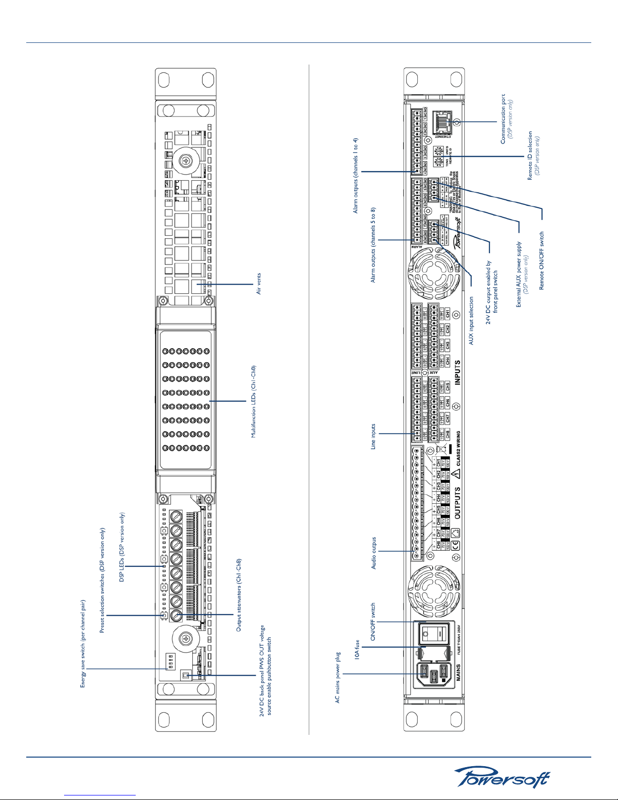
2 Front and Rear Panel Reference Figures
REF. FIGURE 1: Front panel view with closed side panels
Page 8
▶
8
Ottocanali 1204 User Guide
REF. FIGURE 2: Front panel view with opened side panels
REF. FIGURE 3: Back panel view
Page 9
▶
9
Ottocanali 1204 User Guide
3 Welcome
3.1 Introduction
Congratulations on buying a Powersoft Ottocanali amplier!
Powersof t is a leading company in the eld of high efciency
audio power management. The Powersoft Class D technology
has changed the way the world looks at professional audio
amplication: no other amplier’s per formance comes close for
applications demanding high power and long term reliability.
Thanks to amazing reductions in heat output and weight, without
sacricing output powers, Powersoft ampliers can be used in an
unlimited range of PA applications such as opera houses, theaters,
churches, cinema, and theme parks.
3.2 The Ottocanali Series
The Ottocanali series of ampliers are specically designed for
installation applications. The ampliers in this series offer smaller
dimensions, lighter weight and the traditionally amazing sound
quality and reliability of all Powersoft products. The PFC (Power
Factor Correction) feature allows awless worldwide operation
with any AC mains voltage, including110V and 220V.
3.3 More Sound and Less Weight
Class D technology based ampliers are highly efcient, delivering
greater power to speakers with reduced heat dissipation: typical
running efciency of output stages is 95%, with only 5% of input
energy dissipated as heat. This allows for smaller dimensions,
weight and power consumptions.
Contrary to conventional ampliers which achieve highest
efciency only at full rated power output, Class D efciency is
almost independent of output level. Music has an average power
density of 40% of its peak value; this means that other (nonclass D) ampliers can easily generate 10 times more heat than
Powersof t products for the same sound pressure level. This unit
is designed to work with lo-Z (from 4 Ω) and with 70V/100V
distributed lines. It can deliver up to 150 W per channel (at 4 Ω)
or 300 W in bridge mode on 8 Ω. The DSP + ETH version allows
single channel processing and remote control of the amplier.
Powersof t ampliers deliver crystal-clear highs, and a tight, welldened low end: the most accurate reproduction of an audio
signal. Solid time proven design features ensure extremely high
performance in terms of super low total harmonic distor tion,
optimal frequency response, high power bandwidth and damping
factor across a vast number of application scenarios. Powersoft’s
multi patented application of Pulse Width Modulation (PWM)
high frequency sampling techniques is just one of the many factors
contributing to the Ottocanali’s high per formance ratings across
the audio bandwidth.
The Show Always Goes On
The Ottocanali series offers complete protection against any
possible operation error. Every amplier in this series is designed
to work under a large range of possible conditions, delivering
maximum power with maximum safety and an outstanding long
term reliability. Anticipating potential problems at the design stage
means your show always goes on!
4 Installation
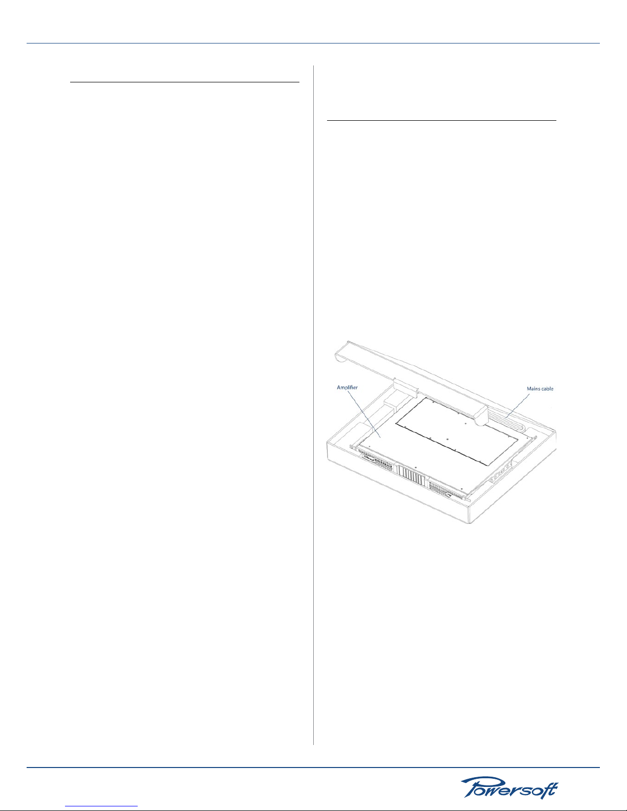
4.1 Unpacking
Carefully open the shipping carton and check for any noticeable
damage; the gure below (FIGURE 1) shows the packing view.
Every Powersof t amplier is completely tested and inspected
before leaving the factory and should arrive in pristine condition.
In the unlikely event that you should encounter any damage,
please notify the shipping company immediately. Be sure to save
all packing materials for the carrier’s inspection.
The Ottocanali box contains the following:
▶
1 Ottocanali amplier
▶
1 x AC Mains cord with 3-pin plug 15A for US, IEC ‘Schuko’
16A for every other nation.
▶
6 x 12 pin Phoenix MC 1.5/12-ST-3.81 1803675 connectors
▶
2 x 4 pin Phoenix MC 1.5/4-ST-3.81 1803594 connectors
▶
1 x 16 pin Phoenix MSTB 2.5/16-ST-5.08 1757158 connectors
FIGURE 1: Ottocanali box
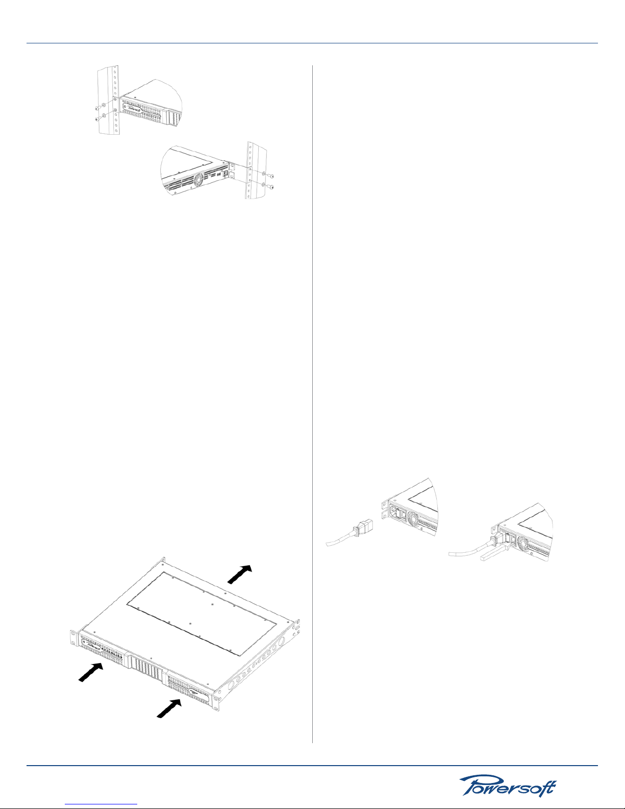
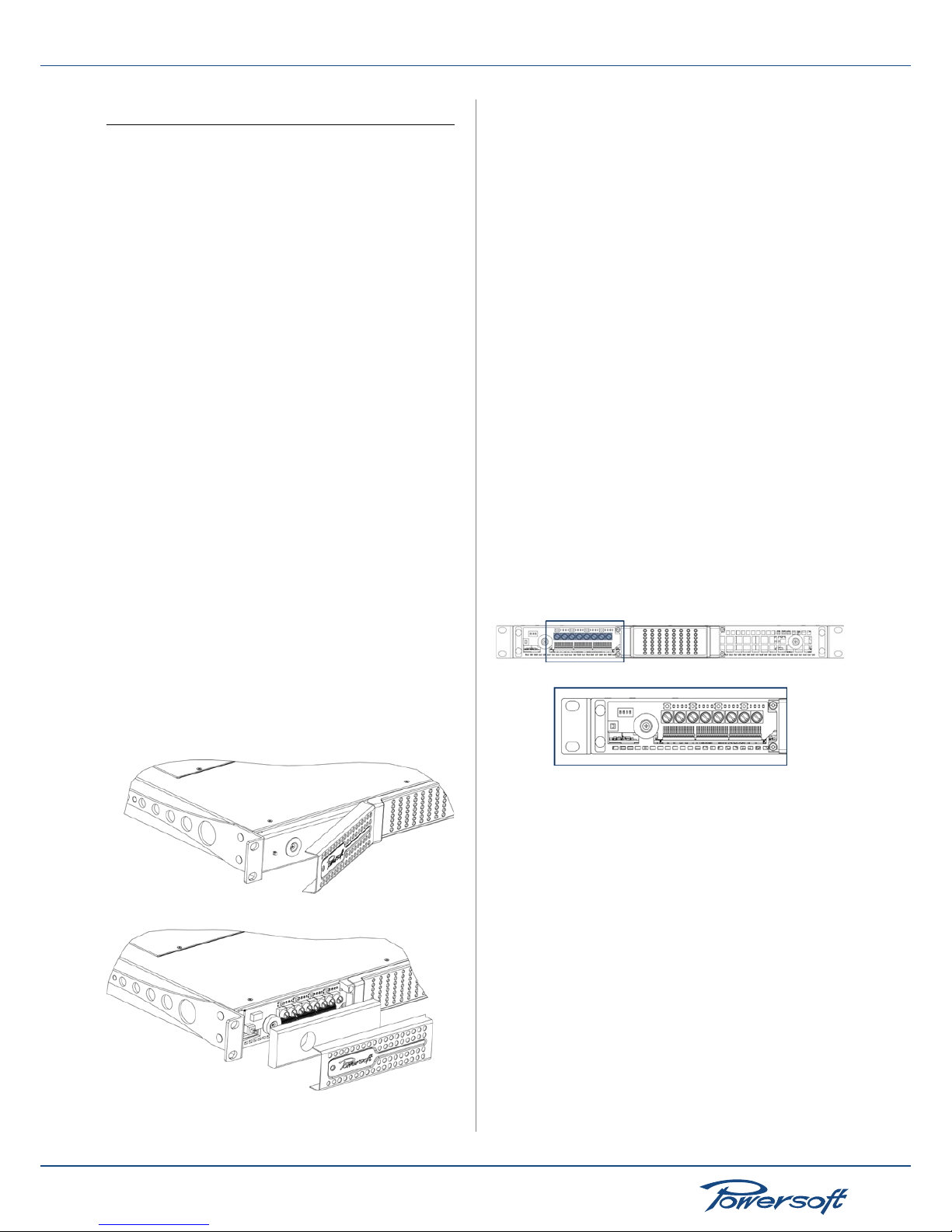
4.2 Mounting
All Powersoft ampliers are designed for standard 19” rack
mounting; there are four front panel holes and two rear-lateral
holes. In order to limit the risk of mechanical damages, ampliers
must be xed to the rack using both frontal as well as rear
mounting holes (FIGURE 2).
Page 10
▶
10
Ottocanali 1204 User Guide
FIGURE 2: Amplier rack mounting holes, front and back
4.3 Cooling
All Powersoft ampliers implement a forced-air cooling system to
maintain low and constant operating temperatures. Drawn by an
internal fan, air enters through the slots in the front panel and is
forced over all components, exiting at the back of the amplier.
The amplier’s cooling system features an “intelligent” variable-
speed DC fan which is controlled by heat sink temperature sensing
circuits: the fan speed will increase only when the temperature
recorded by the sensors rises over carefully predetermined values.
This ensures that fan noise and internal dust accumulation are kept
to a strict minimum. Should however the amplier be subject to
an extreme thermal load, the fan will force a very large volume
of air through the heat sink. In the extremely rare event that the
amplier should dangerously overheat, sensing circuits shut down
all channels until the amplier cools down to a safe operating
temperature. Normal operation is resumed automatically without
the need for user intervention.
When mounting Ottocanali ampliers, the exhaust heat should
be taken into consideration.. Exhaust cooling air is forced out
through the rear of the chassis (FIGURE 3); make sure there
is enough space around the back of the amplier for this air to
escape. Ottocanali ampliers can be stacked one on top of the
other due to the efcient cooling system they are equipped with.
There is however a safety limit to be observed: in case a rack with
closed back panels is used, leave one rack unit empty every four
Ottocanali ampliers installed to guarantee adequate air ow.
FIGURE 3: Forced air cooling: front to back airow
4.4 Operating Precautions
Make sure the power switch is off before attempting to make any
input or output connections.
Make sure the AC mains voltage used is within the acceptable
operating voltage range specied in the Ottocanali documentation
(100V-240V ±10%). Damage caused by connecting the amplier
to an improper AC mains voltage is not covered by the warranty.
By using good quality input and speaker cables, the likelihood of
erratic signal behavior is reduced to a minimum. Whether you
make them or buy them, look for good quality wires, connectors
and soldering techniques.
4.5 Grounding
There is no ground switch or terminal on the Ottocanali Series
ampliers. All shield terminals of input connections are directly
connec ted to the chassis. This means that the unit’s signal grounding
system is automatic. In order to limit hum and/or inter ference
entering the signal path, use balanced input connections.
In the interests of safety, the unit MUST always operate with
electrical safety ear th connected to the chassis via the dedicated
wire in the 3-wire cable. Never disconnect the ground pin on the
AC mains power cord.
4.6 AC Mains Connection
The AC Mains connection is made via the IEC type connector on
the back of the amplier. The PFC feature allows the Ottocanali
to work within a range of different AC mains voltages without the
need to adjust any settings; however, make sure your AC mains
power source operates within the voltage limits indicated on this
manual (100V-240V ±10%). The 10A mains fuse and spare fuse
are located between the on/off switch and the IEC type mains
connector. Please see REF. FIGURE 3.
FIGURE 4: Mains connector and on/off switch
SAFETY WARNING! Ground wires must be connected! Do not
use adapters that disable grounding.
4.7 BatFormer®
It is possible to connect any Ottocanali channel directly to a
70V/100V distributed line using an optional BatFormer. BatFor mers
are specically designed to be easily installed by an authorized
service center.
Page 11
▶
11
Ottocanali 1204 User Guide
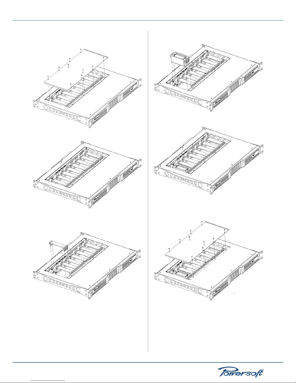
How to install a BatFormer
1. Remove the amplier top panel by removing the (10) screws.
FIGURE 5: Top panel removal
FIGURE 6: Exposed jumper boards
2. Remove the lo-Z connection jumper board by carefully
pulling upward.
FIGURE 7: Jumper board removal
3. Align the BatFormer so that the 6-pin connector faces the
front panel (see gure below).
FIGURE 8: BatFormer insertion
FIGURE 9: BatFormer inserted, top panel removed
4. Carefully insert the BatFormer by gently pressing down on
both sides.
FIGURE 10: Top panel repositioning
5. Reposition amplier top panel and secure with screws.
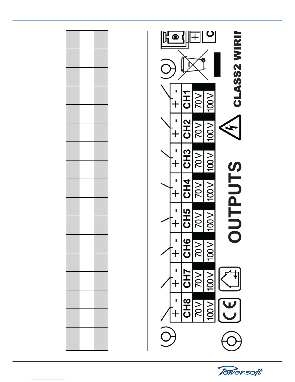
There are silkscreened labels underneath the output connectors
on the back panel that are meant for authorized service centers
to indicate which channels have BatFormers installed and are
therefore capable of driving a 70V or 100V distributed line (see
REF. FIGURE 5).
Page 12
▶
12
Ottocanali 1204 User Guide
Output
CH8-
Spk8_-
Spk4_ -
Output
CH8 +
Spk 8_+
NC
Output
CH7-
Sp k7_-
NC
Output
CH7 +
Sp k7_+
Spk 4_+
Output
CH 6 -
Spk6_-
Spk3_-
Output
CH6 +
Spk 6_+
NC
Output
CH5-
Spk5_-
NC
Output
CH5 +
Spk 5_+
Spk 3_+
Output
CH4 -
Spk4_ -
Spk2_-
Output CH
4 +
Spk 4_+
NC
Output
CH3-
Spk3_-
NC
Output
CH3 +
Spk 3_+
Spk 2_+
Output
CH2-
Spk2_-
Spk1_ -
Output
CH2 +
Spk 2_+
NC
Output
CH1-
Spk1_ -
NC
Output
CH1 +
Spk1 _+
Spk1 _+
Connection type
Singl e end
Lo-Z 70V/100V
Bri dge Lo-Z
REF. FIGURE 4: Output connection mode chart
REF. FIGURE 5: Back panel silkscreened labels
Page 13
▶
13
Ottocanali 1204 User Guide
5 Connections and Operation
5.1 Introduction
This section provides information on amplier connection and
operation. For optimal amplier performance, it is important to
understand the meaning of the information that the Ottocanali
amplier can provide regarding its status and conguration.
This information is available to the user both via front panel
indicators as well as through specic alarm signals broadcasted
from dedicated connectors on the back of the unit. This chapter
will break down all the front panel operations and monitoring
functions the Ottocanali is capable of. The remaining par t of
the chapter will explain how to correctly connect the amplier’s
inputs and outputs.
5.2 Front Panel Controls Access
A number of impor tant controls can be accessed by removing
the front left hand side protective panel bearing the Powersoft
logo. Both silver colored metal panels are attached to the chassis
magnetically and can therefore be removed quickly without the
aid of any specic tool.
The following procedure can be used to remove both the left as
well as the right hand front panels. Removing the right hand panel,
however, does not grant access to any controls and is useful only
for air lter access (see Section 8.3).
To remove the left hand side front panel bearing the Powersoft
logo:
1. Firmly grip the outermost left hand side of the silver colored
panel and pull outwards at an angle, as if opening a door
hinged on the right hand side
2. Carefully slide the metal panel away from the chassis. When
the front panel is removed, the air lter (looking like a shiny
black plastic sponge) will be exposed.
FIGURE 11: Magnetic side panel removal
To reposition the left hand side silver panel:
1. Secure the air lter to the amplier chassis by placing it in its
designated area and press lightly, so that the lter’s central cut
hole can brace the magnetic snap mechanism
2. Align the silver panel’s right hand side to the chassis at the
same angle used to remove it
3. When correctly positioned, the magnetic snap mechanism
will automatically secure the metal panel in place.
The controls positioned behind the lef t hand side silver colored
Powersof t logo panel allow access to a series of important features:
▶
Output channel attenuation adjustment (see Section 5.3.1)
▶
Preset selection, one per channel pair (DSP version only)
▶
AUX Input/Line Input toggle (see Section 5.5)
▶
GPIO operations (see Section 5.10)
▶
Channel pair energy save mode selection (see Section 5.3.2)
5.3 Front Panel Adjustments
There are two types of adjustments that are possible from the
Ottocanali front panel: output level attenuation and energy save
mode.
5.3.1 Output Level Adjustments
Removing the left hand side metallic panel exposes one attenuator
knob for each channel, numbered one through eight starting from
the left hand side. Each channel’s output attenuation level can
be set to any value from 0 to ∞. Attenuation level decreases by
rotating the blue knob clockwise.
FIGURE 12: Front panel left hand side output attenuator s
5.3.2 Energy Save
Energy save capabilities can be activated for each channel pair.
When the energy save mode is activated on a channel pair, the
Ottocanali enters a low power consumption idle state when
no signal activity is detected for more than 4 seconds. Normal
operation is resumed in a matter of milliseconds when an incoming
signal is detected on the channel pair.
Page 14

▶
14
Ottocanali 1204 User Guide
Idle Power Consumption Energy Save Mode OFF
AC Mains
Voltage ( V)
Current (A) Real Power
(W)
Apparent
Power (VA)
Power
Factor
115 0.27 14. 7 31.05 0.47
230 0.33 15.6 75.9 0.21
Idle Power Consumption Energy Save Mode ON
AC Mains
Voltage ( V)
Current (A) Real Power
(W)
Apparent
Power (VA)
Power
Factor
115 0.21 8.7 23.5 0.37
230 0.3 9.3 6 7.2 0 .14
FIGURE 13: Energy save mode on/off: idle power consumption chart
for the Ottocanali without optional DSP
Idle Power Consumption Energy Save Mode OFF
AC Mains
Voltage ( V)
Current (A) Real Power
(W)
Apparent
Power (VA)
Power
Factor
115 0.33 20 38 0.52
230 0.36 21. 2 84.2 0.25
Idle Power Consumption Energy Save Mode ON
AC Mains
Voltage ( V)
Current (A) Real Power
(W)
Apparent
Power (VA)
Power
Factor
115 0.26 13.9 30.6 0.45
230 0.34 14. 6 79 0.18
FIGURE 14: Energy save mode on/off: idle power consumption chart
for the Ottocanali with optional DSP
In order to enable energy saving mode for a channel pair, the DIP
switch on the left hand side of the front panel must be set to OFF
(down).
FIGURE 15: DIP switch for energy save mode
5.4 Front Panel Monitoring
The Ottocanali front panel provides important information on the
state of the amplier. It is important to know and understand the
meaning of every front panel indicator in order to have crucial
information on the operational state of the amplier.
There are two sets of LEDs on the Ottocanali front panel. On the
upper portion of the left hand side of the front panel are 16 LEDs,
4 for each channel pair, available for DSP functions.
FIGURE 16: Front panel left hand side DSP LEDs
For models including a DSP: the lighted LED indicates which preset
is active for that specic channel pair. The rst lef tmost set of 4
LEDs refers to channels 1 and 2, the second set of 4 LEDs refers to
channels 3 and 4 and so on. Preset parameters are dened, set and
modied by connecting the Ottocanali amplier to a computer
using the Armonía Pro Audio Suite software. The pushbutton
on the lef t of each set of 4 LEDs allows to manually select the
preset for that particular channel pair. Pushing the button will cycle
between all 4 available presets.
On the central portion of the front panel of the Ottocanali are 8
columns of 7 LEDs, one column for each channel.
FIGURE 17: Front panel LEDs
Some of these LEDs have multiple signaling modes, e.g. metering
or alarm modes. Their function is summarized in the following
chart:
LED Color Solid ON Blinking
Red Channel output level has
reached clipping limits
OR
Channel has been muted
due to heat sink temperature
rising above 80°C
1)
Yell o w Channel output level is
above -6dB of max output
level
OR
Thermal warning: heat sink
temperature is above 70°C
2)
Green Channel output level is
above -12dB of max output
level
Green Channel output level is
above -24dB of max output
level
Green Input signal is above -60dBV
Green Channel is ready
Green -- AUX inputs
are selected
FIGURE 18: Front panel LEDs chart
1)
Even if only one channel causes thermal overload, all channels
are muted and all red LEDs are on.
Page 15

▶
15
Ottocanali 1204 User Guide
2)
Even if only one channel causes thermal warning, all yellow LEDs
are on.
5.5 Connecting Audio Inputs
Audio input connections are made via two 12-pin Phoenix MC
1.5/12-ST-3.81 terminal block connectors:
FIGURE 19: Audio input terminal block connector
Input connectors are placed on the back of the Ottocanali and
grouped in two rows:
FIGURE 20: Rows of input connectors
▶
The topmost line of connectors is for line input
▶
The second row of connectors is for auxiliar y input
Line Input/Aux Input toggle:
The amplier switches from line inputs to auxiliary inputs when a
constant voltage in the 12V to 30V range is applied to the “AUX
SEL” connector. When this voltage is removed from the “AUX
SEL” connector, the unit switches back from auxiliary inputs to
line inputs.
FIGURE 21: AUX SEL connector
The Ottocanali amplier provides an additional procedure to
switch from line inputs to auxiliar y inputs. The “PWS OUT”
connector can provide a 24V DC (0.2 A max, symmetrical with
respect to ground) when enabled by the left hand front panel
toggle switch.
FIGURE 22: AUX SEL and PWS OUT connection
FIGURE 23: PWS OUT por t on the back of the Ottocanali amp
By connecting the “PWS OUT” connector to the “AUX SEL”
(see FIGURE 22) the front panel switch will toggle between line
inputs and auxiliar y inputs. The following diagram explains the
relationship between the front panel toggle switch and the PWS
OUT port.
FIGURE 24: PWS OUT port vs front panel switch diagram
5.6 Connecting Audio Outputs
Warning! Lethal voltage levels may be present at the loudspeaker
connectors when the amp is turned on!
A 16-pin Phoenix MSTB 2. 5/16-ST-5.08 terminal block connector
is provided for the amplier’s output connections. The + pin of
the connector corresponds to the positive output of the channel.
Ensure that the speakers are connected to the Ottocanali output
with the correct polarity.
FIGURE 25: Audio output terminal block connector
Both bridge as well as single end output connection modes are
possible and can be mixed: for example, channels 1 and 2 can
Page 16

▶
16
Ottocanali 1204 User Guide
be connected in bridge mode, while channels 3 and 4 can be
connected single end.
REF. FIGURE 4 summarizes common connection modes with
corresponding connection polarities. Speaker cables are labeled
as spk X_+ and spk X_-, where X represents the speaker number.
5.7 Lo-Z and 70V/100V Operations
Any channel of the Ottocanali amplier can drive either a lo-Z or
a 70V/100V (hi-Z) line. In order to connect any channel’s output
to a 70V/100V line, the factory supplied connection jumper must
be replaced with a BatFormer (optional). Please refer to 4.7 for
instructions on how to correctly install a BatFormer. BatFormer
installation must be carried out by authorized ser vice centers.
5.8 Bridge Mode Connection
Bridge mode connection of outputs is possible only in lo-Z
operational mode. Bridging of adjacent channels is allowed for the
following pairs: channels 1 with 2, 3 with 4, 5 with 6, 7 with 8.
Bridiging is NOT possible for other pairs, for example channels
4 and 5. In order to obtain a bridge connection of the outputs,
inputs must be connected in parallel and outputs in series on
a minimum load of 8 Ω . Please refer to REF. FIGURE 6 for a
connection diagram example.
5.9 Parallel Mode Connection
Parallel connection of output channels is allowed only for hi-Z
operational modes; this means that in order to connect output
channels in parallel, these MUST be equipped with optional
BatFormers. Only the following channel pairs can be connected in
parallel: 1 with 2, 3 with 4, 5 with 6, 7 with 8. Parallel connection of
channels 4 with 5, for example, is not allowed. In order to obtain
this kind of connection, both the input channel pair as well as the
output channel pair must be connected in parallel. Please refer to
REF. FIGURE 7 for a connection diagram example.
5.10 GPIO Operations
General Purpose Input/Output Operation (GPIO) refers to a
generic two pin contact (balanced or unbalanced) that can control
or can be controlled by another system. The Ottocanali’s GPIO
system implements digital trigger signals to broadcast alarms or
allow remote unit on/off switching.
5.10.1 Alarms
To ensure problem-free and efcient interaction with external
devices, the Ottocanali provides two 12-pin Phoenix MC 1.5/12ST-3.81 connectors on the back panel.
FIGURE 26: Back panel alarm output connectors
These contacts are used to report potentially dangerous faults or
generally unsafe operation conditions by toggling alarm switches
relative to events such as:
▶
DC presence at the outpu t: when a dange rous DC component
is present in the output power signal
▶
Thermal stress: when heat dissipation is not sufcient and
heat sink temperature rises.
For a detailed account of protective measures relative to these
alarms, please see Chapter 7.
5.10.2 Remote ON/OFF
By applying 24V DC (range from 15V to 30V DC) to the “REM
OFF” connector located at the back of the Ottocanali, the
amplier can be remotely switched on and off. When a 24V DC
voltage is applied to the REM OFF 2-pin Phoenix MC 1.5/4-ST-
3.81 connector, the amplier switches off immediately. When the
24V DC voltage is removed, the amplier switches back on as per
normal boot up operation.
FIGURE 27: REM OFF connector
5.10.3 Ethernet Port and Remote ID Selection*
The rear panel of the Ottocanali has one RJ45 port, 100Mbit
autosense Ethernet port for networking purposes. Below these
ports are two numeric encoders that enable remote ID selection,
needed to identify the amp when it is connected remotely. The
left hand side dial sets the tens while the right hand side sets the
units. Valid ID numbers go from 01 to 99.
FIGURE 28: REM OFF connector
5.10.4 V ext*
The “V ext” terminal, located on the rear panel of the Ot tocanali, is
used to supply the amplier’s internal Ethernet controller with the
minimum required power for remote on/off switching operations.
When the V ext port is powered by and external 9 V- 12 V DC
(1 A) power supply, the Ethernet controller is enabled to listen for
incoming connections such as device power-on commands.
Page 17

▶
17
Ottocanali 1204 User Guide
REF. FIGURE 6: Bridge mode output connection of channel 1 and channel 2, lo-Z only
REF. FIGURE 7: Parallel output connection of channels 1 and 2, Hi-Z only (both channels must be equipped with optional BatFormers)
Page 18

▶
18
Ottocanali 1204 User Guide
5.11 DSP features and operations*
5.11.1 What Are DSP Operations? What Are They For?*
The main purpose of Digital Signal Processing (DSP) operations is
to allow the end user to program signal handling and processing
in order to:
1. Select and handle the source signal
2. Process the signal for system operation
3. Process the signal to improve multi way speaker sound quality
and protect speaker drivers
Furthermore, the DSP allows access to real-time information
on the internal device operation, which allows better and faster
amplier response in terms of control as well as providing the
end user with reliable information on what’s happening inside the
device.
5.11.2 DSP Features*
The Ottocanali amplier DSP is based on the DSP-C, a
multiplatform board used in many Powersoft products. Based on
Analog Devices’ ADAU 1701, the DSP-C board’s exible design
caters a wide range of users: from the speaker manufacturer
to the end user of rack ampliers. The DSP-C provides both a
completely programmable DSP to the experienced user as well as
a complete tool with remote control for the end user. The ADAU
1701 device is a xed point DSP with 26-bit resolution for the
internal path and 56-bit for internal processing. The board also
provides full remote control through Armonía Pro Audio Suite.
The Ottocanali DSP is modular for any channel pair, meaning, for
example, one module is available for channels 1 and 2 and another
for channels 3 and 4 and so on. Keep in mind that the modules
are physically separated, therefore input or output from different
modules can’t be mixed together.
Input routing selection and internal signal route. Keep in mind
that due to the internal structure it is impossible to mix signals
between non adjacent channels, for example channels 1 and 4
cannot be mixed together but only channels 1-2, channels 3-4,
channels 5-6 and channels 7-8 can. The following congurations
are possible for any channel pair.
▶
Mono input from IN1
▶
Mono input from IN2
▶
2 inputs – 2 outputs
▶
Mono mix IN1&IN2
Input section, allows system operation to improve sound for a
specic zone, group of speakers, room, etc. The input section
provides an input eq for any input channel with the following
features.
▶
5 biquad lters, any lter can become PEQ, shelving hi-lo
pass, all pass
▶
Delay of 16 ms
▶
Gain between -40 dB and 6 dB
▶
Mute
▶
Reverse polarity
Output section, allows multiway cabinet equalization and
protection. The output section comprises an output eq and a
limiter (peak and RMS) for each channel.
EQ feature:
▶
8 biquad lters, any lter can become PEQ, shelving hi-lo
pass, all pass. The crossover functions are obtained using one
to four biquad lters for each crossover.
▶
Gain between -40 dB and 6 dB
▶
Mute
▶
Reverse polarity
Peak limiter feature:
▶
Threshold, 10 – 45 V. With 0.5 V steps
▶
Hold time, 0 – 2 sec. With 1 ms steps
▶
Release time, 0 – 2 sec. With 1 ms steps
Rms limiter feature:
▶
Threshold, 13 – 312 W @ 8 Ω. With step of 1 W
▶
Attack time, 2 – 4500 ms. With step of 1 ms
▶
Hold time, 0 – 1 sec. With step of 1 ms
▶
Release time, 4 – 4500 ms. With step of 1 ms
5.11.3 Internal Processing Layout*
The following gure summarizes the internal DSP processing signal
path.
FIGURE 29: DSP processing blocks
NOTE: The following information is valid for any single DSP
module (2 channels). The Ottocanali is formed by 4 completely
independent modules.
Input routing, the following congurations are available:
▶
1 input-2 ouputs, the input is routed from channel 1 to both
channels
▶
1 input-2 ouputs, the input is routed from channel 2 to both
channels
▶
2 inputs-2 outputs, the inputs are routed on the respective
output channels
▶
2 inputs-2 outputs, the input is routed from channel 1 and
channel 2 and mix togther; the mono mix function sums the
two sources and halves their summed level
Page 19

▶
19
Ottocanali 1204 User Guide
Output section. Ever y module provides each channel a set of
8 biqudratic lters and a complete set of limiters for protection
purposes.
▶
Output eq: 8 biquad lters can be chosed for shaping (PEQ,
shelving, etc) but these are shared between the crossovers.
Each crossover can consume 1 to 4 biquad lters, depending
on the crossover slope. The char t below illustrates a number
of crossover congurations. Mixed crossover congurations
are possibile (e.g. HP 12 dB/oct, LP 24 dB/oct)
1 xover
Slope 6/12
(db/oc t)
Slope 18/24
(db/oc t)
Slope 30/36
(db/oc t)
Slope 40/48
(db/oc t)
Free biquad
lters
remaining
7 6 5 4
2 xover
Slope 6/12
(db/oc t)
Slope 18/24
(db/oc t)
Slope 30/36
(db/oc t)
Slope 40/48
(db/oc t)
Free biquad
lters
remaining
6 4 2 0
▶
Peak limiter for every output
▶
RMS limiter for every output
5.11.4 Locking*
The locking mechanism allows to lock macro proper ty values
based on the functional sub section and on the channel base of
the device; the lockable sub sections are:
▶
Input routing:
▶
Routing selection
▶
Input Section
▶
Equalizer
▶
Output Section
▶
Equalizer
▶
RMS limiter
▶
Peak Limiter
Every channel subsection is independently lockable.
5.11.5 On/Off *
The on/off function is available when an external voltge is supplied.
Please refer to Section 5.10.4 for further information.
5.11.6 Preset Mangement*
The DSP allows to manage up to 4 presets per module and its
associated channel pair. Each preset contains information on the
following:
▶
Input routing
▶
Input Section
▶
Output Section
▶
Properties locking
The preset is handled by the client as a le with the .preset
extention, see Section 6.4.1 for fur ther information.
These presets can be selected via a preset selection button on the
front panel of the amp. There is one button for each DSP module
(see Section 5.4). The manual preset selection function is disabled
if the amplier is remotely controlled by any client.
WARNING: selecting a preset with a rear button or via remote
control will interrupt the audio stream for some seconds.
WARNING: store the modied preset before turning the unit off
or all changes will be lost. (Please refer to Section 6. 5.6 on how to
access this feature).
NOTE: selecting presets with the rear button is enabled only if
remote control is NOT active.
6 Remote Control*
The Ottocanali DSP allows full amplier remote control with
Powersof t’s sof tware client Armonía. Other third par ty clients are
also available.
6.1 What is Armonía?*
Armonía is a software environment entirely developed in-house by
Powersof t. Its two main features are full end user remote control
of the amp and its signal processing capabilities. The intuitive
inter face provides reliable information and real time control of all
DSP functions. Refer to the Armonía manual for installation and
conguration of the client software.
6.2 Connecting The Device*
This chapter illustrates how to setup the remote control of one
or more ampliers.
6.2.1 Network*
Ottocanali ampliers come with one rear RJ45 port for remote
device communication, using the IP layer and the UDP protocol.
Factory default settings are DHCP/AutoIP, but a xed IP policy can
also be adopted.
FIGURE 30: Rear Ethernet port and ID selection
Page 20

▶
20
Ottocanali 1204 User Guide
6.2.1.1 DHCP*
When the data cable is connected the amplier begins DHCP
handshaking. If a DHCP server is present on the network , the unit
is ready to be remotely controlled.
6.2.1.2 AUTOIP*
Every device tries to set up network communication when the
data cable is plugged in and connected to another device (PC,
switch, etc.). If a DHCP server is not active in the device network
the units initiates a stateless address auto-conguration. It self
assigns a link-local address of the type 169.254.x.y with a subnet
mask 255.255.0.0. Please make sure that your PC is in the same
subnet of the unit. Modern operating systems provide Zeroconf
features for network auto-conguration.
6.2.1.3 STATIC IP*
Ottocanali Series devices can be set up with a static IP (or any
other IP policy) with the Armonia control software. In order to set
up the IP address please follow the following steps:
▶
Connect the device in a network with or without DHCP (see
the the previous paragraph).
▶
Discover the device and import it in the workspace (refer to
the Armonía user guide).
▶
Go to the device scheme tab and select the Network Settings
button.
FIGURE 31: Enter the network settings
▶
Select the Static addressing mode from the combo box
FIGURE 32: Select the static IP policy
▶
Inser t the desired IP Address and network mask, specifying
the gateway necessary only in complex LANs.
FIGURE 33: Insert IP, subnet and net mask in the form
▶
Click apply settings button.
WARNING: the device is reachable only from PCs in the same
subnet mask, if this information is lost, you need to re-init the
network device with a third-par ty software. Refer to Section 12.1.
▶
When done, the device network will restart automatically.
About 15 seconds are necessar y for the device to reconnect.
6.2.1.4 Revert From Static IP*
If for any reason re-programming the IP address or the IP policy
of your unit should be necessary, follow the instructions in the
previous chapter and make a different selection when assigning
the IP. For example, should you need to revert the device to the
automatic (DHCP, Zerocon) IP settings, please follow these steps:
▶
Connect the device in a network with or without DHCP (see
the the previous paragraph).
▶
Discover the device and import in the worksapace (refer to
the Armonía user guide). Device and PC must use the same
subnet. If you are not able to reconnect the device please
follow the guide on Section 12.1.
▶
Go to the device scheme tab and select the Network settings
button.
FIGURE 34: Enter the network settings
▶
Select the Static addressing mode from the combo box
▶
Click apply settings button.
Page 21

▶
21
Ottocanali 1204 User Guide
▶
When done, the device network will restart automatically.
About 15 seconds are necessar y for the device to reconnect.
6.2.2 Discovery Device*
In order to start remote operation on the device connected
to your network, it must be discovered and imported into the
Armonía workspace.
FIGURE 35: A real device controlled by Armonía
To setup the device follow the instructions in the next chapter,
referring to the Armonía user manual for basic operations.
6.3 Setup Device*
There are two ways to congure the device, based on your needs
and on the availability of the real device. The main difference is
that you can either work with virtual devices before going online
and send the setup to the units remotely or you can operate on
the physical unit directly.
6.3.1 Virtual Device*
If for some reason the devices are not available, conguration must
be carried out via virtual devices or a system of virtual devices.
▶
Select the device from the models window
FIGURE 36: Select with left click the virtual unit
▶
Drag and drop in the Workspace
FIGURE 37: Drag&Drop the selected unit in the workspace
▶
If you already have a device preset (.pam) you can import it
by right clicking
FIGURE 38: Left click to select (the blue rectangle appears) and right
click for import
▶
You can modify any DSP value following the instructions in
Section 6.5
At this point you can save and load the system le (.paw) at a later
time. Please refer to the Armonía documentation. If the devices
are ready for remote control you can associate the virtual device
to the real device. To do so, please follow the instructions in the
next section 6.3.2.
6.3.2 Real Device*
Working on the real device remotely is also possible. In this case all
changes made to a device are immediately audible.
In order to work on a real device:
▶
Connect the device and discover the connected units. (see
Section 6.2.2)
▶
Drag the remote device into the workspace onto the vir tual
device
FIGURE 39: Drop the discovered device on the virtual device; when
the arrow appears, release the left mouse button.
Page 22

▶
22
Ottocanali 1204 User Guide
▶
If the internal device setup is different you’ll be prompted to
select the realignment direction
FIGURE 40: Realign window, asking for synchronization
By selecting YES the device setup is transmitted from the vir tual
device to the real device. By selecting NO the device setup is
transmitted from the real device to the virtual one.
WARNING: by answering “yes” to the realignment question, the
Ottocanali device loses data on the selected preset slot.
▶
It is now possible to operate on the device. Refer to Section
6.5) for all possible operations.
WARNING: remember that turning off or disconnecting the
power plug without saving changes on any internal memory slot
leads to data loss. Before turning off, save the data on any internal
slot or export to a .pam le.
6.4 File Operations*
There are several impor t/export possibilities from/to les on an
Ottocanali unit. This section contains an explanation of all possible
cases.
WARNING: due to the internal structure of the device, some of
these le operations can cause a temporar y interruption of audio.
6.4 .1 Binary Preset File .preset*
Handling of the internal binar y preset of an Ottocanali DSP
module is possible in the preset tab of the device.
FIGURE 41: Ottocanali, has four DSP modules, recognizable by the left
number 1/2/3/4 that represnts the slot of every modules.
▶
EXPORT, export the actual preset slot to a .preset le.
WARNING: if the actual playing preset wasn’t saved before
expor t, the exported binary will be the last stored binar y and not
the current playing preset.
▶
IMPORT, save a .preset le on the selected slot and recall
that slot.
WARNING: this leads to a couple of seconds interruption of the
audio stream.
WARNING: the data contained in a .preset le irreversibly
modies a preset slot and its internal layout.
6.4.2 Input/Output Curves .icp, .ocp
From the input or output tab of an Ottocanali device, impor t/
expor t of the current equalization cur ve is a straightforward
procedure.
FIGURE 42: The output eq: there are 4 possibile choices to handle
the cur ve.
WARNING: all changes will be lost if the preset is NOT stored on
board before unplugging the unit from the mains.
6.4.3 Channel Preset .chp*
Impor t/expor t of the current playing processing from/to a le is
possible by starting from the device’s layout.
FIGURE 43: All possibile channel operations are avabile by right
clicking on the respective channel.
Imported and/or exported data is:
▶
Input eq
▶
Output eq
▶
Limiters
WARNING: all changes will be lost if the preset is NOT stored on
board before unplugging the unit from the mains.
NOTE: importing channel preset les doesn’t modify the internal
structure of a device and therefore doesn’t lead to an audio
interruption
6.4.4 Device Preset File .pam*
The preset le allows to import /expor t entire dumps of the
device. An expor ted .pam le allows to completely replicate the
DSP process on another device. In order to impor t/expor t a .pam
le:
Page 23

▶
23
Ottocanali 1204 User Guide
▶
Select the device (a blue rectangle will appear)
▶
Right click on the selected device
▶
Click on import/export
FIGURE 44: The .pam import/export operation from the workspace.
Note the blue rectangle on the selected device.
When impor ting a .pam le you’ll be prompted for a decision on
the realignment policy to adopt.
By selecting yes, the device setup is transmitted from the virtual
device to the real device. By selecting no, the device setup is
transmitted from the real device to the virtual device.
WARNING: importing a .pam le leads to a shor t interruption of
the audio stream.
WARNING: importing a .pam le overwrites the current preset
slot on the device. Any previous data on the slot will be erased.
6.4.5 System File .paw*
Saving or opening a systems le permits the storage of the entire
processing of the current device impor ted in the workspace. For
more information on system conguration, please refer to the
Armonía manual.
The save operation may be seen as a large .pam export of the
entire device; on the other hand, opening a .paw le is equivalent
to performing a large .pam impor t on multiple devices. The user
will be prompted for multiple realignment decision on any desynchronized devices.
If the question is answered with:
▶
YES, the device specied in the window will be aligned to the
data in the .paw le.
▶
YES TO ALL, all the devices will be aligned to the data in the
.paw le.
▶
NO, the device specied in the window will NOT be aligned
to the data in the .paw le but the data will be reloaded from
the device.
▶
NO TO ALL, all the devices will NOT be aligned to the data
in the .paw le bu t the data will be reloaded from the devices.
WARNING: during import or preset manager operations the
save .paw function is disabled.
6.5 DSP Remote Operations*
WARNING: due to the internal structure of the system some of
the following le operations can lead to a short audio interruption.
WARNING: all changes will be lost if the preset is NOT stored on
board before unplugging the unit from the mains.
6. 5.1 Routing*
It’s possible to select an independent routing for any channel pair.
In order to change the routing it is necessary to follow the steps
below:
▶
Enter the device UI and select the scheme tab.
▶
Click on one of the 4 input routing button. (One for any
modules).
FIGURE 45: The routing section.
▶
Select the routing between the 4 possible choices.
FIGURE 46: Four possible selections.
6.5.2 Input Eq.*
The Input Eq. is intended for system operations. The input eq
provides a range of biquad lters that can act as any generic IIR
lter. Refer to Section 5.11.3 for more information. From the input
eq page, the frequency response of each channel can be adjusted
Page 24

▶
24
Ottocanali 1204 User Guide
in several ways. Discrete time delays can also be inserted. The
presence of every input eq used in the device layout is repor ted
on the tabbed channel on the bottom left hand side of the screen.
The frequency response cur ves, together with other View items,
are color coded: light blue for channel 1, red for channel 2, light
green for channel 3, yellow for channel 4, dark blue for channel
5, purple for channel 6, dark green for channel 7 and orange
for channel 8. Every channel allows regulation of lters, mute,
gain, delay and polarity. The frequency response (and/or phase
response) curve displayed is always obtained as the combined
response of all currently active lters.
FIGURE 47: The input eq layer.
6.5.3 Output Eq.*
This page’s general appearance is similar to that of the Input
Equalizer page, but presents several impor tant differences. The
Output Eq. curve the amplier employs is meant to be created from
the speaker manufacturer’s data for the par ticular loudspeaker
cabinets or arrays the amplier will be driving. It provides a range
biquad lter that can act as crossover or generic IIR lter. Refer to
Section 5.11.3 for more information. From this page, the frequency
response of each channel can be adjusted in several ways. Discrete
time delays can also be inserted. The presence of every output eq.
present in the device layout is reported on the tabbed channel on
the bottom lef t hand side of the screen. The frequency response
curves, together with other View items, are color coded: light blue
for channel 1, red for channel 2, light green for channel 3, yellow
for channel 4, dark blue for channel 5, purple for channel 6, dark
green for channel 7 and orange for channel 8. Ever y channel allows
regulation of lters, mute, gain, delay and polarity. The displayed
frequency response (and/or phase response) cur ve is always
obtained as the combined response of all currently active lters.
FIGURE 48: The output eq layer.
6.5.4 Limiters*
The function of the limiters is to protect voice coils from burning
out due to excess power being delivered over an extended period
of time or from excessively large signal peaks by limiting the
maximum output voltage of the amplier. The limiter window is
accessible by clicking on the limiter block in the device layout view.
Every channel limiter is color coded:light blue for channel 1, red
for channel 2, light green for channel 3, yellow for channel 4, dark
blue for channel 5, purple for channel 6, dark green for channel 7
and orange for channel 8.
FIGURE 49: The limiters window.
6. 5.4.1 RMS Limiter*
Electromechanical transducers are highly inefcient; as such
they transform a signicant amount of input power into heat.
The function of the RMS limiter is to protect the voice coils of
speaker drivers from burning out due to excess power being
delivered over an extended period of time. The RMS limiter is set
by selecting a desired maximum power value but acts by limiting
output voltage; by applying Ohm’s law with a xed reference 8
Ohm load, the output voltage level corresponding to the desired
maximim output power value is calculated as the square root of
power times the load resistance (8 Ohm). It is possible to set the
values of:
▶
Threshold in Watts, with respect to an 8 Ohm load.
▶
Attack time is the time between the moment the output
voltage exceeds the threshold and the moment of the onset
of the limiting action.
▶
Hold time is the length of time during which the limiting
action is maintained before the gain returns to normal levels
because the output voltage drops below the threshold level.
▶
Release time is the leng th of time over which the limiting
action is reduced and the gain is returned to normal follwing
the drop of the output voltage below the threshold level.
6.5.4.2 Peak Limiter*
The function of the peak limiter is to protect voice coils from
excessively large signal peaks by limiting the maximum output
Page 25

▶
25
Ottocanali 1204 User Guide
voltage of the amplier. It’s possible set the values of:
▶
Threshold in Volts: the amplier max output voltage level
corresponding to the maximum displacement of the speaker
diaphragm.
▶
Hold time: the time over which the limiting action is
maintained before the gain level is returned to normal after
the output voltage drops below the threshold.
▶
Release time: the leng th of time over which the limiting action
is reduced and the gain is returned to normal follwing the
drop of the output voltage below the threshold level.
6.5.5 Locking*
The locking mechanism allows the user to prevent changes to a
whole preset or a part of a preset. The locking inter face is divided
in DSP module(s) and macro processing section (Refer to Section
5.11.4 for further information on the logical data section). Every
module needs to be locked separately; the lock status is preserved
with the impor t/expor t from/to le and copy/paste operations. In
order to lock/unlock an entire module or par ts of a module:
▶
Access the locking interface
FIGURE 50: Click on the preset locking button in the layout tab of the
device.
▶
If the module you want to modify is already locked, you need
to inser t the unlocking password for that module.
FIGURE 51: Insert the unlock password.
▶
A number of operations are allowed here. Please refer to the
gure below for an explanation of the various functions and
symbols.
1. Select Module
2. Select channel for the macro property.
3. A padlock indicates a locked property
4. A pencil indicates a writable proper ty
5. The combo box allows to change the single macro property.
▶
In order to lock the module with the selected layout, insert
the locking password and press the button Apply.
6.5.6 On Board Preset Operations*
The preset tab of all Ottocanali devices allows to handle the
internal binary preset of an Ottocanali DSP module.
FIGURE 52: The Ottocanali has 4 DSP modules; all 4 slots must be
recalled in 4 seperate operations.
▶
SAV E , allows saving of the current DSP processing on the
selected preset slot.
▶
LOAD, recalls the selected preset slot.
WARNING: (re)loading a preset causes a couple of seconds of
interruption of the audio stream.
6.5.7 Copy & Paste Operations*
Any paste operation does not affect the DSP binary and its
corresponding structure; therefore, applying data with the paste
command does not lead to audio interruption.
WARNING: any data pasted into a device needs to be saved in
a preset slot, otherwise any turn off/on cycle leads to data loss.
Page 26

▶
26
Ottocanali 1204 User Guide
6.5.7.1 Input/Output Eq Curves*
In order to copy/paste an eq curve, copy the source curve with the
dedicated copy function and paste to the destination eq. with the
dedicated paste function.
FIGURE 53: The output eq, There are 4 possibile alternatives to
handle the curve.
WARNING: all changes will be lost if the preset is NOT stored on
board before unplugging the unit from the mains.
6.5.7.2 Channels*
Copy and paste of the current playing processing setup from/to
the clipboard is possible from the device layout.
FIGURE 54: All possibile channel operations are avabile by right
clicking on the corresponding channel.
Data that can be copied and pasted:
▶
Input eq
▶
Output eq
▶
Limiters
WARNING: all changes will be lost if the preset is NOT stored on
board before unplugging the unit from the mains.
6.5.7.3 Workspace*
The copy/paste function from an Ottocanali device to another
Ottocanali device is limited to the same family device (e.g. source
Ottocanali, target Duecanali).
WARNING: all changes will be lost if the preset is NOT stored on
board before unplugging the unit from the mains.
7 Protection
In order to protect your device and your speakers from accidental
damage, the Ottocanali amplier includes an extensive automatic
protection system. In the following sections, potentially dangerous
scenarios and the amplier’s corresponding protective response
are explained in detail.
7.1 Turn On/Turn Off Muting
Class D amplier may cause severe speaker damage at power up
due to the high voltage levels at the output stage. In order to avoid
this, the outputs are muted for less than 2 seconds after turn on.
Similarly, turning off the amplier can cause the same problem:
outputs are muted immediately at turn off.
7.2 Short Circuit Protection
Shor t circuits or very low impedance loads may destroy the
output stage of any amplier. In order to protect the amplier
from the dangerously high current surges arising from accidental
output shor t circuits or low impedance loads, the Ottocanali
blocks channel activity when the current drawn from the load
rises above a set value.
7.3 Thermal Protection
All Powersoft ampliers have variable speed fans to assist cooling.
If for some reason the cooling system can’t dissipate the produced
heat correctly, a thermal protection system is automatically
activated to avoid permanent damages. Every channel pair of
the Ot tocanali has a temperature sensor on the output stage
heat sink. Two different protection strategies are implemented
depending on the severity of the overheating. In order to protect
internal components, the amplier may automatically reduce
output power until the internal temperature returns to safe levels.
7.3.1 Thermal Warning
If the heat sink temperature reaches 70°C the front panel yellow
LEDs turn on to warn the user of a potentially dangerous thermal
event.
7.3.2 Thermal Shutdown
II the heat sink temperature rises above 80°C, the thermal sensing
circuitry will mute each power section of each channel. All the red
front panel LEDs light on to indicate thermal halt and a thermal
event switch toggles all the alarm outputs at the back of the
amplier. Only after the heat sink has cooled down to below 70°C
the channels will automatically unmute, the LEDs turn off and the
rear switch toggles again.
7.4 DC Fault Protection
In order to protect your speakers from mechanical damage caused
by a DC signal coming from the amplier’s output, a DC detection
circuit is placed between the Ottocanali’s output stage and power
supply. If a DC signal or excessive subsonic energy appears at a
Page 27

▶
27
Ottocanali 1204 User Guide
channel output an instantaneous protection circuit will mute the
compromised channel pair.
7.5 Input/Output Protection
Inter ference protection is implemented in the Ottocanali to limit
out of band noise carried by the input lines. Disturbing frequencies
can interact with the output stage, causing unpredictable amplier
behavior. A ltering system is used to stop infrasonic and VHF
signals from entering the signal path.
7.6 Check Line Integrity and Impedence Measurement*
The integrity monitor tools allow the end user to program and
test the integrity of the input and/or output line. The input test is
based on the detection of a pure tone (generated by an external
tone generator) on any input lines. The output test is based on
the measurement of the impedance at a well dened frequency.
The amplier can generate a pure tone and measure the voltage
and the current at the generated tone frequency. It is therefore
possible to recalculate the impedance at that specic frequency.
When an alarm is detected the user can be informed of the event
via software or directly from the amplier. Bear in mind that there
is one generator for each channel pair.
FIGURE 55: GPO tab
This page can be found inside the Amplier view, tab GPO.
Slightly below each triangle containing the channel number is a
green LED that is lighted when a BatFormer is plugged in that
specic channel. When the LED is off, no BatFormer has been
installed on that channel. In the gure above, for example, channel
2 has a BatFormer installed, while channel 1 does not. BatFormer
presence can also be veried in the general Armonía overview
window. A lit green LED underneath the single channel will
conrm that a BatFormer is installed. In the following gure no
BatFormers have been installed.
FIGURE 56: General overview window
7.6.1 Programing Interface and Alarm Blocks Overview*
The input and the output section can be programmed separately;
however, they are logically divided by the processing section. This
means that the input tone can be ltered out, avoiding feeding it
to the output section. When an alarm triggers, this is reported in
Armonía in the following way: - One Armonía event (if selected)
will be activated - In the GPO page the blocks with an active alarm
become red.
On the amplier side an alarm will be repor ted as a blinking red
LED in the front panel and an alarm switches at the back of the
amplier.
7.6.2 Input Pilot Tone Detection*
The input tone detection can measure the integrity of any input
line feeding signal into the amplier. This detector can measure a
tone applied by an external generator. In the GPO overview the
input pilot tone block appears as seen in the gure below.
FIGURE 57: This control shows the threshold, the frequency and the
measured amplitude of the tone.
NOTE: suggested frequency values for the tone generator are
between 20 kHz and 22 kHz with the paying close attention to
cutting-off the tone before the output section.
Clicking the yellow label will open the following window:
Page 28

▶
28
Ottocanali 1204 User Guide
FIGURE 58: This window allows programming of the alarm parameters:
▶
The frequency of the tone that has to be detected (range 20
Hz - 22 kHz, step of 10 Hz)
▶
The minimun threshold value that has been detected (range
0 Vrms - 1 Vrms, step of 10 mVrms )
▶
The maximum threshold value that has been detected (range
0 Vrms - 1 Vrms, step of 10 mVrms )
▶
The alarm enable button
7.6.3 Output Pilot Tone Detection*
The output tone detection can measure the presence of the
tone generated by an external generator or an internal one. In
the GPO overview the output pilot tone block appears as in the
gure below
FIGURE 59: This control shows the threshold, the frequency and the
measured amplitude of the tone.
Clicking the yellow label will open the following window
FIGURE 60: This window allows programming of the alarm parameters:
▶
The frequency of the tone that has to be detected (range 20
Hz - 22 kHz, step of 10 Hz)
▶
The minimun threshold value that has been detected (range
0 Vrms - 30 Vrms, step of 0.1 Vrms )
▶
The maximum threshold value that has been detected (range
0 Vrms - 30 Vrms, step of 0.1 Vrms )
▶
The alarm enable button
7.6.4 Inner Pilot Tone Generator*
The inner tone generator allows the user to generate a tone that
can be used to check the integrity of the output line. This tone
must lie outside the speaker’s range limits to avoid hearing it in
the output.
NOTE: Typically a good value is between 20/40 Hz (20/22kHz if
BatFormer is used) with an amplitude between 2 and 4 V.
The tone generator block appears as in the gure below.
FIGURE 61: Clicking the yellow label will open the following window
FIGURE 62: This window allows programming of the generator
parameters:
▶
The frequency of the tone that has to be generated (range 20
Hz - 22 kHz, step of 10 Hz)
▶
The minimun threshold value that has been detected (range
0 Vrms - 20 Vrms, step of 1 Vrms )
▶
The alarm enable button
7.6.5 Output Load Monitor*
The output Load Monitor allows to detect the impedance load at
a certain frequency. The high resolution algorithm allows accurate
measurements.
The control block appears as in the following gure
Page 29

▶
29
Ottocanali 1204 User Guide
FIGURE 63: This control shows the current values of the block.
Clicking the yellow label will open the following window
FIGURE 64: This window allows programming of the alarm parameters:
▶
The frequency of the tone that has to be detected (range 20
Hz - 24 kHz, step of 10 Hz)
▶
The minimun impedance thershold value allowed (range 0
Ω - 1000 Ω , step of 0.1 Ω )
▶
The maximum impedance thershold value allowed (range 0
Ω - 1000 Ω , step of 0.1 Ω )
▶
The alarm enable button
8 User Maintenance
8.1 Cleaning
Before attempting to clean any part of the amplier, rst
disconnect the AC main source. Use a soft cloth and mild nonabrasive solution to clean the faceplate and chassis.
WARNING! Never let any liquid reach the internal par ts of the
amplier.
8.2 Service
There are no user-serviceable par ts in your amplier. Refer
servicing to qualied technical personnel.
In addition to having an in-house service department, Powersoft
suppor ts a network of authorized ser vice centers. If your amplier
needs repair contact your Powersoft dealer (or distributor). You
can also contact the Powersoft Technical Service department to
obtain the location of the nearest authorized service center.
8.3 Dust Removal
In dusty environments, the front side air lters clog with dust after
prolonged use. The dust gathered in the lters will interfere with
cooling. You may use compressed air to remove the dust from
lters. To remove air lters please refer to the front panel removal
procedure (5.2). Air lter cleaning should be scheduled according
to the dust levels in the amplier’s operating environment.
9 Warranty
Product Warranty:
POWERSOFT guarantees its manufactured products to be
free from defective components and factory workmanship
for a period of 48 (forty eight) months, starting from the date
of purchase printed on Powersoft’s (or any of its Authorized
Dealer’s) invoice to the end customer. All warranty repairs and
retrots must be per formed at POWERSOFT facilities or at an
Authorized Service Center at no cost for the purchaser. Warranty
exclusion: POWERSOFT’s warranty does not cover product
malfunctioning or failure caused by: misuse, abuse, repair work
or alterations performed by non-authorized personnel, incorrect
connections, exposure to harsh weather conditions, mechanical
damages (including shipping accidents), and normal wear and tear.
POWERSOFT will per form warranty ser vices provided that the
product is not damaged during transportation.
Return of Goods:
Goods can be returned to POWERSOFT only after they have
been granted a Return Merchandise Authorization (RMA) number
to be attached to the ex ternal packaging. POWERSOFT (or its
Authorized Service Center) has the right to refuse any returned
good without a RMA number.
Page 30

▶
30
Ottocanali 1204 User Guide
Repair or replacement:
POWERSOFT reser ves the right to repair or replace any defective
goods covered by product warranty at its sole discretion and as
it deems best.
Cost and responsibility of transport:
The purchaser (or end user/customer) is solely responsible for all
transpor tation costs and risks associated with sending warranty
covered goods to POWERSOFT or its Authorized Service
Center. POWERSOFT will assume full responsibility and cover all
costs incurred to send the goods back to the purchaser (or end
user/customer).
10 Assistance
Even though most product malfunctioning can be solved at your
premises through Powersoft Customer Care or your direct
knowledge, occasionally, due the nature of the failure, it might be
necessary to return defective products to Powersoft for repair.
In the latter case, before shipping, you are kindly asked to follow
step by step the procedure described below: Obtain the “Defect
Repor t Form” by contacting our Customer Care Depar tment
via email: service@powersof t.it or download the “Defect Report
Form”.
Fill out one “Defect Report form” for each returned item
(the form is an editable tab guided document) and save as
your name, amp model and serial Number (for example:
distributornamek10sn17345.doc) providing all required
information except the RMA code/s and send it to service@
powersoft.it for Powersof t approval.
In case of defect repor ts approved by the Powersoft Customer
Service Representative you will receive an RMA authorization
code (one RMA code for each returning device). Upon receiving
the RMA code you must package the unit and attach the RMA
code outside the pack, protected in a waterproof transparent
envelope so it is clearly visible.
All returning items must be shipped to the following address:
Powersof t srl
Via Enrico Conti, 13-15
50018 Scandicci (FI) Italy
In case of shipment from countries NOT belonging to the
European Community make sure you have also followed the
instructions described in the document available for download at
the following link :
http://www.powersoft-audio.com/en/component/docman/
doc_download/298-temporary-export-import-procedure.
h t ml ? I t e m i d = 111
TEMPORARY EXPORTATION / IMPORTATION PROCEDURE
Thank you for your understanding and cooperation and continued
suppor t as we work to improve our par tnership.
Page 31

▶
31
Ottocanali 1204 User Guide
1) With Ba tFor mer® inserted per channel.
2) Guar anteed by design.
Data is subject to change wi thou t notice.
© 2012 Powersof t • All rights reserved.
11 Technical Specications
11.1 Ottocanali 1204 DSP+ETH
General
Numbe r of chan nels 8
Mono-bridgeable per channel pair. Optional BatFormers
®
(transfor mer s) per channel for 70 V or 100 V constant volt age
operation; serial operation of channel pairs equipped with BatFormers for higher voltage possible.
Output power 8-channel mode mono-bridged mode
EIAJ Test Stand ard, 1 kHz, 1% TH D 4 Ω / Ch 8 Ω / Ch 70 V
1)
100 V
1)
8 Ω / Ch pair 16 Ω / Ch pair
150 W 80 W 12 5 W 130 W 300 W 15 0 W
Max ou tput voltage 37 V
peak
77 V
peak
151 V
peak
76 V
peak
Max ou tput current 15 A
peak
4.8 A
peak
3.4 A
peak
15 A
peak
AC Mains Power
Power supply Unive rsa l, reg ulate d switch mode with PFC (Power Factor Cor rec tion)
Operating voltage / I nrush c urrent 100 V - 240 V ± 10% , 50/6 0 Hz / < 5 A
RMS
Power fac tor cos (φ) > 0.8 when > 50 0 W
Consumption / c urrent draw @ 230 V @ 115 V
Energ y Save on 14. 6 W 0.34 A 13 .9 W 0.26 A
Energ y Save of f 21.2 W 0.36 A 20 W 0.33 A
I/8 of ma x power @ 4 Ω 223 W 1. 24 A 224 W 1. 99 A
I/4 of ma x power @ 4 Ω 417 W 2.00 A 423 W 3.70 A
Thermal
Environment al operating tempe rature 0° - 45° C / 32° - 113° F
Thermal dissipation
Fan, continu ously variable speed, t empe ratu re controll ed fro nt to rear air ow
230 V 115 V
Energ y Save on 31.71 BT U/ h 8.0 0 kcal /h 29.6 6 BT U/ h 7.48 kcal/h
Energ y Save of f 53.2 0 BTU/h 13. 42 kca l/h 50 .12 B TU/ h 12.6 4 k cal /h
I/8 of ma x output power @ 4 Ω 248.93 BTU/ h 62.78 kcal/h 252.34 BTU /h 63.6 4 kcal/h
I/4 of ma x output power @ 4 Ω 398.97 BT U/h 100 .62 k cal /h 419. 41BT U/ h 105.78 kcal/h
Audio
Gain lo-Z hi-Z @ 70 V hi-Z @ 100 V
32 dB 41 dB 4 4 dB
Frequency response 20 Hz - 19.5 kHz 57 Hz - 16 kHz 57 Hz - 15. 5 kHz
S/N ratio (ampl ier se ction) > 92 dBA > 92 dBA > 92 dBA
Crosst alk separat ion > 61 dB > 61 dB > 61 dB
Input sensit ivit y @ 8 Ω 20 Hz - 20 kH z (1 W @ 8 Ω, ± 0.5 dB , or 32 /65 W @ 70/100 V, ± 2. 5 dB)
Max in put leve l 0.63 V / -1.79 d Bu
Input impedance 10 kΩ balanced
THD+N / S MPTE IMD / DI M100 IMD typ. < 0 .05%
2)
Slew rate 12 V/µs @ 8 Ω, input l ter byp asse d
Dampi ng factor > 500 @ 20 -200 H z (lo-Z )
DSP
AD/DA converters
AD: 24bit/4 8kHz 100dB S NR , THD < 0.02% (20 Hz - 20 kH z); DA: 24bi t/48 kHz 102d B SNR , THD < 0.02% ( 20 Hz - 20 kHz)
Delay fo r time alignment Up to 16 ms pe r outp ut
Crossover lters But ter wor th, L ink wit z-Riley, Bes sel, 6 -48 dB/oc t
Input/Output equalizer 5 (input) / 8 (output) lters ma x (lte r typ es: par ametric , hi/l o shelving, h i/lo pass, b and pass, band stop, all pass)
Limiters Peak, RMS
Pilot Tone De tect ion and Output L oad Monitor
Input voltag e and freq uency 0 V
RMS
- 1 V
RMS
in ste ps of 10 mV
RMS
; 20 Hz - 22 k Hz in st eps of 10 Hz
Output voltage and frequency 0 V
RMS
- 30 V
RMS
in ste ps of 10 mV
RMS
; 20 Hz - 22 k Hz in st eps of 10 Hz
Output load im pedance 0 Ω - 1000 Ω i n step s of 0.1 Ω
Front Pa nel
Indicators 7 multifunc tion LEDs pe r channel: 4 x gr een, 2 x yellow, 1 x r ed
Controls Push but ton enables 24 V DC at back P WS OUT connec tor (can also tog gle LINE /AUX inputs). 8 output a ttenuators,
ener gy save mode activ ation (per ch annel pair) DI P swi tch, DS P pres et selecti on
Maintenance Dust lter foam beh ind fr onta l silve r color ed panels
Rear Panel
Audio si gnal in put connectors 2 x 12 pin Phoenix MC 1. 5/12-ST-3.81 1803675
Loudspeaker output connec tors 16 pin Pho enix M STB 2.5/16-ST-5.08 1757158
Fault alarm connect ors 12 pin Phoenix MC 1.5/12-ST-3.81 1803675
Aux comm and (trigger ing aux inputs) and
aux volt age for remote on/off sw itching
4 pin Pho enix M C 1.5/4-ST-3.81 1803594
Aux fron t switch enabling and e xternal 24 V
DC (0.2 A) auxili ary su pply
4 pin Pho enix M C 1.5/4-ST-3.81 1803594
Network dat a port E ther net 1 x R J45 wi th ac tivi ty LED with 2 r otar y address sw itches
AC mains IEC C13 16 A connector, AC mains cord wit h 3-pin plug 15 A for U S, IE C Schuko 16 A for ever y othe r natio n
Construction
Dimensions W 483 mm / 19”, H 44.45 mm / 1.75” / 1 RU, D 360 mm / 14.2 ”
Chassis Steel s afety/dust cov ers; 1 mm ste el front pane l, side reinforcem ent, rear suppor t; 1 mm steel top & bot tom lid , rear p anel
Weig ht 5-11 kg / 11-24.3 lb, d epen ding on n umber of BatF ormers installed
Page 32

▶
32
Ottocanali 1204 User Guide
1) With Ba tFor mer® inserted per channel.
2) Guar anteed by design.
Data is subject to change wi thou t notice.
© 2012 Powersof t • All rights reserved.
General
Numbe r of chan nels 8
Mono-bridgeable per channel pair. Optional BatFormers
®
(transfor mer s) per channel for 70 or 100 V constant volt age
operation; serial operation of channel pairs equipped with BatFormers for higher voltage possible.
Output power 8-channel mode mono-bridged mode
EIAJ Test Stand ard, 1 kHz, 1% TH D 4 Ω / Ch 8 Ω / Ch 70 V
1)
100 V
1)
8 Ω / Ch pair 16 Ω / Ch pair
150 W 80 W 12 5 W 130 W 300 W 15 0 W
Max ou tput voltage 38 V
peak
115 V
peak
165 V
peak
76 V
peak
Max ou tput current 15 A
peak
8 A
peak
4.5 A
peak
15 A
peak
AC Mains Power
Power supply Unive rsa l, reg ulate d switch mode with PFC (Power Factor Cor rec tion)
Operating voltage / I nrush c urrent 100 V - 240 V ± 10% , 50/6 0 Hz / < 5 A
RMS
Power fac tor cos (φ) > 0.9 wh en > 500 W
Consumption / c urrent draw @ 230 V @ 115 V
Energ y save 9.3 W 0.30 A 8 .7 W 0 .21 A
Idle 15. 6 W 0.33 A 14. 7 W 0.27 A
I/8 of ma x power @ 4 Ω 223 W 1. 24 A 224 W 1. 99 A
I/4 of ma x power @ 4 Ω 417 W 2.00 A 423 W 3.70 A
Thermal
Environment al operating tempe rature 0-45° C / 32-113° F
Thermal dissipation
Fan, continu ously variable speed, t empe ratu re controll ed fro nt to rear air ow
230 V 115 V
Energ y save 31.71 B TU /h 8.00 kca l/h 29. 66 B TU /h 7.48 kcal/h
Idle 53.2 0 BTU/h 13. 42 kca l/h 50 .12 B TU/ h 12.6 4 k cal /h
I/8 of ma x output power @ 4 Ω 248.93 BTU/ h 62.78 kcal/h 252 .34 BT U/h 63.6 4 kcal /h
I/4 of ma x output power @ 4 Ω 398.97 BT U/h 100 .62 k cal /h 419. 41BT U/ h 105.78 kcal/h
Audio
Gain lo-Z hi-Z @ 70 V hi-Z @ 100 V
32 dB 41 dB 4 4 dB
Frequency response 20 Hz - 20 kHz 55 Hz - 10.25 k Hz 55 H z - 16.25 k Hz
S/N ratio (ampl ier se ction) > 105 d B > 110 dB > 105 dB
Crosst alk separat ion > 60 dB > 55 dB > 55 dB
Input sensit ivit y @ 8 Ω 20 Hz - 20 kHz (1 W @ 8 Ω, +/-0.5 dB , or 32/65 W @ 70/100 V, +/-2.5 dB)
Max in put leve l 0.63 V / -1.79 d Bu
Input impedance 10 KΩ balanced
THD+N / S MPTE IMD / DI M100 IMD typ. < 0 .05%
2)
Slew rate 50 V/µs @ 8 Ω, input lter by pass ed
Dampi ng factor > 500 @ 20 -200 H z (Lo-Z )
Front Pa nel
Indicators 7 multifunc tion LEDs pe r channel: 4 x gr een, 2 x yellow, 1 x r ed
Controls Push but ton enables 24V D C at back P WS OU T connector (ca n also toggle L INE /AUX inputs). 8 ou tput atte nuato rs,
ener gy save mode activ ation (per ch annel pair) DI P swi tch
Maintenance Dust lter foam beh ind fr onta l silve r color ed panels
Rear Panel
Audio si gnal in put connectors 2 x 12 pin Phoenix MC 1. 5/12-ST-3.81 1803675
Loudspeaker output connec tors 16 pin Pho enix M STB 2.5/16-ST-5.08 1757158
Fault alarm connect ors 12 pin Phoenix MC 1.5/12-ST-3.81 1803675
Aux comm and (trigger ing aux inputs) and
aux volt age for remote on/off sw itching
4 pin Pho enix M C 1.5/4-ST-3.81 1803594
Aux fron t switch enabling and e xternal 12V
auxiliary supply
4 pin Pho enix M C 1.5/4-ST-3.81 1803594
AC mains IEC C13 16A connec tor, AC mains cord wi th 3-pin plu g 15A for US, I EC ‘S chuko’ 16A fo r ever y othe r natio n
Construction
Dimensions W 483 mm / 19”, H 44.45 mm / 1.75” / 1 RU, D 360 mm / 14.2 ”
Weig ht 5-11 kg / 11-24.3 lbs , depe nding on numb er of BatFor mers
Chassis Steel s afety/dust cov ers; 3 mm ste el front pane l, side reinforcem ent, rear suppor t; 1 mm steel top & bot tom lid , rear p anel
11. 2 Ottocanali 1204
Page 33

▶
33
Ottocanali 1204 User Guide
12 Appendix
Through Armonía Pro Audio Suite you can easily set the IP
conguration of your Ottocanali DSP+ETH as long as it is in
DHCP or is congured with a static IP on the same Armonía
subnet. It may happen that a static IP in a different subnet with
respect to Armonía has been assigned to your Ottocanali
DSP+ETH amplier (i.e. 10.0.x.y versus 169.254.x.y): if this is the
case Armonía does not recognize the amplier. You have to reset
the IP conguration of your amplier.
In order to reset the IP conguration of your Ottocanali
DSP+ETH amplier outside the Armonía environment, follow
next instruction.
12.1 Setting An IP Policy On ADAU Based Devices With An
External Lantronix Tool*
Ottocanali DSP+ETH ampliers come with one rear RJ45 port
for remote device communication, using the IP layer and the UDP
protocol. Factory default settings are DHCP/AutoIP, but a xed IP
policy can also be adopted.
12.1.1 Set IP conguration*
Adau based devices can be set up with a static IP (or any other
IP policy) with an external software programmer provided by
Lantronix™. In order to set up the IP address please follow the
following steps:
1. Download and install the DeviceInstaller™ software from the
Lantronix Web Site on your PC. Please refer to Lantronix
documentation.
2. Connect the device to your PC
3. Shutdown any M Series client (Armonía or third -party cli ent).
4. Launch the program: it should automatically scan your
network. If not, manually initiate the scan by clicking the
Search button.
NOTE: Due to the fact that the Lantronix congurator uses the
Etherner layer no IP set up is necessary.
All the available Lantronix-based devices should appear (see
FIGURE 71). Please note that devices that are not compatible with
the IP network mask of your network interface should appear too
due to the fact that the Lantronix Confgiurator uses the Ethernet
stack.
WARNING: Make sure that the only connected Lantronixbased devices are Ottocanali units. Any third-par ty device (e.g.
printers) that are equipped with a Lantronix unit are visbile with
this software.
Powersoft will be not responsible for any damage suffered by
third-party products equipped with Lantronix hardware.
12.1.2 Static IP*
1. Select the device whose IP address policy you want to set and
press the button Assign IP (see FIGURE 72)
2. Follow the Device Installer wizard. Any kind of IP policy can
be set.
FIGURE 65: Select assign specic IP and click next.
FIGURE 66: Select IP address and subnet mask compatible with your
PC. Specifying the gateway address is not mandatory. Click next.
FIGURE 67: When done press the Assign button.
Page 34

▶
34
Ottocanali 1204 User Guide
12.1. 3 Revert From Static IP*
If for any reason re-programming the IP address or the IP policy
of your unit should be necessary, follow the instructions in the
previous chapter and make a different selection when assigning
the IP. For example, should you need to revert the device to the
IP factory settings, please follow these steps:
FIGURE 68: Select obtain an IP address automatically and click next.
FIGURE 69: Select IP address and subnet mask compatible with your
PC. Click next.
FIGURE 70: When done press the Assign button.
Page 35

▶
35
Ottocanali 1204 User Guide
FIGURE 71: All Lantronix devices on the network. A pre existing static IP unit appears.
FIGURE 72: The selected device.
Page 36

▶
36
Ottocanali 1204 User Guide
12.2 Appendix: Output Congurations
Lo-Z
CH1 CH2 CH3 CH4 CH5 CH6 CH7 CH8
8x150W @ 4Ω Lo-Z Lo-Z Lo-Z Lo-Z Lo-Z Lo-Z Lo-Z Lo-Z
1x300W @ 8Ω + 6x150W @ 4Ω Bridged Lo-Z Lo-Z Lo-Z Lo-Z Lo-Z Lo-Z
2x300W @ 8Ω + 4x150W @ 4Ω Bridged Bridged Lo-Z Lo-Z Lo-Z Lo-Z
3x300W @ 8Ω + 2x150W @ 4Ω Bridged Bridged Bridged Lo-Z Lo-Z
4x300W @ 8Ω Bridged Bridged Bridged Bridged
Hi-Z (70 or 100 V)
CH1 CH2 CH3 CH4 CH5 CH6 CH7 CH8
8x125W (70V/100V) Hi-Z
*
Hi-Z
*
Hi-Z
*
Hi-Z
*
Hi-Z
*
Hi-Z
*
Hi-Z
*
Hi-Z
*
1x250W + 6x125W Parallel
**
Hi-Z
*
Hi-Z
*
Hi-Z
*
Hi-Z
*
Hi-Z
*
Hi-Z
*
2x250W + 4x125W Parallel
**
Parallel
**
Hi-Z
*
Hi-Z
*
Hi-Z
*
Hi-Z
*
3x250W + 2x125W Parallel
**
Parallel
**
Parallel
**
Hi-Z
*
Hi-Z
*
4x300W @ 8Ω Parallel
**
Parallel
**
Parallel
**
Parallel
**
*
Channel with BatFormer 70V or 100V
**
both channels with BatFormers
Mixed congurations
8 Channels
CH1 CH2 CH3 CH4 CH5 CH6 CH7 CH8
1x125W (70V/100V) +
7x150W @ 4Ω
Hi-Z
*
Lo-Z Lo-Z Lo-Z Lo-Z Lo-Z Lo-Z Lo-Z
2x125W (70V/100V ) +
6x150W @ 4Ω
Hi-Z
*
Hi-Z
*
Lo-Z Lo-Z Lo-Z Lo-Z Lo-Z Lo-Z
3x125W (70V/100V) +
5x150W @ 4Ω
Hi-Z
*
Hi-Z
*
Hi-Z
*
Lo-Z Lo-Z Lo-Z Lo-Z Lo-Z
4x125W (70V/100V) +
4x150W @ 4Ω
Hi-Z
*
Hi-Z
*
Hi-Z
*
Hi-Z
*
Lo-Z Lo-Z Lo-Z Lo-Z
5x125W (70V/100V) +
3x150W @ 4Ω
Hi-Z
*
Hi-Z
*
Hi-Z
*
Hi-Z
*
Hi-Z
*
Lo-Z Lo-Z Lo-Z
6x125W (70V/100V) +
2x150W @ 4Ω
Hi-Z
*
Hi-Z
*
Hi-Z
*
Hi-Z
*
Hi-Z
*
Hi-Z
*
Lo-Z Lo-Z
7x125W (70V/100V) +
1x150W @ 4Ω
Hi-Z
*
Hi-Z
*
Hi-Z
*
Hi-Z
*
Hi-Z
*
Hi-Z
*
Hi-Z
*
Lo-Z
*
Channel with BatFormer 70V or 100V
Page 37

▶
37
Ottocanali 1204 User Guide
Mixed congurations
7 Channels
CH1 CH2 CH3 CH4 CH5 CH6 CH7 CH8
1 x 250W (70/100V) +
6x150W @ 4Ω
Parallel
**
Lo-Z Lo-Z Lo-Z Lo-Z Lo-Z Lo-Z
1x250W (70/100V) +
1x125W (70/100V) +
5x150W @ 4Ω
Parallel
**
Hi-Z
*
Lo-Z Lo-Z Lo-Z Lo-Z Lo-Z
1x250W (70/100V) +
2x125W (70/100V) +
4x150W @ 4Ω
Parallel
**
Hi-Z
*
Hi-Z
*
Lo-Z Lo-Z Lo-Z Lo-Z
1x250W (70/100V) +
3x125W (70/100V) +
3x150W @ 4Ω
Parallel
**
Hi-Z
*
Hi-Z
*
Hi-Z
*
Lo-Z Lo-Z Lo-Z
1x250W (70/100V) +
4x125W (70/100V) +
2x150W @ 4Ω
Parallel
**
Hi-Z
*
Hi-Z
*
Hi-Z
*
Hi-Z
*
Lo-Z Lo-Z
1x250W (70/100V) +
5x125W (70/100V ) +
1x150W @ 4Ω
Parallel
**
Hi-Z
*
Hi-Z
*
Hi-Z
*
Hi-Z
*
Hi-Z
*
Lo-Z
1 x 300W @ 8Ω +
6 x 125W (70/100V)
Bridged Hi-Z
*
Hi-Z
*
Hi-Z
*
Hi-Z
*
Hi-Z
*
Hi-Z
*
1 x 300W @ 8Ω +
1 x 150W @ 4Ω +
5 x 125W (70/100V)
Bridged Lo-Z Hi-Z
*
Hi-Z
*
Hi-Z
*
Hi-Z
*
Hi-Z
*
1 x 300W @ 8Ω +
2 x 150W @ 4Ω +
4 x 125W (70/100V)
Bridged Lo-Z Lo-Z Hi-Z
*
Hi-Z
*
Hi-Z
*
Hi-Z
*
1 x 300W @ 8Ω +
3 x 150W @ 4Ω +
3 x 125W (70/100V)
Bridged Lo-Z Lo-Z Lo-Z Hi-Z
*
Hi-Z
*
Hi-Z
*
1 x 300W @ 8Ω +
4 x 150W @ 4Ω +
2 x 125W (70/100V)
Bridged Lo-Z Lo-Z Lo-Z Lo-Z Hi-Z
*
Hi-Z
*
1 x 300W @ 8Ω +
5 x 150W @ 4Ω +
1 x 125W (70/100V)
Bridged Lo-Z Lo-Z Lo-Z Lo-Z Lo-Z Hi-Z
*
*
Channel with BatFormer 70V or 100V
**
both channels with BatFormers
Page 38

▶
38
Ottocanali 1204 User Guide
Mixed congurations
6 Channels
CH1 CH2 CH3 CH4 CH5 CH6 CH7 CH8
2x250W (70/100V) +
4x150W @ 4Ω
Parallel
**
Parallel
**
Lo-Z Lo-Z Lo-Z Lo-Z
2x250W (70/100V) +
1x125W (70/100V) +
3x150W @ 4Ω
Parallel
**
Parallel
**
Hi-Z
*
Lo-Z Lo-Z Lo-Z
2x250W (70/100V) +
2x125W( 70/100V) +
2x150W @ 4Ω
Parallel
**
Parallel
**
Hi-Z
*
Hi-Z
*
Lo-Z Lo-Z
2x250W (70/100V) +
3x125W (70/100V) +
1x150W @ 4Ω
Parallel
**
Parallel
**
Hi-Z
*
Hi-Z
*
Hi-Z
*
Lo-Z
2x300W @ 8Ω +
4x125W (70/100V)
Bridged Bridged Hi-Z
*
Hi-Z
*
Hi-Z
*
Hi-Z
*
2x300W @ 8Ω +
1x150W @ 4Ω +
3x125W (70/100V)
Bridged Bridged Lo-Z Hi-Z
*
Hi-Z
*
Hi-Z
*
2x300W @ 8Ω +
2x150W @ 4Ω +
2x125W (70/100V)
Bridged Bridged Lo-Z Lo-Z Hi-Z
*
Hi-Z
*
2x300W @ 8Ω +
3x150W @ 4Ω +
1x125W (70/100V)
Bridged Bridged Lo-Z Lo-Z Lo-Z Hi-Z
*
1x250W (70/100V) +
1x300W @ 8Ω +
4x150W @ 4Ω
Parallel
**
Bridged Lo-Z Lo-Z Lo-Z Lo-Z
1x250W (70/100V) +
1x300W @ 8Ω +
1x125W (70/100V) +
3x150W @ 4Ω
Parallel
**
Bridged Hi-Z
*
Lo-Z Lo-Z Lo-Z
1x250W (70/100V) +
1x300W @ 8Ω +
2x125W (70/100V) +
2x150W @ 4Ω
Parallel
**
Bridged Hi-Z
*
Hi-Z
*
Lo-Z Lo-Z
1x250W (70/100V) +
1x300W @ 8Ω +
3x125W (70/100V) +
1x150W @ 4Ω
Parallel
**
Bridged Hi-Z
*
Hi-Z
*
Hi-Z
*
Lo-Z
1x250W (70/100V) +
1x300W @ 8Ω +
4x125W (70/100V)
Parallel
**
Bridged Hi-Z
*
Hi-Z
*
Hi-Z
*
Hi-Z
*
*
Channel with BatFormer 70V or 100V
**
both channels with BatFormers
Page 39

▶
39
Ottocanali 1204 User Guide
Mixed congurations
5 Channels
CH1 CH2 CH3 CH4 CH5 CH6 CH7 CH8
3x250W (70/100V) +
2x150W @ 4Ω
Parallel
**
Parallel
**
Parallel
**
Lo-Z Lo-Z
3x250W (70/100V) +
1x125W (70/100V) +
1x150W @ 4Ω
Parallel
**
Parallel
**
Parallel
**
Hi-Z
*
Lo-Z
3x300W @ 8Ω +
2x125W (70/100V)
Bridged Bridged Bridged Hi-Z
*
Lo-Z
3x300W @ 8Ω +
1x150W @ 4Ω +
1x125W( 7 0 /100V)
Bridged Bridged Bridged Lo-Z Lo-Z
2x250W (70/100V) +
1x300W @ 8Ω +
2x150W @ 4Ω
Parallel
**
Parallel
**
Bridged Lo-Z Lo-Z
2x250W (70/100V) +
1x300W @ 8Ω +
1x125W(70/100V) +
1x150W @ 4Ω
Parallel
**
Parallel
**
Bridged Hi-Z
*
Lo-Z
2x250W (70/100V) +
1x300W @ 8Ω +
2x125W (70/100V)
Bridged Parallel
**
Bridged Hi-Z
*
Hi-Z
*
1x250W (70/100V) +
2x300W @ 8Ω +
2x150W @ 4Ω
Bridged Bridged Bridged Lo-Z Hi-Z
*
1x250W (70/100V) +
2x300W @ 8Ω +
1x125W (70/100V) +
1x150W @ 4Ω
Bridged Bridged Bridged Hi-Z
*
Hi-Z
*
1x250W (70/100V) +
2x300W @ 8Ω +
2x125W (70/100V)
Bridged Bridged Bridged Hi-Z
*
Hi-Z
*
*
Channel with BatFormer 70V or 100V
**
both channels with BatFormers
4 Channels
CH1 CH2 CH3 CH4 CH5 CH6 CH7 CH8
1 x 250W (70/100V) +
3 x 300W @ 8Ω
Parallel
**
Bridged Bridged Bridged
2 x 250W (70/100V) +
2 x 300W @ 8Ω
Parallel
**
Parallel
**
Bridged Bridged
3 x 250W (70/100V) +
1 x 300W @ 8Ω
Parallel
**
Parallel
**
Parallel
**
Bridged
*
Channel with BatFormer 70V or 100V
**
both channels with BatFormers
Page 40

▶
40
Ottocanali 1204 User Guide
13 Troubleshooting
Problem Check that...
No power
▶
AC mains voltage is within the correct range 110V-240V ±10%
▶
AC mains cord is correctly inser ted and connected to mains outlet
▶
Rear panel switch (which is not accessible from the front of the amplier) is on the ON
position
▶
Mains fuse (accessible from the rear panel) is not blown
No sound
▶
Audio inputs/outputs are correctly connected: the input channel number corresponds to the
correct output channel number connected to the speakers
▶
The signal presence LED on the front panel is on. If this is so, check that the front panel
attenuator s (which are under the lef t hand side removable silver colored panel bearing the
Powersof t logo) are correctly set
▶
If line inputs are selected, then line inputs (and not auxiliary inputs) are connected. If auxiliar y
inputs are selected all bottom green LEDs on the central portion of the front panel will blink
▶
Loudspeakers are working as expected
▶
Signal cables are not interrupted or shor t circuited
▶
Input and output cables are correctly inser ted in their respective Phoenix connectors
▶
Input and output signal connectors are correctly inser ted in the amp’s Phoenix connectors
No sound after BatFormer
installation or removal
▶
BatFormers are correctly and fully inser ted when lo-Z jumper boards are removed
▶
Lo-Z jumper boards are correctly re-installed when BatFormers are removed
Low audio power on channels
equipped with BatFormers
▶
Correct BatFormer type (70V or 100V) has been installed
Low power and bad audio quality on
channels equipped with BatFormers
▶
Channel is connected to a hi-Z loudspeaker
Low power and bad audio quality
▶
The amp’s output is connected to lo-Z loudspeakers
Front panel yellow LEDs steadily on-
-thermal warning
▶
All connections and environmental conditions allow for correct amplier performance
Front panel “ready” green LED
(second from the bottom) is off, both
yellow and red LEDs are steadily on
▶
Environmental conditions allow adequate cooling. The amplier is in thermal halt and must
be turned off
During functioning any front panel
“ready” green LEDs turns off
▶
You have the unit’s user manual and/or a phone or internet connection handy: the unit must
be switched off and you need to contact an Authorized Powersoft Service Center
Page 41

▶
41
This page intentionally left blank
Page 42

▶
42
This page intentionally left blank
Page 43

▶
43
This page intentionally left blank
Page 44

 Loading...