

Page 1

Mezzo Series
USER GUIDE
Serie Mezzo / Mezzo-Serie / Mezzo
Série
Serie Mezzo / Série Mezzo
سلسلة Mezzo / Mezzo シリーズ
Mezzo系列
Mezzo 322, Mezzo 602 A/AD
Mezzo 324, Mezzo 604 A/AD
GUIDA UTENTE / BENUTZERHANDBUCH / MODE D'EMPLOI
GUÍA DEL USUARIO / GUIA DE USARIO
دليل المستخدم / ユ ー ザ ー ガ イド
快速指南
©2019 Powerso
DO000239.1 R0
Keep this manual
for future reference
Page 2
CLASS3
WIRING
EN
Important Safety Instrucons
THE TRIANGLE WITH THE LIGHTNING BOLT IS USED TO ALERT THE USER TO THE RISK
OF ELECTRIC SHOCK.
THE TRIANGLE WITH THE EXCLAMATION POINT IS USED TO ALERT THE USER TO
IMPORTANT OPERATING OR MAINTENANCE INSTRUCTIONS.
THE CE-MARK INDICATES THE COMPLIANCE OF THE PRODUCT TO ALL THE APPLICABLE
EUROPEAN DIRECTIVES
SYMBOL FOR EARTH/GROUND CONNECTION.
SYMBOL INDICATING THAT THE EQUIPMENT IS FOR INDOOR USE ONLY.
SYMBOL FOR CONFORMITY WITH DIRECTIVE 2012/19/EC OF THE EUROPEAN
PARLIAMENT ON WASTE ELECTRICAL AND ELECTRONIC EQUIPMENT (WEEE).
DO NOT USE THE UNIT AT ALTITUDES ABOVE 2000 M.
DO NOT USE THE UNIT IN TROPICAL ENVIRONMENT.
WARNING: TO REDUCE THE RISK OF ELECTRIC SHOCK, DO NOT ATTEMPT TO OPEN
ANY PART OF THE UNIT. NO USER-SERVICEABLE PARTS INSIDE. REFER SERVICING TO
QUALIFIED SERVICE PERSONNEL.
CONNECTION TO THE MAINS SHALL BE DONE ONLY BY A ELECTROTECHNICAL SKILLED
PERSON ACCORDING THE NATIONAL REQUIREMENTS OF THE COUNTRIES WHERE THE
UNIT IS SOLD.
DO NOT USE THIS AMPLIFIER IF THE ELECTRICAL POWER CORD IS FRAYED OR BROKEN.
TO AVOID ELECTRICAL SHOCK, DO NOT TOUCH ANY EXPOSED SPEAKER WIRING WHILE
THE AMPLIFIER IS OPERATING.
DO NOT SPILL WATER OR OTHER LIQUIDS INTO OR ON THE AMPLIFIER.
NO NAKED FLAME SOURCES SUCH AS LIGHTED CANDLES SHOULD BE PLACED ON THE
AMPLIFIER.
WARNING TO PREVENT INJURY, THIS APPARATUS MUST BE SECURELY ATTACHED TO THE
FLOOR/WALL IN ACCORDANCE WITH THE INSTALLATION INSTRUCTIONS.
THIS DEVICE MUST BE POWERED EXCLUSIVELY BY
EARTH CONNECTED MAINS SOCKETS IN ELECTRICAL NETWORKS COMPLIANT TO THE
IEC 364 OR SIMILAR RULES
CAUTION
RISK OF ELECTRIC
SHOCK DO NOT OPEN
This unit has been engineered and manufactured to ensure your personal safety.
But IMPROPER USE CAN RESULT IN POTENTIAL ELECTRICAL SHOCK OR FIRE HAZARD.
In order not to defeat the safeguards incorporated into this product, observe the
following basic rules for its installaon, use and service. Please read these “Important
Safeguards” carefully before use.
• Read these instrucons.
• Keep these instrucons.
• Heed all warnings.
• Follow all instrucons.
• Do not use this equipment near water.
• Clean only with a dry cloth.
• Do not block any venlaon openings. Install in accordance with the
manufacturer’s instrucons.
• Do not install near any heat sources such as radiators, heat registers, stoves,
or other apparatus that produce heat.
• Do not defeat the safety purpose of the polarized or grounding-type plug. A
polarized plug has two blades with one wider than the other. A groundingtype plug has two blades and a third grounding prong. The wide blade or the
third prong are provided for your safety. If the provided plug does not t
into your outlet, consult an electrician for replacement of the obsolete outlet.
• Protect the power cord from being walked on or pinched parcularly at plugs,
convenience receptacles, and the point where they exit from the apparatus.
• Only use aachments/accessories specied by the manufacturer.
• Use only with the cart, stand, tripod, bracket, or table specied by the
manufacturer, or sold with the apparatus. When a cart is used, use cauon
when moving the cart/apparatus combinaon to avoid injury from p-over.
• Unplug this apparatus during lightning storms or when unused for
long periods of me.
• Refer all servicing to qualied service personnel. Servicing is
required when the apparatus has been damaged in any way, such
as power-supply cord or plug is damaged, liquid has been spilled or objects
have fallen into the apparatus, the apparatus has been exposed to rain or
moisture, does not operate normally, or has been dropped.
• The apparatus shall be connected to a MAINS socket outlet with a protecve
earthing connecon
• Where the MAINS plug or an appropriate coupler is used as the disconnect
device, the disconnect device shall remain readily operable.
DISCONNECT THE AC MAINS SOURCE BEFORE ATTEMPTING TO CLEAN ANY PART OF THE
AMPLIFIER
POWERSOFT SUGGESTS TO PLUG THE T SERIES TO A 16 A RATING, C OR D CURVE, 10
KA SECTIONING BREAKER.
IT IS HIGHLY RECOMMENDED TO UNPLUG THE OUTPUT CONNECTORS BEFORE
PROCEEDING WITH THE SELF CHECK PROCEDURE
THE TESTING SIGNALS MIGHT CAUSE LOUDSPEAKER IMPAIRMENTS.
OUTPUT TERMINALS ARE HAZARDOUS: WIRING CONNECTION TO THESE TERMINALS
REQUIRES INSTALLATION BY AN INSTRUCTED PERSON AND THE USE OF READY MADE
LEADS.
PROPERLY FIT THE AC MAINS PLUG TO THE AMPLIFIER INLET.
BEFORE POWERING THIS AMPLIFIER, VERIFY THAT THE CORRECT VOLTAGE RATING IS
BEING USED.
VERIFY THAT YOUR MAINS CONNECTION IS CAPABLE OF SATISFYING THE POWER
RATINGS OF THE DEVICE.
TAKE CARE TO LOCK THE OUTPUT TERMINAL BEFORE SWITCHING THE DEVICE ON.
THE MANUFACTURER CANNOT BE HELD RESPONSIBLE FOR
DAMAGES CAUSED TO PERSONS, THINGS OR DATA DUE TO AN
IMPROPER OR MISSING GROUND CONNECTION.
CONTACT THE AUTHORIZED SERVICE CENTER FOR ORDINARY AND
EXTRAORDINARY MAINTENANCE.
IT IS ABSOLUTELY NECESSARY TO VERIFY THESE FUNDAMENTAL
REQUIREMENTS OF SAFETY AND, IN CASE OF DOUBT, REQUIRE AN
ACCURATE CHECK BY QUALIFIED PERSONNEL.
2 | T Series
Page 3
EN
WEEE Direcve
If the me arises to throw away your product, please recycle all possible
component.
This symbol indicates that when the end-user wishes to
discard this product, it must be sent to separate collecon
facilies for recovery and recycling. By separang this
product from other household-type waste, the volume
of waste sent to incinerators or land-lls will be reduced
and natural resources will thus be conserved.
The Waste Electrical and Electronic Equipment Direcve (WEEE Direcve)
aims to minimise the impact of electrical and electronic goods on the
environment. Powerso S.p.A. comply with the Direcve 2012/19/EU of
the European Parliament on waste electrical nance the cost of treatment
and recovery of electronic equipment (WEEE) in order to reduce the
amount of WEEE that is being disposed of in land-ll site.
All of our products are marked with the WEEE symbol; this indicates
that this product must NOT be disposed of with other waste. Instead it is
the user’s responsibility to dispose of their waste electrical and electronic
equipment by handing it over to an approved reprocessor, or by returning
it to Powerso S.p.A. for reprocessing. For more informaon about where
you can send your waste equipment for recycling, please contact Powerso
S.p.A. or one of your local distributors.
EC Declaraon Of Conformity
Manufacturer:
Powerso S.p.A.
via E. Con 5
50018 Scandicci (Fi)
Italy
We declare that under our sole responsibility the products:
Model Names:
Intended use: Professional Audio Amplier
Are in conformity with the provisions of the following EC
Direcves, including all amendments, and with naonal legislaon
implemenng these direcves:
2014/35/EU Low Voltage Direcve
2014/30/EU Electromagnec Compability Direcve
2011/65/EU RoHs Direcve
The following harmonized standards are applied:
EN 55032: 2012
EN 55035: 2017
EN 60065: 2014 /AC: 2016
Scandicci,
November 2018
Luca Lastrucci
Managing Director
For compliance quesons only: compliance@powerso.it
In an eort to reduce the quanty of printed material while enhancing the quality of content, we have decided to adopt a new approach for
the producon of this user guide.
All vital informaons have been condensed in two pages, and all illustraons and tables are now found in the newly implemented fold out
cov e r.
Colored bars are there to guide you to the right secon of the amplier:
White numbers are there to guide you to specic elements of the secon:
2
All warnings and safety instrucons are now located on the rst page of each language, please do take the me to read these.
Less pages printed, less was in, more power out.
Thank you for choosing Powerso as your purveyor of Green Audio Power.
T Series | 3
Page 4
EN
STATUS
NETWORK
SIGNAL
SWITCHED
70V
100V
25V
CAL
6s
3s
CTRL +CTRL +
CTRL
I4 I3 I2 I1 5V
-10 dBV
4 IN 3
2 IN 1
OUT4 3
STATUS
NETWORK
SIGNAL
SWITCHED
70V
100V
25V
CAL
6s
3s
CTRL +CTRL +
CTRL
I4 I3 I2 I1 5V
-10 dBV
4 IN 3
2 IN 1
OUT4 3
Preliminary operaons
Package list
The box contains the following:
1 Mezzo amplier
Block connectors
4 rubber feet
2 Bracket A
2 Bracket B
6 screws (for aaching the brackets)
Mains power cable
Locaon
Install your amplier in locaon that allows some exchange of air.
Amplier comes with mounng accessories for the following
mounng opons
Surface mount – Using 2 “bracket B” it’s possible to mount an
amplier vercally on a wall or upside down under a table or in a
ceiling.
Tandem 19” rack mount – Using the 2 “bracket B” it’s possible to
mount two Mezzo side to side and then mount them using the 2
“bracket A” in 1 RU in a 19” rack.
Single 19” rack mount – Using the 2 “bracket A” it’s possible to
mount a single amplier in a 19” rack.
Single half rack mount – Using the 2 “bracket A” it’s possible to
mount a single amplier in a half width rack.
On a shelf – Aach the rubber feet to the boom of the amplier
and place it on the desired surface.
Plenum mount – 320 W models are approved for placement in air
handling spaces above the ceiling if the mains cable is mounted
inside the plenum mount accessory (sold separately).
Custom mount – It’s possible to custom design ngs for poles and
other applicaons using screws ng the threaded holes in the
amplier. These screws must not be longer than XX mm. The safest
way to avoid mistakes is to use the provided screws.
Cooling
The 600W models implement a temperature controlled forced-air
cooling system. Air enters from the front and exists at the back of
the amplier. The fan has 3 modes:
STILL - if the temperature of the space surrounding the amplier is
≤35C and the average power out is ≤1 W per channel. (≤84 dB SPL*)
WHISPER - if the average output is ≤4 W per channel. The fan noise
at 1 m is ≤30 dBA in this mode. (≤90 dB SPL*)
REGULATED - Mezzo adapts the speed of the fan to stay cool. The
fan noise at 1 m is ≤45 dBA in this mode. (≤105 dB SPL* depending
on model and power sharing)
In the rare event of overheang the amplier will mute all channels
and run the fans to reach a safe temperature and start operang
again.
It’s ok to stack ampliers on top of each other in a rack, but it’s
recommended to put them in banks of 4 RU and then leave a 1 RU
space.
*(SPL at 2 m with 90 dB1W1m sensivity)
This amplier does not have a power switch. It will turn on
automacally when AC power is connected and it will go to standby
mode if no signal is present for 25 minutes.
When input signal exceeding -60 dB relave the level needed for
full power is applied the amplier will go back on within 2 seconds.
DSP and matrix conguraon
The amplier comprises a comprehensive range of funcons that
can be setup in two ways.
• Automac - without the use of any app or soware.
• Advanced - use the soware to set more parameters and
opmize the funconality.
This is a very easy way to congure the amplier that doesn’t
require any soware. It is ideal if all you want is an amplier with a
at frequency response that can monitored and if it is an AD model
get audio routed to it with third party soware.
The automac setup will set limiters so that a channel reaches the
maximum capacity of the power supply with -4 dBu balanced analog
input (or -6 dBFS for Dante/AES67). This means that it also adjusts
the gain so that the amplier has the gain needed for all channels.
The way to “assign power” is then simply done by adjusng the
level of the content to the dierent channels.
It will also set the high pass lters automacally. The cuto will be
selected so that frequencies below the resonance frequency as well
as frequencies that saturate transformers in Hi-Z loudspeakers will
be aenuated.
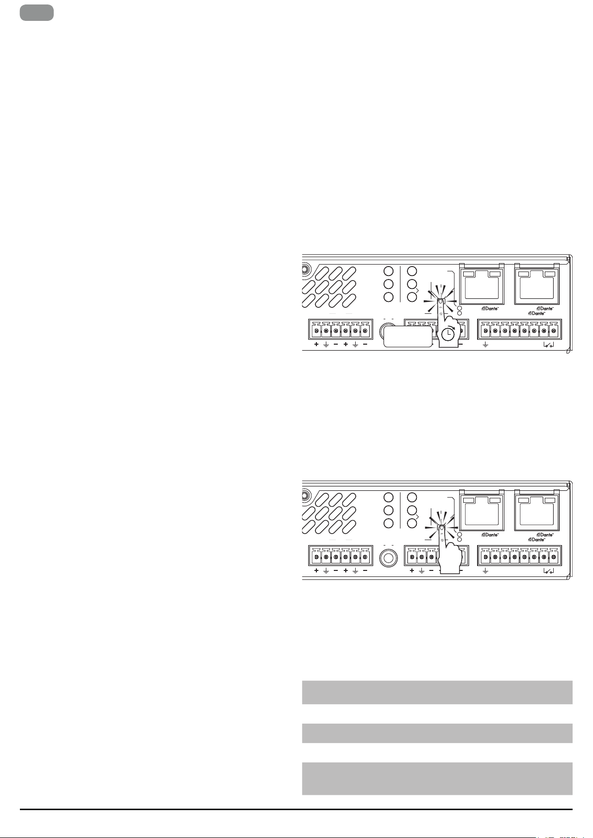
Note! Automac conguraon is only possible when the amplier is in its
factory default mode. Factory default is indicated by 5 seconds long blinks
of the 70V and 100V LEDs. In order to restore Mezzo's factory default
mode, press and hold the mode buon on the rear panel for 10 s.
Step 1 – Calibrate
SWITCHED
70V
25V
100V
IN2 1
CAL
3s
6s
CTRL
CTRL +CTRL +
I4 I3 I2 I1 5V
4 IN 3
STATUS
NETWORK
SIGNAL
2 IN 1
-10 dBV
Press the mode buon unl it fast blinks twice aer 2 s, release it
within 2 s aer it has blinked. This will trigger an automac impedance
measurement taking 1 s per channel. This will be made at a level that is
high enough to properly measure an 8 ohm loudspeaker. If the impedance
is higher the measurement might be deemed to be too noisy and it will
then repeat itself automacally. Please note that it may generate an SPL
exceeding 95 dB if the loudspeakers are sensive enough.
The impedance measurement will automacally set warning thresholds
monitoring change. It will also set the limiters so that the channel can
play as loud as the design and model allows, without distoron.
Step 2 - Select the maximum voltage
SWITCHED
70V
25V
100V
IN2 1
CAL
3s
6s
CTRL
CTRL +CTRL +
I4 I3 I2 I1 5V
4 IN 3
STATUS
NETWORK
SIGNAL
2 IN 1
-10 dBV
No channel will ever be assigned limiters that exceed the power
of the power supply. The main reason for selecng the maximum
voltage is to ensure that 25/70/100V loudspeakers will get the
power selected on their tapping if a channel is using less power
than it can deliver.
If the applicaon is 25V or 70V, then there is a risk that the limiters
get set too high if the connected load isn’t requiring full power. This
is xed with short presses on the mode buon unl it shows the
desired maximum voltage:
70V
100V
LED
Max Peak
LED
Voltage
Unlit Lit 141.4 V
Lit Unlit 100 V
Lit Lit 35.4 V
Unlit Unlit Custom Sengs
peak
peak
peak
Max RMS
Voltage
100 V
rms
70.7 V
rms
25 V
rms
Descripon
Also works in mixed 100V and low
impedance conguraons
Also works in mixed 70V and low
impedance conguraons
Also works in mixed 70V and low
impedance conguraons
This can’t be selected on the rear panel.
The limiters have been set manually
in the soware and can’t be changed
without a reset to factory defaults
4 | T Series
Page 5
Step 3 - Select the Ethernet mode of operaon (AD models)
STATUS
NETWORK
SIGNAL
SWITCHED
70V
100V
25V
CAL
6s
3s
CTRL +CTRL +
CTRL
I4 I3 I2 I1 5V
-10 dBV
4 IN 3
2 IN 1
OUT4 3
EN
SWITCHED
70V
25V
100V
5 seconds
CAL
3s
IN2 1
6s
CTRL
CTRL +CTRL +
I4 I3 I2 I1 5V
4 IN 3
STATUS
NETWORK
SIGNAL
2 IN 1
-10 dBV
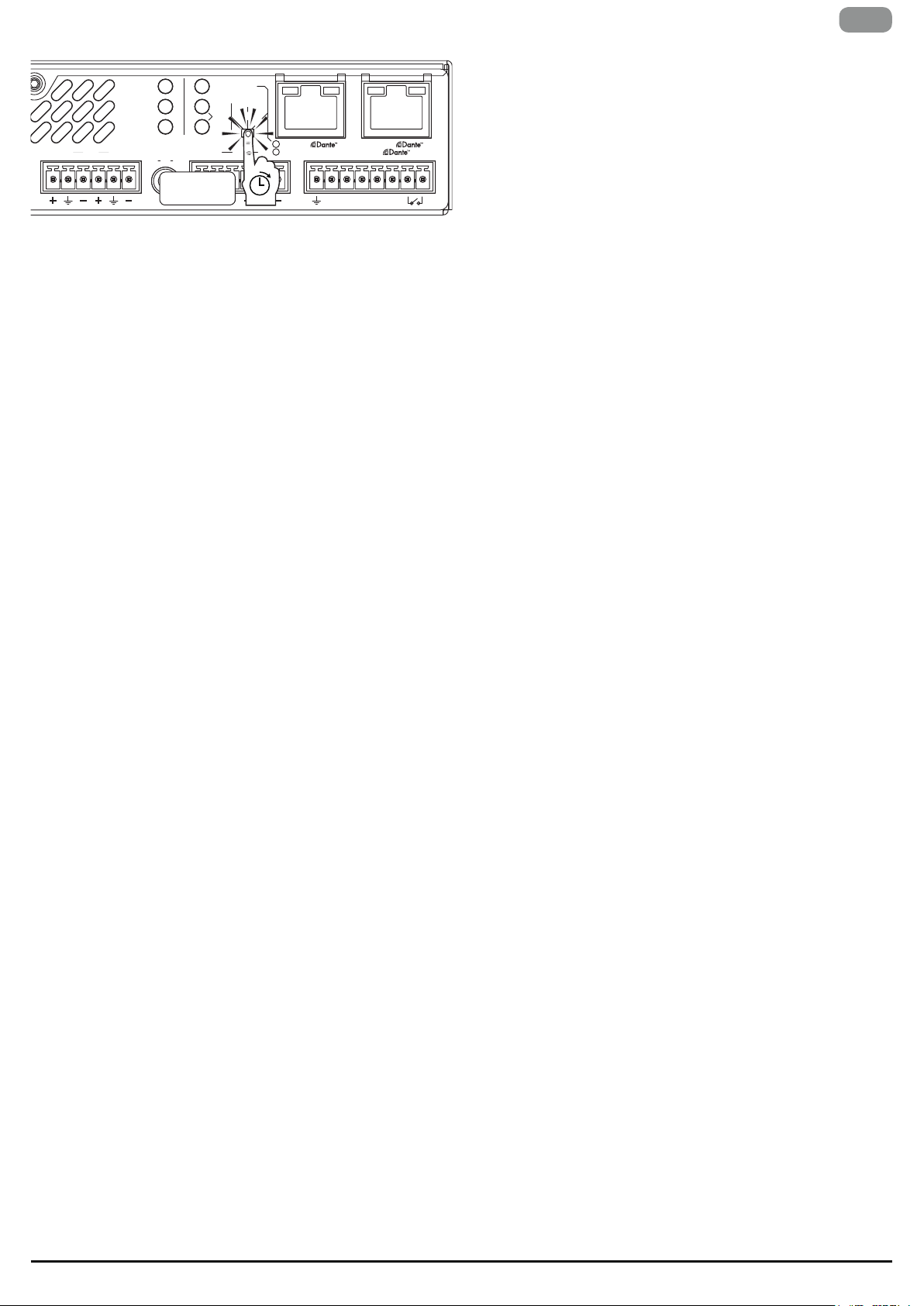
Press the mode buon unl it fast blinks (3 mes) aer 5 s, release
it within 2 s aer it has blinked. This will reset the amplier to autoIP and it will toggle the Ethernet mode and update the “Switched”
indicator:
• Unlit: This is the default “split mode”. The internal Ethernet
switch is disabled => the two ports are not connected and the
right port is then internally assigned for Dante/AES67. The le
port is only for control/monitoring.
• Lit: The internal Ethernet switch is enabled => the two ports are
connected and will both work for Dante and control/monitoring.
It means that you only need to connect with one cable for control
and audio. It also means that the product can be inserted in a
daisy chain of other Gigabit Ethernet products as long as there is
enough bandwidth.
Step 4 - Roung and control via GPI
Dante/AES67 (AD models)
Dante &/ AES67 is enabled and it has priority over the corresponding
analog input if there is an audio signal coming over the network.
This could be congured in the Dante Controller or in a third party
plug-in.
4 Channel models
The analog 1 is always a mix on the unbalanced and the balanced
analog 1; same with analog 2. The unbalanced input will get a 6 dB
boost so that normal unbalanced sources will deliver enough level
to drive the amplier to full power.
Otherwise the amplier will have straight 4 in 4 out roung and the
4 GPI inputs can be used with a 10kohm passive pot to aenuate
the levels. If a dierent roung or a dierent funconality of the
GPI pins is desired, then the soware needs to be used redene
the funconality of the GPI pins. Please look at the Advanced
conguraon (with soware) instead.
2 Channel models
The default here is that
• Whatever signal is delivered to output 1 is also delivered to
output 3 (but without the highpass lter). The level of these
outputs can be aenuated with GPI1.
• Whatever signal is delivered to output 2 is also delivered to
output 4. The level of these outputs can be aenuated with GPI2.
Inputs 1 and 3 are mixed. Inputs 2 and 4 are mixed. This means
that a balanced or unbalanced source can be used. It’s possible to
defeat this mixing by connecng GPI3 to GND. When this is done
GPI4 denes which input signal pair is used with an external contact
closure between GPI4 and GND. Open → the balanced inputs are
used; Closed → the unbalanced inputs are used.
T Series | 5
Page 6
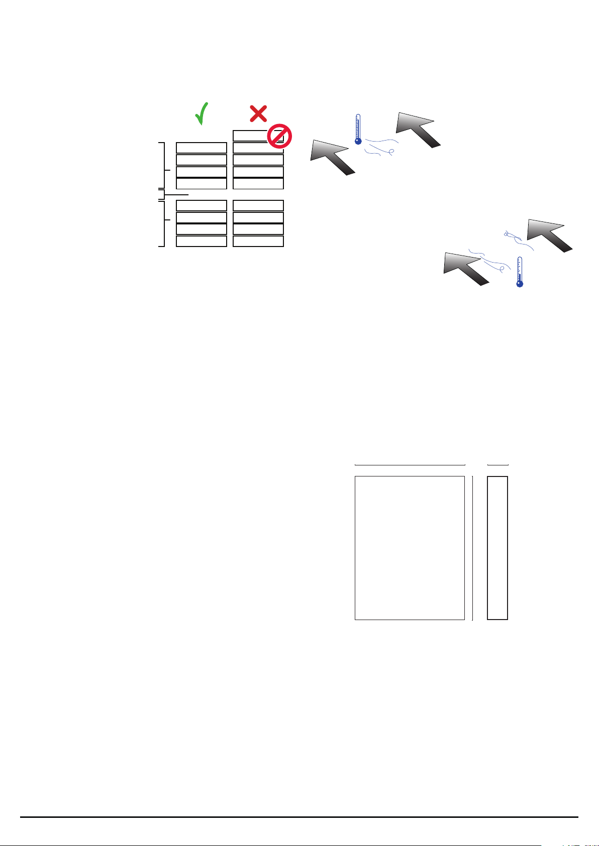
Locaon Cooling
1 RU
4 4
3 3
2 2
1 1
1 RU
4 4
3 3
2 2
1 1
5
1 RU
Dimensions
210 mm
8.3 in
40 mm
1.5 in
10.8 in
275 mm
Page 7
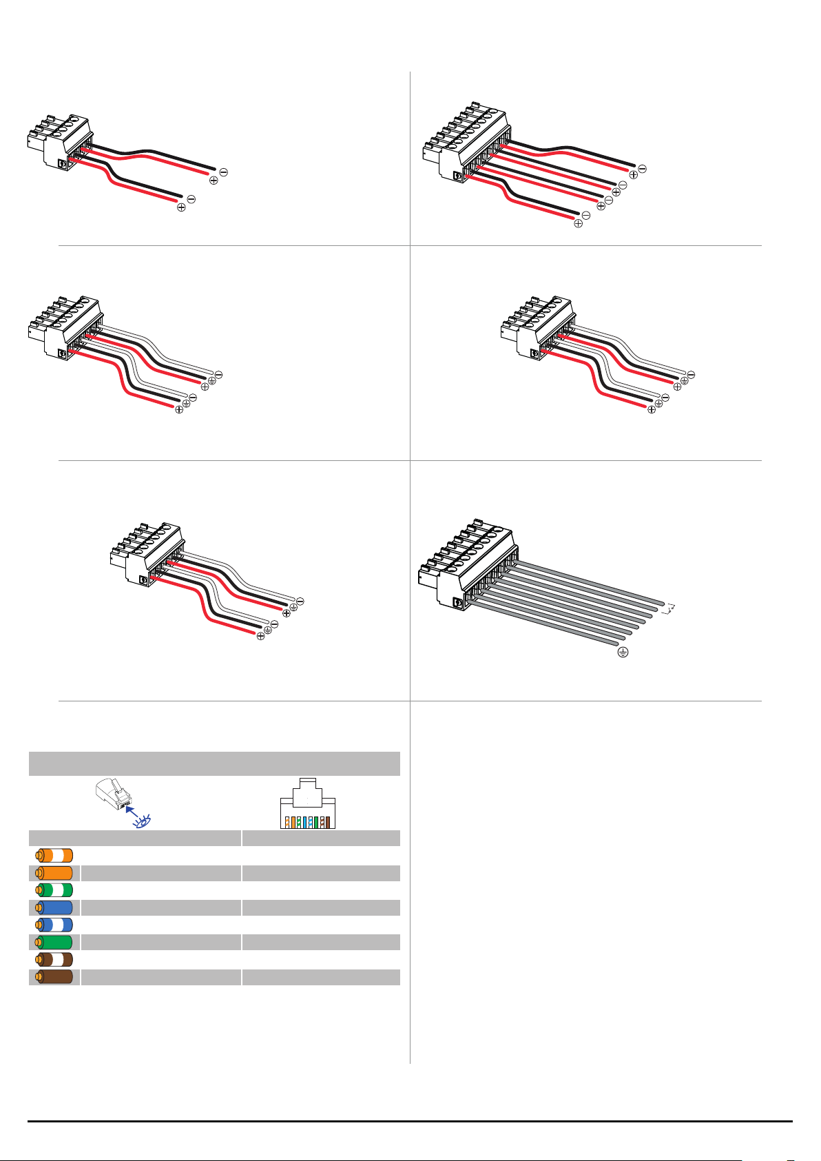
Pinouts
Outputs (2 Channel Versions)
Ch 1
Ch 2
CH4 - CH3 Balanced Inputs
Ch 3
Ch 4
Outputs (4 Channel Versions)
Ch 1
Ch 2
Ch 3
Ch 4
CH2 - CH1 Balanced Inputs (4 Channel Version)
Ch 3
Ch 4
CH4 - CH3 Line Level Outputs (2 Channel Version) GPI
Ch 3
Ch 4
Network Connector RJ45 pinout
1 2 3 4 5 6 7 8
Color code (TIA/EIA-568-B) Pin
ORANGE / WHITE 1
ORANGE 2
GREEN / WHITE 3
BLUE 4
BLUE / WHITE 5
GREEN
BROWN / WHITE 7
BROWN 8
6
5V
I1
I2
I3
I4
Page 8
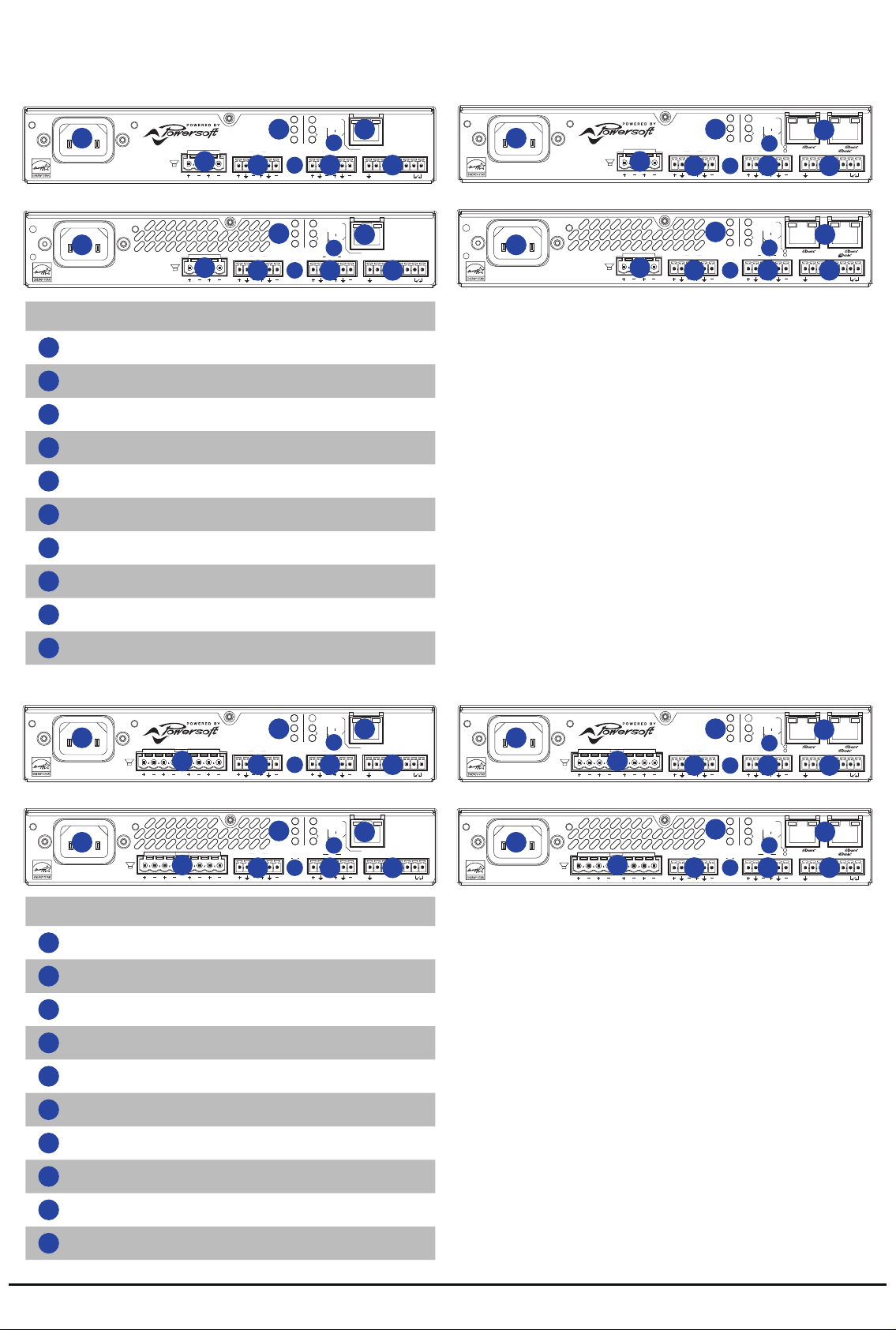
Rear Panels
STATUS
NETWORK
SIGNAL
70V
100V
25V
CAL
6s
3s
I4 I3 I2 I1 5V
-10 dBV
4 IN 3
MAINS
2 1
2 IN 1
OUT4 3
MEZZO 602 A
ETH
RESET
STATUS
NETWORK
SIGNAL
70V
100V
25V
CAL
6s
3s
I4 I3 I2 I1 5V
-10 dBV
4 IN 3
MAINS
2 1
2 IN 1
OUT4 3
MEZZO 602 A
STATUS
NETWORK
SIGNAL
70V
100V
25V
CAL
6s
3s
I4 I3 I2 I1 5V
-10 dBV
4 IN 3
MAINS
2 1
2 IN 1
ETH
OUT4 3
RESET
ETH
RESET
ETH
RESET
MEZZO 322 A
STATUS
NETWORK
SIGNAL
70V
100V
25V
CAL
6s
3s
I4 I3 I2 I1 5V
IN2 1
-10 dBV
4 IN 3
MAINS
4 3 2 1
2 IN 1
MEZZO 604 A
STATUS
NETWORK
SIGNAL
70V
100V
25V
CAL
6s
3s
I4 I3 I2 I1 5V
-10 dBV
4 IN 3
MAINS
2 1
2 IN 1
OUT4 3
MEZZO 602 A
ETH
RESET
STATUS
NETWORK
SIGNAL
SWITCHED
70V
100V
25V
CAL
6s
3s
CTRL +CTRL +
CTRL
I4 I3 I2 I1 5V
-10 dBV
4 IN 3
MAINS
2 1
2 IN 1
OUT4 3
MEZZO 602 AD
STATUS
NETWORK
SIGNAL
70V
100V
25V
CAL
6s
3s
I4 I3 I2 I1 5V
-10 dBV
4 IN 3
MAINS
2 1
2 IN 1
OUT4 3
MEZZO 322 AD
SWITCHED
CTRL +CTRL +
CTRL
Mezzo 322 A
1
MAINS
MEZZO 322 A
STATUS
NETWORK
7 7
SIGNAL
4 IN 3
2 2
2 1
3
2 IN 1
-10 dBV
RESET
CAL
70V
9
3s
25V
6s
100V
8
ETH
OUT4 3
4
5
6
I4 I3 I2 I1 5V
Mezzo 322 AD
1
MAINS
MEZZO 322 AD
Mezzo 602 A Mezzo 602 AD
STATUS
NETWORK
7
1 1
MAINS
MEZZO 602 A
2 2
2 1
SIGNAL
4 IN 3
3
2 IN 1
-10 dBV
RESET
CAL
70V
9
3s
25V
6s
100V
8
ETH
OUT4 3
4
5
6
I4 I3 I2 I1 5V
MAINS
MEZZO 602 AD
Rear panel - 2 Channel
1
AC Mains Connector / IEC 10A
2
CH2 -CH1 Outputs
3
CH4 - CH3 Balanced In puts
4
CH2 - CH1 Unbalanced Inputs
5
CH4 -CH3 Line Level Balanced Outputs
6
GPI
7
Amplier State LEDs
2 1
2 1
4 IN 3
3
4 IN 3
3
STATUS
NETWORK
SIGNAL
STATUS
NETWORK
7
SIGNAL
2 IN 1
-10 dBV
2 IN 1
-10 dBV
SWITCHED
CAL
70V
25V
100V
8
OUT4 3
4
5
SWITCHED
CAL
70V
25V
100V
8
OUT4 3
4
5
10
3s
6s
3s
6s
CTRL
CTRL
CTRL +CTRL +
6
I4 I3 I2 I1 5V
10
CTRL +CTRL +
6
I4 I3 I2 I1 5V
8
Load seng LEDs
9
RJ45 Fast Ethernet connector (Mezzo A Version)
10
2 X RJ45 Fast Ethernet connector (Mezzo AD Version)
Mezzo 324 A
STATUS
NETWORK
7 7
1
MAINS
MEZZO 324 A
2 2
4 3 2 1
4 IN 3
3
SIGNAL
2 IN 1
-10 dBV
4
Mezzo 604 A
STATUS
NETWORK
7
1 1
MAINS
MEZZO 604 A
2 2
4 3 2 1
4 IN 3
3
SIGNAL
2 IN 1
-10 dBV
4
Rear panel - 4 Channel
1
AC Mains Connector / IEC 10A
2
CH4 - CH3 - CH2 - CH1 Outputs
3
CH4 - CH3 Balanced Inputs
Mezzo 324 AD
RESET
CAL
70V
9
3s
25V
6s
100V
8
ETH
IN2 1
5
6
I4 I3 I2 I1 5V
1
MAINS
MEZZO 324 AD
4 3 2 1
NETWORK
4 IN 3
3
STATUS
SIGNAL
2 IN 1
-10 dBV
SWITCHED
CAL
70V
25V
100V
8
IN2 1
4
5
10
3s
6s
CTRL
CTRL +CTRL +
6
I4 I3 I2 I1 5V
Mezzo 604 AD
SWITCHED
4 IN 3
3
STATUS
NETWORK
7
SIGNAL
2 IN 1
-10 dBV
CAL
70V
25V
100V
8
IN2 1
4
5
10
3s
6s
CTRL
CTRL +CTRL +
6
I4 I3 I2 I1 5V
RESET
CAL
70V
9
3s
25V
6s
100V
8
ETH
IN2 1
5
6
I4 I3 I2 I1 5V
MAINS
MEZZO 604 AD
4 3 2 1
4
CH2 - CH1 Unbalanced Inputs
5
CH2 -CH1 Balanced Inputs
6
GPI
7
Amplier State LEDs
8
Load seng LEDs
9
RJ45 Fast Ethernet connector (Mezzo A Version)
10
2 X RJ45 Fast Ethernet connector (Mezzo AD Version)
Page 9

Page 10

DRIVING HUMAN AUDIO EXPERIENCE
POWERSOFT S.P.A.
Via E. Con, 5 - Scandicci (FI) 50018 - Italy
support@powerso.com
+39 055 73 50 230
+39 055 73 56 235
POWERSOFT.COM
 Loading...