

Page 1

APPLICATION NOTES
LIMITERS: BASIC CONCEPTS AND OPERATIONS
Page 2

1
DO000274.00 REV.00
LIMITERS: BASIC CONCEPTS AND OPERATIONS
1. Introducon
The main purpose of this applicaon note is to provide beer understanding on how to use the
dierent types of limiters available in Powerso ampliers. This document is applicable to the
following product lines: X series, T series, Oo/Quaro/Due Canali DSP+D series, Mezzo series and
Loto DSP.
Choosing the correct limiter is not an easy task and many aspects need to be considered; e.g.: it can
be dicult to decide thresholds and me constants to obtain the correct balance between protecon
and sound quality, hence every decision should be based on a wider knowledge of the component to
limit.
Liming may be considered an “art” and many dierent approaches and philosophies can be
followed. For this reason, this guideline intends to simply provide a starng point on limiter
parameters and how to handle them with Powerso devices.
NOTE: Powerso is not responsible for misuse of the informaon contained in this document and/or
any potenal loudspeaker or other damages derived from incorrect limiter sengs. This document
serves as a general guideline and is subject to the context in which it is applied.
Page 3
2
DO000274.00 REV.00
2. Liming, speaker damage and power compression
The liming process in sound reinforcement is a way to protect loudspeakers from accidental damage;
therefore, limiters are a safeguard against excessive signal peaks and/or signal long term average
power.
Bear in mind that liming does not only prevent occasional damage, but it rst and foremost
guarantees a long loudspeaker life.
Speaker limiter designers do not usually concentrate on colouring sound, but rather on speaker
protecon. Typical applicaons in the audio chain are:
• Controlling the energy of a signal.
• Controlling the peak levels of a signal.
• Reducing the dynamic range of a signal.
Remember that in sound reinforcement you are dealing with power signal (that means high voltage
and currents), so the target with limiters is to protect the drivers from the two main causes of damage:
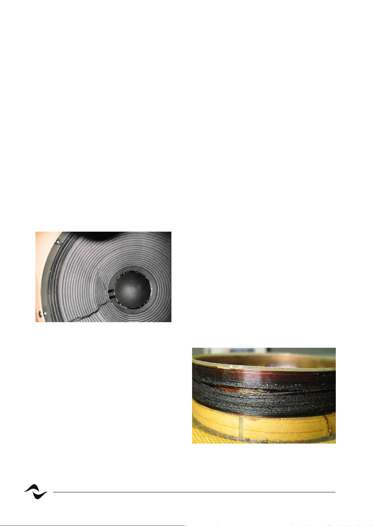
• Over-excursion: An impulsive signal can reach the
speakers and cause damage due to over-excursion of
the voice coil that is driven out of the mechanical
limit. This can damage the diaphragm deforming or
breaking it.
Figure 1 – Broken woofer
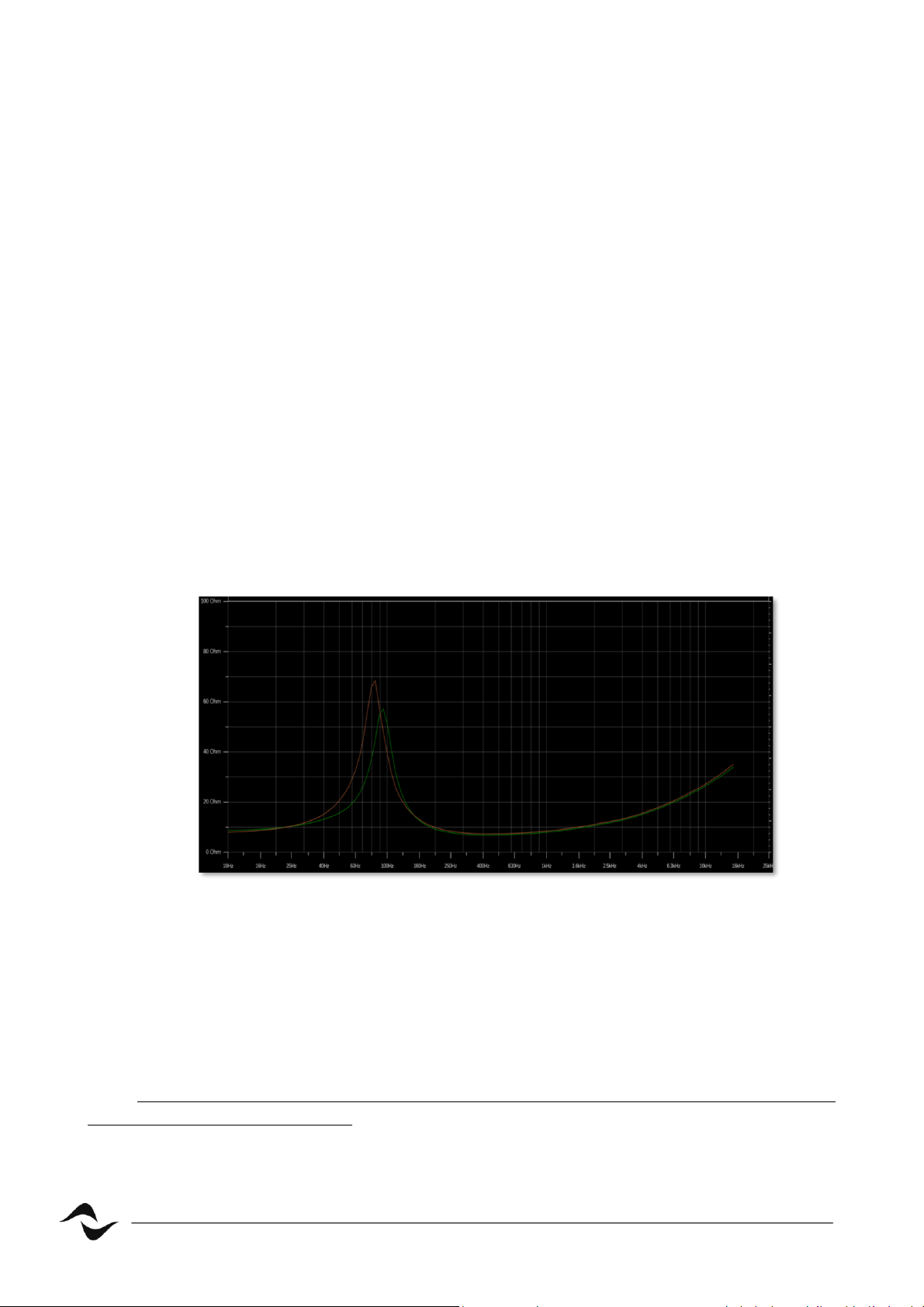
• Over-heang: Delivering high power for too
much me may lead to overheang of the
voice coil copper, the coil former, the
magnet, the suspensions and the cone
itself. Another eect is power compression,
more noceable in low frequency speakers.
When there is power compression there is
an increase of the impedance and a
decrease of power with the result of less
perceived loudness!
Figure 2 – Burned coil
Page 4
3
DO000274.00 REV.00
3. Limiter type: RMS, Peak and Clip
To avoid mechanical and temperature related damages two kinds of limiters can be used:
• RMS limiter: Protects speakers against thermal damage when excessive power is applied for
extended periods of me, resulng in overheang and eventually burning.
Designers should be aware of the maximum long-term power safely applicable to speakers
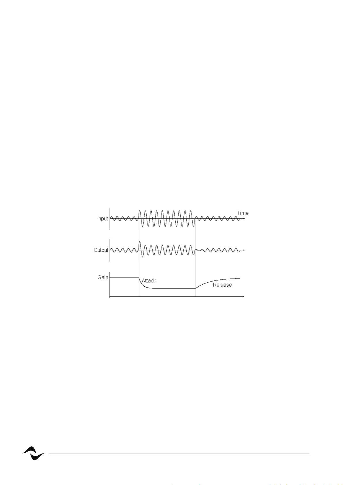
(AES power rang). An interesng approach to RMS liming is one that uses coil temperature
control looking at how the peak in the impedance curve changes when the speaker starts
heang.
In gure 3 we can see the relaonship between the temperature and impedance curves: the
green curve is the curve measured when the speaker is at 26°C, meaning it is cold. The orange
curve is when the temperature increases to 38°C. We can noce that when the speaker starts
heang up the impedance peak will become higher in value and will shi slightly in frequency.
Therefore, being able to monitor the impedance changes in real-me will allow us to save our
loudspeaker.
A complete knowledge of the driver’s limits allows to keep the temperature level in a safe
interval not only to avoid damage but to maintain the speaker in a “linear” zone avoiding
power compression.
Figure 3 – Live impedance curves
• Peak and limiter: Protect against mechanical damages.
Designers should set this limiter parameters as a funcon of both the maximum displacement
(X
MAX
) of the diaphragm and the speaker maximum tolerated voltage.
NOTE: Relying on peak liming only for speaker protecon can sll lead to excessive long-term average
power and consequenal damages.
Page 5
4
DO000274.00 REV.00
4. Limiter parameters
4.1 Threshold
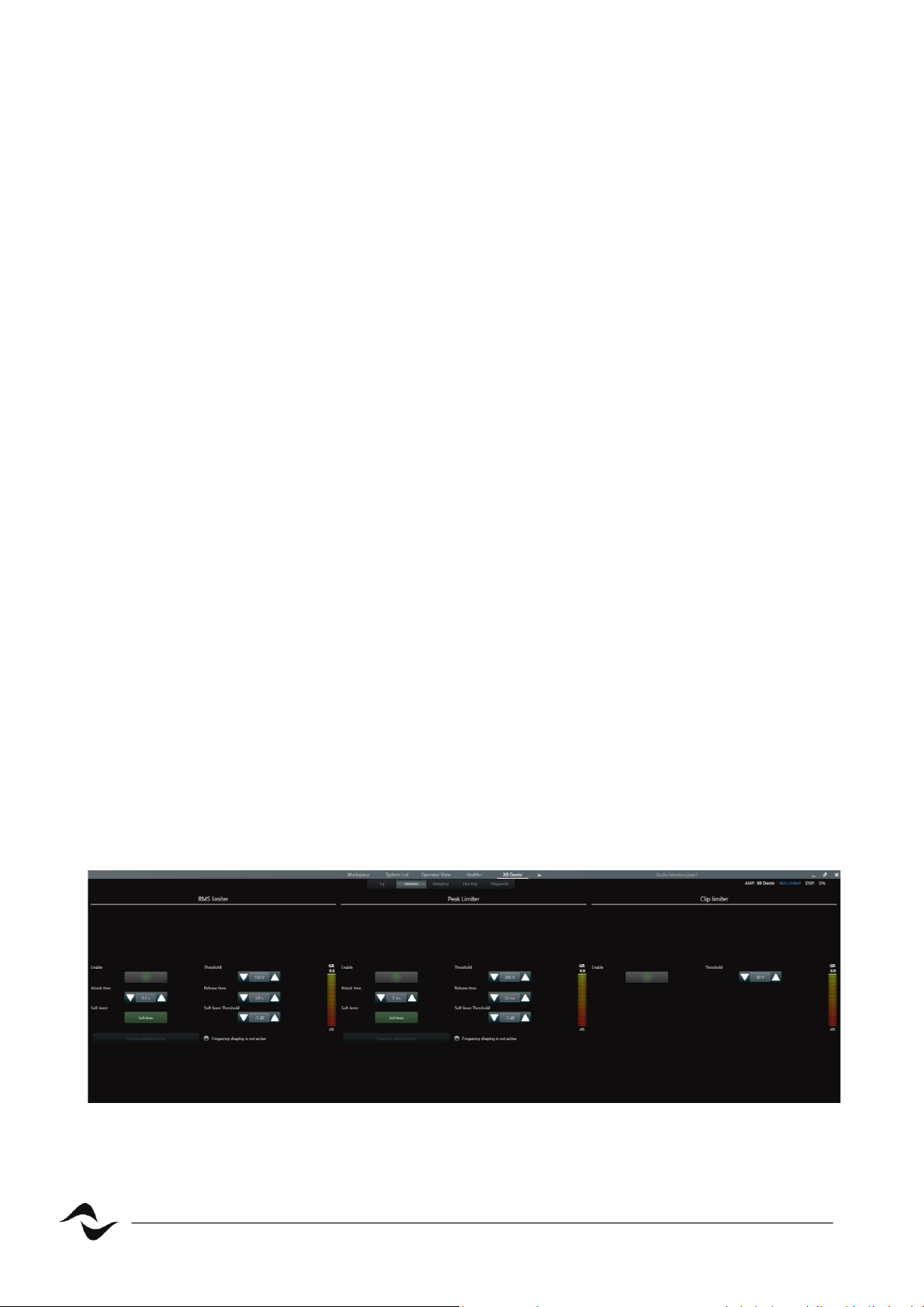
When the input signal level exceeds the threshold, the limiter starts to reduce the input gain.
Gain is reduced of an amount equal to the overshoot of the input signal with respect to the threshold.
The threshold value is expressed in Volt because it depends on the power of the loudspeaker and its
impedance.
4.2 Aack me
It is the me the limiter takes to get 70% of the total required reducon aer exceeding the threshold
level. In applicaons where we want to avoid speaker damage, the longer the aack me, the higher
the risk of damaging the equipment. However, sengs with a too fast aack me can generate
distorons or a deep modicaon to the transient of the signal, especially with percussive sounds,
resulng in poor perceived sound quality.
Typically, a good compromise is to set an aack me no longer than the lowest frequency you need
to protect (i.e. 1 ms for an HF driver with X-over at 1kHz octave band).
Figure 4 – Limiter acng on an audio signal
4.3 Release me
It is the me that the gain takes to go from the maximum reducon to 30% of reducon. In general,
the release me, has to be adequate to avoid a pumping eect and protect the speaker. The release
me can be set between 1 to 32 mes the aack me.
4.4 So knee
A so knee slowly increases the compression rao as the level increases, this way the changing from
un-compressed to compressed sound is less audible. This value in Powerso limiters is expressed in
dB below the threshold.
Page 6
5
DO000274.00 REV.00
5. How Powerso limiters work
5.1 RMS Limiter
The RMS limiter is intended to prevent burning the driver’s voice coil, while at the same me
exploing their maximum performance. The RMS limiter should not be engaged at normal working
levels since a common musical signal has very high peaks, but a rather small average level.
5.2 Peak limiter
The peak limiter avoids potenally dangerous displacement of the cone (larger excursion with respect
to the allowed values), and it is based only on the quanty of signal that is sent through that channel.
Peak limiters, as well as RMS and Clip limiters, are independent from the number of parallel wired
speakers: you can use the power and impedance of a single speaker or the power and impedance of
the parallel circuit, the given result will be the same.
Pushing into a peak limiter can reduce the crest factor, thus “squashing” the dynamics of the original
signal. For most applicaons, 3 to 9 dB of gain reducon is usually suggested.
5.3 Clip limiter
The Powerso clip limiter is a “brickwall” limiter that blocks the driving signal, not allowing it to exceed
the threshold. This limiter has a xed aack me of 0.3 ms with a lookahead of 0.3 ms that allows to
ancipate peaks before they occur and therefore with the benet of less distoron by not having a
hard clip. Clip limiters are very fast and are the last safety tool that can be used to avoid loudspeaker
damage. To achieve the best result in quality and performance, it is suggested a gain reducon
between 0 and 3 dB and to engage also Peak and Rms limiters.
Figure 5 – Limiters (basic) in ArmonìaPlus.
Page 7
6
DO000274.00 REV.00
6. How to calculate limiter values
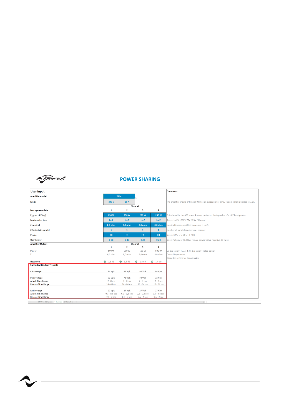
To calculate Voltage thresholds, aack, and release me for the three basic limiters available in
ArmonìaPlus, Powerso has developed a tool called the Power Sharing Tool.
In this tool there is a dedicated secon called “Suggested Limiters threshold” that can be used as a
safety starng point while working with limiters.
Simply add the loudspeaker’s AES power, the nominal impedance and select its prole (or the way of
the loudspeaker). Once these values are specied the tool will calculate and suggest a possible limiters
conguraon.
The tool provides calculaons for both Low-Z loudspeakers and Hi-Z lines (100V, 70V and 25V)
Remember that this is only the starng point, especially for a mul-way loudspeaker where it is always
suggested to analyse the behaviour of the ways with a musical or pseudo-musical signal.
In this way, tonality unbalances due to wide dierences in gain reducon between the transducers
can be avoided.
Figure 5 – Powerso Power Sharing tool limiters secon.
Page 8

7
DO000274.00 REV.00
7. Conclusions
Aer this basic analysis of Powerso limiters we can focus on two key points: the rst one is that all
Powerso limiters are made to protect the loudspeaker, so it is best pracce to have them always
enabled.
The second one concerns the sound quality and good system design: the best performances in audio
quality are achieved when, as menoned previously, RMS limiters are able to do the heaviest part of
the job in terms of gain reducon, then Peak limiters to control transients and Clip limiters as a nal
safety point.
By following this simple workow, you will achieve the best audio quality from your system, ensuring
its long lifespan.
Page 9

8
DO000274.00 REV.00
Document Title: LIMITERS: BASIC CONCEPTS AND OPERATIONS
Reference: DO000274.00 REV.00
Powerso S.p.A
Via E. Con, 5 - Scandicci (Fi) 50018 - Italy
TELEPHONE: +39 055 7350230
General Enquires: info@powerso.it
Sales: sales@powerso.it
Applicaon & Technical Support: support.audio@powerso.com
Service & Maintenance: service@powerso.it
www.powerso.com
 Loading...