

Page 1

IpalMod
©2019 Powersoft
DO000129.03 R0
USER GUIDE
Keep this manual
for future reference
Page 2

DO000129_powersoft_IpalMod_uguide_en
Data are subject to change without notice.
For latest update please refer to the
online version available on www.powersoft-audio.com.
Page 3

IpalMod User Guide
Table of contents
1. Important safety instructions iii
2. Importantes instructions de sécurité iv
3. Instrucciones de seguridad importantes v
4. Importanti istruzioni di sicurezza vi
5. Regulatory information vii
6. Electrostatic Discharge (ESD) viii
7. IpalMod 1
7 : 1.Welcome 1
7 : 2.Unpacking & checking for shipping damage 1
7 : 3.Disposal of the packing material 1
7 : 4.Differential Pressure Control 1
7 : 4.1. Virtu al Transducer mode 1
7 : 4.2. Pr essur e mode 1
8. Thermal constrains 2
8 : 1.Heatsink performance 2
8 : 2.Suggested heatsink 3
9. Electromagnetic Compatibility (EMC) 4
9 : 1.AC MAIN filter 4
9 : 2.Earth connection 4
9 : 3.Cabling 4
9 : 4.Ferrite cores 4
9 : 5.Chassis shielding 4
10. Mechanical drawings 5
11. Connections 7
11 : 1.Interface board: bill of connectors 7
11 : 2.RS-485 inter face 7
11 : 3.Control board: bill of connectors 7
11 : 4.Amp module: bill of connectors 8
11 : 4.1. CN11 pinout 8
11 : 4.2. CN17 pinout 8
11 : 4.3. CN14 pinout 9
11 : 4.4. CN16 pinout 9
11 : 4.5. CN10, CN19, CN20 pinout 9
11 : 4.6. CN2 pinou t 9
11 : 5.IpalMod without DPC interface board 11
11 : 6.Installing an optional DSP SIMM board 11
12. LED chart 12
12 : 1.Main PCB LED chart 12
12 : 3.SIMM board LED chart 12
12 : 2.Interface board LED chart 12
13. Pressure sensor 13
14. Power Control Manager 14
14 : 1.Connect and discover the system 14
14 : 1.1. Automat ic d iscover y 15
14 : 1.2. Manual disco ver y 15
15. Setting the Differential Pressure Control 16
15 : 1.Global settings 16
Table of contents | i
Page 4

15 : 1.1. Input G ain 16
15 : 1.2. Polarity 16
15 : 1.3. Delay 16
15 : 1.4. Parametric e qualize r 16
15 : 2.Operating modes 17
15 : 2.1. P ress ure Model Mo de 17
15 : 2.2. Vir tua l Sp eaker Mode 17
15 : 3.Thiele/Small parameters 18
15 : 3.1. Calculated p aram eter s 18
15 : 4.Advanced parameters 18
15 : 4.1. DSP sett ing p aram eter s 18
15 : 5.More about DPC 19
15 : 6.Metering 20
15 : 6.1. LEDs 20
15 : 6.2. Meter strips 20
16. Hardware protections 21
15 : 7.Power supply protections 21
15 : 7.1. Primary AC mains overcurrent protection 21
15 : 7.2. Primary AC mains overvoltage protection 21
15 : 7. 3. Pri mar y t herma l pr ote ctio n 21
15 : 8.Amplifier protections 21
15 : 8.1. Auxiliary power pro tect ions 21
17. Support and warranty 22
17 : 1.Service 22
17 : 2.Warrant y 22
17 : 2.1. Return of G ood s 22
17 : 2.2. Repair or replac ement 22
17 : 2.3. Cost and responsibility of transport 22
17 : 3.Assistance 22
ii | IpalMod | User guide
Page 5

Important safety instructions
This amplifier module is intended to be installed inside
other devices and must be checked in the final product.
EXPLANATIONS OF GRAPHICAL SYMBOLS
1
CAUTION
RISK OF ELECTRICK SHOCK
DO NOT OPEN
The triangle with the lightning bolt is used to alert the
user to the risk of electric shock.
The triangle with the exclamation point is used to
alert the user to important operating or maintenance
instructions.
The CE-mark indicates the compliance with the low
voltage and electromagnetic compatibility.
Symbol for earth/ground connection.
Symbol for conformity with Directive 2002/96/EC
and Directive 2003/108/EC of the European
Parliament on waste electrical and electronic equipment (WEEE).
Symbol for electrostatic discharge sensitive devices.
1. Read these instructions.
2. Keep these instructions.
3. Heed all warnings.
4. Follow all instructions.
5. Do not use this equipment near water.
6. Do not block any ventilation openings. Install in accordance with
Powersoft’s instructions.
7. Do not install near any heat sources such as radiators, heat registers, stover or other apparatus that produce heat.
8. Do not defeat the safety purpose of the polarized or groundingtype plug.
9. Only use attachments/accessories specified by Powersoft.
10. Refer all servicing to qualified service personnel. Servicing is
required when the apparatus has been damaged in any way, such
as power-supply cord or plug is damaged, liquid has been spilled
or objects have fallen into the apparatus, the apparatus has been
exposed to rain or moisture, does not operate normally, or has
been dropped.
WARNING: TO REDUCE THE RISK OF ELECTRIC SHOCK, DO
NOT ATTEMPT TO OPEN ANY PART OF THE UNIT. NO USERSERVICEABLE PARTS INSIDE. REFER SERVICING TO QUALIFIED
SERVICE PERSONNEL.
DO NOT EXPOSE THIS EQUIPMENT TO RAIN OR MOISTURE,
DRIPPING OR SPLASHING LIQUIDS. OBJECTS FILLED WITH
LIQUIDS, SUCH AS VASES, SHOULD NOT BE PLACED ON THIS
APPARATUS.
Important safety instructions | iii
Page 6

Importantes instructions de sécurité
Ce module d’amplification est destiné à être
installé à l’intérieur d’autres dispositifs et doit
donc être contrôlé sur le produit fini.
EXPLICATION DES SYMBOLES GRAPHIQUES
2
AVIS
RISQUES D’ÉLECTROCUTION
NE PAS OUVRIR
La triangle avec le symbol du foudre est employée
pour alerter l’utilisateur au risque de décharge électrique.
Le triangle avec un point d’exclamation est employée
pour alerter l’utilisateur d’instruction importantes
pour lors opérations de maintenance.
Le marquage CE indique la conformité à la directive de
basse tension et la compatibilité électromagnétique.
Symbole pour la connexion à la terre.
Symbole pour la conformité al la Directive 2002/96/
EC et la Directive 2003/108/EC du Parlement
Européen sur les équipements électriques et électroniques (WEEE).
Symbole pour les appareils sensibles aux décharges
électrostatiques.
1. Lisez ces instructions.
2. Gardez ces instructions.
3. Tenez compte de toutes les mises en garde.
4. Suivez toutes les instructions.
5. N’utilisez pas cet amplificateur à proximité de l’eau.
6. Assurez-vous d’une bonne ventilation de l’appareil. Installez en
accord avec les instructions préconisées par Powersoft.
7. N’installez pas l’appareil à proximité de sources de chaleur ou
d’autres appareils produisant de la chaleur.
8. Respectez le dispositif de mise à la terre de la prise secteur.
9. Utilisez uniquement les accroches et accessoires spécifiés par
Powersoft.
10. Confiez toute réparation à un technicien qualifié. L’intervention
d’un technicien est nécessaire dans les cas suivants : le cordon
d’alimentation ou la prise secteur sont endommagés, des corps
étrangers ou du liquide se sont introduits dans l’appareil, l’appareil
a été exposé à la pluie ou à l’humidité, l’appareil montre des
signes de dysfonctionnement ou est tombé.
MISE EN GARDE : AFIN DE RÉDUIRE LES RISQUES DE CHOC
ÉLECTRIQUE, N’ESSAYEZ PAS D’OUVRIR L’UNITÉ, MEME EN
PARTIE. AUCUNE PIÈCE A L’INTERIEUR NE PEUT ETRE CHANGÉE PAR
L’UTILISATEUR. LAISSEZ L’ENTRETIEN A UN PERSONNEL QUALIFIÉ.
iv | IpalMod | User guide
NE PAS EXPOSER CET APPAREIL A LA PLUIE OU A L’HUMIDITÉ,
AUX GOUTTES OU AUX ÉCLABOUSSURES. LES OBJETS
REMPLIS DE LIQUIDE, TELS QUE LES VASES, NE DOIVENT PAS ETRE
PLACÉS SUR CET APPAREIL.
Page 7

Instrucciones de seguridad importantes
Este módulo amplificador está diseñado para
ser instalado dentro de otros dispositivos y
debe verificarse en el producto final.
EXPLICACIÓN DE LOS SÍMBOLOS GRÁFICOS
3
PRECAUCIÓN
RIESGO DE CHOQUE ELÉCTRICO
NO ABRA LA UNIDAD
El triángulo con el símbolo de rayo eléctrico es usado para alertar al usuario de el riesgo de un choque
eléctrico.
El triángulo con el signo de admiración es usado
para alertar al usuario de instrucciones importantes
de operación o mantenimiento.
La marca CE indica el cumplimiento de la directiva
de bajo voltaje y de compatibilidad electromagnética.
Símbolo de la conexión a tierra.
Símbolo de conformidad con la Directiva 2002/96/
EC y Directiva 2003/108/EC del Parlamento Europeo
sobre los aparatos eléctricos y electrónicos (WEEE).
Símbolo para los dispositivos sensibles a descargas
electrostáticas.
1. Lea estas instrucciones.
2. Guarde estas instrucciones.
3. Preste atención a todas las advertencias.
4. Siga todas las instrucciones.
5. No use este aparato cerca del agua.
6. No bloquee las aberturas de ventilación. Realice la instalación de
acuerdo con las indicaciones de Powersoft.
7. No instale cerca ninguna fuente de calor como, por ejemplo,
radiadores, rejillas de calefacción, hornos u otros aparatos que
produzcan calor.
8. No elimine el diseño de seguridad del enchufe, ya sea del tipo polarizado o con conexión a tierra.
9. Use exclusivamente los dispositivos/accesorios indicados por
Powersoft.
10. El servicio técnico debe realizarlo siempre personal cualificado. Se
requerirá servicio de asistencia técnica cuando el aparato sufra
algún tipo de daño como, por ejemplo, que el cable de alimentación
o el enchufe estén dañados, que se haya derramado líquido o hayan
caído objetos dentro del aparato, que éste se haya expuesto a la lluvia o humedad, que no funcione normalmente o que se haya caído.
PRECAUCIÓN: PARA REDUCIR EL RIESGO DE DESCARGA
ELÉCTRICA, NO DESMONTE LA TAPA (NI EL PANEL TRASERO).
NO HAY PIEZAS REPARABLES POR EL USUARIO EN EL INTERIOR.
LLÉVELO A REPARAR A PERSONAL DE SERVICIO CUALIFICADO.
NO EXPONGA ESTE UNITAD A LA LLUVIA O LA HUMEDAD,
GOTEO O SALPICADURAS. NO COLOQUE OBJETOS LLENOS DE
LÍQUIDOS, TALES COMO VASIJAS, SOBRE EL APARATO.
Instrucciones de seguridad importantes | v
Page 8

Importanti istruzioni di sicurezza
Questo modulo amplificatore è destinato ad essere
installato dentro altri dispositivi e deve quindi
essere controllato nel prodotto finito.
SPIEGAZIONE DEI SIMBOLI GRAFICI
4
ATTENZIONE
RISCHIO DI SCOSSE
ELETTRICHE, NON APRIRE
Il triangolo con il lampo è utilizzato per avvisare
l’utente del rischio di scossa elettrica.
Il triangolo con il punto esclamativo è utilizzato per
avvisare l’utente di importanti istruzioni d’uso e manutenzione.
The CE-mark indicates the compliance with the low
voltage and electromagnetic compatibility.
Simbolo della connessine di terra.
Simbolo di conformità alla Direttiva 2002/96/CE e
alla Direttiva 2003/108/CE del Parlamento Europeo
sulle apparecchiature elettriche ed elettroniche
(RAEE).
Simbolo per le apparecchiature sensibili alle scariche
elettrostatiche
L’elettricità viene usata per svolgere molte funzioni utili, ma può anche
causare danni personali o agli oggetti se applicata in modo improprio.
Questo prodotto è stato progettato e realizzato con la massima attenzione alla sicurezza. Tuttavia, UN USO IMPROPRIO PUÒ PRODURRE
SCOSSE ELETTRICHE E/O INCENDI. Per evitare potenziali pericoli, osservare le seguenti istruzioni durante l’installazione, l’utilizzo e la pulizia
del prodotto. Per garantire la sicurezza e prolungare la vita utile del
monitor LCD, leggere attentamente le seguenti precauzioni prima di
usare il prodotto.
Importanti istruzioni di sicurezza
1. Leggere queste istruzioni.
2. Conservare le istruzioni.
3. Tenere conto di tutti gli avvisi.
4. Seguire tutte le istruzioni.
5. Non usare l'apparecchio in prossimità di acqua.
6. Non ostruire le prese di ventilazione. Installare secondo le indicazioni del produttore.
7. Non installare vicino a fonti di calore quali radiatori, bocchette
dell'aria calda, stufe o altri apparecchi (compresi gli amplificatori)
che producono calore.
8. Non compromettere la sicurezza delle spine polarizzate o con
messa a terra.
9. Usare solo accessori specificati dal produttore.
10. Ricorrere a personale qualificato per qualsiasi intervento. Tali
interventi sono necessari in caso di guasti dell'apparecchio
quali danneggiamento del cavo di alimentazione o della spina,
versamento di liquidi o caduta di oggetti nell'apparecchio, esposizione a pioggia o umidità o se l'apparecchio non funziona
normalmente o è caduto.
vi | IpalMod | User guide
ATTENZIONE: PER RIDURRE IL RISCHIO DI SCOSSE
ELETTRICHE, NON TENTARE DI APRIRE ALCUNA PARTE
DELL’UNITÀ. NON CI SONO PARTI INTERNE AD USO DELL’UTENTE.
RIVOLGERSI A PERSONALE QUALIFICATO PER L’ASSISTENZA.
NON ESPORRE QUESTO APPARECCHIO ALLA PIOGGIA,
UMIDITÀ O SOSTANZE LIQUIDE. OGGETTI PIENI DI LIQUIDI,
COME VASI, NON DEVONO ESSERE COLLOCATI SU QUESTO APPARATO.
Page 9

Regulatory information
5
FCC COMPLIANCE NOTICE
This device complies with part 15 of the FCC rules. Operation is subject
to the following two conditions: (1) This device may not cause harmful
interference, and (2) this device must accept any interference received,
including interference that may cause undesired operation.
CAUTION: Changes or modifications not expressly approved by the party
responsible for compliance could void the user’s authority to operate the
equipment.
NOTE: This equipment has been tested and found to comply with the
limits for a Class B digital device, pursuant to part 15 of the FCC Rules.
These limits are designed to provide reasonable protection against
harmful interference in a residential installation. This equipment generates, uses, and can radiate radio frequency energy and, if not installed
and used in accordance with the instruction manual, may cause harmful
interference to radio communications. However, there is no guarantee
that interference will not occur in a particular installation. If this equipment does cause harmful interference to radio or television reception,
which can be determined by turning the equipment off and on, the user
is encouraged to try to correct the interference by one or more of the
following measures:
Reorient or relocate the receiving antenna.
Increase the separation between the equipment and receiver.
Connect the equipment into an outlet on a circuit different from
that to which the receiver is connected.
Consult the dealer or an experienced radio/TV technician for help.
WEEE DIRECTIVE
If the time arises to throw away your product, please recycle all the components possible.
This symbol indicates that when the end-user wishes
to discard this product, it must be sent to separate collection facilities for recovery and recycling. By separating this product from other household-type waste, the
volume of waste sent to incinerators or land-fills will be
reduced and natural resources will thus be conserved.
EC DECLARATION OF CONFORMITY
Manufacturer:
Powersoft S.p.A.
via E. Conti 5
50018 Scandicci (Fi)
Italy
We declare that under our sole responsibility the products:
Model Name: IpalMod
Intended use: Professional Audio Amplifier Module
Are in conformity with the provisions of the following EC Directives,
including all amendments, and with national legislation implementing
these directives:
2006/95/EC Low Voltage Directive
2004/108/EC Electromagnetic Compatibility Directive
2002/95/CE RoHs Directive
The following armonized standards are applied:
EN 55103-1
EN 55014-1
EN 55022
EN 61000-3-2
EN 61000-3-3
EN 610 00-3-11
EN 61000-3-12
EN 55103-2
EN 61000-4-2
EN 61000-4-3
EN 61000-4-4
EN 61000-4-5
EN 61000-4-6
EN 610 00-4-11
EN 60065
Scandicci,
March 2002
The Waste Electrical and Electronic Equipment Directive (WEEE Directive)
aims to minimise the impact of electrical and electronic goods on the environment. Powersoft S.p.A. comply with the Directive 2002/96/EC and
2003/108/EC of the European Parliament on waste electrical finance the
cost of treatment and recovery of electronic equipment (WEEE) in order
to reduce the amount of WEEE that is being disposed of in land-fill site.
All of our products are marked with the WEEE symbol; this indicates that
this product must NOT be disposed of with other waste. Instead it is the
user’s responsibility to dispose of their waste electrical and electronic
equipment by handing it over to an approved reprocessor, or by returning it to Powesoft S.p.A. for reprocessing. For more information about
where you can send your waste equipment for recycling, please contact
Powesoft S.p.a. or one of your local distributors.
Luca Lastrucci
Managing Director
For compliance questions only: [email protected]
Regulatory information | vii
Page 10

Electrostatic Discharge (ESD)
Electrostatic discharge (ESD) is one of the most signicant factors leading to damage and failure of a wide variety
of electronic components.
Poor handling can cause internal damage, which is
invisible. This internal damage can then cause electrical
failure or reliability problems.
It is recommended that all workstations where
Electrostatic Discharge Sensitive devices (ESDS)
and assemblies are handled outside of full static protection
packaging (i.e. within static control areas) should be provided with some form of ground conductive or dissipative
ooring.
6
viii | IpalMod | User guide
Page 11

IpalMod User Guide User GuideUser Guide
7
7 : 1.Welcome
Congratulations on your purchase of the Powersoft
IpalMod module.
We know you are eager to use the IpalMod module, but
please take a moment to read this user’s manual and safety
instructions. In case you have any questions, please do not
hesitate to contact your dealer or Powersoft.
The IpalMod is a one channel amplier modules specically designed to drive high efciency low-impedance loudspeakers: it integrates the Powersoft’s patented Differential
Pressure Control technology that optimizes sonic performances of the amplier/transducer/cabinet/environment
system and is specically designed to fully exploit the
potential of the IPAL compatible transducers.
The IpalMod shows amazing gures in terms of both
output voltage (180 V
being able to drive even the most demanding applications
of self powered subwoofers and can be equipped with any
Powersoft or third-party DSP solution.
The new design of the power supply equipped with PFC,
reduces power consumption while enhancing reliability and
consistency in all operating conditions.
) and current capabilities (110 A
peak
peak
),
7 : 2.Unpacking & checking for shipping damage
Your Powersoft product has been completely tested and
inspected before leaving the factory. Carefully inspect the
shipping package before opening it, and then immediately
inspect your new product. If you nd any damage notify the
shipping company immediately.
7 : 3.Disposal of the packing material
The transport and protective packing has been selected
from materials which are environmentally friendly for disposal and can normally be recycled.
Rather than just throwing these materials away, please
ensure they are offered for recycling.
7 : 4.Differential Pressure Control
The Differential Pressure Control – DPC – is the core
technology of the Integrated Powered Adaptive Loudspeaker
system, also known as IPAL.
DPC makes IPAL systems efcient and reactive
®
DIFFERENTIAL
PRESSURE CONTROL
PATENTED
The differential pressure measurement, senses the difference of pressure between the front and the rear sides
of the radiating diaphragm and uses this information to
alter the behaviour of the transducer, according to the real
boundary conditions. Thanks to this innovative approach
to full boundary conditions feedback processing, the IPAL
system dramatically improves the electroacoustic efciency
in terms of high SPL and sonic performance of the sound
reinforcement system.
The IPAL system combines a high-efcient transducer
with a high-power switching mode amplier that embed a
fast and effective ZeroLatency™ DSP. The DSP performs
the double operation of both managing the loudspeaker
processing and taking care of the differential pressure control signal. IPAL establish a global feedback between the
electrical and the acoustic domains.
Thanks to the rich graphic user interface – GUI – it is
possible to weight and customize the feedback between the
electrical and the acoustic domains. Two operating modes
are available: Virtual Transducer and Pressure modes.
7 : 4.1. Virtual Transducer mode
The Virtual Transducer mode is based on the principle
of virtual loudspeaker emulation: once dened the desired
reference loudspeaker model (speaker designers can synthesize any desired driver using the GUI to set the ThieleSmall parameters) the IPAL achieves a very predictable and
stable electromechanical structure. The actual loudspeaker
will behave as the emulated virtual transducer, regardless to
aging, power compression and parameters drift, thanks to
the closed feedback loop that adaptively aligns the performance of the system to the desired ones.
to the environment condition, overcoming the
physical limitation of traditional sound reinforcement systems.
7 : 4.2. Pressure mode
The Pressure mode relies on the DPC making it possible
to match a specic target pressure response. Being the SPL
output of any acoustic signal derived from the relationship
between the pressure and the acoustical impedance, it’s
straightforward to use a direct measurement of such a
pressure signal to make the system track a reference target
pressure model. Benets in terms of predictability of the
system response and reduction of sensitivity from disturbing effects could be substantially appreciated.
IpalMod | 1
Page 12
Thermal constrains
8
This device must be correctly heatsinked for proper and
reliable operation.
The built-in fans and an appropriate external passive
heat sink guarantee by design thermal efciency and
reliability.
Proper heatsink planarity is strongly suggested to allow thermal transfer from the module’s bottom plate to the
heatsink; a thermal compound may be used, but it is not
strictly necessary.
In order to ensure proper ventilation of the module, reasonable spacing of at least 100 mm must be left between
the frame of the unit and any side component or surface of
the enclosure.
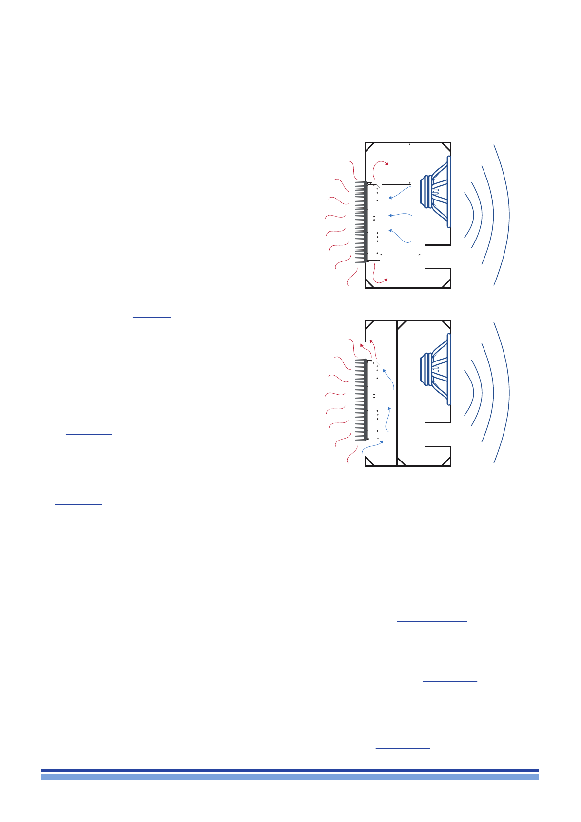
The module has been designed to t into a loudspeaker
cabinet: please refer to FIGURE 1 for proper module placing.
IN FIGURE 1 HEATSINK FINS ARE SET HORIZONTALLY
(WRONG!) ONLY FOR DESCRIPTIVE PURPOSE.
All conguration showed in FIGURE 1 are viable for
proper module placing and cooling. We suggest to position the module vertically with respect the ground in order
to take advantage of the chimney effect for ventilation and
heat dissipation.
In FIGURE 1.a the module and the loudspeakers share
the same room into the cabinet. This is the dafault placement solution: it allows good ventilation because of woofer
diaphragm movement and high air volume; be aware of
magnetic eld interaction: place the module far enough from
loudspeakers magnet in order to prevent fans blockage.
FIGURE 1.b shows the more efcient cooling congura-
tion, even if it is less effective against dust and moisture
that can get into the module. By allowing external air ow,
it is possible to reduce the ns width on the heatsink by
maintaining good cooling performances.
100 mm
MIN.
3.94 inch
Be aware of
magnetic leakage
a
b
FIGURE 1: Cooling solutions (for descriptive purpose the
heatsink fins are set in wrong direction);
a) Module and loudspeaker into the same chamber;
b) Module in a separate vented chamber.
8 : 1.Heatsink performance
Here we suggest a rule of thumb to calculate the thermal
resistance of the heatsink.
The absolute thermal resistance of the heatsink is the
temperature difference (kelvin or celsius) across it structure
when a unit of heat energy ows through it in unit time (watt).
For seek of simplicity, a heatsink with low thermal resistance
offers high heat dissipation, as well as a low electric resistance allows high current ow through a conductive wire.
In order to dene the maximum allowed thermal resistance for the heatsink let assume the following:
e as the amp module efciency
cf as the crest factor of the audio signal
W
as the peak power delivered by the module
max
T
as the highest ambient temperature
amb
T
as the highest operating temperature
mod
2 | IpalMod | User guide
The thermal resistance of the heatsink derives from the following formula:
T
- T
mod
Rth =
Dissipated power
The maximum dissipated power can be calculated as:
Dissipated power =
For example, stating an efciency of 80%, 6 dB crest factor
and 3400 W peak power, the dissipated heat is:
3400 (1 - 0.8)
4
amb
W
(1 - e)
max
cf
= 170 W
Page 13
Considering that thermal protection of the module (T
set at 75°C (167°F) on the bottom aluminium plate and stating an ambient temperature of 45 °C (113°F), the previous
example gives:
mod
) is
meaning that the temperature of the bottom plate is always
lower than 75°C if the heatsink has a thermal resistance better than 0.14°C/W (or 0.14 K/W) with ambient temperature
up to 45 °C.
75 - 45
170
= 0.14°C/W
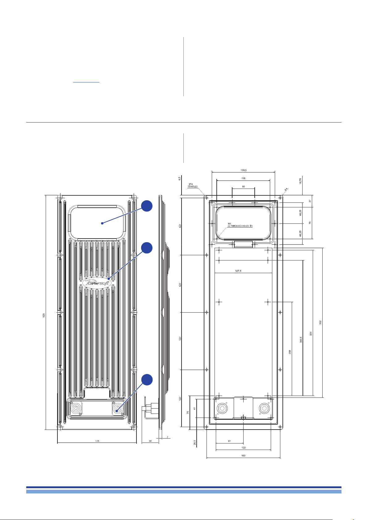
8 : 2.Suggested heatsink
Powersoft provides an IpalMod compatible aluminium alloy
heatsink, specically designed to house the amp module,
an input/output interface and the AC mains connection
1
2
(for further information, please refer to the DigiMod IK user
guide, available on Powersoft website).
3
FIGURE 2: Aluminium alloy heatsink with I/O interface bay: 1. I/O interface bay (not compat-
ible with IPAL DPC programming interface); 2. Heatsink; 3. AC mains interface.
Thermal constrains | 3
Page 14
Electromagnetic Compatibility (EMC)
9 : 1.AC MAIN filter
In order to improve the electromagnetic compatibility
an EMC lter must be inserted before the AC MAINS
plugs on the power supply. Powersoft suggests the
Schaffner FN2030-10-06 model.
FIGURE 3: Typical electrical schematic of the EMI Filter.
9 : 2.Earth connection
9
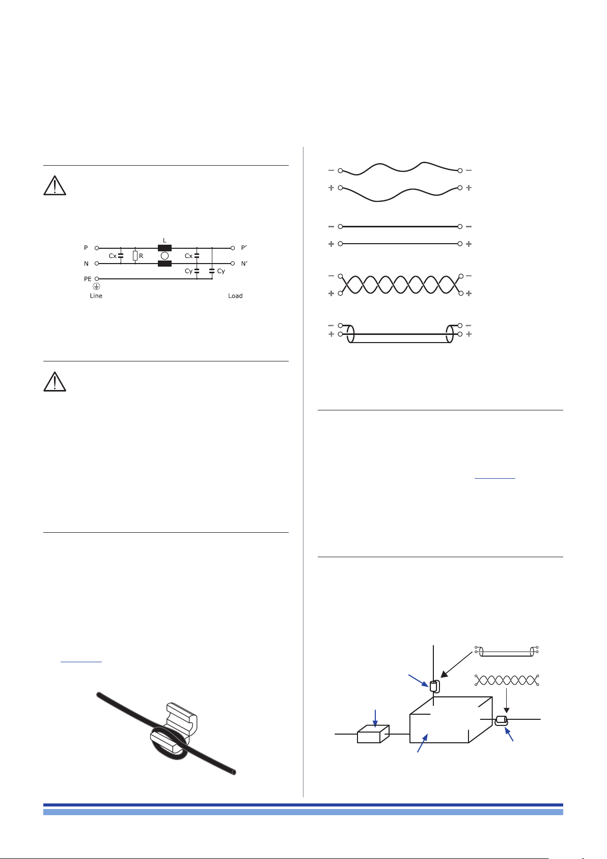
Loose pair
Configuration
prone to high
RF noise
Parallel pair
Configuration
prone to RF noise
Twisted pair
Highly immune
to RF noise
Shielded pair
Highly immune
to RF noise
This device must be powered exclusively by earth
connected mains sockets in electrical networks
compliant to the IEC 364 or similar rules. Is absolutely necessary to verify this fundamental requirement of safety and,
in case of doubt, require an accurate check by a qualied
personal.
Is absolutely necessary to ground this device using the
proper earth connection on the metal frame of the chassis; use M4 nut and bolt with proper split washer – grover
washer – to secure the earth terminal lug.
9 : 3.Cabling
Wiring between the amp module and the load may lead
to radio frequency noise. The following guide lines should
be observed:
reduced cabling length is advisable;
keep cable pairs as close as possible to each other in
order to minimize the antenna effect;
design the cabling path far from RF noise source;
set the cabling for RF noise rejection: shielded or
twisted cables are advisable conguration (ref.
FIGURE 5);
use electromagnetic compatibile connectors.
FIGURE 5: Cabling configuration.
9 : 4.Ferrite cores
Reject RF noise from input and output cabling by installing ferrite shields. Powersoft suggests the Kitagawa
RFC-H13 ferrite core.
Wrap the cable around one side of each ferrite so that
it pass through each ferrite twice (ref. FIGURE 4). Install the
ferrite shield as close as possible to where the cable plug
into the amplier. Placing the ferrite elsewhere on the cable
noticeably reduces its effectiveness.
9 : 5.Chassis shielding
If not already present on the product, a full body metal
chassis or a shielding cage will provide best shielding of RF
emission. In order to achieve the highest shielding, minimize
the amount and size of holes or opening in the chassis.
Input
signal
Ferrite core
FIGURE 4: Ferrite core installation on I/O wirings.
4 | IpalMod | User guide
AC MAINS filter
Amp module
inside
Chassis shielding
FIGURE 6: Tools and best practice for improving
the electromagnetic compatibility.
Output signal
Ferrite core
Page 15
Mechanical drawings
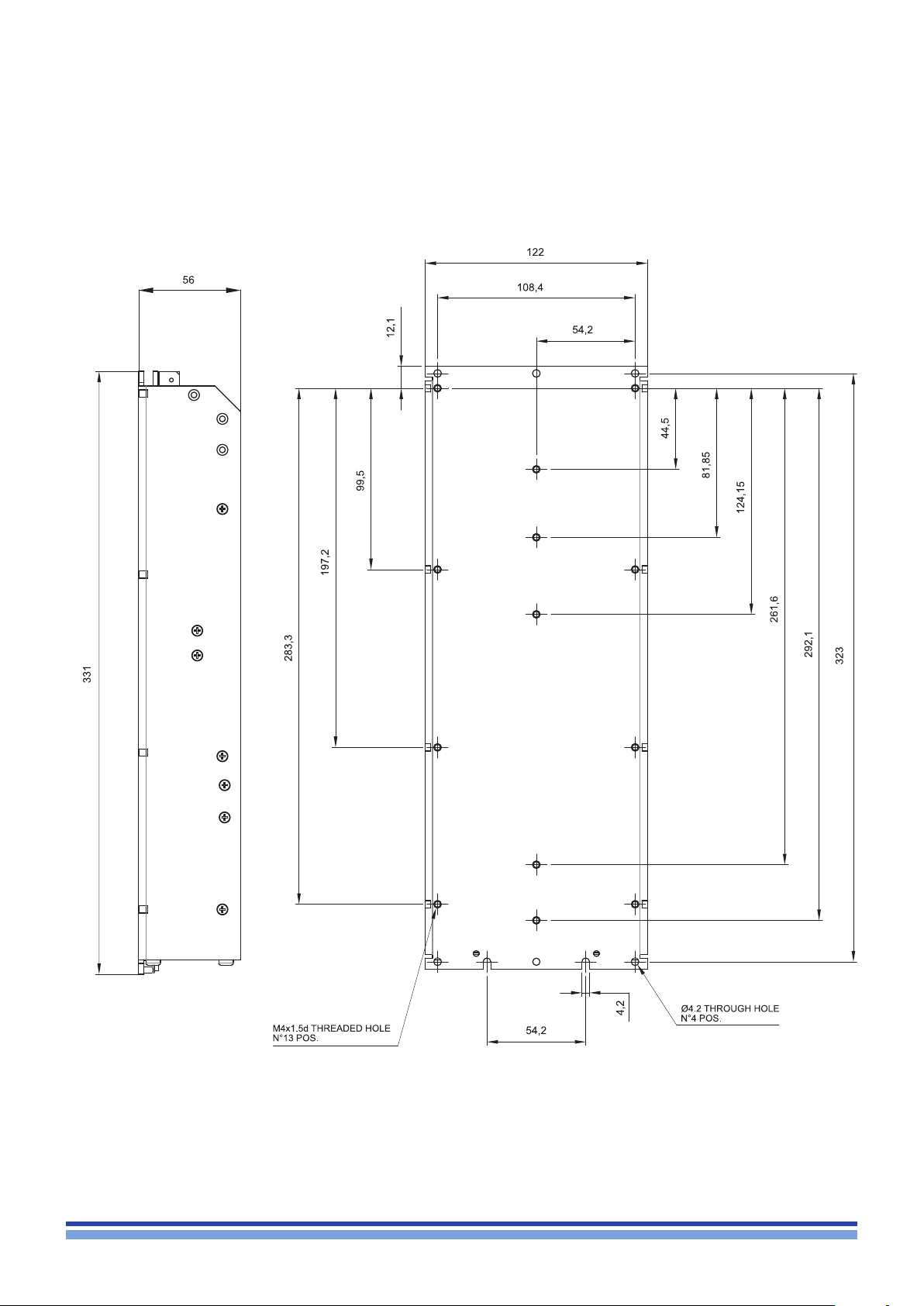
FIGURE 7: IpalMod: side and back plate (all dimensions in millimeters).
Mechanical drawings | 5
Page 16
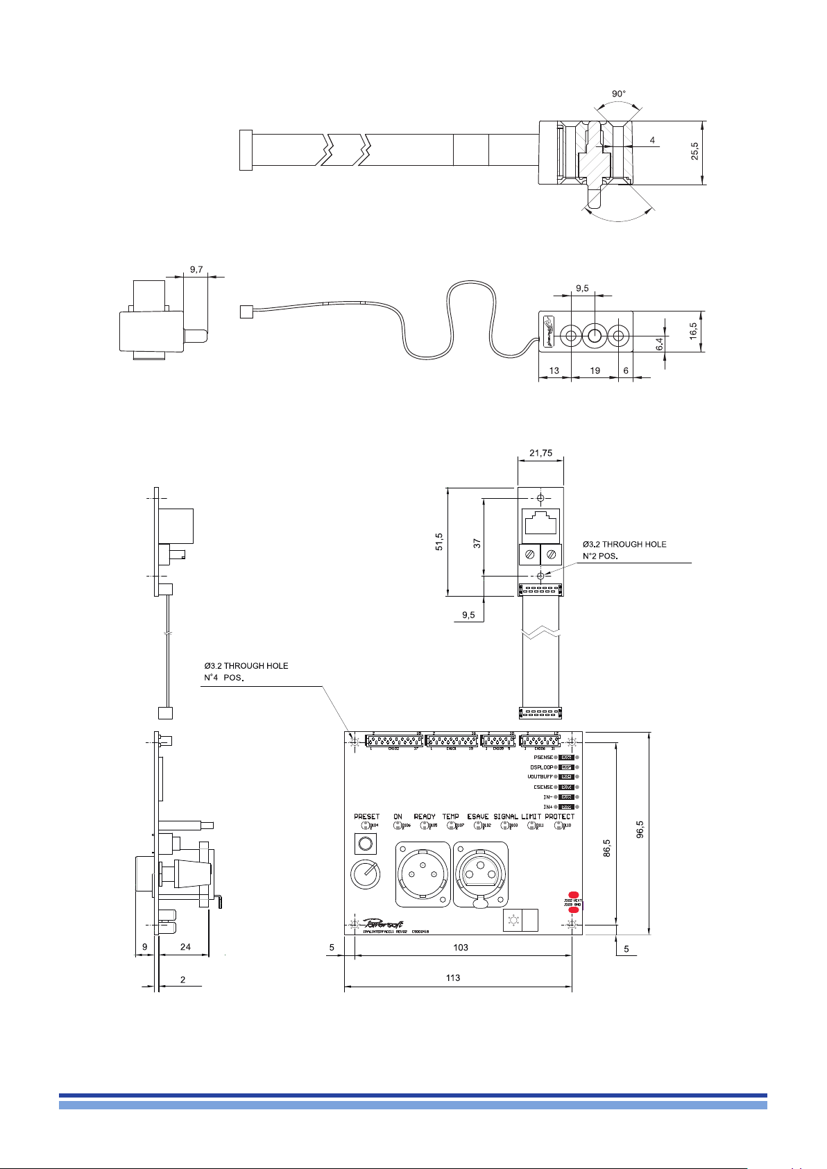
FIGURE 8: Pressure sensor (all dimensions in millimeters)
90°
6 | IpalMod | User guide
FIGURE 9: DPC interface board (all dimension in millimiters).
Page 17
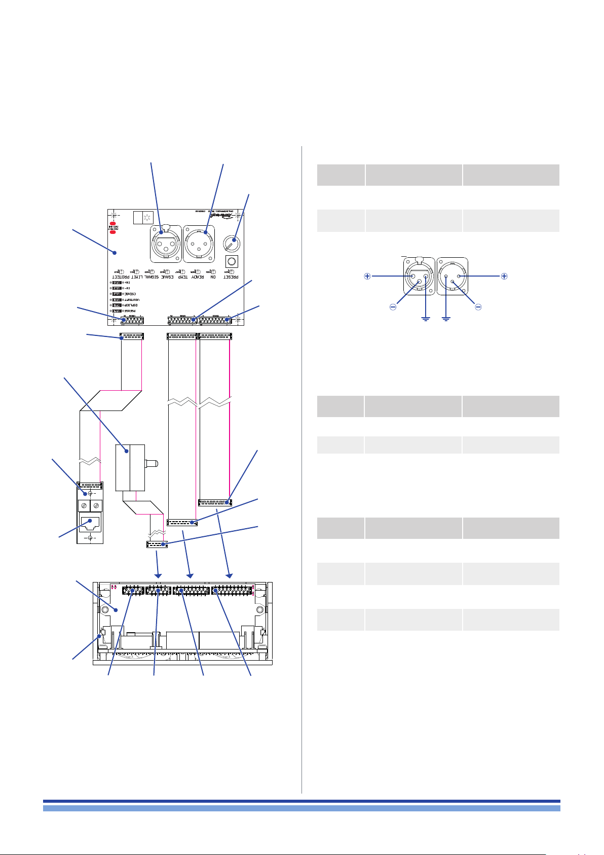
Connections
11
DPC
interface
board
CN10 6
Micro Match
12 pin
Pressure
sensor
RS-485
interface
Audio
input
Audio link
(pass through)
Input
attenuator
CN101
CN102
Micro Match
18 pin
11 : 1.Interface board: bill of connectors
CODE FUNCTION TYPE
CN107
CN108
Audio link (pass through)
balanced
Audio input
balanced
1 1 22
3 3
COLD
GND
FIGURE 11: XLR pinout.
GND
XLR-M
XLR-F
HOTHOT
COLD
11 : 2.RS-485 interface
CODE FUNCTION TYPE
CN103 RS-485 RJ45
SW101 ID selector: units rotative knob
SW101 ID selector: tens rotative knob
Micro Match
16 pin
Micro Match
10 pin
CN103
Control
board
Amp
module
CN1
FIGURE 10: DPC interface to control board connections.
CN101CN10 9
CN102
11 : 3.Control board: bill of connectors
CODE FUNCTION TYPE
CN1 Reserved
CN10 9 Pressure sensor
CN101 Interface board 1
CN102 Interface board 2
Caution: do not connect any cable to the reserved
CN1 connector on the IpalMod connection board:
doing so can result in permanent module damage.
8 pin
Micro Match Socket
10 pin
Micro Match Socket
16 pin
Micro Match Socket
18 pin
Micro Match Socket
Connections | 7
Page 18
FA2
FA1
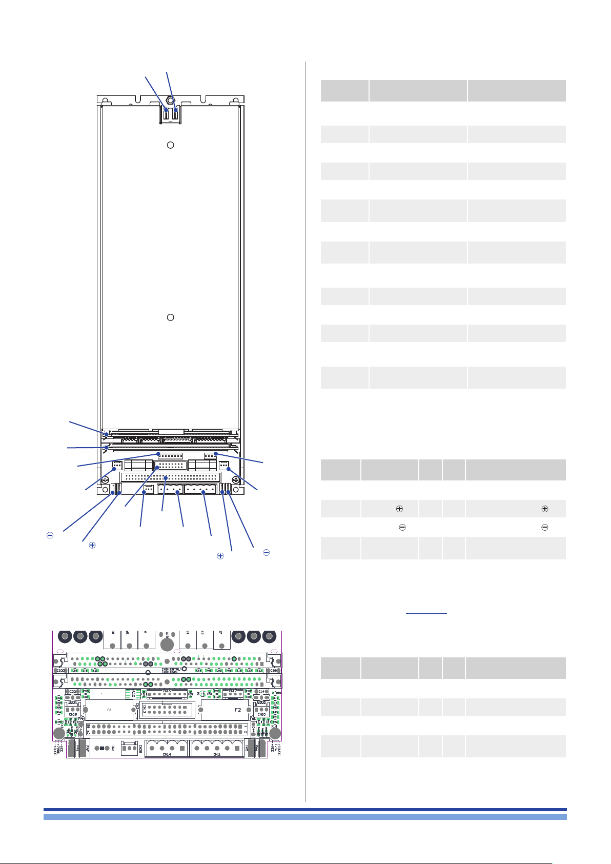
11 : 4.Amp module: bill of connectors
CODE FUNCTION TYPE
CN9
CN2
CN8 DSP/ext. circuit board 72-pin SIMM socket
CN9 Control board 72-pin SIMM socket
CN10 Built-in fan Molex 22-27-2031
CN11 Input connector MSTBVA 2,5/ 5-G-5,08
CN13
CN14 Auxiliary MSTBVA 2,5/ 4-G-5,08
CN16 System monitor
CN 17 Bypass
CN19 Built-in fan Molex 22-27-2031
CN20 Auxiliary fan Molex 22-27-2031
CN8 DSP/ext. circuit board 72-pin SIMM socket
FA1
FA2
FA5
FA7
FA6
FA8
Power bus
(reserved)
Test Connector
(reserved)
AC MAINS
Output Positive
connector
Output Negative
connector
IDC 60 Pin Male Header
IDC 20 Pin Male Header
Pin Header Strip
2.54 mm
Pin Header Strip
2.54 mm
2x
Faston 6.3x0.8mm
2x
Faston 6.3x0.8mm
2x
Faston 6.3x0.8mm
CN8
CN16
FA8
CN19
FA7
CN13
CN20
CN2
CN14
CN11
FA5
CN10
FA6
CN 17
11 : 4.1. CN11 pinout
Pin# Name IN OUT Description
1 GND
2
3
4 BY11
5 BY21
* Intended for external volume potentiometer: remove jumper in
pins 3 and 4 of CN17 to insert external linear potentiometer,
R = 1 kΩ to 2,7 kΩ (ref. FIGURE 13).
HOT
COLD
signal ground
bal/unbal input
balanced input
bypass
unbalanced line out*
bypass
unbalanced line in*
11 : 4.2. CN17 pinout
Pin# Name IN OUT Description
1 BY11
2 BY21
3 BY21
DSP/ext. circuit board
DSP/ext. circuit board
bypass
8 | IpalMod | User guide
4 BY31
bypass
Page 19

11 : 4.3. CN14 pinout
11 : 4.6. CN2 pinout
Pin# Name Description
1 GND reference ground
2 MUTE Mute command
3 Aux –12 –12 VDC OUT
4 Aux +12 +12 VDC OUT
* Intended for external volume potentiometer: remove jumper in
pins 3 and 4 of CN17 to insert external linear potentiometer,
R = 1 kΩ to 2,7 kΩ.
11 : 4.4. CN16 pinout
Pin# Name Description
1 Earect input clipping
2 Protect active protection
3 Tem p over temperature
4 Mute signal mute
5 Aux +12 +12 VDC OUT
6 GND reference ground
7 NC not connected
8 NC not connected
11 : 4.5. CN10, CN19, CN20 pinout**
Pin# Tension Description
Pin# Name Description
1-2-3- 4
5-6-7-8
9-10
+V
CC
+VCC rail bus OUT
11-12-13 NC not connected
14-15-16
17-18-19
20-21-22
23-24 +18V
25-26 –18V
27-28 +7V
29 FAN
–V
CC
DC
DC
DC
–VCC rail bus OUT
+18 V
DC
–18V
DC
+7V
DC
temperature controlled
fan command
30 NC not connected
31 MUTE Mute command
32-33
34-35
NC not connected
36
37 ESAVE Energy save in idle mode
38
39-40-41
24-43-44
45-46-47
–V
CC
–VCC rail bus OUT
48
49-50 NC not connected
51-52-53
54-55-55
56-57-58
–V
CC
–VCC rail bus OUT
59-60
1 –24 VDC OUT
2 +24 VDC OUT
3 –24 VDC OUT
** Maximum available current: 350 mA.
39
24.3
71 GND
70 GND
72 OUT 2–
69 IN 2 +
68 IN 2 –
67 BY 12
66 BY 22
2.19 4
61
65 BY 42
64 EARECT2
63 IOUT2MON
62 PROTECT2
60
59
58 MUTE
57
56
Fan
Fan
Fan
55
54
53
52 RESERVED
51 GND
50
49
48
47
45 TEMPMON
44 GND
46 OUT 4–
112.33
43 +VCCMON
42 SYNC CH
41 –VCCMON
40 GND
39 –12VDCOUT
38 +12VDCOUT
105.30
37 +5VDC
36 +5VDC
106.10
35 +12VDCOUT
34 –12VDCOUT
33 GND
32 –VCCMON
31 GND
30 +VCCMON
29 GND
28 TEMPMON
27
24
25 BY23
26 OUT 3+
22 GND
21 RESERVED
20 RESERVED
19 RESERVED
18 RESERVED
23 BY24
16
17
15 RESERVED
14 RESERVED
13 RESERVED
12 RESERVED
11 PROTECT1
10 IOUT1MON
09 EARECT1
08 BY41
07 BY21
04 IN 1+
03 GND
02 GND
01 OUT 1+
06 BY11
05 IN 1–
FIGURE 12: CN8: 72-pin SIMM board pinout (dimensions in millimiters).
Connections | 9
Page 20
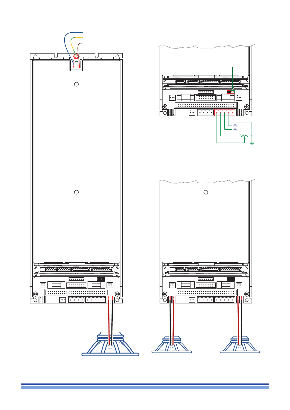
Neutral
Earth
Phase
Remove jumper to activate
external volume potentiometer
HOT
COLD
External volume
potentiometer
(optional)
GND
Single transducer mode Dual transducers mode
10 | IpalMod | User guide
FIGURE 13: IpalMod: mains and audio connections.
Page 21
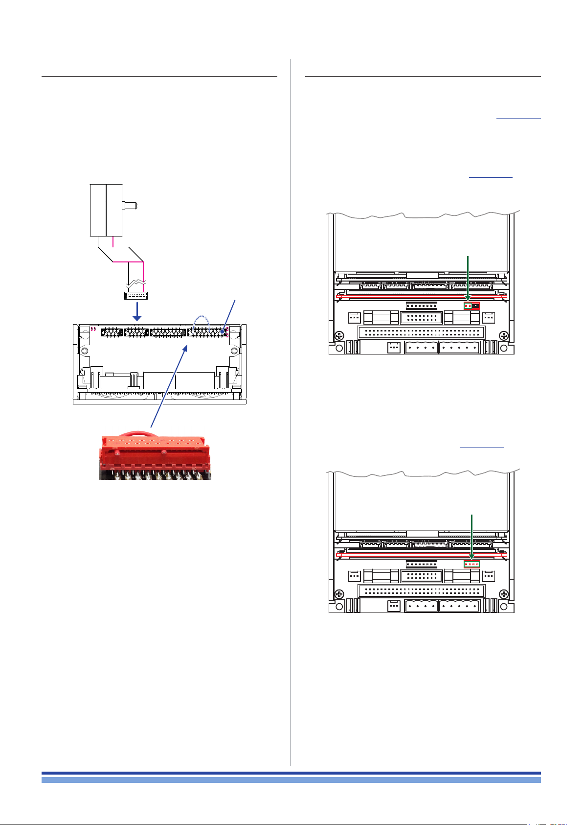
11 : 5.IpalMod without DPC interface board
11 : 6.Installing an optional DSP SIMM board
The IpalMod amplier module can operate standalone,
i.e. without the optional DPC interface board.
In order for the IpalMod to function without a connected
interface board, the CN102 Micro Match connector on the
control board must be patched:
short circuit pins number 8 and 17 on CN102.
CN102
817
The IpalMod amplier module can host an optional DSP
board such as the Powersoft DSP-D and DSP-4 interfaces,
as well as any other custom interface. Refer to FIGURE 12
for proper SIMM board dimensions and connectivity.
In order to route the signal path to the optional
DSP board on the CN8 connector remove the
jumpers from CN17 as shown in FIGURE 15.
Remove jumper to activate signal
routing to the SIMM connector CN8
FIGURE 15: Jumper settings for optional DSP board.
FIGURE 14: CN102 patch.
The patch disables the reading of the attenuator knob on
the missing interface board, in order to set no attenuation
to the signal.
Note about Powersoft DSP-D/DSP-C boards. Since the
Powersoft DSP-D and DSP-C boards implement an input
volume potentiometer on the interface panel, remove both
jumpers from the CN17 connector (ref. FIGURE 16).
Remove both jumpers to activate signal
routing to DSP-C and DSP-D boards
FIGURE 16: Jumper settings for DSP-C and DSP-D boards.
Connections | 11
Page 22
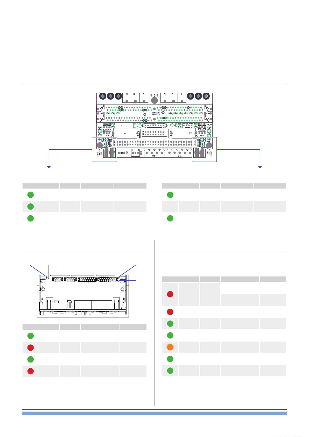
LED chart
12 : 1.Main PCB LED chart
12
Left-hand LEDs:
Color Code Signal Lighting
GREEN D26 – 18V
GREEN D1025 +7V
GREEN D1022 –V
DC
DC
CC
SOLID ON
SOLID ON
SOLID ON
12 : 3.SIMM board LED chart
D2 D8 D5
Color Code Signal Lighting
GREEN D2 +5V
RED D4 signal clip ON
GREEN D5 ready SOLID ON
DC
SOLID ON
D4
Right-hand LEDs:
Color Code Signal Lighting
GREEN D1021 +V
— — D303 NC —
GREEN D1024 +18V
CC
DC
SOLID ON
SOLID ON
12 : 2.Interface board LED chart
For a comprehensive description on system status refer
to
Color Label Signal Lighting
Signal protection
RED PROTECT
RED LIMIT Limiter active SOLID ON
GREEN SIGNAL Input signal present SOLID ON
GREEN E .SAVE
YELLOW TEMP
GREEN READY
active
No pressure sensor
connected
Energy save mode
active
Thermal protection
active
No faults, system
fully operating
SOLID ON
BLINKING
SOLID ON
SOLID ON
SOLID ON
RED D8 protection active ON
12 | IpalMod | User guide
GREEN ON System on SOLID ON
Page 23
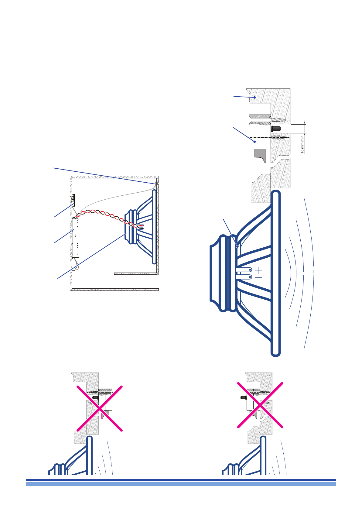
Pressure sensor
In order to guarantee high system performance, the
proper placement of the pressure sensor on the loudspeaker
cabinet and the correct connection of the transducer to the
IpalMod are paramount.
WARNING!
Inadequate or wrong positioning of the
pressure sensor can easily damage the amp
module and the loudspeaker permanently.
Pressure
sensor
interface
board
IpalMod
amp module
IPAL
loudspeaker
Cabinet
Pressure
sensor
Place the front side of
the pressure sensor
in the same radiating
eld as the front side
of the loudspeaker
Cabinet
interior
Transducer
Outside
environment
Radiating
sound eld
FIGURE 17: IPAL system.
The pressure sensor must be mounted on the front side
of the loudspeaker cabinet so that the protruding black
cylinder points in the same direction as the loudspeaker
radiating surface.
Note about loudspeaker polarity: respect signal polarity: if
needed, reverse the input signal polarity via software.
NO
Radiating
sound eld
NO
Radiating
sound eld
Pressure sensor | 13
Page 24
Power Control Manager
1
–
+
V
ext
GND
2 3 4 5 6 7 8
The DPC technology represents the most effective tool
available for the acoustic designer to achieve unprecedented
results in terms of control over the transucer displacement
and system performance in low frequencies.
Thanks to the differential pressure control, the behavior
of subwoofer and low frequency applications can be modeled in order to modify the systems response, increase
sound pressure level capabilities and enhance the overall
efciency.
A DPC system is composed by:
14
a Class-D amp module;
a differential pressure sensor;
a low-latency DSP board;
a low impedance transducer.
The DPC system performs a real time feedback between
the actual acoustic emission of the loudspeaker and the
instantaneous displacement of the transducer.
By knowing the pressure eld generated by the loudspeaker, the Zero Latency DSP controls the transducer
displacement and adaptively modify the system emission.
The system is capable to overcomes transducers non-linearities, offering a complete control over sonic performance.
14 : 1.Connect and discover the system
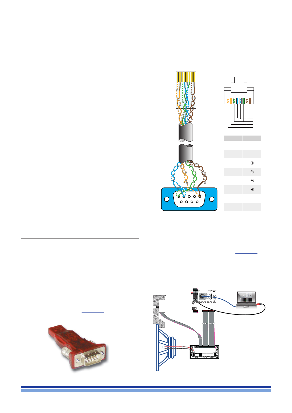
The behavior of a DPC system can be congured and
customized via a RS-485 connection by means of the
Powersoft’s Power Control Manager software. You can
download the software from the Powersoft website:
http://www.powersoft-audio.com/docman/632-power-control-manager/file
PIN Signal
1 GND
2 V
3
4
5
6
1 5
6 9
FIGURE 19: DB9-to-RJ45 adapter cable and RJ45 pinout.
Install the driver for operating the USB-to-RS485 con-
verter and install the Power Control Manager.
Properly plug the system as shown in FIGURE 20.
Once installed, the Power Control Manager shows a
blank window: the rst step is to discover all connected
devices. This can be done automatically or manually.
7 V
8 GND
ext
ext
In order to implement a RS-485 port on a personal
computer Powersoft recommend the use of the SPECTRA
USB 2.0 to RS-485 converter (browse the SPECTRA website www.spectra.ch for further information). A DB9 to RJ45
adapter is needed as well (ref. FIGURE 19).
FIGURE 18: SPECTRA #112887 USB to RS-485 converter.
14 | IpalMod | User guide
FIGURE 20: Wiring diagram.
Page 25
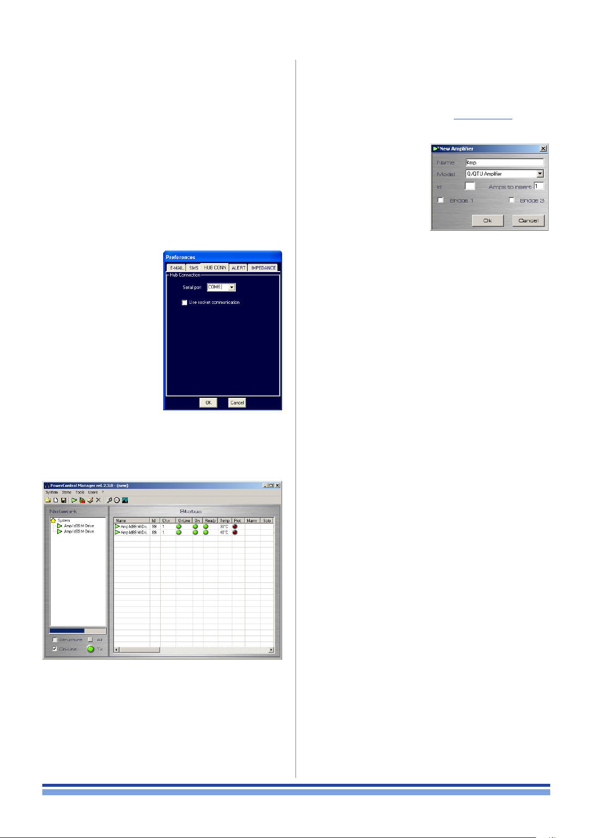
14 : 1.1. Automatic discovery
14 : 1. 2. Manual discovery
1. Connect the amp module to the computer via the
RS485 connection on the interface board.
2. Set a unique ID number on the interface board by
means of the two rotary knobs: allowed values range
from 01 to 99; 00 is reserved.
3. Turn the amplier module on.
4. Verify the name assigned to the RS485 communication
port on your PC operating system (this can be done
through Microsoft Windows® Device Manager): the
name should be something like COM5, COM6 or so
on, depending on the number of the system built-in
COM ports.
5. Start the Power Control
Manager and select
System > Preferences
on the main menu.
6. Select the “HUB
CONN” tab and make
sure that the serial port
number corresponds
to the USB-to-RS485
converter.
1. Connect the amp module to the computer via the
RS485 connection on the interface board.
2. Follow step 2 to 6 described in Chapter 14 : 1.1.
3. Select Items > Add Amplier on the main menu.
4. In the “New Amplier”
dialog window enter a
name for the amplier
and select the model.
5. Enter the ID number of
the interface board.
6. Click on “Ok”: the
added amp will appear on the amp list.
7. Close the preferences
window by clicking on
OK.
8. In the Power Control Manager window, click on the
Find Amplier button in the lower left hand corner. All
connected amp modules will be detected and automatically shown on the amp list in the Status section.
FIGURE 21: Power Control Manager:
finding connected amplifiers.
Power Control Manager | 15
Page 26
Setting the Differential Pressure Control
15
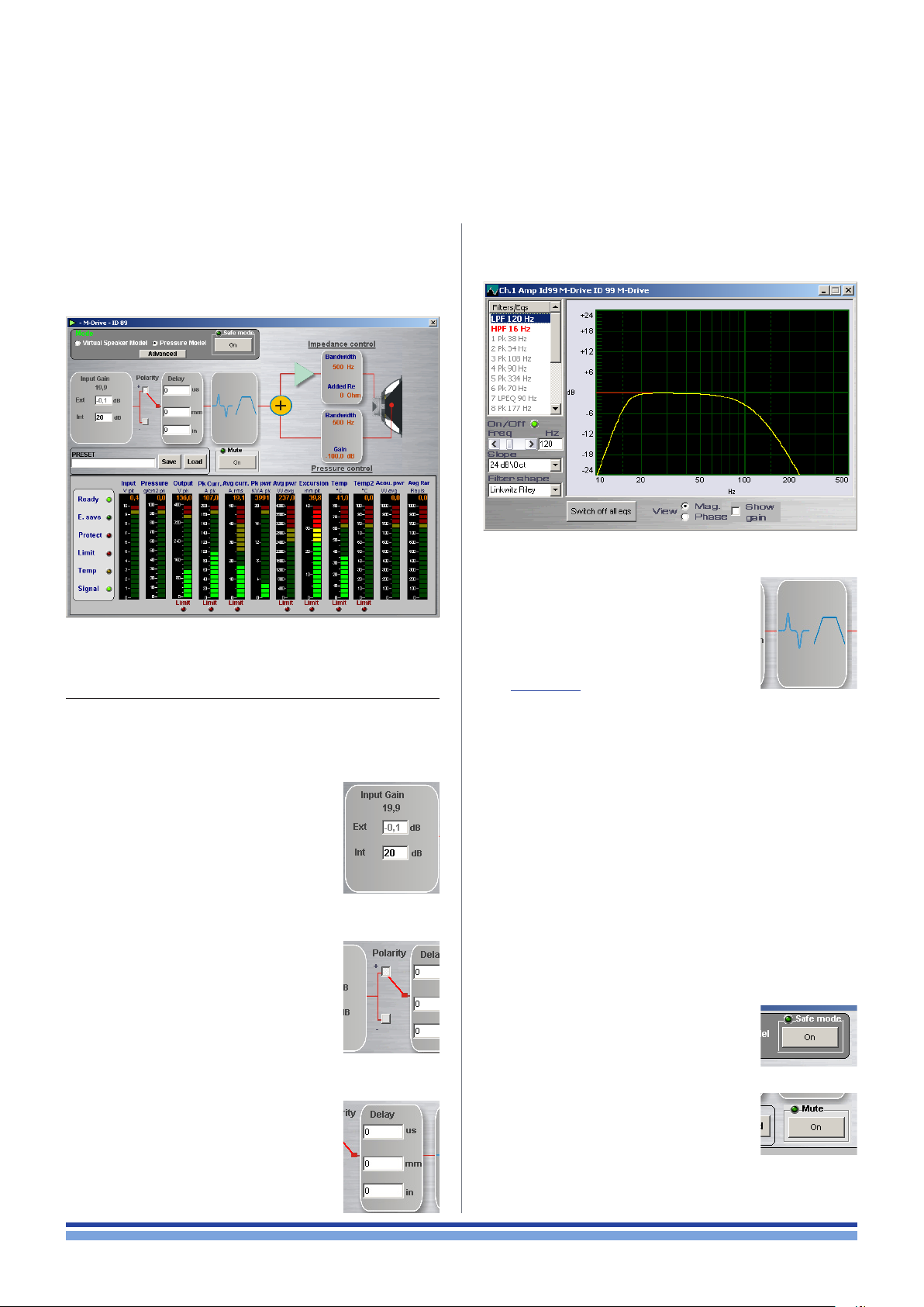
By clicking on the name of an amplier module in the
amp list, you enter the settings interface of that module. All
settings are accessible on the top section of the window;
the bottom section shows meters and status leds.
FIGURE 22: Power Control Manager: module settings.
15 : 1.Global settings
Global settings affect the behavior of the system regardless of the operating mode (Virtual Speaker model /
Pressure Model).
15 : 1.1. Input Gain
Set the maximum volume of the input
signal. The attenuator knob on the interface board modies the signal volume in
series with the internal settings.
The number just below the label
“Input gain” shows the sum Int + Ext
in decibels.
Ext shows the attenuation (negative
dBs) achieved by means of the attenuation knob.
Int allows to dene the internal signal
volume in dB.
15 : 1. 2. Polarity
The input signal can be phase reversed
by clicking on the polarity boxes.
15 : 1.3. Delay
The input signal can be delayed by user
denable amounts via the delay processing block. Parameters can be accessed
and set from the main window.
Delay values can be entered in the time domain (us) or as
physical linear distances (in mm or in inches).
FIGURE 23: Parametric equalizer.
15 : 1.4. Parametric equalizer
A fully parametric equalizer processing
block is available to ne tune the system’s
sound. By double clicking on the equalizer
processing block, a new window opens
(ref. FIGURE 23).
A list of parameter presets of commonly used equalization schemes is available on the left hand menu. Double
clicking on the lter name selects it and adds it to the processing chain. Each individual selected lter can however
be turned on or off by clicking on the “on/off ” green LED
button at the bottom of the lter list.
The slider controls beneath the preset lters list allow
real time variations of lter parameters such as the lter’s
central frequency, gain, Q and type. A log scale diagram of
each lter’s effect is presented on the right hand side of the
eq window.
The red line represents the selected lter frequency
shaping.
The yellow line represents the cumulative effect of all the
lters on the entire input signal.
15 : 1.4.1. Safe Mode and Mute
Some settings may brings to system
instability and critical operating condition. The Safe Mode button provides a
protection against critical settings: when
activated, this function will not allow the
output power to exceed a set limit.
The Mute button is provided as well to
mute audio playback.
16 | IpalMod | User guide
Page 27
15 : 2.Operating modes
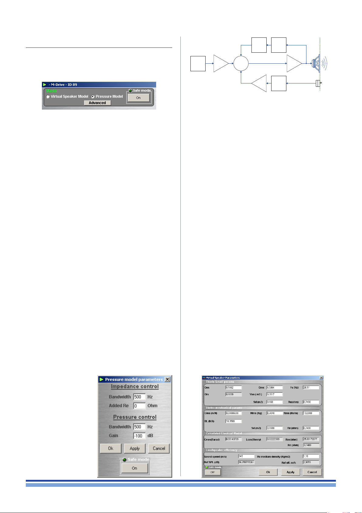
The DPC technology can be exploited in two operating
modes which differ in signal processing path and application scenarios.
LPFRe
Input
signal
Input
gain
DSP
Feedback
gain
LPF
FIGURE 24: Pressure model feedback loop.
Current feedback loop
Transducer
Output
stage
Pressure feedback loop
Pressure
sensor
Radiating
sound field
15 : 2.1. Pressure Model Mode
The amplier’s output signal is modied in real time as
a result of the combination of the input audio signal and the
feedback loop.
The alteration is applied to the input stage so to minimize
the difference between the desired output and that measured and reported by interpolating two the feedback loops.
15 : 2.1.1. Pressure control (pressure feedback loop)
This loop brings the pressure level measured at the readiating sound eld, back to the input stage. This is achieved
by feeding the pressure sensor measurement through a rst
order low pass lter (LPF) and a linear amplier.
The parameters that can be set by the user for this feedback loop therefore are:
the loop gain, expressed in dB and limited by the sys-
tem’s stability, dening the strength of the feedback
effect;
the LPF bandwidth, dening the range of frequency at
which this feedback loop is active.
It is important to set the loop gain carefully, as too high
a value will bring the system to instability. This results in a
loud “ship’s horn” sound which can potentially damage the
system if not silenced after a short time. This can be done
by lowering the feedback loop gain until the sound stops.
The entire pressure feedback loop can be bypassed by
entering a loop gain value of -100 dB and an Re value of 0
(see below for Re): with these value the loop’s effect will be
disabled.
15 : 2.1.2. Impedance cotrol (current feedback loop)
This loop brings back a voltage signal proportional to
the current present at the output stage to the system’s
input. The signal taken from
the output is rst ltered by
a rst order low pass lter.
Following this step, the
current/voltage translation
is carried out by a virtual
resistor named “Re”.
The importance of this
series resistor relies in the
difference between traditional transducers and IPAL
compatible speakers. IPAL
speakers have an extremely
low impedance. This means
that they manifest a violent, extremely high Q resonant
peak which can result in an unnatural sound reproduction.
By adding a virtual series resistor Re, the entire system’s
resonant peak will be slightly attened and widened in a
way that mimic’s a traditional speaker’s lower Q resonance.
This resistor will however not affect the power transfer
from input to output as this is not a “real” physical resistor
subject to ohmic heating.
The parameters the user can set for this feedback loop
therefore are:
the “added Re” value, dening the additional series
resistor inserted to simulate a traditional speaker behavior. This is usually a small number, which aims to
return the apparent loudspeaker resistance to a traditional 2-4 Ohm value;
the LPF bandwidth, dening the range of frequency at
which this feedback loop is active.
15 : 2.2. Virtual Speaker Mode
The virtual speaker mode allows the user to enter a set
of Thiele Small parameters that describe a transducer: this
can be either a physically existing loudspeaker the user
would like to emulate, or a non-existing, ideal transducer.
The DSP uses these parameters to drive the amp module
so that the entire system performs exactly as if the cabinet
houses the wanted transducer.
The system automatically adapts its internal processing using information from the pressure sensor to virtually
reproduce the behavior of the user dened transducer. The
way this is achieved is practically user-transparent, meaning
that the user can “interact” with the system only by changing the virtual speaker’s parameters and not the system’s
internal loop parameters.
Setting the Differential Pressure Control | 17
Page 28
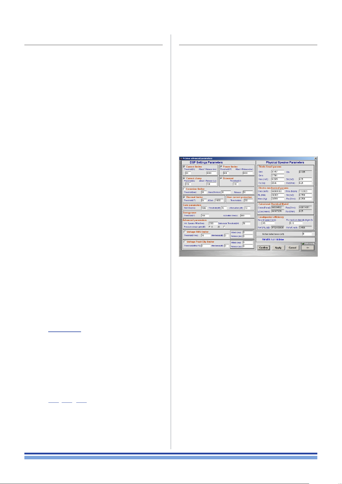
15 : 3.Thiele/Small parameters
15 : 4.Advanced parameters
The Thiele/Small parameters are electromechanical
parameters that dene the performance of a loudspeaker
driver. T/S parameters are provided by driver manufacturers.
In order to setup the system, you are asked to enter the
following T/S parameters:
Fs: loudspeaker resonant frequency in free air (Hz);
Qes: electrical loudspeaker damping at resonance
(unitless);
Qms: mechanical loudspeaker damping at resonance
(unitless);
Vas: volume of air with the same acoustic compliance of
the driver suspension in free air (cubic meters or liters);
Re: electrical resistance of voice coil (Ω);
Sd: effective projected surface area of the driver dia-
phragm (square meters).
Cms: suspension compliance (m/N)
Mms: effective moving mass combining cone, coil, all
moving parts and the acoustic load by the air in contact with the loudspeaker cone (kg);
Rms: suspension and all moving parts losses or
damping (mechanical ohm);
Advanced parameters are common to both Virtual
speaker and Pressure model modes. Before accessing the
Advanced parameters window by clicking on the Advanced
button, a dialog box asking a password appears.
The Advanced parameters default password is
lippo
This extra step in necessary to ensure that system
parameters are not changed by mistake as incorrectly set
values can permanently damage the system.
As an added precaution, when the user tries to assign a
parameter value outside the range of acceptable values, the
text box is highlighted in red and the parameter automatically set below the safety threshold.
Bl: force factor, i.e. strength of the magnetic eld times
the length of the wire forming the voice coil (T·m or N/A).
Furthermore, the system takes into account the folloging data:
Sound speed: speed of sound (meter/second)
Ro medium density: air’s medium density (kg/m3)
15 : 3.1. Calculated parameters
The Power Control Manager derives the following data:
Qts: total loudspeaker damping at resonance combin-
ing electric and mechanical effect (unitless):
Qts =
Cmes: electrical capacitive equivalent of the moving
mass Mm (farad)*;
Lces: electrical inductive equivalent of the suspension
compliance Cm (henry);
Ref eff. no: loudspeaker free air standard reference
efciency (unitless);
no =
Ref eff. no%: same as Ref eff. no in percentage;
Qms·Qes
Qms+Qes
Ro Sd(Bl)
2�c MmsRe
2
( )
2
FIGURE 25: Advanced parameters.
15 : 4.1. DSP setting parameters
The Zero Latency DSP implements a number of limiters
that can be activated and customized by the user:
Current limiter
Set a threshold limit and the attack/release time for the
average (rms) output current.
Current clamp
The Current Clamp is a faster acting current limiter.
Current Clamp is meant to limit spikes of current, effectively
protecting the output stage and the connected loudspeaker
from dangerous high peak current: this is different respect
the short circuit protection that works by sensing decreasing rails values.
The current threshold value does not indicate the
maximum output current, but the current level at which the
limiter will start sensing spikes of current. Output current
level can exceeds the clamp threshold considerably due to
the internal limiter design.
Ref SPL: reference sound pressure level (dB):
Ref SPL = 112 + 10 log(no).
18 | IpalMod | User guide
Brownout
Brownout is an even faster acting output peak power
limiter, and works on a different principle than all other
limiters.
Page 29

This protection system quickly reduces the amplier
gain when the rails voltage decrease quickly due to an excessive power draw from the load. Threshold voltage value
is the value beneath which the rail voltage must drop for the
limiter to begin acting. A threshold voltage value of 0 V, for
example, disables the limiter.
The hold time indicates how long the gain reduction occurs after the output signal falls below the threshold. The
attenuation parameter indicates the amount by which the
output gain is decreased with respect to no attenuation.
Note that the system gain changes slowly and not abruptly
so the effect is unnoticeable.
Power Limiter
Ensures that the real part of the average output power
does not exceeds the limits set by the user.
Overcurrent protection
The overcurrent protection acts similar to the current
clamp but faster. You can just set the threshold.
Excursion Limiter
The excursion limiter keeps the loudspeaker cone displacement within a user dened range. The threshold cone
excursion is set in mm. The excursion limiter works through
a current loop, dynamically changing the value of a resistance proportionally to the displacement of the cone with
respect to its resting position.
It is important to note that this position is estimated;
its accuracy depends on the precision of the connected
speaker physical parameters entered in the Physical
Speaker Parameters section in the advanced parameters
window (see below).
The Gain (ohm/cm) parameter sets the displacement/resistance conversion factor, so as to regulate the intensity of
the limiting effect. For a given cone displacement, a higher
gain value yields a more severe limiting action. The release
time determines the time needed for the limiter to release
the cone.
Please note that the maximum cone excursion set in this
window only determines the cone displacement value that
activates the effect of the limiter; it does not represent the
maximum excursion the cone will display. The limiter’s internal design allows for a certain margin between maximum
displacement threshold value and effective cone displacement, the latter being potentially higher.
Thermal Limiter
The thermal limiter reduces the rail voltage by an amount
proportional to the difference between the threshold temperature and the measured output stage temperature in
order to lower the module’s temperature.
Lowering the rails voltage reduces output power which
in turn decreases ohmic heating of the output stage. The
scaling factor that governs the rails reduction as a function of this temperature difference is called KGain; it can
be entered by the user, although the default value (1000)
is already an empirical optimum. For a given temperature
difference, a higher KGain factor yields a more severe rails
voltage reduction.
Gate
The system is equipped with a gate output block intended to improve the overall signal-to-noise ratio. The
gate reduces the output gain for small signals interpreted
as noise.
Energy Save
In order to reduce power consumption when the amp is
not receiving any viable input signal, the IPAL system enters
an energy save operation mode. Lower energy consumption
is obtained lowering the rails voltage to the value entered in
the voltage threshold. The energy save mode is activated
only after no signal input is detected for more than the use
set activation time.
Advanced Parameters: Virtual Speaker RP (mohm)
The Virtual Speaker RP is a scaling factor used by the
pressure sensor. This depends on the specic pressure
sensor in use and must therefore be changed only if the
sensor is changed.
Advanced Parameters: Safe Mode Threshold
The Safe Mode provides a protection against critical
settings that may bring the system to instability or even to
damages.
When Safe Mode is active, the output power is limited by
the value enetered as Safe Mode Threshold.
Special care should be used while setting this value:
it must not be greater than the maximum power handling
capabilities of any part of the system.
Voltage RMS Limiter
Set a threshold limit and the attack/release time for the
average (rms) output voltage.
Voltage peak/Clip Limiter
Set a threshold limit and the attack/release time for the
peak output voltage.
Physical Speaker Parameters
Parameters in this section refer to the transducer
and are the same described in Chapter 15 : 3.Thi ele/S mall
parameters. Please note, however, that the parameters en-
tered in this window refer to the real loudspeaker whereas
those entered in the Virtual speaker mode may refer a virtual
transducer.
15 : 5.More about DPC
For more information about the IPAL and DPC technologies, please refer to: Blasizzo, Desii, Di Cola, Lastrucci,
Practical applications of a Closed Feedback Loop
Transducer system Equipped with Differential Pressure
Control, presented at the 131st AES Convention New York,
New York, October 20-23, 2011.
Setting the Differential Pressure Control | 19
Page 30
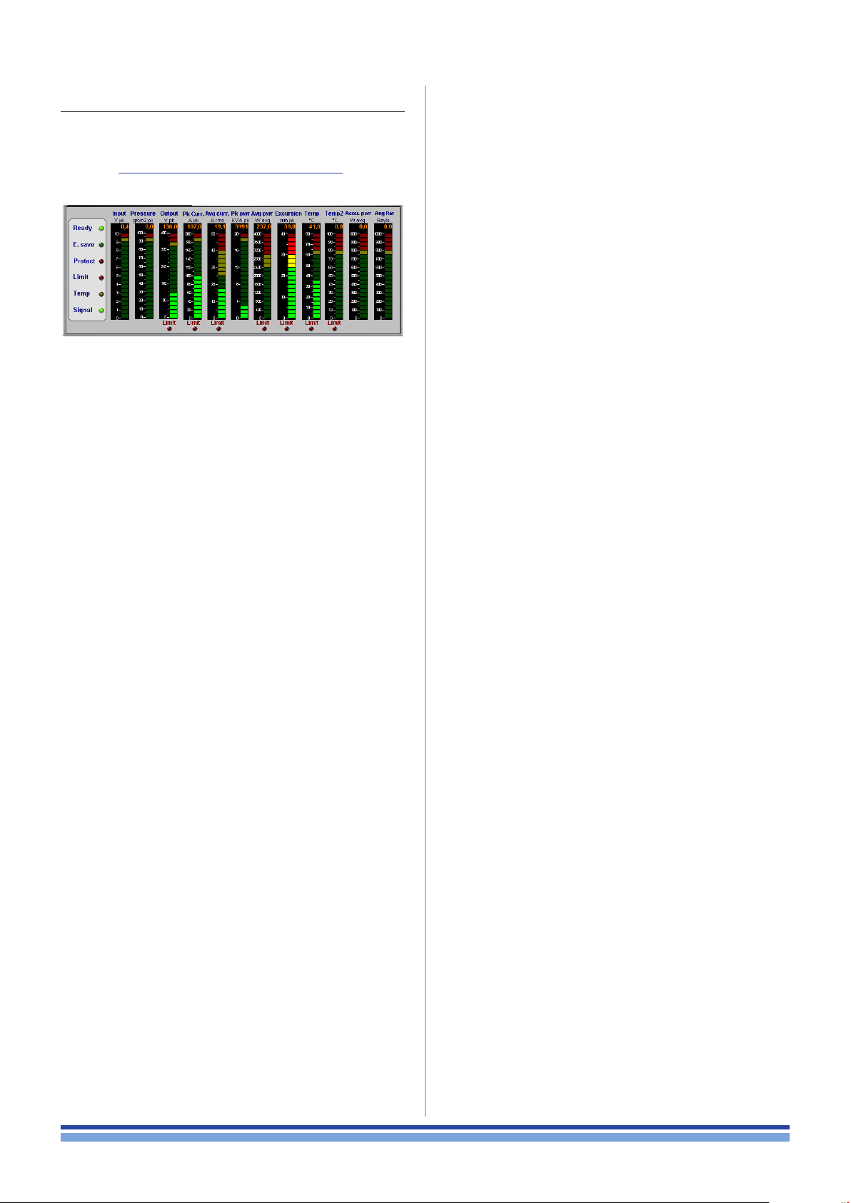
15 : 6.Metering
The bottom section of the Power Control Manager interface contains a copy of the LED located on the interface
panel (ref. Chapter 12 : 2.Interface board LED chart) and some
meters that provide a feedback on system performance.
15 : 6.2. Meter strips
Input (Vpk) – Input peak voltage measured before input gain/
attenuation processing: the meter therefore represents the
signal level entering the system before any processing is
performed.
Pressure (g/cm
the pressure sensor.
Output (Vpk) – Output voltage peak level. The Limit red LED
underneath the meter strip lights when the measured output
voltage is being clipped to the system’s maximum possible
voltage level.
2
) – Peak pressure level as measured by
pk
FIGURE 26: Power Control Manager: metering.
15 : 6.1. LEDs
Ready – When this LED is on the amp is ready and in proper
functioning conditions. When this LED is off the amp is non
functional due to a power fault. This can be either:
internal: if there is an internal power failure;
external: if the amp’s load current draw has exceeded
the maximum acceptable values set by the current
protection limiters.
E.Save – When this LED is on the amp has entered the energy save mode, after having detected no input signal for a
selected timespan. The amp’s power consumption is minimized by decreasing rails voltage.
Protect – This LED lights when short circuit protection has
acted to prevent amplier damage. This was caused by the
output current trying to increase above the value set by
the user in the overcurrent protection section. No output is
possible when this LED is on. The amplier checks every 2
seconds if the short circuit condition is still in place. If not,
the limiting action is interrupted, the LED is turned off and
output is possible again.
Limit – This LED is on every time any limiting action is undertaken by any system limiter.
Temp – When this LED is on, the temperature of the module’s nal stage has gone over the user set limit.
Pk Curr. (Apk) – Peak output current. The Limit red LED underneath the meter strip lights when the measured output
peak current rises above the limit set in the current clamp
threshold.
Avg curr. (A
) – Root mean square current value. The Limit
rms
red LED underneath the meter strip lights when the measured output average current exceeds the limit set in the current limiter threshold.
Pk pwr (kVApk) – Peak output power.
Avg pwr (W
) – Average output power. The Limit red LED
avg
underneath the meter strip lights when the measured average power rises above the limit set in the power limiter
threshold section.
Excursion (mmpk) – Peak estimated cone excursion with
respect to the central resting position. The Limit red LED
underneath the meter strip lights when the estimated cone
excursion goes beyond the limit set in the excursion limiter
threshold section.
Temp (°C) – Output stage temperature. The Limit red LED
underneath the meter strip lights when the measured
temperature rises above the limit set in the thermal limiter
threshold section.
Temp2 (°C) – Transducer temperature (external probe needed).
Acou. pwr (W
) – Estimated average acoustic power.
avg
Signal – This LED is on when a signal is detected at the input.
20 | IpalMod | User guide
Avg Rar (Rayls) – Estimated average acoustic impedance.
Page 31

Hardware protections
16
The architecture of Powersoft’s ampliers encompass
several protection mechanisms triggered by harmful signal
and temperature. Protection systems and triggers are independently implemented in the power supply section (power
supply protection) and the amplier section (amplier protections); most of the protection threshold values can be
set through the Power Control Manager (ref. Chapter 15 : 4.
Advanced parameters).
15 : 7.Power supply protections
Power supply protections aim to isolate a faulty section
in electrical power system from the rest of the device in
order to prevent the propagation of the fault and limit device
damages.
15 : 7.1. Primary AC mains overcurrent protection
AC main overcurrent are ltered by two 10 A time-lag
fuses (also known as time-delay or low blow-fuse). The
purpose of the time lag fuses is to allow the supply in electricity for a short time before the fuses actually blow. If the
time-lag fuses blow out, the amplier switch off; replace the
fuses with proper 10 A time-lag fuses in order to restore the
full functionality of the amplier.
15 : 8.1. Auxiliary power protections
Auxiliary plugs are protected against short circuit: a
poliswitch opens the auxiliary circuits when the current
drawn exceeds 1 A.
15 : 7.2. Primary AC mains overvoltage protection
AC mains overvoltage threshold is set to 295 V
AC mains voltage exceeds 295 V
working; the device does not turn completely off but falls in
a “sleeping” mode: the power supply turns on again when
the AC mains voltage drops under 290 V
AC mains overvoltage are well tolerated by the power
supply: no damages can be caused to the system even in
case of severe overvoltage up to 400 V
the power supply stop
rms
.
rms
.
peak
. If the
rms
15 : 7.3. Primary thermal protection
The temperature is detected at power supply and triggers the heat dissipated by the device: if the temperature
rises exceeding components tolerances, the primary
hardware thermal protection starts lowering the rails voltage in order to lower the heat wasted and keep the overall
efciency high.
The process is drived by the DSP section of the Control
Board and is auto-adaptive, aiming to maintain the system
up even in heavy thermal condition.
15 : 8.Amplifier protections
The amplier section protections are managed by the
DSP section on the Control Board and can be customized
by means of the Power Control Manager software.
Hardware protections | 21
Page 32

Support and warranty
17
17 : 1.Service
There are no user-serviceable parts in your amplier.
Refer servicing to qualied technical personnel. In addition to having an in-house service department, Powersoft
supports a network of authorized service centers. If your
amplier needs repair contact your Powersoft dealer (or
distributor). You can also contact the Powersoft Technical
Service department to obtain the location of the nearest
authorized service center.
17 : 2.Warranty
POWERSOFT guarantees its manufactured products to
be free from defective components and factory workmanship for a period of 12 (twelve) months, starting from the
date printed in the invoice of purchase.
All warranty repairs and retrots must be performed at
Powersoft facilities or at an Authorized Service Center at
no cost for the purchaser. Warranty exclusion: Powersoft’s
warranty does not cover product malfunctioning or failure
caused by: misuse, abuse, repair work or alterations performed by non-authorized personnel, incorrect connections, exposure to harsh weather conditions, mechanical
damages (including shipping accidents), and normal wear
and tear.
Powersoft will perform warranty services provided that
the product is not damaged during transportation.
17 : 2.1. Return of Goods
Goods can be returned to Powersoft only after they
have been granted a Return Merchandise Authorization –
RMA – number to be attached to the external packaging.
Powersoft (or its Authorized Service Center) has the right to
refuse any returned good without a RMA number.
17 : 2.2. Repair or replacement
Powersoft reserves the right to repair or replace any
defective goods covered by product warranty at its sole
discretion and as it deems best.
17 : 2.3. Cost and responsibility of transport
The purchaser (or end user/customer) is solely responsible for all transportation costs and risks associated
with sending warranty covered goods to Powersoft or its
Authorized Service Center. Powersoft will assume full responsibility and cover all costs incurred to send the goods
back to the purchaser (or end user/customer).
17 : 3.Assistance
Even though most product malfunctioning can be solved
at your premises through Powersoft Customer Care or
your direct knowledge, occasionally, due the nature of the
failure, it might be necessary to return defective products
to Powersoft for repair. In the latter case, before shipping,
you are kindly asked to follow step by step the procedure
described below:
Obtain the “Defect Report Form” by contacting our
Customer Care Department via email: service@
powersoft.it or download the“Defect Report Form”.
Fill out one “Defect Report form” for each returned
item (the form is an editable tab guided document)
and save as your name, amp model and serial number
(for example: distributorname-MDRIVE-17345.
doc) providing all required information except the
RMA code/s and send it to [email protected] for
Powersoft approval.
In case of defect reports approved by the Powersoft
Customer Service Representative you will receive
an RMA authorization code (one RMA code for each
returning device). Upon receiving the RMA code
you must package the unit and attach the RMA
code outside the pack, protected in a waterproof
transparent envelope so it is clearly visible.
All returning items must be shipped to the following
address:
Powersoft S.p.A.
Via Cadolingi, 13
50018 Scandicci (FI) Italy
In case of shipment from countries NOT belonging
to the European Community make sure you have
also followed the instructions described in the
document available for download at the TEMPORARY
EXPORTATION / IMPORTATION PROCEDURE link at
http://www.powersoft-audio.com/en/support/service.
Thank you for your understanding and cooperation and
continued support as we work to improve our partnership.
22 | IpalMod | User guide
Page 33

Specifications
AC Mains Supply
Power supply
Nominal power requirement AC 100 V - 240 V, 50/60Hz
Operating range 80 - 278 Vrms
Power consumption
IDLE (energy save) 21 W
Average 400 VA
Efciency @ 1/4 max power 81%
Inrush current 34.5 Apeak (7 Apeak after 5 s)
Audio
Number of output channels 1
Gain 32 dB
Dynamic Range (A-Weighted @ 8 Ω) 65 dB
Output Noise (A-Weighted @ 8 Ω) -44 dB
Frequency Response (-3 dB, 1 W @ 4 Ω) 10 Hz - 620 Hz
THD+N (from 0.1 W to Full Power)
DIM (from 0.1 W to Full Power)
Universal regulated, switch
mode, with PFC
< 0.6%
(typical < 0.4%)
< 1.6%
(typical < 0.8%)
Output Stage
Maximum output power 8500W @ 1Ω
Maximum unclipped output voltage 180 V
Maximum output current 110 A
Virtual Speaker® mode
Thiele-Small parameters Qes - Qms - Vas - Sd - Fs - Re
Electromechanical model parameters Qes - Qms - Vas - Sd - Fs - Re
Differential Pressure Control® mode
Impedance control parameters Bandwidth, added Re
Pressure control parameters Bandwidth, slope, gain
DSP
Equalizer
Crossover
Limiters
Metering
Raised-cosine, custom FIR, parametric IIR:
peaking, hi/lo-shelving, all-pass,
band-pass, band-stop, hi/lo-pass
linear phase (FIR), hybrid (FIR-IIR), Butterworth,
Linkwitz-Riley, Bessel: 6 dB/oct to 48 dB/oct (IIR)
TruePower™, RMS voltage, RMS current, Peak limiter,
Excursion limiter, Current clamp,
Brownout limiter, thermal
Input & output voltage, pressure, peak & average current,
peak & average power, excursion, temperature
peak
peak
Page intentionally left blank
Specifications | 23
Page 34

24 | IpalMod | User guide
Page intentionally left blank
Page 35

Page 36

Powersoft S.p.A.
Via Enrico Conti, 5
50018 Scandicci (FI) Italy
Tel: +39 055 735 0230
Fax: +39 055 735 6235
General inquiries: [email protected]
Sales: [email protected]
Application & technical support: [email protected]
Service & maintenance: [email protected]
Compliance questions: [email protected]
powersoft-audio.com
 Loading...