

Page 1

®
Via Enrico Conti, 5
50018 Scandicci (FI)
www.powersoft-audio.com
Technical Support
Should you encounter any difculties in operating this amplier
module, please do not hesitate to contact our technical support.
We will be glad to be of assistance.
Powersoft
Via Enrico Conti, 13/15
50018 Scandicci - Firenze
Italy
Tel/fax: +39 055 735 1386
DigiMod 1000
DigiMod 1000 is a class-D amplier module delivering up to
1000W, and capable of driving an additional 2-channel output stage
(DigiMod 1000NPS) to cover a wide range of applications, from
small/medium subwoofers to 2-way monitors, as well as 3-way
systems.
Specically designed DSP boards with advanced processing, remote
control and networking capabilities are available for DigiMod 1000,
to perfectly t with the amplier and providing a complete solution
in a compact package.
Quick Guide DigiMod 1000
Specications
AC Mains Powe r
Oper ating voltage
AC 195V – 250V @ 50/60Hz,
I
*
nom
= 1.6 A
RMS
AC 95V – 125V @ 50/60Hz,
I
*
nom
= 3.2 A
RMS
*
1/8 max outp ut power
Efciency > 85% (typi cal )
Power cons umption
I/8 of max p ower @ 8 � bridged 178 VA
Max aux s upply curre nt draw 200 mA
Construction
Dimensions
216 mm x 122 mm x 53 mm
(8.5” x 4. 8” x 2”)
Weight 1.05 kg (2 .3 lb)
Page 2
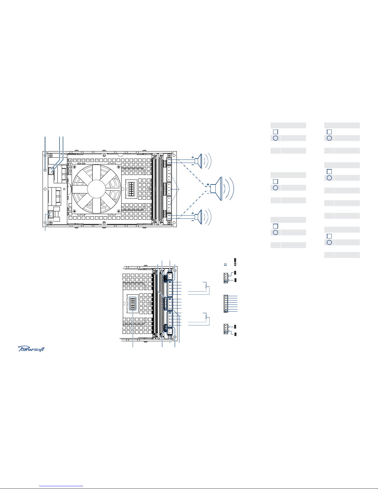
OUT 1
OUT 2
AC MAINSGROUND
Place jumper to set
operating voltage to
115 V
AC
Phoenix
pitch: 5.08
SIGN. GROUND 1
BAL. INPUT 1 +
BAL. INPUT 1 –
BY11
BY21
SIGN. GROUND 2
AUX SUPPLY GND
MUTE
+12 VDC OUT
–12 VDC OUT
BAL. INPUT 2 +
BAL. INPUT 2 –
BY12
BY22
EARECT1
PROTECT1
TEMP
MUTE
+12VDC OUT
GND
PROTECT2
EARECT2
Remove jumper
to enable DSP
Remove jumper to
insert external circuit
Remove jumper to
insert external circuit
Remove jumper
to enable DSP
jumper not in place
jumper in place
DEFAULT SETTINGS
CN16
CN16
CN17
CN17 CN3
CN11
CN18
CN18
CN7
CN15 CN12
CN14
pin 1
Via Enrico Conti, 5
50018 Scandicci (FI)
www.powersoft-audio.com
CN16
1 EARECT2
2 PROTE CT2
3 GND
4 +12VDC OUT
5 MUTE
6 TEMP
7 PR OTECT1
8 EARECT1
CN12
1 SI GN. GND 2
2 BAL. I NPUT 2 +
3 BAL . INPUT 2 –
4 B Y12
5 BY22
CN11
1 SI GN. GND 1
2 BAL. I NPUT 1 +
3 BAL . INPUT 1 –
4 B Y12
5 BY22
CN17
1 BY 31
2 B Y21
3 B Y21
4 BY 11
CN18
1 B Y12
2 BY22
3 BY22
4 BY32
CN14
1 AUX SUP. GND
2 MUTE
3 +12V DV
4 –12V DC
DigiMod 1000
powersoft_DM1000_quickguid e_en_v2.0
 Loading...