

Page 1
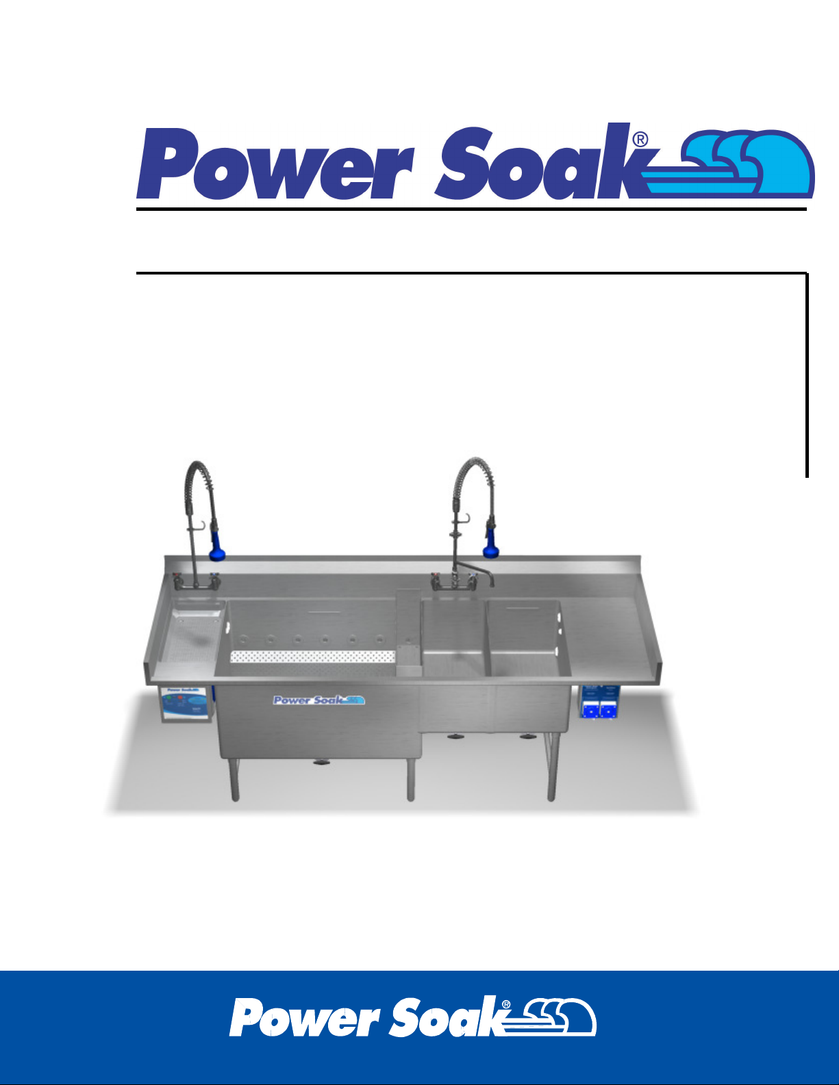
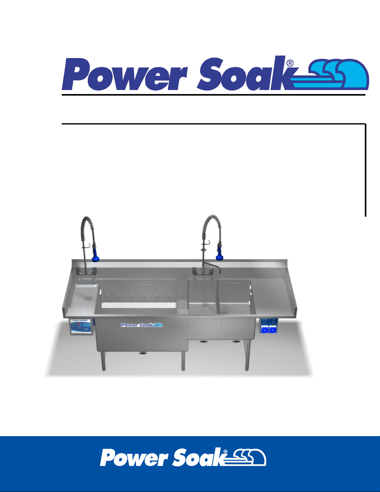
Installation Manual
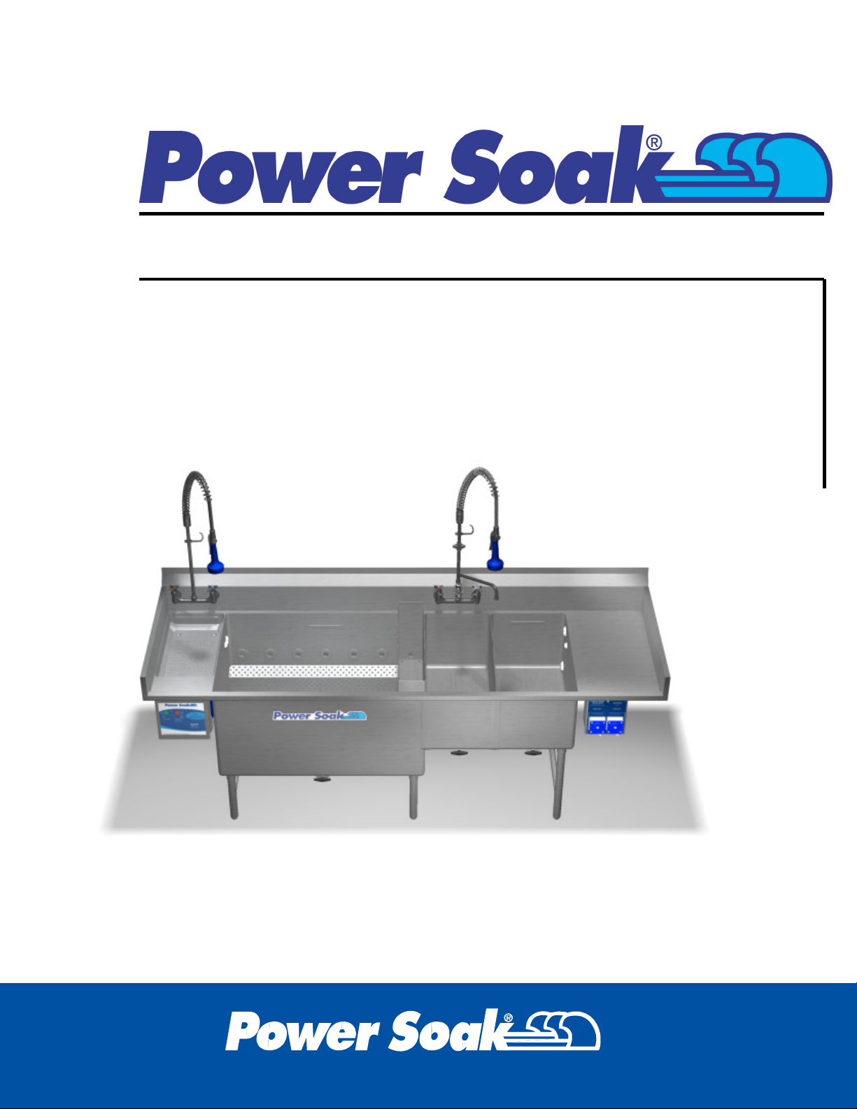
PS-200 & PS-201
Page 2

Page 3

Table of Contents
Pre-Uncrating Checklist ............................................... 1
Verifying System Requirements .................................. 2
Verifying System Direction ................................................................... 2
Verifying the Electrical Requirements .................................................. 2
Removal of Existing Unit ............................................. 3
Existing Supply Lines ........................................................................... 3
Existing Sink Removal ......................................................................... 3
Wall Preparation .................................................................................. 3
Pre-Plumbing ............................................................... 4
Supply and Waste Lines ...................................................................... 4
Grease Trap ......................................................................................... 4
Post-Uncrating Instructions .......................................... 5
Uncrating ..................................................................... 6
Remove From Crate ............................................................................ 6
Component Installation ................................................ 7
Install Sink Drains ................................................................................ 7
Install Legs ......................................................................................... 10
JBZ Joint Installation ................................................. 12
Test Fit ............................................................................................... 12
Mating and Sealing the Joint .............................................................. 12
Wiring Connections ................................................... 14
Machine Wiring .................................................................................. 14
Optional Wireless Remote Alert Light System ................................... 14
Optional Chemical Dispenser Wiring ................................................. 14
Faucet Installation .............................................................................. 15
Completing the Installation ......................................... 17
Final Installation Steps .............................................. 18
Machine Placement ........................................................................... 18
Downturned-Backsplash Z-Clip Installation ....................................... 18
Upturned-Backsplash Level Attach to the Wall .................................. 18
Seal around the Backsplash and Screws ........................................... 19
Rinse Riser and Anchor Installation ................................................... 19
Page 4

Plumbing Connections ....................................................................... 19
Electrical Connections ....................................................................... 20
Checking the Motor Rotation (“JOG” Feature) ................................... 20
Shelving ............................................................................................. 20
Validating the Installation ........................................... 21
Testing the Components ........................................... 22
Check for Leaks ................................................................................. 22
Check the Electrical Installation ......................................................... 22
Check Operation ................................................................................ 22
Check the Chemical Dispensing System ........................................... 22
Appendix.................................................................... 23
Page 5
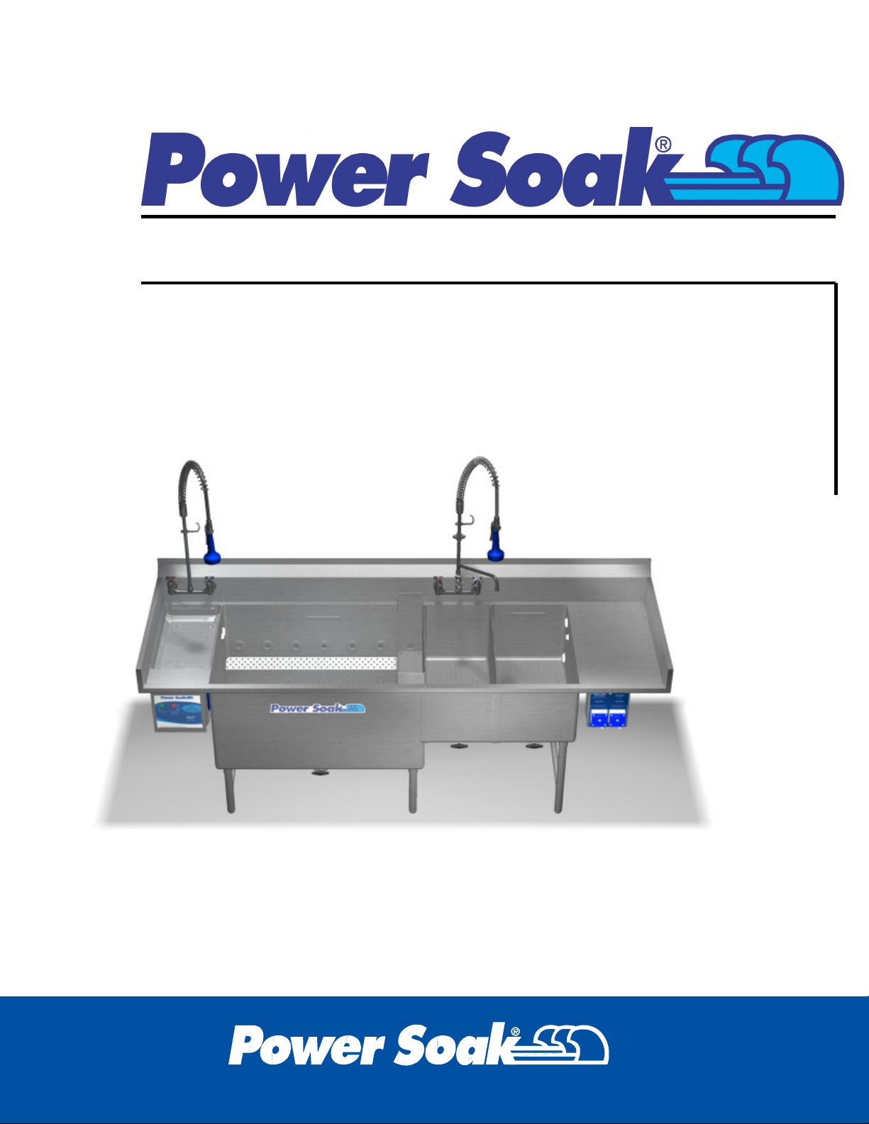
Pre-Uncrating Checklist
PS-200 & PS-201
1
Page 6
IMPORTANT
Verifying System Requirements
Prior to completely removing the Power Soak unit from the crate, it is necessary
to verify certain requirements. Remove only the lid of the crate at this time.
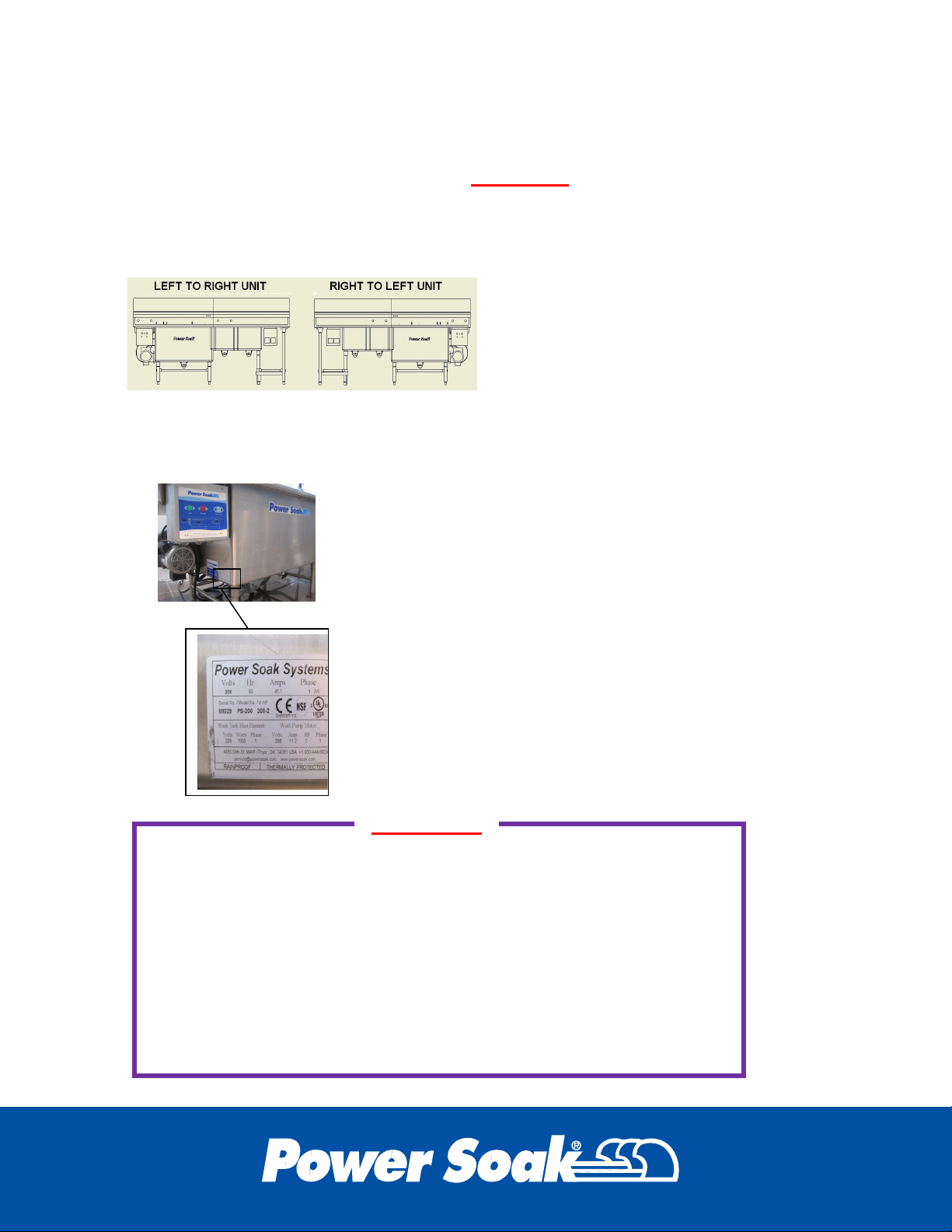
Verifying System Direction
The Power Soak can be built as a
“Left to Right” or as a “Right to Left”
configuration with a variety of
options. Look inside the crate and
verify that the configuration of the
machine matches the specifications
of the order description.
Verifying the Electrical Requirements
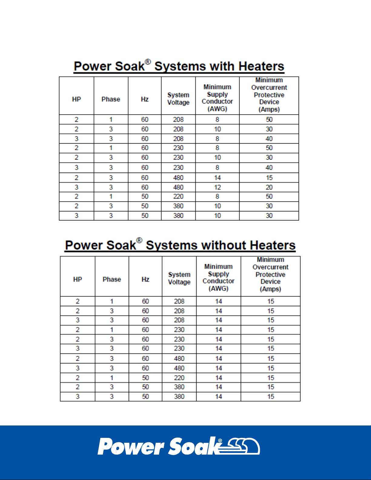
The electrical requirements for the machine are on
the machine identification tag located on the side
of the wash tank, next to the motor. The electrical
service in the facility where the machine is to be
installed must be rated for the capacity shown on
the identification tag. This machine will require a
permanently mounted disconnect that is in a
“liquid tight” enclosure. Do not use an in-line plug
for disconnecting the machine from the electrical
source. Contact a licensed and certified
electrician to make the enclosure installation if one
is not present. Use the tables in the appendix to
determine the appropriate breaker (overcurrent
protection) and wire size for the machine’s
electrical service.
WARNING: DO NOT connect the machine using a power cord and
plug or an extension cord of any kind.
WARNING: Kitchens are a wet environment which require all
electrical connections to be “liquid tight”.
Electrical installation must conform to all applicable local wiring codes.
All electrical connections must be “liquid tight” and readily accessible
for inspection after installation without moving the Power Soak
machine or any of its accessories.
2
Page 7

Removal of Existing Unit
If the new Power Soak is not replacing an existing sink, skip this section. If
the removal of an existing sink is necessary, continue with this section.
Existing Supply Lines
The water and electrical source must be shut off before disconnecting or
cutting the water or electric lines.
WARNING
Failure to shut off the electrical and water supply will result in personal injury,
including serious injury or death, and extensive equipment damage.
Disconnect any electrical cord that is connected to the existing sink. Cut
the cold and hot water lines as closely as possible to the fittings on the
existing sink.
IMPORTANT
Be sure to leave enough of the existing piping for the installation of new shutoff
valves. See “Pre-Plumbing” section for reference.
Existing Sink Removal
Detach any fasteners holding the existing sink in place and remove the
existing sink along with any shelves that may interfere with the installation
of the Power Soak. Discard all unwanted materials in an appropriate
container or disposal area.
Wall Preparation
Clean the wall(s) where the new Power Soak will be installed. Fill all
existing holes with an appropriate filler material. Be sure that any outlet
that will be covered by the sink has been disconnected and a water tight
cover has been installed over the opening.
3
Page 8
IMPORTANT
IMPORTANT
Pre-Plumbing
Supply and Waste Lines
The supply and waste lines must meet the following requirements:
• Hot and cold water supply must be ½” diameter or larger.
• Center lines of the hot and cold water supply must be 10” or less above
the floor to access the shutoff valves when the machine is installed.
• Waist drain must be 1-1/2” minimum diameter.
• Center line of the waste drain must be 11” or less above the floor to
allow the sink to drain properly.
Install new shutoff valves on the hot and cold water supply lines.
IT IS RECOMMENDED THAT ALL MACHINES BE INSTALLED USING
NEW ½” OR LARGER BALL-VALVE SHUT OFF VALVES.
Grease Trap
It may be necessary to relocate and/or replace the existing grease trap. Be
sure that the grease trap meets or exceeds the local plumbing codes.
WASTE PLUMBING MUST CONFORM TO LOCAL BUILDING CODES.
4
Page 9
Post-Uncrating Instructions
PS-200 & PS-201
5
Page 10
Uncrating
Remove From Crate
Remove the Power Soak from the shipping crate. Sharp staples and nails
are used to crate the machine and care must be taken in handling boards
and cardboard to keep from creating a puncture or injury to people or the
equipment. Discard the crating materials in an appropriate disposal area
or container.
Inspect the sink and packages to be certain that there was no damage
created by the shipping company. If there are signs of shipping damage,
contact the shipping company before proceeding.
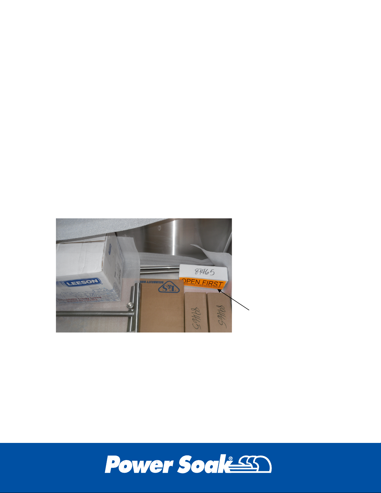
Remove the packages from the Power Soak tank and locate the box
labeled “OPEN FIRST”. This box will contain the fasteners and sealant
that will be required for assembly of the Power Soak.
6
Locate the box labeled
“OPEN FIRST”
to find fasteners and
sealant used for the
installation.
Page 11
Component Installation
IMPORTANT
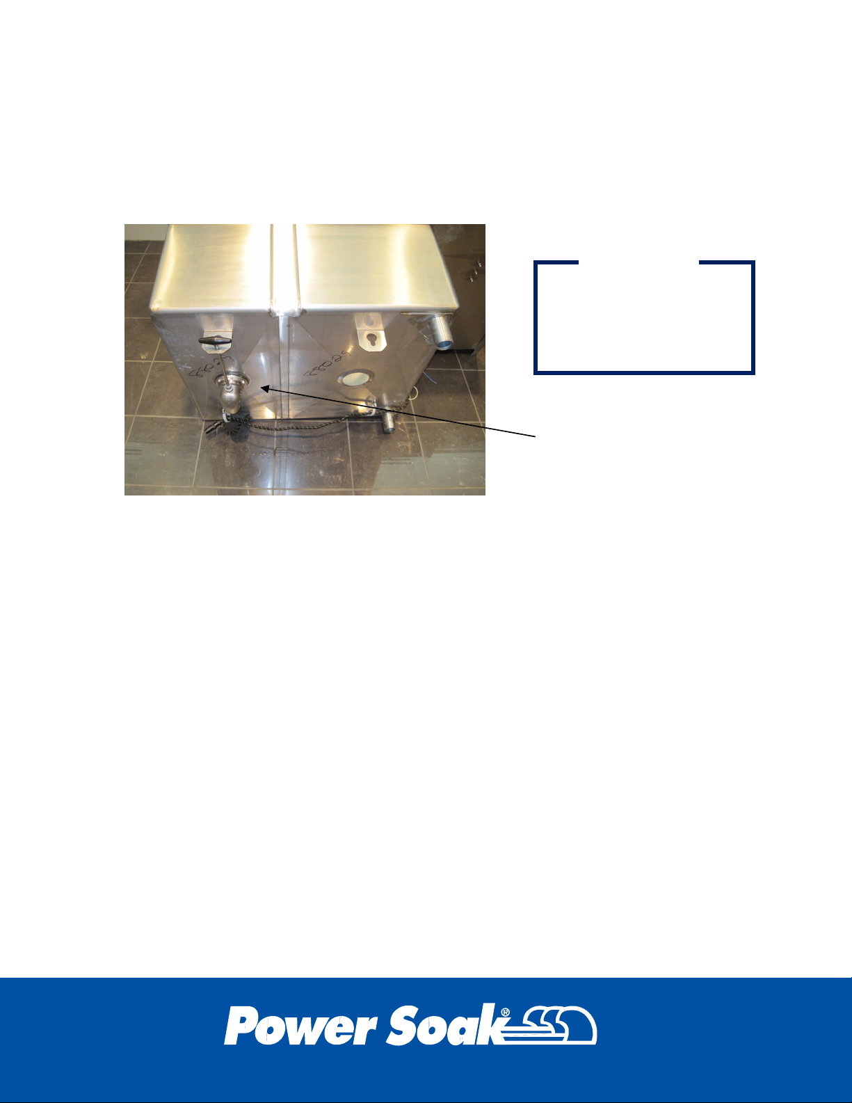
Lay the sink on its back to allow access to the bottom of the tanks. Be
careful to not let the sink assembly drop on the floor with an impact that
would damage the sink assembly or the floor. It may be necessary to
place some cardboard or tarp on the floor to protect the finish.
Do not bend the edge of
the backsplash when
laying the sink on its back
side.
DRAIN WITH BUILT-IN
VALVE IS INSTALLED
IN THE BOTTOM OF
The sink must be accessible from its top side and its bottom side in order
to install the accessories. Be aware that the backsplash is unsupported at
this time and can be bent out of shape by trying to support the entire
weight of the sink on the edge of the backsplash.
THE TANK
Install Sink Drains
There are three sink drains in the Power Soak that must be installed. The
drain with a valve built into the body is installed in the bottom of the tank
and oriented with the drain valve handle toward the front of the sink. Each
drain flange must be sealed to its mating surface in the sink.
7
Page 12
IMPORTANT
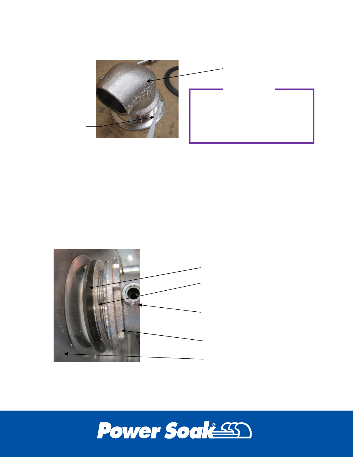
Apply a generous bead of a drain sealant around the lip of the drain body.
DRAIN BODY
THE RIM OF THE DRAIN MUST
SEAT ON THE SURFACE OF THE
APPROVED
DRAIN
SEALANT
The drains with built-in valves will be oriented with the handle connection
toward the front of the sink. From inside the sink, insert the drain through
the drain hole and seat the flange against the sheet metal surface of the
tank. Be sure that the sealant compresses to where the rim of the drain
actually touches the sheet metal surface of the sink. If the drain does not
touch the sink it will work loose and leak as the sealant compresses over
time.
From the outside of the tank place the rubber vibration ring over the
threaded body of the drain followed by the Teflon ring and then the drain
nut. Tighten the nut “hand tight” until the handle is installed.
SINK OR IT WILL WORK LOOSE
OVER TIME AND ALLOW WATER
TO LEAK AROUND THE DRAIN
8
RUBBER VIBRATION RING
TEFLON RING
HANDLE CONNECTION
ORIENTED TOWARD THE
FRONT OF THE MACHINE.
FLANGE NUT
BOTTOM OF SINK (Sink is laying
on its back side in this illustration)
Page 13
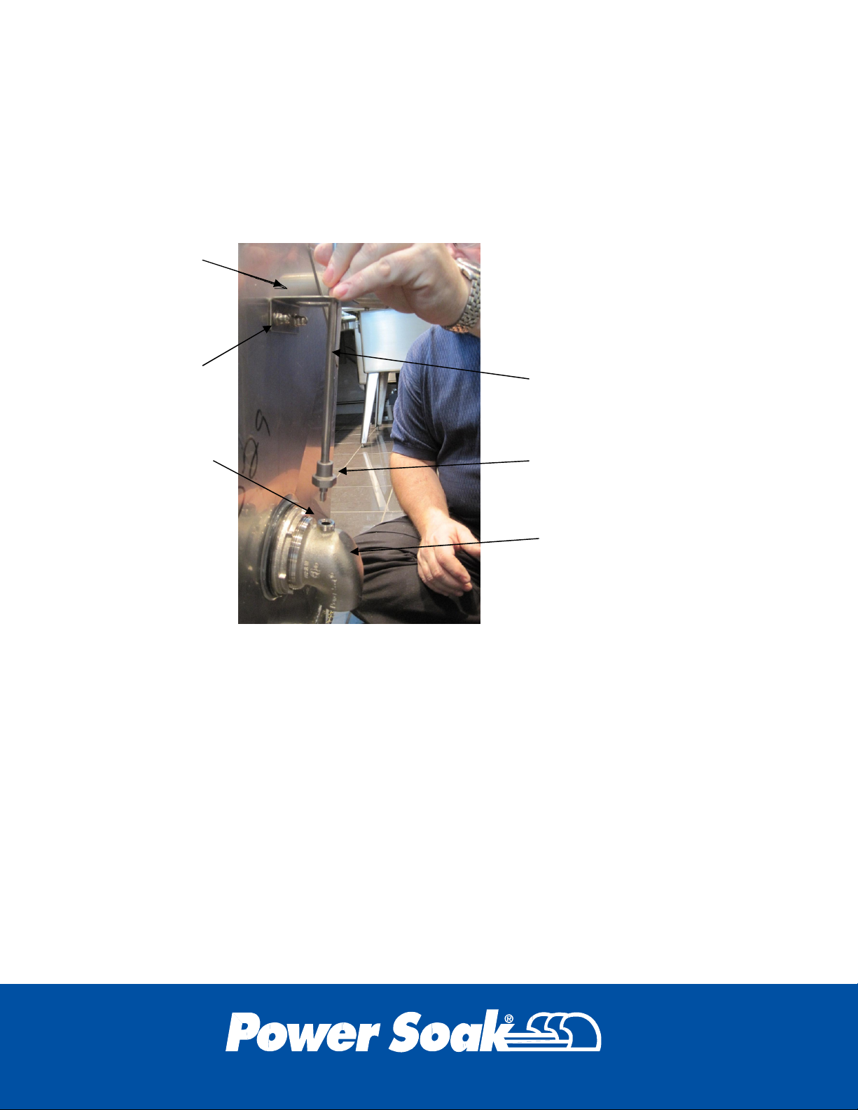
Using two nuts, attach the drain handle bracket to the studs on the bottom
LVE BODY
of the tank. Insert the drain valve handle through the bracket and into the
drain body. It may be necessary to rotate the handle a partial turn to align
the flats on the end of the handle shaft with the flats on the valve so that
the handle will fully insert into the valve. Secure the handle to the valve
body by screwing the handle nut onto the valve body connection.
HANDLE
BRACKET
NUTS
VA
CONNECTION
FOR HANDLE
While holding the drain body to prevent it from rotating, tighten the flange
nut with a wrench to firmly seat the nut against the rubber vibration ring
and the vibration ring against the surface of the sink (approximately ¼ turn
past “hand tight”). Wipe or trim the excess sealant from around the drain
flange inside the sink. Allow the sealant to dry before filling the sink with
water (see instructions on the side of the sealant container for drying time).
After the sealant has dried, fill the sink with water and check for leaks
around the drain.
HANDLE
HANDLE NUT
DRAIN
BODY
9
Page 14
Install Legs
The Power Soak is usually shipped without the leg assembly attached to
the machine. Different options have different types of leg assemblies.
Some leg assemblies are all welded together and others are pieces that
need to be assembled. If the leg set is welded together, skip to the section
labeled “Leg Set and Sink”.
Leg Set Assembly
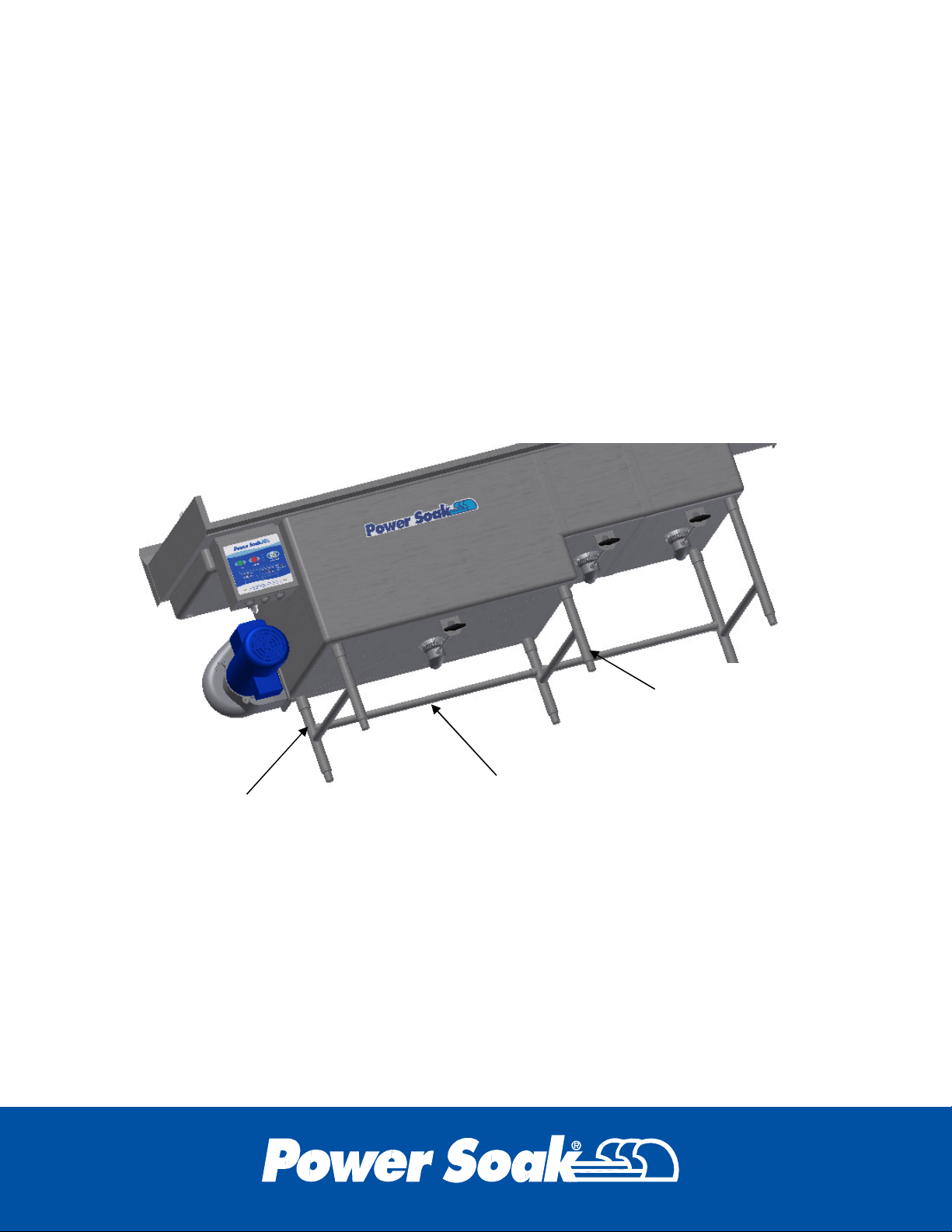
Locate the two leg end weldments and stretcher. The stretcher is the
horizontal tube that connects between the legs to provide lateral stability to
the legs. The long stretcher will be installed between the back legs of the
wash tank.
LEG END
WELDMENT
INSTALL THE LONG STRETCHER
INSTALL THE SOCKETS ABOVE
THE WELD JOINT PRIOR TO
INSERTING THE LEG WELDMENT
INTO THE SOCKETS ON THE
BOTTOM OF THE SINK.
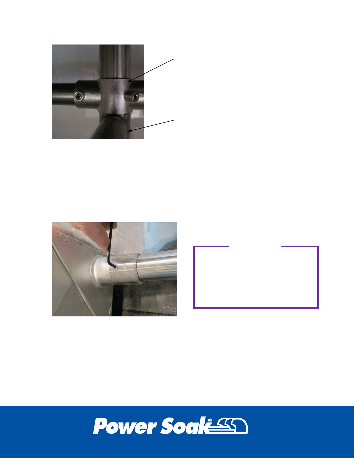
Orient the stretcher socket with the set screw facing toward the interior of
the sink and then slide the stretcher sockets over the top of the leg sets so
that the stretcher will be positioned above the welded joint of the leg when
the legs are assembled onto the sink. Install the long stretcher and the
other stretcher between the leg sets by inserting it into the sockets before
inserting the legs into the sockets on the bottom of the tanks.
UNDER THE WASH SINK.
10
Page 15
IMPORTANT
SET SCREWS ARE ORIENTED
TOWARD THE INTERIOR OF
THE SINK AND THE SOCKET IS
ON TOP OF THE WELDED
STRETCHER
WELDED STRETCHER
Leg Set and Sink
Insert the leg assembly into the sockets on the bottom of the sink. Insert
the leg set into the sanitizer sink (sanitizer sink is an option and may not be
included). Be sure that all the legs are seated in the bottom of the sockets.
Use an allen wrench (5/32) to tighten the set screws in all of the sockets.
After tightening the set screws, apply silicone sealant (supplied with the
machine) to the set screw openings in order to seal the openings in a clean
and sanitary manner.
AFTER TIGHTENING THE SET
SCREWS, FILL THE OPENINGS IN
A CLEAN AND SANITARY
MANNER WITH THE SILICONE
SEALANT THAT IS SUPPLIED
WITH THE MACHINE
Adjusting the Feet
Use a tape measure and adjust the feet to the approximate height required.
Turn the hexagon foot clockwise to shorten the height of the sink or
counterclockwise to raise the height of the sink. Final adjustment of the
feet will be done after the sink is in the installed location. Set the sink and
leg assembly upright on its feet.
11
Page 16
JBZ Joint Installation
If the unit is shipped in one piece, skip this section. If the unit is shipped as
two separate pieces, continue with this section.
Test Fit
Dry fit the two sections of the sink together to be sure that the joint has not
been damaged in shipping. The lip of the rinse tank will slide over the
edge of the wash tank.
Check the alignment and fit of the two sections. It may be necessary to
adjust the leveling feet to achieve a correct fit. Ensure that all the feet are
adjusted to firmly contact the floor.
Separate the two sections in order to apply sealant to the joint.
Mating and Sealing the Joint
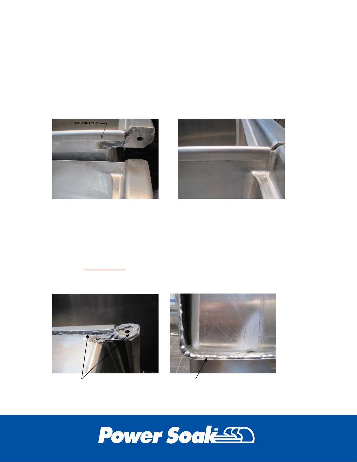
Apply the grey-colored NSF approved sealant (supplied with the unit) to
the underside of the JBZ lip and all interior surfaces of the wash tank trim
plate.
SEALANT APPLIED TO
UNDERSIDE OF JBZ JOINT AND
FACE OF THE END PLATE
12
SEALANT APPLIED TO INTERIOR
SURFACE OF TRIM PLATE
Page 17
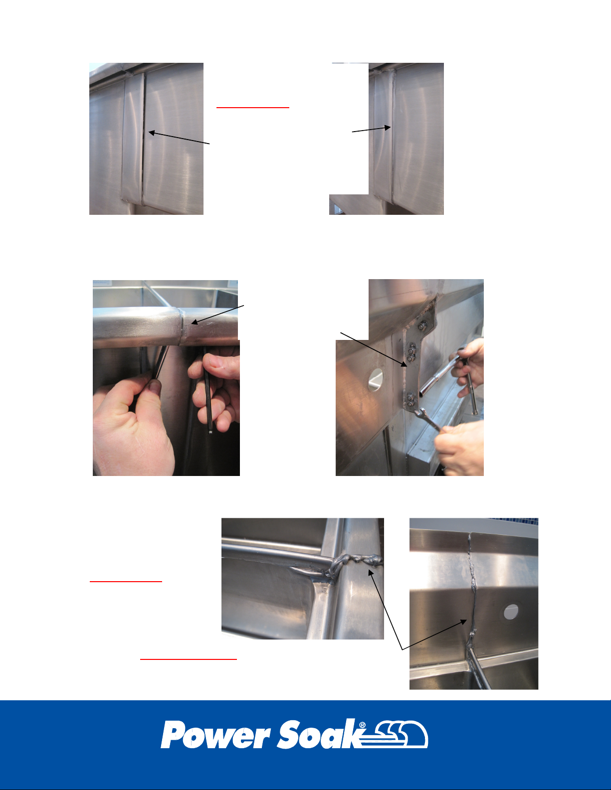
Reassemble the two
sections. Apply a bead of
grey-colored NSF
approved sealant (supplied
with the unit) in the gap
between the rinse sink and
the trim plate. Seal the
entire joint to keep liquids
from entering.
Bolt the channel rim and backsplash together using the nuts and bolts
provided with the unit.
BOLT THE JOINT
TOGETHER UNDER
THE FRONT RIM
AND BEHIND THE
BACK SPLASH.
Seal the backsplash,
channel rim, and all
the gaps between the
two sinks with the
grey-colored NSF
approved sealant that
is supplied with the
unit.
APPLY THE GREY-COLORED NSF APPROVED SEALANT
TO ALL THE SINK JOINTS AND WIPE THE EXCESS AWAY
LEAVING A SMOOTH SANITARY JOINT.
13
Page 18
IMPORTANT
Wiring Connections
Machine Wiring
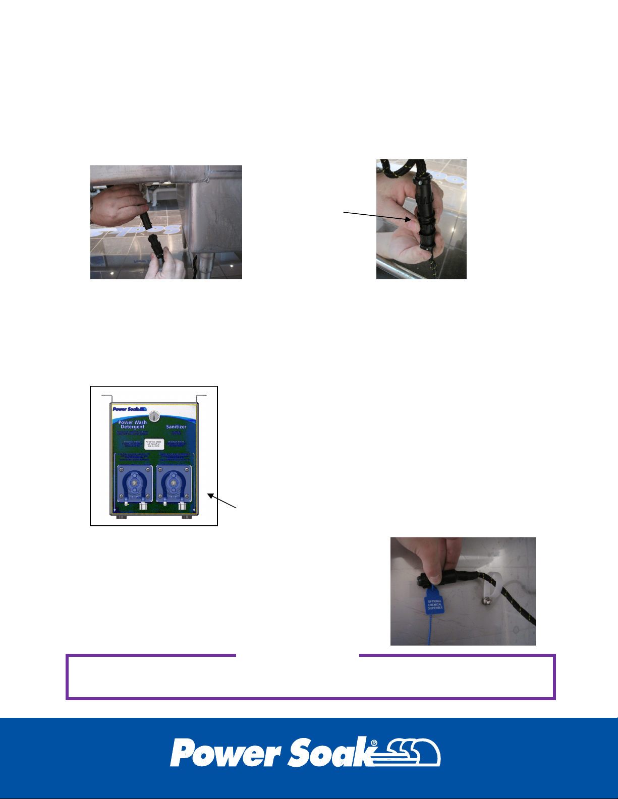
Locate the two halves of the wiring harness and inspect them to be sure
they are clean and not damaged. Insert the two halves together and hand
tighten the threaded collar.
HAND
TIGHTEN
THE COLLAR
Optional Wireless Remote Alert Light System
If the Power Soak unit was purchased with the Wireless Remote Alert Light
System, refer to the instructions provided with the light system to complete
the wiring for this devise.
Optional Chemical Dispenser Wiring
If installing any chemical dispensing system that
is not a Power Soak® brand chemical dispenser,
follow the manufacturer’s installation guide, and
skip this section.
If the unit being installed is supplied with the
optional Power Soak® brand chemical dispenser,
proceed with this section.
The Power Soak® chemical dispensing unit must be
bolted to the underside of the front rim and have the
electrical connector attached to the back of the
chemical dispenser enclosure. The chemical
delivery hoses must be installed from the dispenser
to the wash tank and sanitizer tank chemical
injectors. The hoses may follow along the wire
harness and loosely hung with zip-type wire ties.
The chemical supplier must finalize the setup of the chemical dispensing system.
Power Soak® brand chemical dispenser is
shown here
14
Page 19
Faucet Installation
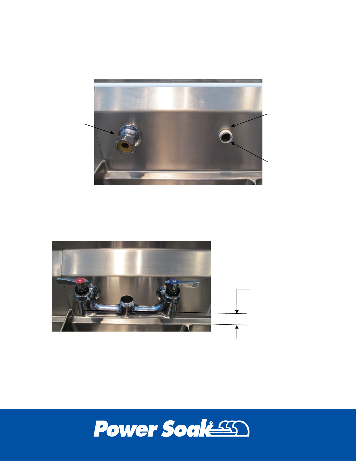
Open the faucet package and locate the water connection elbows, faucet
body and escutcheon assemblies. Apply Teflon tape to the threads of the
elbows and insert them though the backsplash of the sink.
Escutcheon
screwed onto
the elbow
Loosely fit the escutcheons to the elbows and the faucet body. When the
alignment of the body with the sink is confirmed, tighten the escutcheons
onto the elbows and faucet body. From the back side of the backsplash,
tighten the brass nuts on the elbows when the faucet body is parallel with
the rim of the sink.
Elbow inserted
from the back
side of the
backsplash
Wrap the elbow
threads with
Teflon tape
Faucet must be parallel
with the drain board or rim
of the sink
Complete the faucet assembly according to the manufacturer’s instructions
which are included with the faucet. Attach water lines to the faucet so that
the lines extend below the sink. This will make the plumbing easier to
complete when the machine is placed against the wall.
15
Page 20

Intentionally blank page
16
Page 21
Completing the Installation
PS-200 & PS-201
17
Page 22

IMPORTANT
Final Installation Steps
Machine Placement
Position the Power Soak so that the back splash rests against the wall and
is placed according to the floor plan or customer’s selected location.
Examine the drain and water supply lines to determine that the plumbing
can be completed when the Power Soak is in the final location. Verify that
the plumbing from the faucet can be reached with the sink against the wall.
Downturned-Backsplash Z-Clip Installation
If the Power Soak® system has an upturned backsplash, skip this step.
If the Power Soak® system has a backsplash that is downturned, attach the
provided Z-Clips to the wall using the following procedure. Using a level,
adjust the feet on the Power Soak until the front rim and the rear rim of the
sink are level. The sink must also be level front to back. Measure from the
floor to the top edge of the backsplash, and then move the sink away from
the wall. Locate Z-Clips by marking a level line on the wall approximately
1/16" to 3/32" below the height of the backsplash top edge. Locate the wall
studs and mark the locations. Align top edge of Z-Clip(s) to the marked
line and securely fasten the Z-Clips to the wall, using fasteners provided.
Install screws directly to the walls' studs whenever possible. The Z-Clips
should be space as evenly as possible. Move the sink to the wall and lift
the back edge over the Z-Clips.
Upturned-Backsplash Level Attach to the Wall
If the Power Soak® system has a downturned backsplash, skip this step.
Using a level, adjust the feet on the Power Soak until the front rim and the
rear rim of the sink are level. The sink must also be level front to back.
Locate the wall studs and mark their location on the top edge of the back
splash. Measure down ¾” from the top of the backsplash and then drill ¼”
diameter holes through the back splash in line with the center of the studs.
Use the #10 stainless steel screws (included with the Power Soak) to
attach the Power soak directly to the wall.
The Power Soak sink assembly must be level from side to side and
front to rear with all the feet making firm contact with the floor.
18
Page 23
Seal around the Backsplash and Screws
IMPORTANT
Examine the installation to see that the wall and backsplash are clean and
free of dust and oils. Seal the top and sides of the backsplash to the wall
using the clear NSF approved sealant provided with the Power Soak. Seal
around the screw heads to be sure they do not allow water to leak behind
the backsplash. Wipe off all excess sealant leaving a smooth, clean and
sanitary bead of sealant on all the edges.
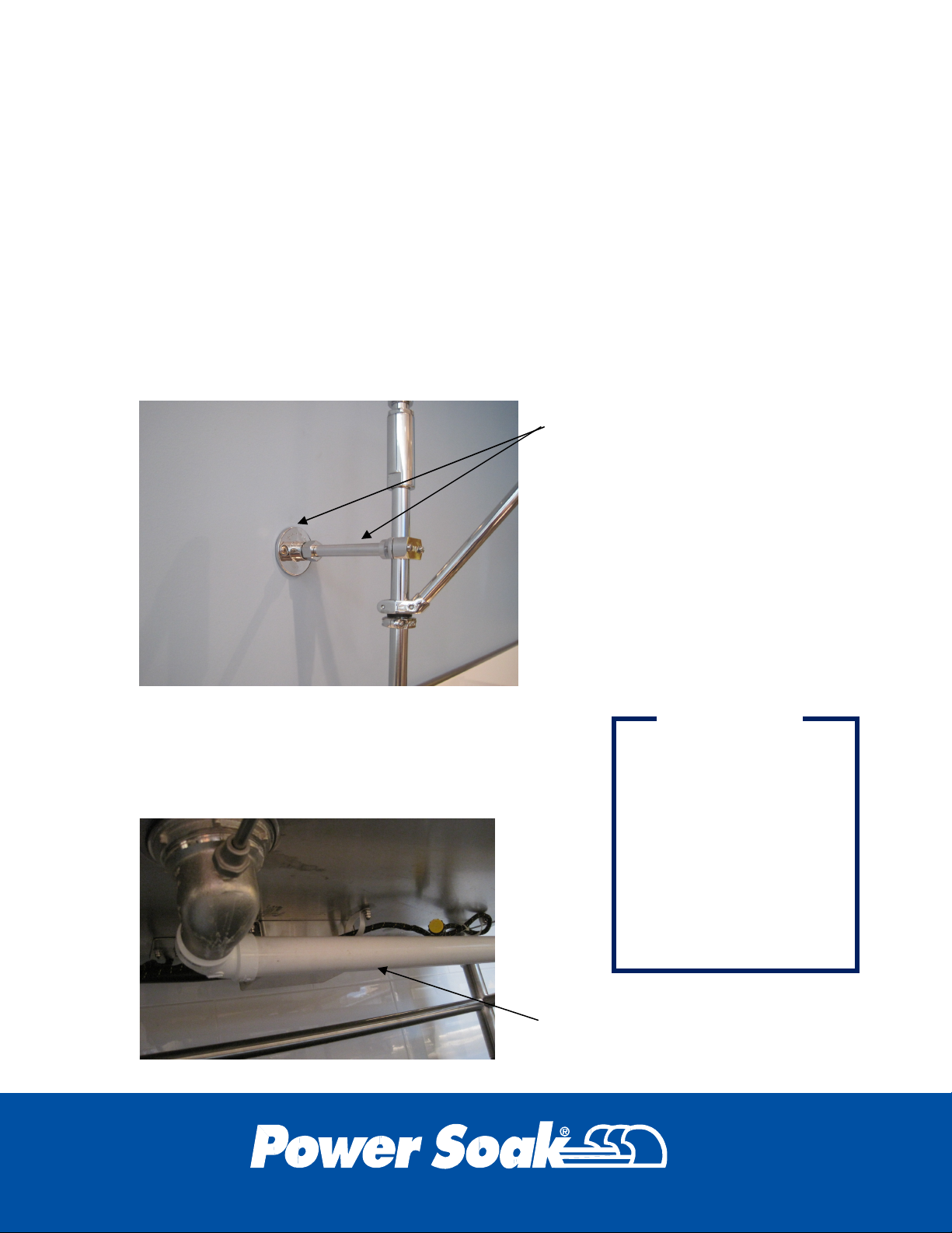
Rinse Riser and Anchor Installation
Follow the faucet manufacturer’s directions on the assembly of the faucet
and riser. Anchor the riser supports to the wall using the flange plate
provided with the riser assembly. It may be necessary to cut the support
rods to a shorter length in order to fit between the wall and the riser.
Cut the riser support rods
to the proper length and
attach flanges to the wall
Plumbing Connections
Connect the water supply lines to the faucet.
Connect all the drains to the waste drain connection.
Complete the connection
of all drains and water
supply lines
INSTALLER IS
RESPONSIBLE FOR
ALL PLUMBING TO
CONFORM TO LOCAL
BUILDING CODES
WHICH MAY BE
DIFFERENT FROM
ILLUSTRATIONS
SHOWN IN THIS
MANUAL
19
Page 24
IMPORTANT
Electrical Connections
The final electrical connections between the Power Soak and the electrical
supply must be made by a licensed electrician. The Power Soak has
several options for motors and heater. Review the information tag for
determining the specific requirements of the machine being installed (see
Verify the Electric Requirements section of this instruction booklet).
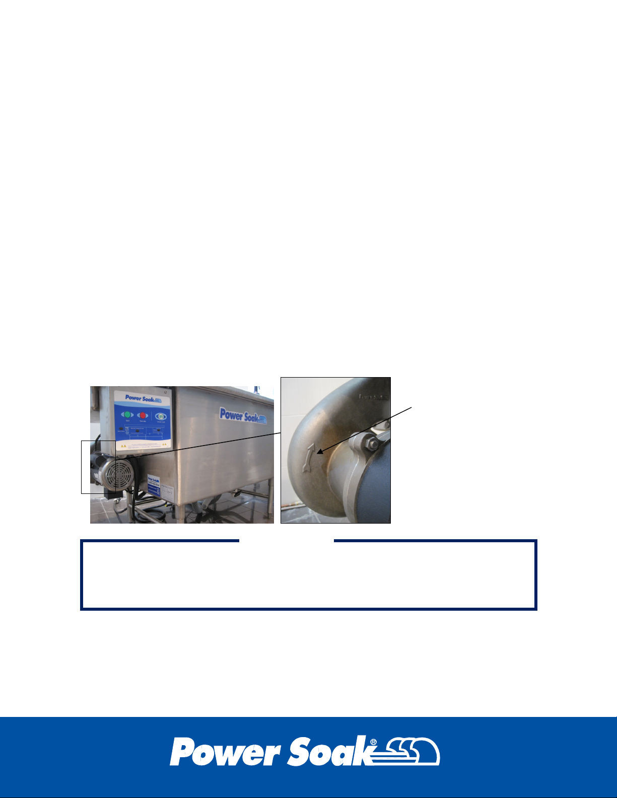
Checking the Motor Rotation (“JOG” Feature)
The motor must rotate in the correct direction in order for the Power Soak
to function properly. An arrow indicating the direction of rotation is located
on the pump housing. The control unit has a feature that allows the motor
to be “jogged” for checking the rotation even if the wash tank is empty.
Press and hold the green START button for 5 to 10 seconds and watch the
fan blades inside the motor fan cover. After holding the start button for the
5 to 10 second delay, the motor will start for a few rotations and
automatically stop if the wash tank is empty. If the wash tank is full of
water the motor will continue to run even if the direction of rotation is not
correct. When the wash tank is full, the red STOP button must be pressed
to stop the motor. Running the motor in the wrong direction does not
damage the motor or pump, but the pump will not circulate water in the
wash tank correctly.
Arrow indicating the
direction of rotation is
located on the pump
housing
THE MOTOR MUST ROTATE IN THE CORRECT DIRECTION FOR THE
MACHINE TO OPERATE PROPERLY. USE THE “JOG” FEATURE TO
CHECK THE MOTOR ROTATION
Shelving
Reinstall any shelving that was removed for convenience of installation. If
the shelving is damaged or corroded, it is recommended that the shelving
be replaced.
20
Page 25
Validating the Installation
PS-200 & 201
21
Page 26
IMPORTANT
Testing the Components
Check for Leaks
• Turn on the water supply and inspect all joints for leaks.
• Close the drain valve(s), fill the sink(s) with water and inspect the
drain fittings for leaks.
• Open the drain valve(s) and inspect the drain joins for leaks as the
water is draining from the sink.
Check the Electrical Installation
• Verify that there are no loose wires or open electrical enclosure.
• Fill the wash tank with water and press the START button to see
that the motor will start. Have a qualified electrician verify that the
amp draw on the electrical supply is within the specifications on the
identification tag.
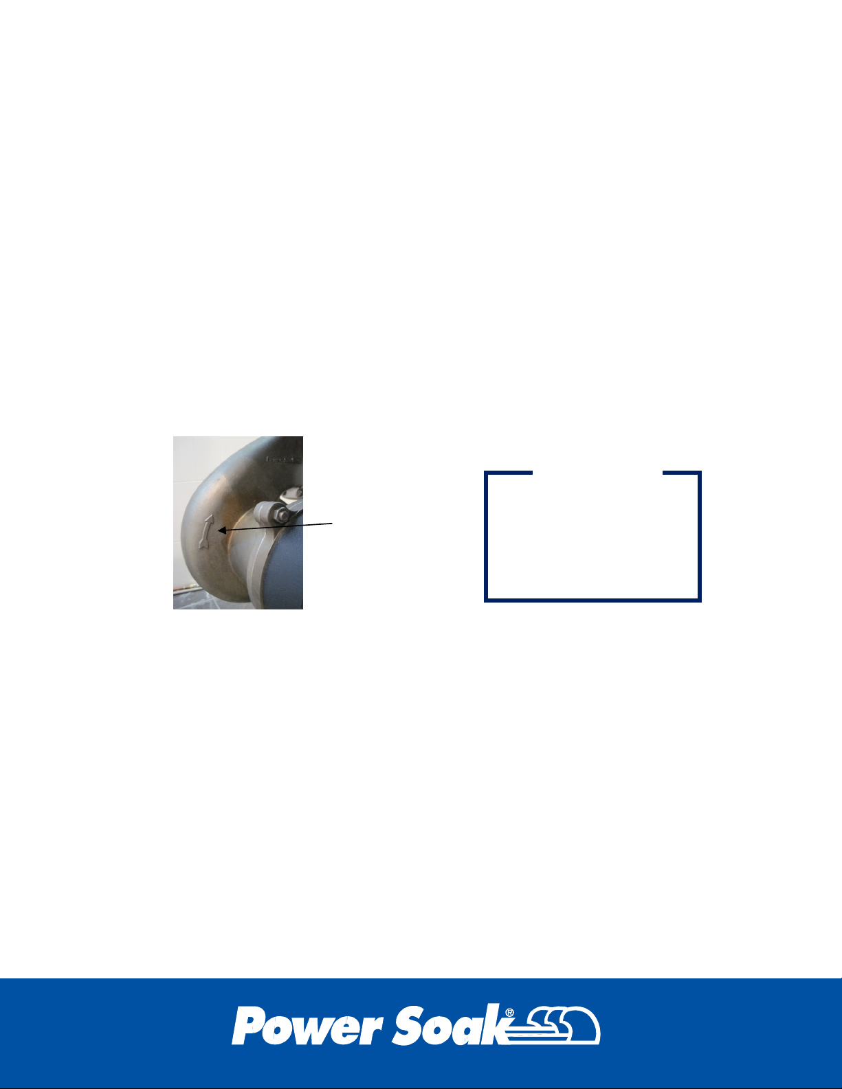
• Check motor rotation for the correct direction as indicated by the
arrow on the pump housing.
MOTOR ROTATION
Direction of
rotation arrow
MUST BE THE
CORRECT DIRECTION
FOR THE MACHINE TO
OPERATE CORRECTLY
Check Operation
• Open each faucet knob and verify that water flows from each hand
control. Verify that hot and cold water are running from the correct
hand control.
• With the water valves open, turn the center knob to see that it will
shut off flow to the faucet and that the hand sprayer is still
functional.
Check the Chemical Dispensing System
The Chemical Dispensing System must be checked by a representative of
the manufacturer. It will need to be verified that the proper amount of
chemical is being dispensed and that the proper chemical concentration is
maintained during operation.
22
Page 27
Appendix
23
Page 28

Power Soak is a registered trademark of Cantrell Industries, Inc.
The Power Soak concept and design is fully patented.
Power Soak Systems. Inc.
903 East 104th Street, Suite 130
Kansas City, MO 64131
Phone (816) 222-2400 Fax (816) 222-2419
(800) 444-9624
www.powersoak.com
Part#: 29222
Rev: A
Rev Date: 2/27/2013
24
 Loading...