


Service Manual
PS-225

Intentionally bank page

|
Table of Contents |
|
Introduction – Section 1 ............................................... |
2 |
|
1.0 |
Product Introduction....................................................................... |
2 |
1.1 |
General Description ....................................................................... |
2 |
Messages – Section 2.................................................. |
3 |
|
2.0 |
Explanation of Warning Messages ................................................ |
3 |
2.1 |
Danger ........................................................................................... |
3 |
2.2 Warning ......................................................................................... |
3 |
|
2.3 |
Chemical Hazard ........................................................................... |
3 |
2.4 |
Personal Injury Hazard .................................................................. |
3 |
Detergents and Sanitizer – Section 3 .......................... |
4 |
|
3.1 |
Detergents ..................................................................................... |
4 |
3.2 |
Sanitizers ....................................................................................... |
4 |
3.3 |
Factory Assistance......................................................................... |
4 |
Preventative Maintenance - Section 4 ......................... |
5 |
|
4.0 |
Maintenance .................................................................................. |
6 |
4.1 |
Daily............................................................................................... |
6 |
4.1a Clean the liquid level sensors................................................... |
6 |
|
4.2 |
Monthly .......................................................................................... |
6 |
4.2a Clean the motor fan shroud...................................................... |
6 |
|
4.2b Clean the Heating Element ...................................................... |
6 |
|
4.3 |
Quarterly ........................................................................................ |
6 |
4.3a De-lime the wash sink .............................................................. |
6 |
|
Control Panel Lights - Section 5 .................................. |
7 |
|
5.1 |
Control Panel Overlay.................................................................... |
8 |
5.2 Light Illumination Code .................................................................. |
9 |
|
5.3 |
Green Status Light ......................................................................... |
9 |
5.4 |
Blue Wash Tank Light.................................................................. |
10 |
5.5 |
Red Sanitizer Tank Light.............................................................. |
10 |
5.6 |
Green Unload/Load Light............................................................. |
10 |
5.7 |
Error Codes ................................................................................. |
11 |
Liquid Level Error ........................................................................... |
11 |
|
Temperature Sensor Error ............................................................. |
11 |
|
Over Current Error ......................................................................... |
11 |
|
Over Temperature Error ................................................................. |
11 |
|

Current Sensor Error...................................................................... |
11 |
|
Membrane Error ............................................................................. |
12 |
|
Control Panel Components - Section 6 |
|
|
Authorized Personnel Only ........................................ |
13 |
|
6.0 |
Universal Programming Module (UPM) ....................................... |
14 |
6.1 |
Programming Interface ................................................................ |
15 |
6.2 |
Communication Port .................................................................... |
16 |
6.3 |
Alert Lights................................................................................... |
16 |
6.4 |
Triac Relay................................................................................... |
16 |
6.5 |
Power Transformer ...................................................................... |
18 |
6.6 |
Contactor ..................................................................................... |
19 |
6.7 |
Load Sensor ................................................................................ |
19 |
6.8 |
Fuse Holder, Terminal Blocks and Jumpers ................................ |
20 |
6.9 |
Push Button Membrane ............................................................... |
21 |
Electrical Components - Section 7 |
|
|
Authorized Personnel Only ........................................ |
23 |
|
7.1 |
Pump Motor ................................................................................. |
24 |
7.2 |
Motor Thermo-disc....................................................................... |
24 |
7.3 |
Heating Element .......................................................................... |
25 |
7.4 |
Heating Element Thermo-disc ..................................................... |
27 |
7.5 |
Thermistor.................................................................................... |
27 |
7.6 |
Liquid Level Sensors.................................................................... |
28 |
Assembly Procedures - Section 8 |
|
|
Authorized Personnel Only ........................................ |
29 |
|
8.1 |
Motor and Pump .......................................................................... |
30 |
8.1a Disassembly........................................................................... |
30 |
|
8.1b Inspection............................................................................... |
30 |
|
8.1c Assembly................................................................................ |
31 |
|
8.2 |
Heating Element .......................................................................... |
32 |
8.2a Disassembly........................................................................... |
32 |
|
8.2b Inspection............................................................................... |
32 |
|
8.2c Assembly................................................................................ |
33 |
|
8.3 |
Sensor Pad .................................................................................. |
34 |
8.3a Disassembly........................................................................... |
34 |
|
8.3b Inspection............................................................................... |
34 |
|
8.3c Assembly................................................................................ |
34 |
|

8.4 |
Chemical Dispenser (Optional) .................................................... |
34 |
Troubleshooting - Section 9 ....................................... |
35 |
|
9.1 |
The pump will not start when the green “Start” button is pushed. 36 |
|
9.1a. Control panel Status (green) light is not on or flashing.......... |
36 |
|
9.1b. Control panel Status (green) light is flashing and Wash Tank |
||
|
(blue) light is on. ................................................................... |
36 |
9.1c. Control panel Status (green) light is flashing and Sanitize Tank |
||
|
(red) light is on. ..................................................................... |
36 |
9.1d. Control panel Status (green) light is blinking with a pattern of |
||
|
long and short flashes........................................................... |
37 |
9.1e. All of the lights on the control panel and all of the Alert Lights |
||
|
are flashing. .......................................................................... |
37 |
9.2 |
Motor starts, but makes noise. ..................................................... |
37 |
9.3 |
Motor starts, but no water flows in the wash tank. ....................... |
38 |
9.4 |
The control circuit fuse “blows” when the power is turned on. ..... |
38 |
9.5 |
The lights indicate that the tank is empty when it is actually full. . |
38 |
9.6 |
The water gets too hot and stops the machine. ........................... |
39 |
9.7 |
The chemical dispenser pump runs, but does not pump the |
|
|
chemical. .................................................................................... |
39 |
Parts Lists – Section 10 ............................................. |
41 |
|
10.1 Motor and Pump Assembly........................................................ |
42 |
|
10.1a Parts list ............................................................................... |
42 |
|
10.1b 60 Hz Motor and Impeller ..................................................... |
43 |
|
10.1c 50 Hz Motor and Impeller ..................................................... |
43 |
|
10.1d Pump Parts Common to all Assemblies ............................... |
43 |
|
10.1e Seal Kit................................................................................. |
43 |
|
10.2 Heater & Sensor Block............................................................... |
44 |
|
10.3 Control Panel ............................................................................. |
45 |
|
10.4 Decal Locations and Part Numbers. .......................................... |
46 |
|
10.4a Unit with Left to Right Work Flow ......................................... |
46 |
|
10.4b Unit with Right to Left Work Flow ......................................... |
46 |
|
Appendix.................................................................... |
49 |
|
Other PS225 Manuals and Related Component Manuals ................. |
50 |
|
Wiring Diagrams ................................................................................ |
50 |
|
Electric Wiring Diagram – Single Phase......................................... |
51 |
|
Electric Wiring Diagram – 3 Phase................................................. |
52 |
|
AWI Insert Diagram............................................................................ |
53 |
|

Intentionally blank page

SECTIONS 1, 2 & 3
PS-225
1

Introduction – Section 1
1.0 Product Introduction
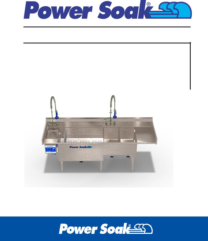
The Power Soak pot, pan and utensil washing system will provide years of dependable, efficient and trouble-free service. Every system is manufactured to last, with only highquality, heavy-duty, 14 gauge stainless steel used in its construction. All electrical components used in a Power Soak system are of the highest quality. The faucets and drains are designed for quick filling and emptying of the system's tanks.
Most Power Soak systems are provided with a 3 year parts and labor warranty. To inquire about the warranty status of a PS-225 Power Soak, please call the following number and have the serial number of the machine available at the time of the call:
Power Soak Systems
(800) 444-9624
The people at Power Soak Systems take pride in manufacturing the Power Soak equipment and are committed to standing behind Power Soak customers and products 100%.
1.1 General Description
The Power Soak PS225 can be built with many variations to meet the needs of Power Soak customers. The illustrations shown in this document cannot match all the possible machine configurations, however; the information will apply even if a machine does not match the illustration. The general configuration of a machine will start the work flow in the scraping area and/or wash tank and finish in a sanitize tank and/or on a drain board. The units that start with the scraping area and/or wash tank on the left are referred to as a “left to right” or “left hand” unit. A “right to left” or “right hand” unit will start with the scrap area and/or wash tank on the right hand side.
2
Messages – Section 2
2.0 Explanation of Warning Messages
Be sure to read, understand and follow all DANGER, WARNING, and CAUTION messages located in this document and on the equipment. These messages are used to identify areas of the machine that are harmful.
2.1 Danger
Personal Injury and Property Damage hazard. Will result in serious injury or death.
Will cause extensive equipment damage
2.2 Warning
Property Damage Hazard.
Will result in property or equipment damage.
2.3 Chemical Hazard
Will result in serious injury or death.
Instructions, labels and Material Safety Data Sheets (MSDSs) are to be supplied with all detergents and sanitizing chemicals. The manufacturers, importers and distributors of the cleaning chemicals are responsible for providing this information.
Power Soak Systems, Inc. is not a chemical manufacturer, importer or distributor. Power Soak Systems, Inc. can assist the chemical representative but will not make specific brand recommendations.
2.4 Personal Injury Hazard
Hazard from sharp objects.
Will result in serious injury or death.
3

Detergents and Sanitizer – Section 3
3.1 Detergents
Power Soak machines require a low-foaming, metal/aluminum-safe detergent. The detergent should have good grease cutting abilities and pH level that is safe for human contact. Improper detergents may damage the equipment. Use of the correct detergent in the Power Soak PS-225 is critical to its washing performance. If there are problems with cleaning results, please contact Power Soak Systems (1-800-444-9624).
Detergents with high or low pH level will damage the equipment and be harmful to human contact. Consult with a chemical manufacturer representative for recommendations on the selection of detergents.
3.2 Sanitizers
A "chemical sanitizing" method is used in the Power Soak system. There are a number of products on the market that work well in this application. A chemical sales representative should assist in selecting the proper sanitizer for each application. Check with a cleaning chemical provider to determine the detergent concentration, sanitizer "parts per million" (ppm) and sanitizer submersion times that will meet local health codes.
3.3 Factory Assistance
If a chemical sales representative is having difficulty selecting a detergent or sanitizer, or if there are poor results with the chemicals that have been recommended, please contact a Power Soak representative at:
1-800-444-9624.
4
Preventative Maintenance - Section 4
PS-225
5

4.0 Maintenance
Power Soak machines require minimal preventive maintenance. To ensure that the Power Soak PS-225 remains reliable, the following tasks should be completed at the intervals shown in this section.
4.1 Daily
4.1a Clean the liquid level sensors - The liquid level sensors are located on the side walls of the wash and sanitizer tanks (see section 7.4). They are white plastic discs with metal centers. The faces of the sensors need to be cleaned with a washcloth and soapy water. Regular cleaning will prevent a build-up of difficult to remove chemicals and debris.
The liquid level sensors must be cleaned regularly in order for the machine to operate correctly. Dirty sensors will allow the pump motor to operate without water in the wash tank, which will cause serious damage to the unit.
4.2 Monthly
4.2a Clean the motor fan shroud - The motor fan shroud is the "vented" cover located at the end of the motor closest to the control panel. Shut off the electrical supply at the electrical circuit breaker located in the wall mounted enclosure. Clean the pump motor fan shroud with a stiff bristle brush and a vacuum. If a brush and vacuum are unavailable, clean the shroud with a damp, soapy cloth. This will prevent grease and dust from accumulating in the openings of the cover and obstructing the airflow that cools the motor.
4.2b Clean the Heating Element - Shut off the electrical supply at the system’s electrical circuit breaker located in the wall mounted enclosure. Remove the cover plate located in the slanted surface of the back wall of the wash tank. Remove debris that has collected in and around the heating element. Install the cover plate when cleaning is completed. The cover plate must be installed after cleaning to prevent foreign objects from entering the pump suction and causing damage to the pump.
Failure to shut off the electrical supply will result in personal injury, including serious injury or death, and extensive equipment damage.
4.3 Quarterly
4.3a De-lime the wash sink - Select a de-liming agent that is safe for stainless steel sinks and follow the instructions on the package for mixing and fill the tank with water. Turn on the pump motor to circulate the mixture in the tank and pump manifolds.
6
Control Panel Lights - Section 5
PS-225
7

5.1 Control Panel Overlay
The Control Panel Overlay is bonded to the surface of the enclosure door and conceals the membrane that contains the push buttons and lights. The panel lights are used to indicate conditions that have been detected by the operating program. The lights on the face of the control panel operate in conjunction with the Alert Light System located on the bottom surface of the control box (lights that shine on the floor). There are some conditions that are indicated by the control panel lights which are not part of the Alert Light System. The operator should review the control panel lights when determining the operating situation of the machine. See the chart in section 5.2 for interpreting the light combinations.
|
GREEN |
GREEN |
UNLOAD/LOAD |
STATUS |
SECTION 5.6 |
LIGHT |
|
SECTION 5.3 |
|
|
RED SANITIZE |
|
TANK |
BLUE WASH |
SECTION 5.5 |
TANK |
|
SECTION 5.4 |
|
8

5.2 Light Illumination Code
5.3 Green Status Light
Off – Power to the machine is turned off or an over temperature situation has occurred.
Slow Flashing – “POWER ON” – system is energized and ready to fill the wash tank.
Solid Illumination – “OPERATING” – wash tank is full; START button has been pressed, the program is running. (Note: if the Stop button is pressed, the program is still running even if the wash action is stopped, pressing the START button will start the wash action)
Flashing with another light – indicating a message see the chart in section 5.2.
Flashing a repeating pattern – error detected, see error codes in section 5.7
9
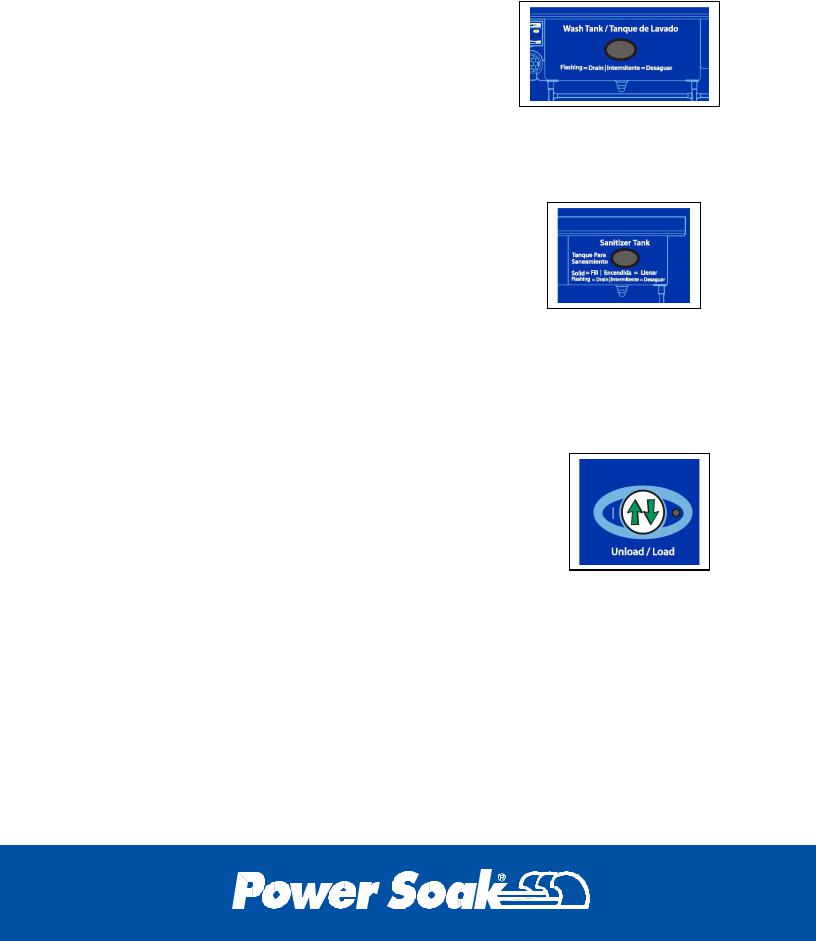
5.4 Blue Wash Tank Light
Solid Illumination – “CHANGE WASH SOLUTION” the wash cycle will be stopped until the wash tank is completely drained and refilled.
Slow to Fast Flashing – wash solution life has expired, 15 minute warning prior to solid illumination.
Flashing with Green Status light – occurs when tank is filling with water indicating near full, rapid flashing indicates that the tank is full (NOTE: the fill indication feature is an option that must be selected in the UPM settings.)
5.5 Red Sanitizer Tank Light
Solid Illumination – “FILL SANITIZER TANK” – sanitizer tank must be filled to the waterline.
OR
Solid Illumination – “CHANGE SANITIZE SOLUTION” – After two hours, the sanitizer tank must be drained and refilled.
Slow to Fast Flashing – wash solution life has expired, 15 minute warning prior to solid illumination.
Flashing with Green Status light – occurs when tank is filling with water indicating near full, rapid flashing indicates that the tank is (NOTE: the fill indication feature is an option that must be selected in the UPM settings.)
5.6 Green Unload/Load Light
Flashing – wash cycle is complete, time to unload the items from the wash tank (press the Load/Unload button to start the unload timer).
Solid – unload timer is operating (press the Load/Unload when the unloading is complete).
(NOTE: Proper operation of the Load/Unload button according to the flashing of the green light along with keeping the wash tank continuously operating will extend the wash solution life).
10

5.7 Error Codes
Certain conditions create errors in the program operation. The green “Status” light on the front of the control panel along with the error code light on the UPM will blink in patterns to indicate the source of the error. The definitions for the patterns are as follows:
“_“ symbol represents a “long” flash “.” symbol represents a “short” flash
3 long & 1 short |
_ _ _ . = Liquid Level Error |
3 long & 2 short |
_ _ _ . . = Temperature Sensor Error |
3 long & 3 short |
_ _ _ . . . = Over-Current Error |
3 long & 4 short |
_ _ _ . . . . = Over Temperature Error |
3 long & 5 short |
_ _ _ . . . . . = Current Sensor Error |
3 long & 6 short |
_ _ _ . . . . . . = Membrane Error |
Liquid Level Error – This error appears when the upper liquid level sensor sends a signal to the UPM (W-H light is illuminated) and the low liquid level sensor is not sending a signal to the UPM (W-L is not illuminated). The low level sensor may not be functioning due to a coating of debris or a broken/disconnected wire that is preventing the signal to the UPM. A continuous signal from the upper level sensor can be caused by debris coating the face of the sensor or faulty wiring that has the sensor connection grounded to the wash tank when there is no fluid in the tank. The liquid level lights on the UPM can be used to help determine the problem (see Section 6.0 UPM & Section 7.6 Liquid Level Sensor).
Temperature Sensor Error – When the UPM receives a signal from the thermistor (see Section 7.5 Thermistor) that is outside the range of the UPM programming, the temperature sensor error will actuate.
Over Current Error – If any of the high voltage components begin drawing excessive current, the current sensor will send a signal to the UPM to start the Over Current Error and deactivate the contactor which turns the power off to the machine (see Section 6.6 Contactor & Section 6.7 Load Sensor).
Over Temperature Error – If the fluid temperature in the wash tank exceeds 135°F it will activate this error message and stop the machine. This error code cannot be reset until the fluid is drained below the low level sensor in the wash tank.
Current Sensor Error – The UPM must receive a signal from the current sensor to verify that it is connected and working. If it does not receive the signal, the UPM program will stop the machine and give this error code (see Section 6.7 Load Sensor).
11

Membrane Error – In the event that one of the control panel buttons sends a constant signal to the UPM, the program will recognize that the membrane is defective and display this error code (see Section 6.9 Push Button Membrane).
Note: There are periods of unstable power from the incoming power source that can cause a false error. Turning the electrical power off and on can reset the program if it is a power source fluctuation that caused the error. Locate the wall mounted circuit breaker box, turn the circuit breaker for the Power Soak machine off, pause for 15 seconds, turn the circuit breaker back on, and then check to see if the error code has cleared.
The error codes will have to be reset by a procedure that can be explained by the Power Soak Service department (1-800-444-9624). Please have the “Error Code” information available when calling Power Soak Systems for telephone assistance. The machine serial number will also be helpful to identify the configuration of the machine. The serial number is 5-6 digits long and located on the identification tag which is on the lower corner of the wash tank close to the control panel enclosure.
12
 Loading...