

Page 1
Technical Instructions
!
WARNING
Read this Manual BEFORE using this equipment.
Failure to read and follow all safety and use infor-
mation can result in death, serious personal injury,
property damage, or damage to the equipment.
Keep this Manual for future reference.
!
WARNING
FAILURE TO COMPLY WITH PROPER INSTALLATION AND
MAINTENANCE INSTRUCTIONS COULD CONTRIBUTE TO THE
VALVE FAILURE.
This Hot Water Master Tempering Valves cannot be used for
tempering water temperature at fixtures. Severe bodily injury
(i.e., scalding or chilling) and/or death may result depending
upon system water pressure changes and/or supply water
temperature changes. ASSE standard 1016, 1069 or 1070 listed
devices should be used at fixtures to prevent possible injury.
These Hot Water Tempering Valves are designed to be
installed at or near the boiler or water heater. They are not
designed to compensate for system pressure fluctuations and
should not be used where ASSE standard 1016, 1069 or 1070
devices are required. These valves should never be used to
provide “anti-scald” or “anti-chill” service.
The components of the system must be of materials with a
construction capable of withstanding the high limit output temperatures of the water heating source.
!
WARNING
Need for Periodic Inspection and Yearly Maintenance:
Periodic inspection and yearly maintenance by a licensed contractor is required. Corrosive water conditions and/or unauthorized adjustments or repair could render the valve ineffective for
service intended. Regular checking and cleaning of the valve’s
internal components and check stops helps assure maximum
life and proper product function. Frequency of cleaning and
inspection depends upon local water conditions.
!
WARNING
You are required to consult the local building and plumbing
codes prior to installation. If the information in this manual is
not consistent with local building or plumbing codes, the local
codes should be followed. Inquire with governing authorities for
additional local requirements.
IS-P-SF-MM430-2V-HiLo
HydroGuard
®
XP Series LFMM430 2 Valve
Hi/Lo Supply Fixture
Advanced Thermal Activation
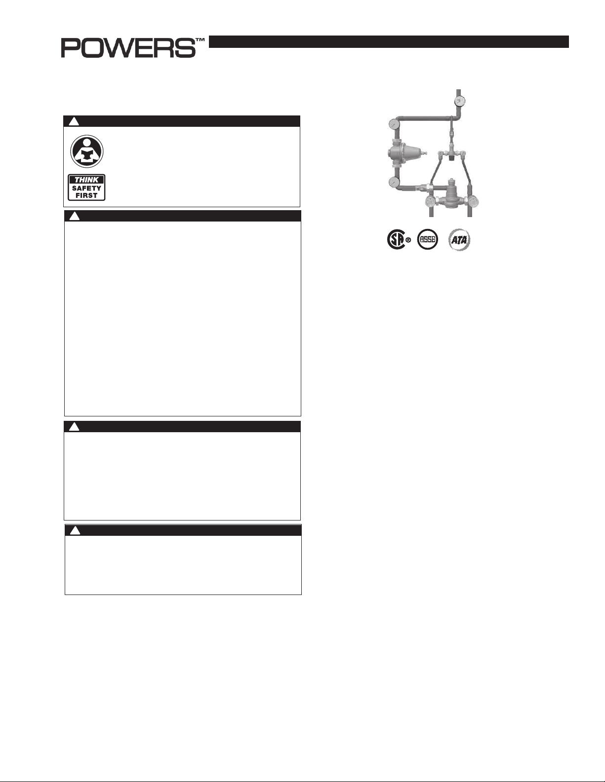
Description n
Powers' HydroGuard® XP Series LFMM430 Hi/Lo's are fully assembled factory tested systems, designed to provide safe water throughout commercial and institutional facilities. HydroGuard
LFMM430 Hi/Lo systems consist of Series LFLM490 and Series
LFMM430 thermostatic valves which utilize paraffin-based actuation
technology to sense and adjust outlet temperature. Each system
also includes a PRV, ball valves, pressure/temperature gauges and
Powers' triple-duty checkstops. Optional equipment includes cabinets.
Description n
Two-valve supply fixtures feature a low capacity valve that works
in parallel with a high capacity valve. During low demand, the
low capacity valve handles the load requirements. As the load
demand is increased, the pressure reducing valve, which is set at
a certain pressure differential, will open and allow flow through the
high capacity valve to assist the low capacity valve in meeting the
increased load requirements.
Specifications n
Maximum Operating Pressure .................. 125psi (861 kPa)
Maximum Hot Water Temperature ........... 200°F (93°C)
Minimum Hot Water Supply Temp*............. 5°F (3°C) Above Set-Point
Hot Water Inlet Temperature Range ........ 120 -180°F (49 - 82°C)
Cold Water Inlet Temperature Range ....... 40 - 80°F (4 - 27°C)
Minimum Flow**............................................ 0.5 gpm (1.89 lpm)
®
XP Series
Temp. Adjustment Range *** ..................... 90 - 160°F (32 - 71°C)
Listing/Compliance (Valve Only) ................ ASSE 1017, CSA B125
* With Equal Pressure
** Minimum flow when HiLo is installed at or near hot water source recirculating
tempered water with a properly sized continuously operating recirculating pump.
*** Note: Low limit cannot be less than the cold water temperature. For best
operation, hot water should be at least 5°F (3°C) above desired set point.
Page 2
Capacity n
Model
LFMM431HL
LFMM432HL
LFMM433HL
LFMM434HL
LFMM435HL
Prior to Installation n
Flow Capacity at 50-50 Mixed Ratio
Pressure Drop Across Valve
Min. Flow
to ASSE 1017
0.5 gpm
1.89 lpm 83 lpm 117 lpm 163 lpm 201 lpm 246 lpm 284 lpm
0.5 gpm
1.89 lpm 110 lpm 155 lpm 220 lpm 250 lpm 329 lpm 352 lpm
0.5 gpm
1.89 lpm 167 lpm 238 lpm 326 lpm 409 lpm 503 lpm 579 lpm
0.5 gpm
1.89 lpm 212 lpm 299 lpm 420 lpm 515 lpm 632 lpm 731 lpm
3.0 gpm
11.0 lpm 235 lpm 333 lpm 469 lpm 575 lpm 704 lpm 814 lpm
C
9.7
13.0
19.8
24.9
27.7
V
5psi 10psi 20psi 30psi 45psi 60psi
(34 kPa) (69 kPa) (138 kPa) (207 kPa) (310 kPa) (414 kPa)
22 gpm 31 gpm 43 gpm 53 gpm 65 gpm 75 gpm
29 gpm 41 gpm 58 gpm 66 gpm 87 gpm 93 gpm
44 gpm 63 gpm 86 gpm 108 gpm 133 gpm 153 gpm
56 gpm 79 gpm 111 gpm 136 gpm 167 gpm 193 gpm
62 gpm 88 gpm 124 gpm 152 gpm 186 gpm 215 gpm
1. Flush all piping thoroughly before installing.
2. Make sure all ball valve handles are in "OFF" position.
3. In order to make any temperature adjustment to the valves,
you must open end-of-line fixtures to ensure you have adequate flow across the valve.
Set Up Procedure n
You must follow these procedures in order to properly adjust your Hi/
Lo System. You need flow greater than the minimum shown in capacity table across the valve in order to set a maximum temperature.
1. Close the low flow valve on the outlet of the low flow valve.
2. Open the ball valve at the discharge of the high flow valve.
3. Open enough fixtures to meet the minimum flow requirement as
per capacity table.
4. Set valve temperature. Refer to IS-P-LFMM430.
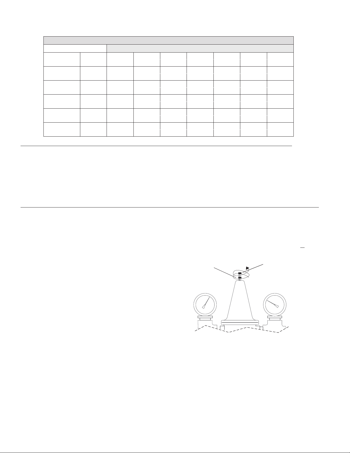
5. Set the PRV as follows for a 15psi differential.
a) Loosen the locknut at the top of the PRV. This must be all the
way out or you will be limiting the range of the adjustment. b)
Adjust the PRV so the outlet pressure gauge (top) reads 15psi
less than the supply pressure gauge (bottom). Turning the
adjustment screw counterclockwise will increase the differential
across the PRV (allowing the PRV to open later).
6. Close the ball valve at the discharge of the high flow valve and
open the low flow side ball valve by rotating the handle fully
counterclockwise.
7. Open enough fixtures to meet the minimum flow requirement as
per capacity table.
8. Set the temperature for the low flow valve. Refer to
IS-P-LFLM490-LFLM490-10.
9. Open the ball valve at the discharge of high flow valve.
10. Open additional fixtures to create a 20psi differential between
supply and outlet pressure gauges.
11. When water is at desired outlet temperature, verify temperature
remains at set point.
4. Use a thermometer at the showerhead or install an in-line
thermometer at the point-of-use.
Adjustment Screw
CW: Increases outlet pressure and
Lock Nut
Turn fully CCW
(counterclockwise)
before setting PRV.
Supply Pressure Gauge Outlet Pressure Gauge
decreases differential across PRV or
CCW: Decreases outlet pressure and
increases differential across PRV.
12. Gradually start to close fixtures to verify that the temperature
remains constant through the full range of flow.
13. For any problem, refer to Troubleshooting section of the docu-
ment or contact Powers' Technical Support Department at
1.800.669.5430 or info@powerscontrols.com.
2
Page 3

Adjusting to Individual High Flow and Low Flow Valves n
See enclosed IS-P-LFLM490-LFLM490-10 and IS-P-LFMM430.
Troubleshooting n
What to look for if:
• Outlet temperature is too hot with low ow:
1. The maximum temperature of the low flow valve was not properly set. Refer to set up procedure and reset the maximum
temperature of the low flow valve.
2. The thermal actuator of the low flow valve is not working properly. Replace accordingly to the appropriate technical instructions (IS-P-LFLM490-LFLM490-10 and IS-P-LFMM430).
• Outlet temperature is too hot with a high ow:
1. The maximum temperature of a high flow valve was not properly set. Refer to Set Up Procedure and reset the maximum
temperature of the high flow valve.
2. The thermal actuator of the high flow valve is not working properly. Replace accordingly, IS-P-LFMM430 enclosed.
• Outlet temperature too low on low and high ow:
1. The hot water temperature is too low. You must have a supply
temperature of at least 5°F (3°C) higher than the set temperature. Re-adjust the hot water supply.
2. The checkstops on the hot side of the valve are not fully open,
or may be stuck due to liming. Open and clean checkstops.
3. The temperature has not been set properly on the small and/or
large valve. Refer to Set Up Procedure and reset the valves.
• Outlet ow drops off:
1. The differential across the PRV is set too high, so the high flow
valve begins controlling the system too late, and starves the
system. Refer to the Set Up Procedure and decrease the differential across PRV.
2. The checkstops on the high flow valves are not fully open or are
stuck due to liming. Open and clean checkstops.
3. The system pressure varies by more than 50% of the inlet supply pressure.
• Outlet temperature cycles between hot and cold:
1. The differential across the PRV is set too low, so the high flow
valve begins controlling the system too early and therefore,
cycles (hunt for the set point). Refer to the Set Up Procedure
and increase the differential across PRV.
2. The system pressure varies by more than 50% of the inlet supply pressure.
Preventative Maintenance n
Thermostatic water mixing valves are control devices which must
be cleaned and maintained on a regular basis.
1. Before servicing checkstops or piping, turn off the water
upstream. At least every twelve (12) months, open up the checkstops and check for the free movement of the poppet.
2. Before servicing the valve, turn off the water supply upstream
or close the checkstops. To close the checkstops, turn the
adjusting screw clockwise.
3. When opening checkstops after servicing, turn adjusting screw
counterclockwise to fully open position then turn adjusting
screw 1/2 turn clockwise for final setting.
4. Every three (3) months, check the maximum temperature adjustments.
5. Every twelve (12) months, remove the valve bonnets and check
the internal components for freedom of movement.
Parts Kits n
See enclosed IS-P-LFLM490_LFLM490-10 and IS-P-LFMM430.
!
WARNING
Any changes in supply condition could effect the outlet water temperature. Check and adjust the valves
accordingly to prevent injury to the users. After completing repairs, check discharge temperature, (105°F
[41°C]). Reset if necessary. Failure to perform this
operation could result in unsafe discharge temperature, which may cause injury or death.
3
Page 4

WARNING: This product contains chemicals known to the
State of California to cause cancer and birth defects or
other reproductive harm.
For more information: www.watts.com/prop65
Warranty n
The Seller warrants that the equipment manufactured by it and covered by this order or contract is free from defects in material and workmanship and, without charge, equipment found to be defective in material or workmanship will be repaired, or at Seller’s option replaced F.O.B. original point of shipment, if
written notice of failure is received by Seller within one (1) year after date of shipment (unless specifically noted elsewhere), provided said equipment has
been properly installed, operated in accordance with the Seller’s instructions, and provided such defects are not due to abuse or decomposition by chemical
or galvanic action. THIS EXPRESS WARRANTY IS IN LIEU OF AND EXCLUDES ALL OTHER WARRANTIES, GUARANTEES, OR REPRESENTATIONS, EXPRESS
OF IMPLIED. THERE ARE NO IMPLIED WARRANTIES OF MERCHANTABILITY OR OF FITNESS FOR A PARTICULAR PURPOSE. The Seller assumes no responsibility for repairs made on the Seller’s equipment unless done by the Seller’s authorized personnel, or by written authority from the Seller. The Seller makes no
guarantee with respect to material not manufactured by it.
A Watts Water Technologies Company
USA: Phone: 1.800.669.5430 • Fax 1.847. 229.0526 • www.powerscontrols.com
Canada: Phone: 1.888.208.8927 • Fax 1.888. 479.2887 • www.powerscontrols.ca
IS-P-SF-MM430-2V-HiLo 1336 EDP# 6512307 © 2013 Powers
 Loading...