

Page 1
HYDROGUARD
ASSE 1017 Series LFLM490 and LFLM490-10
Installation Instructions
!
WARNING
Read this Manual BEFORE using this equipment.
Failure to read and follow all safety and use infor-
mation can result in death, serious personal injury,
property damage, or damage to the equipment.
Keep this Manual for future reference.
!
WARNING
You are required to consult the local building and plumbing
codes prior to installation. If the information in this manual
is not consistent with local building or plumbing codes,
the local codes should be followed. Inquire with governing
authorities for additional local requirements.
!
WARNING
FAILURE TO COMPLY WITH PROPER INSTALLATION AND
MAINTENANCE INSTRUCTIONS COULD CONTRIBUTE TO THE
VALVE FAILURE.
This Hot Water Master Tempering Valves cannot be used for
tempering water temperature at fixtures. Severe bodily injury
(i.e., scalding or chilling) and/or death may result depending
upon system water pressure changes and/or supply water
temperature changes. ASSE standard 1016, 1069 or 1070 listed
devices should be used at fixtures to prevent possible injury.
These Hot Water Tempering Valves are designed to be
installed at or near the boiler or water heater. They are not
designed to compensate for system pressure fluctuations and
should not be used where ASSE standard 1016, 1069 or 1070
devices are required. These valves should never be used to
provide “anti-scald” or “anti-chill” service.
The components of the system must be of materials with a
construction capable of withstanding the high limit output temperatures of the water heating source.
IS-P-LM490-LM490-10
®
Thermostatic Tempering Valves
LFLM490-1
Advanced Thermal
Activation
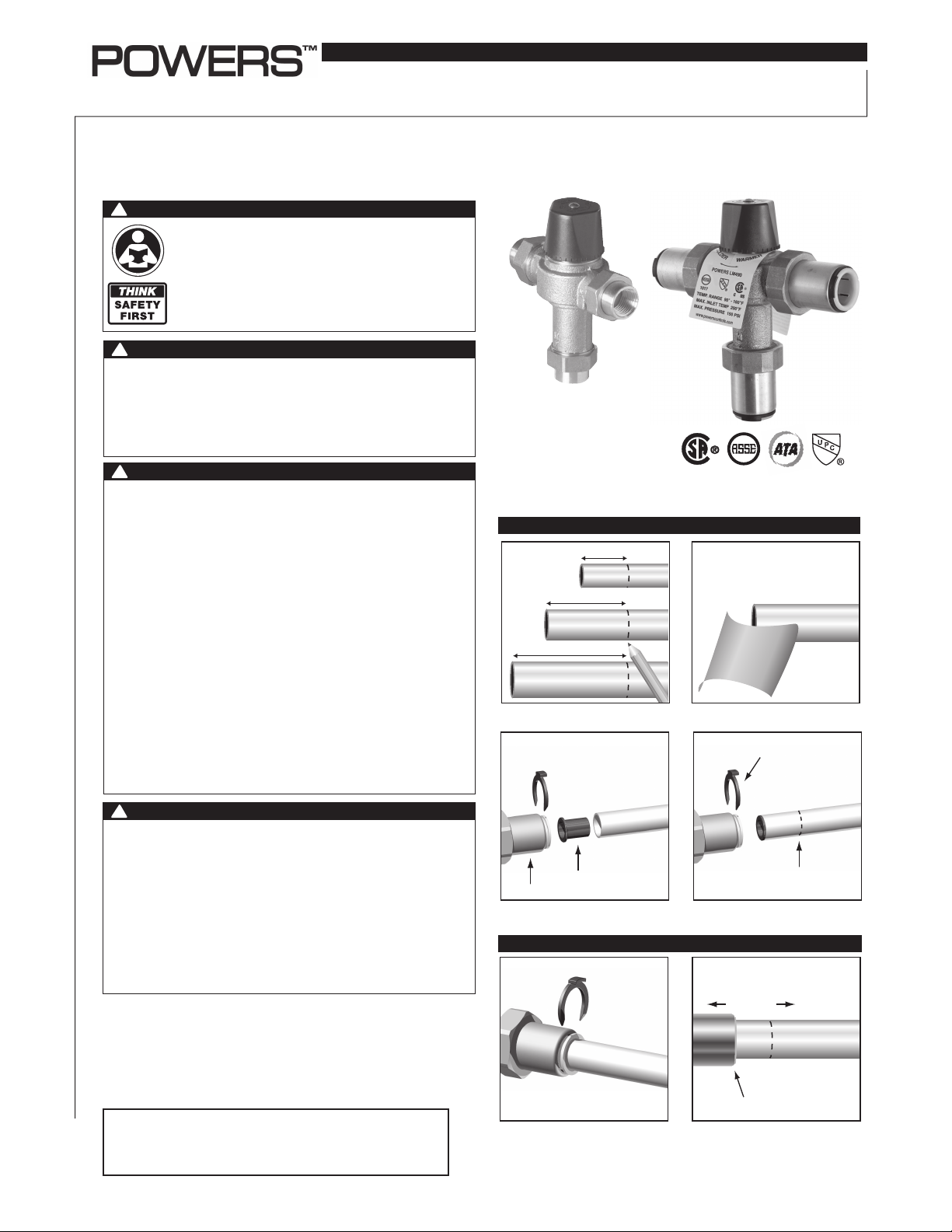
Quick-Connect Installation n
TO CONNECT
1
1
/2 in. (38.1mm)
1
/2 in.Pipe (12.7mm)
3
/4 in. (44.45mm)
1
3
/4 in.Pipe (19.05mm)
7
1
/8 in. (47.63mm)
1 in.Pipe (25.4mm)
1. Mark pipe as shown.
This is pipe insertion depth.
PEX tubing only
2. Clean pipe end.
Collet clip
LFLM490-5
!
WARNING
Need for Periodic Inspection and Yearly Maintenance:
Periodic inspection and yearly maintenance by a licensed
contractor is required. Corrosive water conditions, and/or
unauthorized adjustments or repair could render the valve
ineffective for service intended. Regular checking and
cleaning of the valve’s internal components and check
stops helps assure maximum life and proper product
function. Frequency of cleaning and inspection depends
upon local water conditions.
ATTENTION INSTALLER:
After installation, please leave this Instruction Sheet
for occupant’s information.
Tail Piece
3. If using PEX tubing, insert pipe stiffener (provided) into end of pipe.
Pipe Stiffener
4. Push tubing into tailpiece up to mark.
5. Insert collet clip.
TO DISCONNECT
Collet depressed
1. Remove collet clip. 2. Depress collet.
3. Pull tubing from tailpiece .
Mark
Page 2
Installation Instructions n
WARNING
!
Flush all pipes thoroughly before installation. Installation and
field adjustment are the responsibility of the installer.
1. Close both hot and cold water shutoff valves upstream of the
tempering valve.
2. Bleed pressure from the system.
3. Route copper tubing or piping to fit valve dimensions.
4. For valves with Quick-Connect tailpieces refer to "Quick-
Connect Installation" instructions.
5. Remove tailpieces from the valve and make sure union nuts
are over the tubing/piping before connecting to the tailpiece.
NOTICE
If soldering, remove unions and gaskets from valve body prior to
soldering to prevent damage to valve from excessive heat.
6. Flush piping again, install valve using filter gasket on hot and
cold water inlets and fiber gasket on mixed water outlet.
7. Turn on the cold and hot water. If a leak is observed, tighten
connections as necessary to stop leak before proceeding.
V acuum Relief V alve
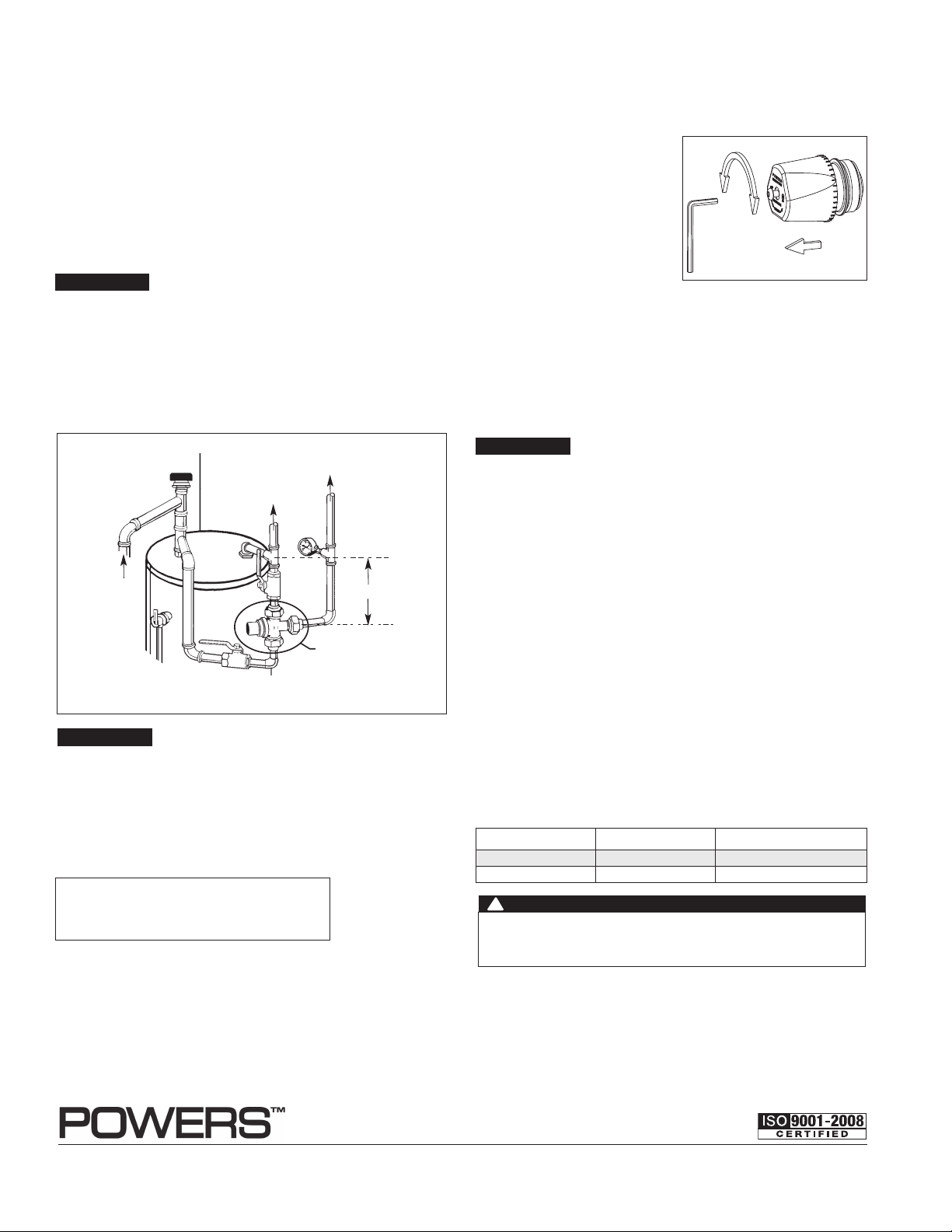
To Adjust Temperature (Figure 2) n
LFLM490 is factory pre-set to 120°F (49°C) and LFLM490-10 is
factory set to 90°F (31°C) outlet temperatures under the following
conditions:
Cold inlet: 60° - 70°F (16 - 21°C)
Turn
Hot inlet: 140° - 145°F (60 63°C) Supply Pressures: 45psi
Hotter
(310 kPa)
1. Let the water flow for at least
two minutes to allow supply
temperature to stabilize.
2. Place a thermometer in the
outlet water stream.
3. Loosen handle screw with hex
Colder
Hex Wrench
Unscrew, Lift Cap
to Adjust
Temperature Adjustment
Figure 2.
wrench.
4. Handle must be lifted 1/4" to adjust temperature. Rotate
handle clockwise to decrease temperature and counterclockwise to increase the temperature.
5. Lower handle and tighten screw.
6. Check for outlet temperature.
NOTICE
Pressure differential between hot & cold water supplies must be
less then 25%.
T&P
Relief Valve
Hot to Appliances
Cold
Cold
Cold
Temperature Gauge
Hot
H
M
C
LFLM490, LFLM490-10
T emper ed
8" - 10"
Figure 1. Domestic Hot Water Application
NOTICE
To prolong the life of the series LFLM490 or LFLM490-10 valves,
it is recommended that the hot water inlet to the valve should be
8-10”(200-305mm) below the hot water inlets.
WARNING: This product contains chemicals known to the
State of California to cause cancer and birth defects or
other reproductive harm.
For more information: www.watts.com/prop65
Warranty n
Troubleshooting n
Fluctuating or erratic hot water temperature at fixture:
Unbalanced Pressure. Install balancing or throttling valve at the
hot and cold water supplies and adjust accordingly for demand.
Hot water backing up into cold water line:
Hot water pressure is higher than cold water pressure.
Examine check valves for dirt & debris, clean as necessary.
Cannot adjust water temperature to desired temperature:
Install balancing or throttling valve at the hot and cold water
supplies and adjust accordingly for demand.
High pressure drop through the tempering valve:
Valve undersized. Install larger thermostatic tempering valve.
Insufficient hot water during peak demand:
Check flow requirement during peak demand period. Use larger
thermostatic tempering valve.
Repair Kit n
Model Part # Description
LFLM490 490-090 Plunger/Motor Assembly
LFLM490-10 490-190 Plunger/Motor Assembly
For valves with CPVC or PEX end connections, do not exceed the
tubing manufacturers pressure and temperature ratings. Refer to the
tubing manufacturers product specications for that information.
The Seller warrants that the equipment manufactured by it and covered by this order or contract is free from defects in material and workmanship and, without
charge, equipment found to be defective in material or workmanship will be repaired, or at Seller’s option replaced F.O.B. original point of shipment, if written
notice of failure is received by Seller within one (1) year after date of shipment (unless specifically noted elsewhere), provided said equipment has been properly
installed, operated in accordance with the Seller’s instructions, and provided such defects are not due to abuse or decomposition by chemical or galvanic action.
THIS EXPRESS WARRANTY IS IN LIEU OF AND EXCLUDES ALL OTHER WARRANTIES, GUARANTEES, OR REPRESENTATIONS, EXPRESS OF IMPLIED. THERE ARE
NO IMPLIED WARRANTIES OF MERCHANTABILITY OR OF FITNESS FOR A PARTICULAR PURPOSE. The Seller assumes no responsibility for repairs made on the
Seller’s equipment unless done by the Seller’s authorized personnel, or by written authority from the Seller. The Seller makes no guarantee with respect to material
not manufactured by it.
A Watts Water Technologies Company
IS-P-LM490-LM490-10 1336 EDP# 6511207 © 2013 Powers
USA: Tel: (800) 669-5430 • Fax: (847) 229-0526 • www.powerscontrols.com
Canada: Tel: (888) 208-8927 • Fax: (888) 479-2887 • www.powerscontrols.ca
 Loading...