

Page 1

POW8561 EN
1 APPLICATION ................................................................................... 3
2 DESCRIPTION (FIG. A) ..................................................................... 3
3 PACKAGE CONTENT LIST .............................................................. 3
4 SYMBOLS .......................................................................................... 4
5 GENERAL POWER TOOL SAFETY WARNINGS ............................ 4
5.1 Working area ............................................................................................................. 4
5.2 Electrical safety ......................................................................................................... 4
5.3 Personal safety ......................................................................................................... 5
5.4 Power tool use and care ........................................................................................... 5
5.5 Service ....................................................................................................................... 6
6 SAFETY EQUIPMENT ....................................................................... 6
6.1 Cleaving wedge (Fig. 1) ............................................................................................ 6
6.2 Saw blade protector .................................................................................................. 6
6.3 Push stick (Fig. 2) ..................................................................................................... 6
7 UNPACKING AND ASSEMBLY ........................................................ 6
7.1 Assembly ................................................................................................................... 6
7.2 Fitting the parallel fence (Fig. 4) ............................................................................... 7
7.3 Mounting mitre angle stop (Fig. 5) ........................................................................... 7
7.4 Mounting the saw blade protector ........................................................................... 7
7.5 Mounting the extraction ............................................................................................ 8
8 OPERATION ...................................................................................... 8
8.1 Check before starting the device! ............................................................................ 8
8.2 Operating elements ................................................................................................... 8
8.2.1 On/off switch ............................................................................................................... 8
8.2.2 Overload Protection (15) ............................................................................................. 8
8.2.3 Setting mechanism for the tilt angle ............................................................................. 8
8.2.4 Hand crank for setting the cutting height ..................................................................... 8
8.3 Workpiece stops ....................................................................................................... 9
8.3.1 Mitre angle stop .......................................................................................................... 9
8.3.2 Mitre cuts (Fig. 6) ........................................................................................................ 9
8.3.3 Setting the stop rail of the parallel stop ........................................................................ 9
Copyright © 2014 VARO P a g e | 1 www.varo.com
Page 2

POW8561 EN
8.3.4 Parallel stop ................................................................................................................ 9
8.4 Setting the cutting height (Fig. 7) ............................................................................. 9
8.5 Setting the saw blade angle (Fig. 7) ....................................................................... 10
8.6 Sawing ..................................................................................................................... 10
9 CLEANING AND MAINTENANCE .................................................. 11
9.1 Cleaning and maintenance overview ..................................................................... 11
9.2 Cleaning the device ................................................................................................ 11
9.3 Unit maintenance .................................................................................................... 11
9.3.1 Fitting and changing the saw blade ........................................................................... 12
9.3.2 Adjusting the cleaving wedge .................................................................................... 12
10 STORAGE, TRANSPORTATION .................................................... 12
10.1 Storage .................................................................................................................... 12
10.2 Transportation ......................................................................................................... 12
11 TECHNICAL DATA .......................................................................... 13
12 NOISE ............................................................................................... 13
13 WARRANTY ..................................................................................... 13
14 ENVIRONMENT ............................................................................... 14
15 DECLARATION OF CONFORMITY ................................................ 15
Copyright © 2014 VARO P a g e | 2 www.varo.com
Page 3

POW8561 EN
TABLE SAW 1800W
POW8561
1 APPLICATION
The device is designed to cleave and-cross-cut solid wood, laminated wood, chipboard, wood
core plywood and similar wooden materials. Round pieces may not be sawed as the rotating
saw blade may cause them to roll. Only those materials may be processed for which the
particular saw blade is designed. Only saw blades suitable for the unit (carbide and chrome
vanadium blades) may be used. The use of high-speed steel blades and cutting wheels of any
type is not permitted. The unit may not be used in areas where there is an explosion hazard.
The unit is not designed for commercial, trade or industrial use.
WARNING! For your own safety, read this manual and the general safety
instructions carefully before using the appliance. Your power tool should
only be given to other users together with these instructions.
2 DESCRIPTION (FIG. A)
1. On switch I (green) / Off switch 0
(red)
2. Locking for saw blade angle
adjustment
3. Saw blade angle adjustment (rotary
knob)
4. Saw blade height adjustment (crank)
5. Parallel stop
6. Saw blade protector with extraction
struts
7. Cleaving wedge
8. Table extension
9. Mitre angle stop
10. Scale (cm/mm)
11. Extraction hose
12. Base frame
13. Connection for dust extraction
14. Cut angle indicator
15. Overload protection
16. Push stick
17. Bracket
18. Adapter
19. Allen wrench
20. Flange key
21. Locking lever for parallel stop
3 PACKAGE CONTENT LIST
Remove all packaging.
Remove remaining packing and packing inserts (if included).
Check that the package contents are complete.
Check the appliance, the power cord, the power plug and all accessories for transportation
damage.
Keep the packaging until expiration of the warranty period. Then take it to your local waste
disposal system.
WARNING: Packaging materials are not toys! Children must not play with
plastic bags! There is a danger of suffocation!
Bench circular saw with
saw blade
Blade guard
Saw bench
2 saw bench extenders
If any parts are missing or damaged, please contact your dealer.
Copyright © 2014 VARO P a g e | 3 www.varo.com
4 brackets
Parallel fence
Angle fence
Push-stick
2 spanners for blade
change
Fastening material (such
as screw, nut and so on)
Operating Instructions
Page 4
POW8561 EN
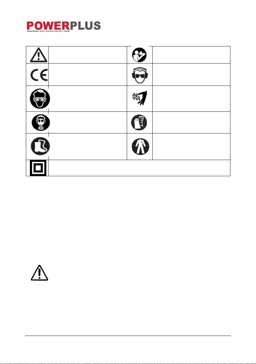
Denotes risk of personal injury or
damage to the tool.
Read manual before use.
Conforms to essential safety
standards of applicable
European directives.
Wear ear guards and goggles.
Wear eye protection.
Keep hands away from blades,
Don’t touch the blades when
starting or while operating the
unit.
Wear a mask In dusty
conditions!
Wear gloves!
Wearing of protective shoes
advised!
Wear good, hardy work clothes!
Class II - The machine is double insulated; Earthing wire is therefore not
necessary.
4 SYMBOLS
The following symbols are used in this manual and/or on the machine:
5 GENERAL POWER TOOL SAFETY WARNINGS
Read all safety warnings and instructions. Failure to heed warnings and follow instructions
may result in electric shock, fire and/or serious injury. Keep safety warnings and instructions
for future reference. The term "power tool" in the safety warnings refers to your mainsoperated (corded) power tool or battery-operated (cordless) power tool.
5.1 Working area
Keep working area clean and well lit. Untidy and dark areas can lead to accidents.
Do not operate power tools in potentially explosive surroundings, for example, in the
presence of inflammable liquids, gases or dust. Power tools create sparks that may ignite
the dust or fumes.
Keep children and bystanders at a distance when operating a power tool. Distractions can
cause you to lose control of it.
5.2 Electrical safety
Always check that the power supply corresponds to the voltage on the
rating plate.
Power tool plugs must match the outlet. Never modify the plug in any way. Do not use
adapter plugs with earthed power tools. Unmodified plugs and matching outlets will reduce
the risk of a lethal electric shock.
Avoid body contact with earthed surfaces such as pipes, radiators, kitchen ranges and
refrigerators. There is an increased risk of a lethal electric shock if your body is earthed.
Do not expose power tools to rain or wet conditions. If water gets inside a power tool, it will
increase the risk of a lethal electric shock.
Copyright © 2014 VARO P a g e | 4 www.varo.com
Page 5

POW8561 EN
Do not damage the cord. Never use the cord for carrying, pulling or unplugging the power
tool. Keep the cord away from heat, oil, sharp edges or moving parts. Damaged or tangled
cords increase the risk of a lethal electric shock.
When operating a power tool outdoors, use an extension cable suitable for outdoor use.
Using a cord suitable for outdoor use reduces the risk of a lethal electric shock.
If operating a power tool in a damp location is unavoidable, use a power supply protected
by a residual current device (RCD). Using an RCD reduces the risk of a lethal electric
shock.
5.3 Personal safety
Stay alert, watch what you are doing and use common sense when operating a power
tool. Do not use a power tool when you are tired or under the influence of drugs, alcohol or
medication. A moment of inattention when operating a power tool may result in serious
personal injury.
Use safety equipment. Always wear eye protection. Using safety equipment such as a
dust mask, non-skid safety shoes, a hard hat, or hearing protection whenever it is needed
will reduce the risk of personal injury.
Avoid accidental starts. Ensure the switch is in the off position before inserting the plug.
Carrying power tools with your finger on the switch or plugging in power tools when the
switch is in the on position makes accidents more likely.
Remove any adjusting keys or spanners before turning on the power tool. A spanner or
key left attached to a rotating part of the power tool may result in personal injury.
Do not reach out too far. Keep your feet firmly on the ground at all times. This will enable
you to retain control over the power tool in unexpected situations.
Dress properly. Do not wear loose clothing or jewellery. Keep your hair, clothing and
gloves away from the power tool. Loose clothes, jewellery or long hair can become
entangled in the moving parts.
If there are devices for connecting dust extraction and collection facilities, please ensure
that they are attached and used correctly. Using such devices can reduce dust-related
hazards.
5.4 Power tool use and care
Do not expect the power tool to do more than it was designed to do. Use the correct power
tool for what you want to do. A power tool will achieve better results and be safer if used in
the circumstances for which it was designed.
Do not use the power tool if the switch cannot turn it on and off. A power tool with a broken
switch is dangerous and must be repaired.
Disconnect the plug from the power source before making adjustments, changing
accessories, or storing power tools. Such preventive safety measures reduce the risk of
starting the power tool accidentally.
Store power tools when not in use, out of the reach of children and do not allow people
who are not familiar with the power tool or these instructions to operate it. Power tools are
potentially dangerous in the hands of untrained users.
Maintenance. Check for misalignment or jammed moving parts, breakages or any other
feature that might affect the operation of the power tool. If it is damaged, the power tool
must be repaired. Many accidents are caused by using poorly maintained power tools.
Keep cutting tools sharp and clean. Properly maintained cutting tools with sharp cutting
edges are less likely to jam and are easier to control.
Use the power tool, accessories and cutting tools, etc., in accordance with these
instructions and in the manner intended for the particular type of power tool, taking into
account the working conditions and the work which needs to be done. Using a power tool
in ways for which it was not intended can lead to potentially hazardous situations.
Copyright © 2014 VARO P a g e | 5 www.varo.com
Page 6

POW8561 EN
Connect the four table legs (1) with the four
cross braces (2). For this, fix each cross brace
from the inside with two screws (3) (incl.
washers) and counternuts (4) to each table leg.
1
3
4
2
5.5 Service
Your power tool should be serviced by a qualified specialist using only standard spare
parts. This will ensure that it meets the required safety standards.
6 SAFETY EQUIPMENT
6.1 Cleaving wedge (Fig. 1)
The cleaving wedge (7) prevents a workpiece being caught by the ascending teeth and being
thrown against the operator. The cleaving wedge must remain in place during operation.
6.2 Saw blade protector
The saw blade protector (6) protects the user from accidentally touching the saw blade and
from flying splinters. The saw blade protector must always remain in place during operation.
6.3 Push stick (Fig. 2)
The push stick (16) serves as an extension of the hand and protects the user from accidentally
touching the saw blade. The push stick must always be used when the gap between the stop
and the saw blade is less than 120 mm.
7 UNPACKING AND ASSEMBLY
Unpack the unit and make sure all of the pieces are there.
Note: If any of the parts is missing or damaged contact the retailer.
7.1 Assembly
Mount base frame (12) and table enlargements and extensions
The base frame (12) consists of four table legs with cross braces that must be mounted.
Required tools:
2 combination wrenches
Allen wrench
The brackets (17) are fitted through the screw holes in the housing. (Fig. 3)
Note: Only place the device on a level, skid-proof surface. The device must
not wobble.
Copyright © 2014 VARO P a g e | 6 www.varo.com
Page 7

POW8561 EN
Lower the saw blade with the hand crank for height
adjustment (4) so that the drill hole (A) in the
cleaving wedge (7) is still accessible.
Loosen wing nuts on the saw blade protector (6)
and remove together with the bolt screw and
washer.
Position the saw blade protector (6) with the
groove on the cleaving wedge and align the hole of
the saw blade protector with the hole of the
cleaving wedge.
Fit the bolt screw through the hole and fix with
washer and wing nut.
7.2 Fitting the parallel fence (Fig. 4)
Insert the parallel fence (5) into the rail of the measuring scale. Check the setting at the
window. Turn the knob to lock the parallel fence (5) into place. In order to obtain a perfectly
parallel cut, you should check the gap between the fence and the saw blade at two positions
using a meter rule.
7.3 Mounting mitre angle stop (Fig. 5)
The mitre angle stop (9) consists of two parts - the stop plate (A) and the angle adjustment (B)
that must be assembled together.
Insert the stop plate (A) into the gaps of the angle adjustment (B) with both adjusting
screws (C), push into the required position and tighten the adjusting screws.
Push the gliding bar (D) of the mitre angle stop into the required bar of the table surface.
Note: Whether you insert the stop plate (A) with the long side upwards or
downwards is determined by the height of the workpiece.
Right-handed operators prefer to push the mitre angle stop into the left bar
of the table surface.
7.4 Mounting the saw blade protector
Risk of injury! The saw blade must be lowered as far as possible in order to
avoid injury.
Copyright © 2014 VARO P a g e | 7 www.varo.com
Page 8

POW8561 EN
Push one end of the extraction hose (11)
onto the struts of the saw blade protector (6)
and the other end onto one of the struts of
the connection (13).
Fix a suitable vacuum unit to the other strut
of the connection (13).
6
13
7.5 Mounting the extraction
8 OPERATION
Risk of injury! In the event of a functional fault, immediately press the red
button 0 on the On / Off switch and unplug.
8.1 Check before starting the device!
Risk of injury! The device may only be put into operation if there are no
defects. If a part is defective danger it must be replaced before the device is
used again.
Check to make sure the device is in safe operating condition:
Check to make sure there are no visible defects.
Check to make sure all device components are correctly mounted.
Check to make sure the safety equipment is functioning properly.
Check to make sure that the saw blade runs freely.
Check whether the adjusting screw for setting the angle of tilt is tightened.
8.2 Operating elements
8.2.1 On/off switch
Switching on: Pressing the green button I on the On / Off switch (1) switches on the saw.
Before starting to saw, wait until the blade has reached maximum speed.
Switching off: Pressing the red button 0 on the On / Off switch (1) switches off the saw.
8.2.2 Overload Protection (15)
The machine is fitted with an overload protection (15). Allow the machine to cool down for at
least 30 minutes before switching it on again. For this first press the black button next to the
switch, then press the green button (1) to restart the machine.
8.2.3 Setting mechanism for the tilt angle
The saw blade can be set to any angle between 0° and 45°.
8.2.4 Hand crank for setting the cutting height
The cutting height of the saw blade must be adjusted to the height of the workpiece. The saw
blade must always be lowered down onto the workpiece
Copyright © 2014 VARO P a g e | 8 www.varo.com
Note: In order to make use of the full range of 45° settings, the cutting
height must be reduced accordingly.
Page 9

POW8561 EN
8.3 Workpiece stops
8.3.1 Mitre angle stop
The stop can be adjusted by a maximum of 120mm for mitre cutting.
Risk of injury! Do not push the stop (A) too far in the direction of the saw
blade. The gap between the stop (A) and the saw blade should be
approximately 2 cm.
8.3.2 Mitre cuts (Fig. 6)
Push the mitre angle stop (9) into the required bar of the table surface.
Loosen adjusting screw (A), set the required angle and then tighten the adjusting screw
again.
If necessary, push the stop plate (c backwards or forwards. For this, loosen both adjusting
screws (B), push stop plate (C) and then retighten adjusting screws (B).
8.3.3 Setting the stop rail of the parallel stop
The stop rail can be removed and repositioned after both wing nuts have been loosened:
High stop edge:
To saw tall workpieces.
Low stop edge:
To saw flat workpieces.
If the saw blade is angled.
8.3.4 Parallel stop
Loosen the locking lever (21) by turning the knob.
Set the parallel stop to the required cutting width by pushing on the scale.
Press down the locking lever (21).
8.4 Setting the cutting height (Fig. 7)
Risk of injury! Parts of the body or objects located in the adjustment area
may be caught by the operating saw blade! Only adjust the cutting height
when the saw blade is at a standstill!
Adjust the cutting depth by turning the hand crank (A).
Turning the hand crank clockwise reduces the cutting depth-Turning the hand crank anti-
clockwise Increases the cutting depth.
Note: To balance out play in the cutting height setting, always raise the saw
blade from below to the required position.
The cutting depth is optimally set when the saw blade is one blade tooth
higher than the wofkpiece.
Copyright © 2014 VARO P a g e | 9 www.varo.com
Page 10

POW8561 EN
8.5 Setting the saw blade angle (Fig. 7)
Risk of injury! Parts of the body or objects located in the adjustment area
may be caught by the operating saw blade! Only adjust the blade angle
when the saw blade is at a standstill!
Unlock the saw blade angle adjustment (B) with the lever (C).
Now the required cutting angle can be set by turning the hand wheel (B) via the scale.
Retighten the locking lever (C) of the angle adjustment (B).
Notes: In order to make use of the full range of 44° settings, the cutting
height must be reduced accordlngry.
8.6 Sawing
Risk of injury! If the gap between the parallel stop and the saw blade is less
than 120 mm, the push stick must be used.
Risk of injury! Always hold the guided workpiece, not the section of
workpiece that is being cut off.
Machine damagel
Check the wood to be processed carefully. Foreign objects such as nails,
screws and other similar objects may seriously damage the unit
Set the required gap of the parallel stop to the saw blade
Set the required angle of the cross stop.
Set the saw blade cutting height.
Set the required tilt angle of the saw blade.
Place the workpiece up against the cross stop.
Switch the circular saw bench on by pressing the green button I on the On / Off switch (1).
Push the workpiece evenly towards the back and saw in a single process. Make sure that
the saw Is not overloaded.
Use the red button 0 on the On / Off switch (1) to switch the unit off if you are not going to
continue working immediately.
Copyright © 2014 VARO P a g e | 10 www.varo.com
Page 11

POW8561 EN
What?
How?
Check the saw blade to ensure it is
correctly positioned and fixed in place.
Changing the saw blade
Check the saw blade protector box for wood
chippings/saw dust Remove chippings if
necessary.
Use compressed air to blast the
chippings/dust out or use a brush.
Check that the gap between the saw blade
and the cleaving wedge is set to 3 to 8 mm;
correct if necessary.
Adjusting the cleaving wedge
Check the connection cable for any signs of
damage
Conduct a visual inspection and have the
cable replaced by an electrician if
necessary.
Regularly and according to operating conditions
What?
How?
Screw connections
Check all screw connections and tighten if
necessary.
Clean the ventilation slots on the motor to
remove dust
Use a vacuum or a brush to remove the
chippings/dust.
9 CLEANING AND MAINTENANCE
9.1 Cleaning and maintenance overview
Prior to each use
9.2 Cleaning the device
Risk of electric shock! Never splash with water or expose to water. Never
use detergents or solvents to clean. These may cause irreparable damage
to the unit The plastic pieces may be corroded by the chemicals.
Careful treatment and regular cleaning will ensure that the unit remains functional and
performs well for a long time.
Remove dirt with a brush.
Wipe the tool with a damp cloth.
Keep ventilation slots clean and free of dust
9.3 Unit maintenance
Risk of injury! Before conducting any maintenance work make sure the
device is unplugged (disconnect the power supply).
Risk of injury! Shortly after sawing, the saw blade may be very hot. Allow a
hot blade to cool down. Never dean a hot saw blade with flammable liquids.
A still saw blade can cause injury! Use gloves to change the saw blade.
Copyright © 2014 VARO P a g e | 11 www.varo.com
Page 12

POW8561 EN
9.3.1 Fitting and changing the saw blade
Caution! Unplug from power source.
Caution! Ensure that the saw housing is well lit.
Remove the two screws of the table insert
Remove the table insert
Use the crank and turn to the left to bring the saw blade as far up as it will go.
Use the wrenches (19-20) to undo the screws on the saw blade (Fig. 8) and exchange the
blade with a suitable replacement. Watch the direction of operation! See the arrow on the
saw blade. The teeth must point towards the on/off switch (1).
9.3.2 Adjusting the cleaving wedge
The gap between the external edge of the saw blade and the cleaving wedge (7) must be
between three and eight millimetres.
Bring saw blade to the 0° position and tighten.
Bring the saw blade into the upper position.
Remove the saw blade protector.
Remove the table surface.
Loosen the screw (A) slightly with a suitable combination wrench until the cleaving wedge
(7) is released (do not remove screw)
Set the cleaving wedge lower or higher by pushing upward or downward in the long hole.
Mount all dismantled parts in reverse sequence.
10 STORAGE, TRANSPORTATION
10.1 Storage
Risk of injury! Store the unit in such a way that it cannot be started by
unauthorised persons. Ensure that no one is able to injury themselves on
the stored unit.
Machine damage! Do not store unprotected in a damp environment.
10.2 Transportation
Note: Only lift the unit using the handles.
Crank the saw blade down as far as it will go.
Parts that extend beyond the saw should be removed.
Transport the unit with the assistance of another person and use the handles.
When dispatching, try to use the original packaging, if possible.
Copyright © 2014 VARO P a g e | 12 www.varo.com
Page 13

POW8561 EN
Rated Voltage
230-240 V
Rated Frequency
50 Hz
Rated Power
1800W
Weight
21.5 kg
Protection class
II
Degree of protection
IP20
Rotation speed
4700 min-1
Diameter of saw blade (external)
250 mm
Saw blade hole (internal)
30 mm
Saw blade thickness
2.8 mm
Number of teeth
36T
Max. cutting depth at 90°
74 mm
Max. cutting depth at 45°
63 mm
Table size
432 x 625 mm
Table height
865 mm
Dust extraction outlet
Ø 36 mm
Acoustic pressure level LpA
99 dB(A)
Acoustic power level LwA
112 dB(A)
11 TECHNICAL DATA
12 NOISE
Noise values measured according to relevant standard. (K=3)
ATTENTION! The sound power level may exceed 85 dB(A), in this case
individual hearing protection shall be worn.
13 WARRANTY
This product is warranted as provided by law for a 24 -month period effective from the
date of purchase by the first user.
This warranty covers all material or production flaws excluding : batteries, chargers,
defective parts subject to normal wear & tear such as bearings, brushes, cables, and
plugs, or accessories such as drills, drill bits, saw blades, etc. ; damage or defects
resulting from maltreatment, accidents or alterations; nor the cost of transportation.
Damage and/or defects resulting from inappropriate use also do not fall under the
warranty provisions.
We also disclaim all liability for any bodily injury resulting from inappropriate use of the
tool.
Repairs may only be carried out by an authorised customer service centre for Powerplus
tools.
You can always obtain more information at the number 00 32 3 292 92 90.
Any transportation costs shall always be borne by the customer, unless agreed otherwise
in writing.
At the same time, no claim can be made on the warranty if the damage of the device is the
result of negligent maintenance or overload.
Copyright © 2014 VARO P a g e | 13 www.varo.com
Page 14

POW8561 EN
Definitely excluded from the warranty is damage resulting from fluid permeation, excessive
dust penetration, intentional damage (on purpose or by gross carelessness), inappropriate
usage (use for purposes for which the device is not suitable), incompetent usage (e.g. not
following the instructions given in the manual), inexpert assembly, lightning strike,
erroneus net voltage. This list is not exhaustive.
Acceptance of claims under warranty can never lead to the prolongation of the warranty
period nor commencement of a new warranty period in case of a device replacement.
Devices or parts which are replaced under the warranty therefore remain the property of
Varo NV.
We reserve the right to reject a claim whenever the purchase cannot be verified or when it
is clear that the product has not been properly maintained. (Clean ventilation slots, carbon
brushes serviced regularly, etc.).
Your purchase receipt must be kept as proof of date of purchase.
Your appliance must be returned undismantled to your dealer in an acceptably clean state,
(in its original blow-moulded case if applicable to the unit), accompanied by proof of
purchase.
14 ENVIRONMENT
Should your appliance need replacement after extended use, do not dispose of it
with the household refuse, but in an environmentally safe way.
Please dispose of used motor oil in a manner that protects the environment. We
suggest you take it in a sealed container to your local service station for recycling.
Do not throw it into the refuse or pour it on the ground
Copyright © 2014 VARO P a g e | 14 www.varo.com
Page 15

POW8561 EN
15 DECLARATION OF CONFORMITY
VARO N.V. - Joseph Van Instraat 9 - BE2500 Lier - BELGIUM, declares that,
product: Table saw
trade mark: PowerPlus
model: POW8561
is in conformity with the essential requirements and other relevant provisions of the applicable
European Directives, based on the application of European harmonized standards. Any
unauthorized modification of the apparatus voids this declaration.
European Directives (including, if applicable, their amendments up to the date of signature);
2011/65/EU
2004/108/EC
2006/42/EC
2000/14/EC Annex V LwA 105dB(A) / 108dB(A)
European harmonized standards (including, if applicable, their amendments up to the date of
signature);
EN61029-1 : 2009
EN61029-2-1 : 2010
EN55014-1 : 2006
EN55014-2 : 1997
EN61000-3-2 : 2006
EN61000-3-11 : 2000
Keeper of the Technical Documentation : Philippe Vankerkhove, VARO – Vic. Van Rompuy
N.V.
The undersigned acts on behalf of the company CEO,
Hugo Cuypers
Certification Manager
09/07/14
Copyright © 2014 VARO P a g e | 15 www.varo.com
 Loading...