

Page 1
This Manual is Bookmarked
Operating Instructions and Parts Manual
24-inch Wood Planer
Model WP2412
WMH TOOL GROUP
2420 Vantage Drive
Elgin, Illinois 60123 Part No. M-0460285
Ph.: 800-274-6848 Revision B 6/04
www.wmhtoolgroup.com Copyright © WMH Tool Group
Page 2

This manual has been prepared f or the owner and operators of a P owermatic Model WP 2412 Planer. Its
purpose, aside f rom machine oper ation, is to promot e safety using acc epted operati ng and maint enance
procedures. To obtai n maximum lif e and efficiency from your planer and to ai d in using it saf ely, please
read this manual thoroughly and follow the instructions carefully.
Warranty and Service
WMH Tool Gr oup warrants ever y product it sell s. If one of our tools needs s ervice or repai r, one of our
Authorized Repair St ations located throughout the United St ates can provide quick service or information.
In most cases, a WM H Tool Group Repair Station can as si st in authorizing r epair work, obtaini ng par ts, or
perform routi ne or m ajor maintenance repair on your Powermatic product.
For the nam e of an A uthoriz ed Repair St ation in your area, pl ease call 1-800-274-6848, or v isit our web
site at www.wmhtoolgroup.com
More Information
Remember, WMH Tool Group i s consistently adding new products to the li ne. For complete, up-to-dat e
product information, check with your local WMH Tool Group distributor, or visit our web site at
www.wmhtoolgroup.com
WMH Tool Group Warranty
WMH Tool Group makes every effort to assure that its products meet high quality and durability standards
and warrants to the original retail consumer/purchaser of our products that each product be free from
defects in mat erials and workmanship as foll ows: 1 YEAR LI MITED WARRANTY ON ALL PRODUCTS
UNLESS SPECIFIED OTHERWISE. This Warranty does not apply to defects due directly or i ndirectly to
misuse, abuse, negl igence or acc idents, norm al wear-and-tear , repair or alterati ons outside our f aciliti es,
or to a lack of maintenanc e.
WMH TOOL GROUP LIMITS ALL IMPLIED WARRANTIES TO THE PERIOD SPECIFIED ABOVE,
BEGINNING FROM THE DATE THE PRODUCT WAS PURCHASED AT RETAIL. EXCEPT AS STATED
HEREIN, ANY IMPLIED WARRANTIES OR MERCHANTABILITY AND FITNESS ARE EXCLUDED.
SOME STATES DO NOT ALLOW LIMITATIONS ON HOW LONG THE IMPLIED WARRANTY LASTS,
SO THE ABOVE LIMITATION MAY NOT APPLY TO YOU. IN NO EVENT SHALL WMH TOOL GROUP
BE LIABLE FOR DEATH, INJURIES TO PERSONS OR PROPERTY, OR FOR INCIDENTAL,
CONTINGENT, SPECIAL, OR CONSEQUENTIAL DAMAGES ARISING FROM THE USE OF OUR
PRODUCTS. SOME STATES DO NOT ALLOW THE EXCLUSION OR LIMITATION OF INCIDENTAL
OR CONSEQUENTIAL DAMAGES, SO THE ABOVE LIMITATION OR EXCLUSION MAY NOT APPLY
TO YOU.
To take advantage of this warranty, the product or part must be returned for examination, postage
prepaid, to an Authorized Repair Station designated by our office. Proof of purchase date and an
explanati on of the complaint m ust accompany the merchandi se. If our inspecti on discloses a defec t, we
will either repair or replace the produc t at our discret ion, or r efund t he purchase pri ce if we cannot readi l y
and quickly provide a repai r or replac ement. We will return the repai red product or replacem ent at WMH
Tool Group’s ex pense, but if it is determ ined there i s no defect, or that the def ect resulted f rom causes
not within the scope of WMH Tool Group’s warranty, then the user must bear the cost of storing and
returning t he product . This warranty gives you specifi c legal right s; you m ay also have ot her right s, which
vary from state t o state.
WMH Tool Group sells through distributor s only. Members of the WMH Tool Group reserve t he right to
effect at any time, wit hout prior notice, alter ations to parts, fittings and accessory equi pment, which they
may deem necessary for any reason whatsoever.
2
Page 3

Table of Contents
Warranty and Servic e ..............................................................................................................................2
Warning...................................................................................................................................................4
Introduction..............................................................................................................................................6
Description..............................................................................................................................................6
Specifications..........................................................................................................................................6
WP2412 Planer Dimensions ....................................................................................................................7
Unpacking...............................................................................................................................................8
Contents of the Shipping Container......................................................................................................8
Installation...............................................................................................................................................9
Electrical Connections..........................................................................................................................9
Dust Collection...................................................................................................................................10
Adjustments...........................................................................................................................................10
Controls .............................................................................................................................................10
Calibrating Digital Display...................................................................................................................11
Changing Fuses.................................................................................................................................12
Changing Knives................................................................................................................................12
Belt Tension & Replacement.............................................................................................................. 13
Drive Chain Replacement................................................................................................................... 13
Feed Rollers.......................................................................................................................................14
Table Rollers......................................................................................................................................14
Maintenance..........................................................................................................................................14
Troubleshooting: Operating Problems....................................................................................................15
Troubleshooting: Mechanical & Electric al P r oblem s ...............................................................................16
Replacement Parts................................................................................................................................18
Parts List: Drawing No. 1....................................................................................................................19
Drawing No. 1....................................................................................................................................21
Parts List: Drawing No. 2....................................................................................................................22
Drawing No. 2....................................................................................................................................23
Parts List: Drawing No. 3....................................................................................................................24
Drawing No. 3....................................................................................................................................25
Parts List: Drawing No. 4....................................................................................................................26
Drawing No. 4....................................................................................................................................27
Parts List: Drawing No. 5....................................................................................................................28
Drawing No. 5....................................................................................................................................29
Parts List: Electrical Box.....................................................................................................................30
Electrical Box.....................................................................................................................................31
Parts List: Control Panel.....................................................................................................................32
Electrical Connections – 230 Volt...........................................................................................................33
Electrical Connections – 230 Volt...........................................................................................................34
3
Page 4

Warning
1. Read and understand the entire owners manual befor e attempti ng assem bly or operation.
2. Read and understand the warnings po sted on the m achine and i n thi s manual. Failur e to comply wit h
all of these warnings m ay cause seriou s i njury.
3. Replace the warning labels if they become obscured or removed.
4. This planer i s designed and intended f or use by properly trai ned and experienced personnel onl y. If
you are not familiar with the proper and safe operation of a planer, do not use until proper training and
knowledge have been obtained.
5. Do not use this planer f or other t han its intended use. If used for other pur poses, WMH Tool Group
disclaim s any real or i mplied warrant y and h olds itsel f harml ess from any injury t hat may r esult f rom
that use.
6. Al ways wear ap prov ed saf ety glasses/f ac e shiel ds whil e u sing thi s pl aner. Everyday eyegl asses onl y
have impact resistant lenses; they are not safet y gl asses.
7. Before operating t his planer, remove tie, ri ngs, watches and other jewelry , and roll sleeves up past
the elbows. Rem ove all l oose clothing and confine long hair . Non-slip footwear or anti-skid floor strips
are recommended. Do not wear gloves.
8. Wear ear protector s (plugs or muffs) during extended peri ods of oper ation.
9. Some dust created by power sanding, sawing, grinding, drilling and other construction activities
contain chemi cals known to cause cancer , bir th defects or other r eproductiv e harm . Some examples
of these chemic als are:
• Lead from lead based paint.
• Crystalli ne sil ic a from bricks, cement and other masonry products.
• Arsenic and chromium from chemically treated lumber .
Your risk of exposure varies, depending on how often you do this type of work. To reduce your
exposure to these chemicals, work in a well-ventilated area and work with approved safety
equipment, such as face or dust masks that are specifically designed to filter out microscopic
particles.
10. Do not oper ate this machine while tir ed or under t he i nfluence of drugs, alcohol or any medication.
11. Mak e c ertain the switch is in the OFF position before connecting the machine to the power supply.
12. Mak e c ertain the machine is properl y grounded.
13. Mak e all machine adjustments or maintenance with the machine unplugged f r om the power source.
14. Remove adjusting tools and wrenches. Form a habit of checking to see that adjusting tools and
wrenches are removed from the machine before turning it on.
15. Keep safety guards in place at all times when the machine is in use. If removed for maintenance
purposes, use extreme caution and replace the guards immediately after maint enanc e is com plete.
16. Check damaged parts. Before further use of the machine, a guard or other part that is damaged
should be carefully checked to determine that it will operate properly and perform its intended
function. Check for alignment of moving part s, binding of moving parts, br eakage of parts, mounting
and any other condi ti ons that m ay affect its operati on. A guard or ot her part that i s damaged shoul d
be properly repaired or replaced.
17. Pr ov ide for adequate space surroundi ng work ar ea and non-glare, ov er head lighting.
18. Keep the floor around the machi ne cl ean and free of scrap material, oil and grease.
19. Keep v isitors a safe distance from the work area. Keep children away.
4
Page 5

blahblahblah
20. Mak e y our workshop child proof wit h padl oc k s, m aster switches or by removing starter keys.
21. Giv e your work undivi ded attention. Looking ar ound, carryi ng on a conversation and “ horse-play” ar e
careless acts that can r esul t in serious injury.
22. Maintain a bal anced stance at all times so that you do not fall or lean against t he knives or other
moving part s. Do not over r eac h or use exc essive force to perform any machine oper ation.
23. Use the right t ool at the corr ect speed and f eed rat e. Do not forc e a tool or att achment to do a job for
which it was not designed. T he ri ght tool will do the job better and safer.
24. Use recom mended accessories; improper accessories may be hazardous.
25. Mai ntain tools with care. K eep knives sharp and clea n for the best and saf est performance. Foll ow
instructions for lubricating and changing accessories.
26. T ur n off the machine before cleaning. Use a brush or compressed air to remove chips or debris — do
not use your hands.
27. Do not stand on the machine. Serious injur y c ould oc c ur if the m ac hine tips over.
28. Never leave the machine r unning unattended. Turn t he power off and do not leave the machine until it
comes to a complete stop.
29. Remove loose items and unnecessary work pi eces from the area before starting the machine.
Familiarize you rself with the following safety no tices used in this manual:
This means that if precautions are not heeded, it may result in mi nor injury and/or
possible machine damage.
This means that if precautions are not heeded, it may result in serious injury or possibly
even death.
- - SAVE THESE INSTRUCTIONS - -
5
Page 6

Introduction
This manual is provided by W MH Tool Group cov ering the safe oper ation and mai ntenance procedure s
for a Model WP2412 Powermatic Planer. This manual contains instructions on installation, safety
precautions, gener al oper ati ng procedur es, mai ntenance i nstructi ons and parts breakdo wn. Thi s mac hine
has been designed and con structed t o provide year s of troubl e free operation if used in accordance wi th
instructi ons set forth i n this manual . If there are any questions or comm ents, please contact either your
local supplier or WMH Tool Group. WMH Tool Group can also be reached at our web site:
www.wmhtoolgroup.com.
Description
This multi-featured 15 horsepower pl aner is built for the rugged, industrial environment . It features a quick
change Tersa
and dual drive chains and sprockets. The cutterhead and infeed and outfeed rollers have double
bearings. The pl aner frame is built with heav y plate steel, and the cast i ron table is supported by f our
massive col umns – this mac hine will not vi brate under load. Knif e changes are qui ck wit h the self- seating
knives. The planer will ac c om odate rough to finish work, and multiple piece planing.
TM
cutterhead with rev ersible knives, segmented i nfeed roller with secti onal chip break er,
Specifications
Model Number............................................................................................................................. WP2412
Stock number..............................................................................................................................1791295
Main motor (TEFC).......................................................................................15HP, 3Ph, 230V, 60Hz, 60A
Table raising motor (TEFC)............................................................................................................0.75HP
Feed Motor (TEFC).............................................................................................................................1HP
Variable feed speed (f t/min.).........................................................................................................16 to 72
Cutterhead speed (RPM) .......................................................................................................... 5200 RPM
Cutterhead diameter (in).....................................................................................................................4.75
Knives TERSA
Max. chip removal single pass (in)..................................................................................................0.3125
Serrated infeed roller (in)....................................................................................................................2.75
Outfeed rollers (in)..............................................................................................................................2.75
Table dimensions (in)................................................................................................................24.8 x 45.6
Thickness capaci ty (in) ..........................................................................................................................12
Dust port (in)............................................................................................................................................6
Belts......................................................................................................................................three V-belts
Overall dimensions (in LxWxH)...............................................................................................58 x 48 x 43
Overall dimensions (crated) (in LxWxH)..................................................................................63 x 53 x 49
Net weight (lbs).................................................................................................................................2,310
Shipping weight (lbs).........................................................................................................................2,640
TM
(in).................................................................................................................four @ 25”
The above specifications were current at the time this manual was published, but because of our policy of
continuous im provement, WHM Tool Group reserv es the right to change specif ications at any tim e and
without pri or notic e, without incurring obligations.
6
Page 7
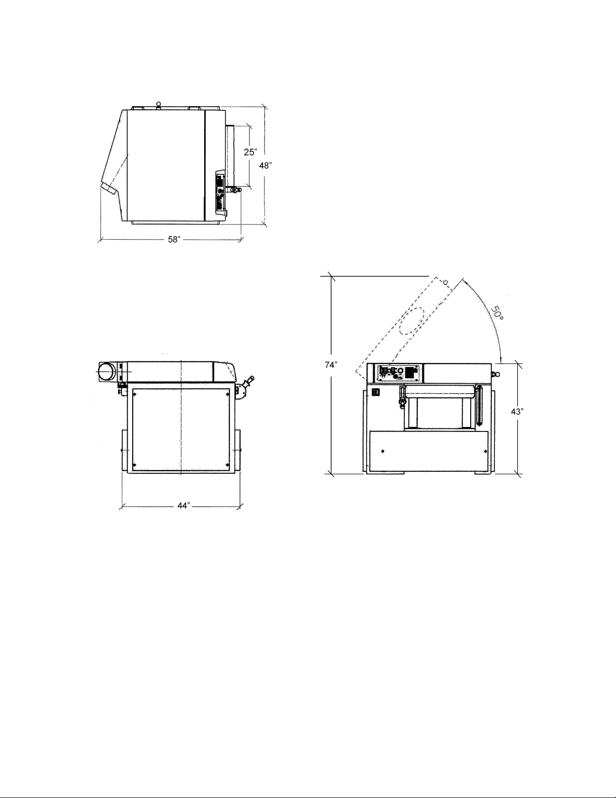
WP2412 Planer Dimensions
7
Page 8

Unpacking
Open shipping crate and check for shipping
damage. Report any damage immediately to
your distributor and shipping agent. Read this
instruction manual thoroughly for assembly,
maintenance and safety instructions.
Contents of the Shipping Container
1 Planer
3 Lifting hooks
4 Open-end wrenches (10, 13-17, 19-22, and
24mm)
5 Hex wrenches (4, 5, 6, 8 and 10mm)
1 Brass punch
1 Owner's manual
1 Warranty card
Read and understand the entire contents of this manual before attempting set-up
or operation! Failure t o co mpl y may cause seri ou s injury.
8
Page 9

Installation
Tools required for installation
wrench set (provided)
level
forklift or cr ane with straps
1. Remove the crate from around the planer
and any fasteners secur ing t he pl aner to t he
skid.
2. Remove the side covers and place t he lifting
hooks into the slot s (Figure 1). Place straps
under them and l if t t he machi ne off the ski d.
The planer should be located on a sturdy
floor, pref erably concrete, in a dry area with
sufficient lighting. Leave enough space
around the machine for loading and
offloading stock and routine maintenance
work.
3. When the planer is situated, use the leveling
screws (Figur e 2) to lev el the mac hine.
4. Exposed metal areas of the planer have
been factory coated with a protectant. This
should be removed with a soft cloth and
kerosene. Do not use an abrasive pad. Do
not let solvent contact the plastic parts of
the machine, as it may damage t hem .
Figure 1
Electrical Connections
Electrical connections must
be made by a qualified electrician in
compliance with all relevant codes. The
machine must be properly grounded to help
prevent electrical shock and possible fatal
injury.
The planer may be fitt ed with a 230 volt plug, or
may be “hard-wired” directly to your electrical
panel. If hard-wired to a panel, make sure a
disconnect i s available for the operator.
IMPORTANT: The 230 volt model of the
WP2412 planer is wired for 230 volt only; it is
not convertible to 460 volt.
1. Make sure the machine’s plug is
disconnected f rom the power source. If it is
hard-wired, m ake sure the fuses hav e been
removed or t he breakers hav e been tripped
in the circuit to which the saw will be
connected. Pl ace a warning placard on the
fuse holder or circuit breaker to prevent it
being turned on while the machine i s being
wired. Always follow proper Lock Out/Tag
Out procedures when perf orming any wiri ng
on this machine.
Figure 2
9
Page 10
2. Make sure the voltage of the power source
corresponds to the v oltage of the pl aner as
recorded on the mot or pl ate.
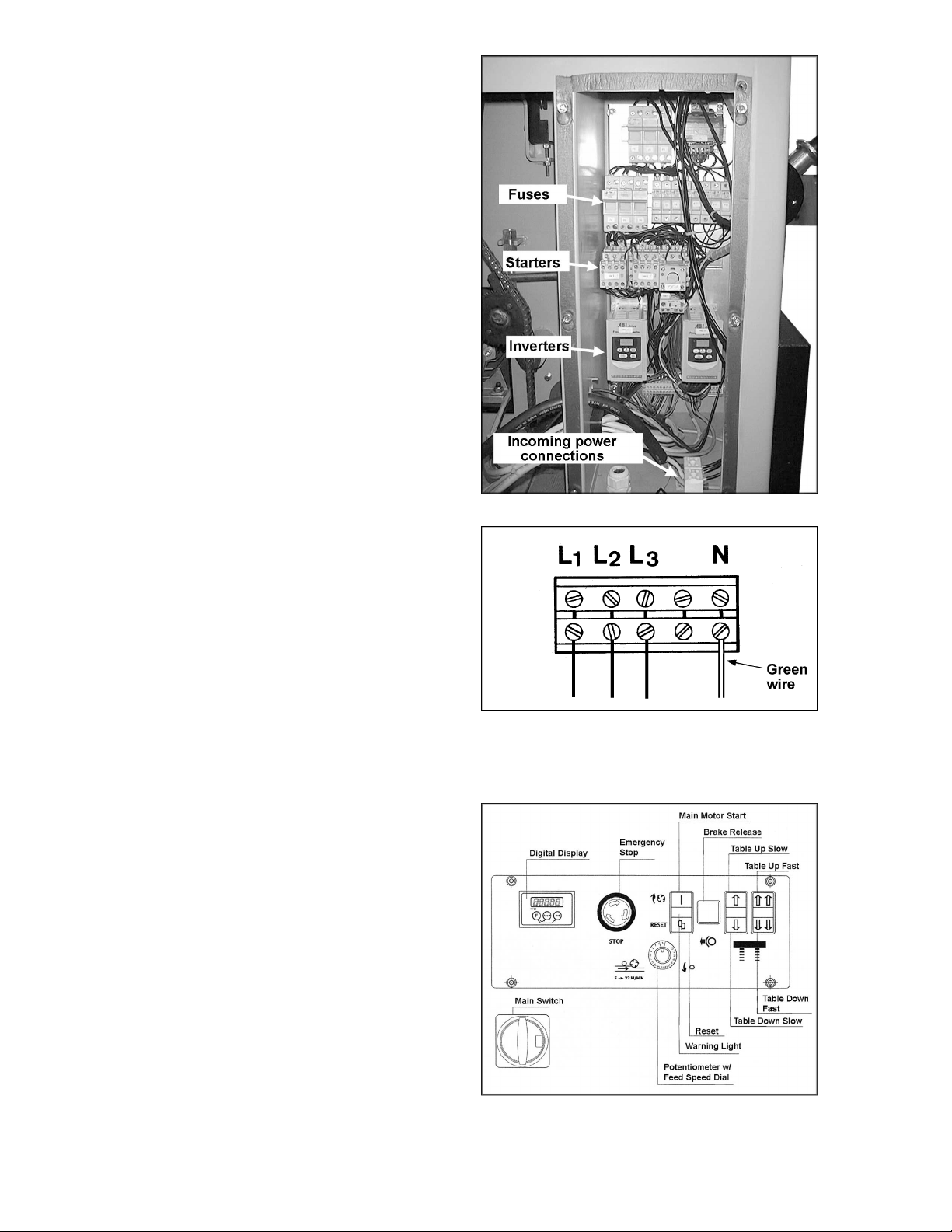
3. Open the electrical enclosure on the left
side of the machi ne (Figure 3) by loosening
the screws and sliding the panel upward.
4. Connect the three phases to the terminals
marked L1, L2, L3 (Figur e 4) .
5. Connect the green neutral wire to terminal
“N”.
6. Connect the mac hine to power (or install t he
fuses or reset the breakers at the power
source).
7. Test the rotation of the cutterhead. Turn on
the main power switch (see Figure 5) and
then the main m otor switch (Figure 5) . The
pulley on the main mot or (on the side near
the electrical enclosure) should rotate
counterclockwise. If it rotates clockwise,
stop the machine with the red stop button
(Figure 5 ).
8. Disconnect machine from power source,
and exchange leads L1 and L2.
Figure 3
9. Reconnect power, and close the electrical
cover.
Dust Collection
It is strongly recommended this planer be
connected to a dust extraction system, via the 6”
(160mm) dust port at the rear of the planer. Your
dust collector should have at least 1500 CFM
capacity.
Adjustments
Controls
Figure 5 shows the control panel for the planer.
Starting procedure
NOTE: The planer will not start if the hood is
raised, or if the brake release light is on (see
below).
1. Turn Main Switch to position “I”. [NOTE: The
main switch has a lock-out hole, through
which a padlock or similar device can be
inserted, when the swit c h is in “O” position]
Figure 4
2. Push the Mai n M otor S tart butt on; t he mot or
will start in Star-Delta. After a few seconds
you will hear the motor switch over to full
speed operation. NOTE: The inverters (see
Figure 3) have been factory programmed
and their setti ngs should not be altered.
Figure 5
10
Page 11

3. The Reset button (Figure 5) will light up if
the machine becomes overloaded. Press
this button to re- start the machine.
4. The Emergenc y Stop Butt on shuts down all
operations on the planer. An automatic
brake stops the m otor within 10 secon ds. A
similar stop but ton can be found at the back
of the machine. To restart the machine,
simply twist the stop button and allow it to
pop back up
5. To begin the feed motor and rotati on of the
feed roll ers, press the Potentiom eter button
on the dial. Rotate the dial to set the feed
speed. Speed ranges fr om 16 to 72 feet per
minute. The num bers on the dial are shown
as 1 to 11; the higher t he number , t he faster
the speed. To stop the feed mot or press the
Potentiom eter butt on again.
6. The Brake Release switch frees the
cutterhead so t hat it can be mov ed by hand
(e.g. when changing knives). When the
brake release is o n, the switch stays lit. As a
safety feature, the planer’s motor will not
start if t he brake release switch is l it. And if
the switch i s pushed during operat ions, the
motor will automatically stop. To restart the
planer, de-press the brake release switch;
the light will turn off.
7. To raise the table press the up-arrow
buttons; to l ower the table pr ess the downarrow buttons. The single arrows raise the
table slowly, t he double arrows rapidly.
Calibrating Digital Display
Before operating the planer, the digital display
should be checked for accuracy and c alibrated if
necessary. Use a scrap board.
1. Set the table to just under t he thickness of
your scrap board, u si ng the scale next to t he
table (Fi gure 6). Feed t he board thr ough the
planer to achiev e a planed si de.
2. Raise the table slightly until the adjoining
scale pointer is set evenly on a number.
3. Fli p the board over and f eed it through the
planer, then c arefully measure it s thickness
with calipers. Compare this with the digital
display.
4. If the display needs correcting, press and
hold “Function,” and press “Reset”. The
display will return to zero.
5. Press and hold “Function,” and press “Set”
until the di splay shows the thi ck ness of your
board. Tapping the “Set” button will move
the display by increments; hol ding down the
“Set” button will move the display rapidly.
Figure 6
11
Page 12

Changing Fuses
Disconnect pl aner f rom power source, and o pen
the electri cal enclosure. Pull open the cov er on
a fuse holder, as shown in Figure 7, and slide
out the old f use. Replace it with a new one of
the proper amperage. Close the cover.
Do not use a fuse with
amperage rating different than what is listed
on the cover of the fuse holder.
Changing Knives
The planer has a Ters aTM Monobloc cutt erhead.
Knife changing is simple, and the two-sided
knives are self seating once the cutterhead
begins rotating. Tersa
from your dealer or most woodworking supply
stores.
Do not l oosen any screws o n
the cutterhead .
1. Push brake release button (see Figure 5).
The brake release light will come on.
2. Pull out on the lever at the ri ght side of the
machine, and r aise the hood.
After prolonged use of the
planer, the cast iron frame and areas aroun d
the cutterhead may be hot.
3. Disconnect machine from power source.
4. Rotate the cutterhead to gain access to a
knife. Use the provided brass punch to
gently tap down the segmented gibs, as
shown in Figure 8. This will release the
knife.
TM
knives are available
Figure 7
Figure 8
5. Align the knife and caref ully slide it through
the hole in the side of the bearing casting
(Figure 9).
6. To install a new knife (or the same knife
reversed for a new edge), insert it through
the hole. Make sure the knife is properly
seated upon the bead (Figure 8) and the
ends are not prot rudi ng past t he end s of the
cutterhead. When the machine is started
later, the gibs will automatically secure the
knife in place.
7. Repeat this procedure for the other three
knives.
8. Lower the hood and reconnec t power to t he
machine. Press the brake release button
(Figure 5). The warning light will go out.
Figure 9
12
Page 13

9. After adjusting or changing knives, the
digital display should be checked and
recalibrated if necessary. See “Calibrating
Digital Displ ay .”
Belt Tension & Replacement
Note: Belts should be replaced as a matched set
of three.
1. Loosen the three bol ts (A, Fi gure 10) which
hold the motor support br ac k et to the frame.
2. Turn the hex nuts (B, Figure 10) on the
tension rod as needed.
3. When finished, tighten the three bolts (A,
Figure 10).
Drive Chain Replacement
The drive chains do not require tension
adjustment, since tension is always assured
by an idle chain tensi oner ( C, Fi gur e 11) .
To replace the main drive chain, pull the
tensioner (C, Figure 11) backward and
remove the c hain from around the sprockets.
When the new chain has been mounted,
always make sure the ten sioner is well plac ed
on the chain.
To replace the chain for the table raising
mechanism, pull the lever (D, Figure 12) to
the back and remove the chain. When the
new chain has been m ounted, pu sh the lev er
(D, Figure 12) bac k into posi tion.
Figure 10
Figure 11
Do not tu rn th e sprockets o n
the table raising screws with the chain
removed. Doing so will mi sali gn the t abl e.
Figure 12
13
Page 14

Feed Rollers
The infeed and out feed rollers and chipbreaker
have been factory set. However, if spring
tension adjustment should ever be necessary,
use the appropriate adjustment assembly
located beneath the lip of the frame – one is
shown in Figure 13.
1. Loosen the nut and t urn the screw in or out.
When finished, tighten nut.
2. Perform the same adjustment at the
opposite end of the rol ler.
Table Rollers
The table roll ers can be raised or lowered with
the handle (Figure 14). A label is affixed near
the handle for ref er enc e.
Maintenance
Before any intervention on
the machine, di sconnect it from the electrical
supply by pulling out the plug or switching
off the main switch! Follow lockout/tagout
procedures. Failure to comply may cause
serious injury.
The anti-kickback fingers m ust hang down f reely
and operate independently by gravity. They
should be inspected frequently and cleaned
whenever necessary.
Figure 13
Figure 14
The table should be k ept clean and free of rust
or deposits.
The lead screws and posts beneath the table,
and the driv e chains, should be kept clean and
oiled.
Periodic ally blow out saw dust from the motor’s
cooling fan.
14
Page 15

Troubleshooting: Operating Problems
Trouble Probable Cause Remedy
Table rollers not set pr oper ly. Adjust rollers to proper height.
Snipe
(NOTE: Snipe can be
minimized but not
eliminated)
Fuzzy Grain
Torn Grain
Rough or Raised
Grain
Inadequate support of long boards.
Uneven feed roller pressure front to
back.
Dull knives. Reverse or replace knives.
Lumber not butted properly.
Planing wood with high moisture
content.
Dull knives. Reverse or replace knives.
Too heavy a cut. Adjust proper dept h of cut.
Knives cutting against grain. Cut along the grain.
Dull knives. Reverse or replace knives.
Dull knives. Reverse or replace knives.
Too heavy a cut. Adjust proper dept h of cut.
Moisture cont ent too high.
Support long boards wit h ex tension
rollers.
Adjust feed roller tension.
Butt end to end each piece of stock
as they pass through.
Remove moisture content from wood
by drying, or choose other stoc k .
Remove moisture content from wood
by drying, or choose other stoc k .
Rounded, glossy
surface
Poor feeding of
lumber
Dull knives. Reverse or replace knives.
Feed speed too slow. Increase speed.
Cutting dept h too shal low. Increase depth.
Adjust feed roller tension. If proper
Inadequate f eed r oller pressure.
Planer bed rought or dirty.
Transmission v-belt slipping. Tighten transmission v-belt.
Surface of feed rollers too smooth.
Bed rollers too low.
tension cannot be achieved, replace
feed rollers.
Clean pitch and residue, and wax
planer tabl e.
Lightly roughen t he feed roller surface
with sandpaper.
Raise bed roll er s to proper dept h for
stock.
15
Page 16

Troubleshooting : Mechanical & Electrica l Problems
Trouble Probable Cause Remedy
Board thickness does
not match digital
display
Digital displ ay not calibrated properly. Foll ow calibration procedures.
Chain jumping
Machine will not
start/restart or
repeatedly t rips
circuit breaker or
blo ws fu ses.
Inadequate chain tension. Adjust chai n tension.
Sprockets mi sali gned. Align sprockets.
Sprockets worn. Replace sprockets.
No incoming power.
Overload aut omatic reset has not
reset.
Planer frequently trips.
Verify unit is connected to power, and
main switch is set to “I”.
When planer overl oads on the ci r c uit
breaker built into the motor starter, it
takes time for the machine to cool
down before restar t. Allow unit to
adequately cool bef ore attempting
restart. If pr oblem persists, check
amp setting on the mot or start er
inside the electrical enclosure.
One cause of overl oading trips which
are not electric al in nature is too
heavy a cut. The solution is to take a
lighter cut. If too deep a c ut is not t he
problem, then chec k the amp setting
on the overload rel ay . Match the full
load amps on the motor as noted on
the motor plate. If amp setting is
correct then ther e is probably a loose
electric al lead. Check amp setting on
motor starter.
Building circuit breaker trips or fuse
blows.
Loose electri c al c onnec tions.
Motor starter failure.
Verify that planer is on a circuit of
correct size. If circuit size is correct,
there is probabl y a loose el ectr ic al
lead. Check amp setting on motor
starter.
Go through all the electrical
connections on the planer including
motor connecti ons, verifying the
tightness of each. Look for any signs
of electrical ar ci ng whic h is a sure
indicator of loose connections or
circuit overload.
Examine motor star ter for burned or
failed component s. If damage is
found, replace motor starter. If motor
starter look s okay but is still suspect,
you have two options: Have a
qualified elec trician test the motor
starter for function, or purchase a new
starter and establish if that was the
problem on changeout . (continued)
16
Page 17

Trouble Probable Cause Remedy
Machine will not
start/restart or
repeatedly t rips
circuit breaker or
blo ws fu ses.
Motor starter failure.
Motor failure.
Miswiring of the unit.
If you have access to a voltmeter, you
can separate a starter f ailure from a
motor fai lu re by fi r st, verify ing
incoming voltage at 220+/-20 and
second, checking the voltage
between starter and motor at 220+/-
20. If incoming voltage is incorrect,
you have a power supply problem. If
voltage between start er and m otor is
incorrect, y ou hav e a starter pr oblem.
If voltage bet ween start er and m otor
is correct, you hav e a motor pr oblem .
If electri c mot or i s suspect, you have
two options: Have a qualified
electrician test the motor for function
or remove the motor and take it t o a
qualified elec tric motor repair shop
and have it tested.
Double check to confirm all electrical
connections are cor r ec t and properly
tight. The elect ri c al c onnec tions other
than the motor are pre- assembled
and tested at the factory. Therefore,
the motor connections should be
double checked as the highest
probability for error. If problems
persist, double c hec k the factory
wiring.
On/off switch failure.
If the on/off switch is suspect, you
have two options: Hav e a qualified
electrician test the switch for function,
or purchase a new on/off switc h and
establish if that was the pr oblem on
changeout.
17
Page 18

Replacement Parts
Replacement part s are li sted on the f ollowing page s. To order par ts or reac h our servi ce depar tment, call
1-800-274-6848 between 7:00 a.m. and 6:00 p.m. (CST), Monday through Friday. Having the Model
Number and Serial Number of your machine available when you call will allow us to serve you quic kly and
accurately.
18
Page 19

Parts List: Drawing No. 1
Index No. Part No. Description Size
1............... WP2412-101........... Outfeed Roll er ...................................................
2............... WP2412-102........... Chipbreaker Section..........................................
2a.............WP2412-102A......... Chipbreaker Section Spacer..............................
3............... WP2412-103........... Spring Bar.........................................................
3a.............TS-1504081............Socket Head Cap Screw........................M8 x 40
4............... WP2412-104........... Spring................................................................
5............... WP2412-105........... Socket Set Screw................................M16 x 16
6............... WP2412-106........... Suction Outlet Cover..........................................
6a.............WP2412-106A......... Dust Hood Assembly .........................................
7............... WP2412-107........... Chipbreaker Axle...............................................
8............... WP2412-108........... ABS Chip Deflector............................................
8a.............TS-1482021............Hex Cap Scr e w......................................M6 x 12
8b.............TS-1550041............Flat Washe r.................................................. M6
10.............WP2412-110........... Tersa
11.............WP2412-111........... Infeed Roller Axle ..............................................
11a...........WP2412-111A......... Infeed Section Spacer........................................
11b...........WP2412-111B......... Infeed Serrated Roller Section ...........................
11c...........WP2412-111C......... Infeed Roller S ection S pri ng...............................
11d...........WP2412-111D......... Complete Infeed Roll Assembly .........................
12.............WP2412-112........... Chipbreaker Section..........................................
12a...........WP2412-112A......... Chipbreaker Section Spacer..............................
13.............WP2412-113........... Anti-K ic k b a ck Finger..........................................
13a...........WP2412-113A......... Anti-K ic k b a ck Finger Spacer..............................
14.............WP2412-114........... Anti-K ic k b a ck Finger Axle..................................
15.............WP2412-104........... Spring................................................................
16.............WP2412-116........... Chipbreaker Axle...............................................
17.............WP2412-103........... Spring Bar.........................................................
17a...........TS-1504081............Socket Head Cap Screw........................M8 x 40
18.............WP2412-105........... Socket Set Screw................................M16 x 16
19.............TS-2279351............Socket Set Screw................................M10 x 35
20.............TS-1540071............Hex Nut.......................................................M10
21.............WP2412-121........... Planer Table......................................................
22.............TS-1525041............Socket Set Screw................................M10 x 20
23.............WP2412-123........... Roller Actuator Axle...........................................
24.............WP2412-124........... Roller Raise Eccentrics......................................
25.............WP2412-125........... Roller Raise Actuator.........................................
26.............WP2412-126........... Strip...................................................................
27.............TS-1550061............Flat Washe r.................................................. M8
28.............TS-1490061............Hex Cap Scr e w......................................M8 x 35
29.............WP2412-129........... Spacer...............................................................
30.............WP2412-130........... Right Brace........................................................
30a...........WP2412-130A......... Left Brace..........................................................
31.............WP2412-131........... Table Column....................................................
32.............WP2412-132........... Table Raise Nut.................................................
33.............TS-1524051............Socket Set Screw..................................M8 x 20
34.............TS-1490031............Hex Cap Scr e w......................................M8 x 20
35.............WP2412-135........... Upper Column Disc............................................
36.............WP2412-136........... Table Column Seal Ring....................................
37.............WP2412-137........... Lower Column Backup Disc...............................
38.............WP2412-138........... Table Raising Screw..........................................
38a...........WP2412-138A......... Table Raising Screw Assembly..........................
41.............BB-51104................Table Raise Screw Bearing ......................51104
43.............BB-51104................Table Raise Screw Bearing.......................51104
46.............TS-1490051............Hex Cap Scr e w......................................M8 x 30
47.............TS-1550061............Flat Washe r.................................................. M8
48.............WP2412-148........... Bearing Housing................................................
TM
Monobloc Cutt erhead............................
19
Page 20

Index No. Part No. Description Size
49.............WP2412-149........... Table Raise Sprocket.........................................
50.............WP2412-150........... Spacer Disc.......................................................
................. WP2412-151........... Top Cover Plate (not shown)..............................
................. WP2412-152........... Rear Frame Reinforcement (not shown).............
................. WP2412-153........... Top Cover Corner Strip (not shown)...................
................. WP2412-154........... Brass Punch - Knife Change (not shown)...........
20
Page 21

Drawing No. 1
21
Page 22

Parts List: Drawing No. 2
Index No. Part No. Description Size
1............... TS-1541041 ............ Nylon Insert Locknut....................................M10
2............... TS-1550071 ............ Flat Wash er.................................................M10
3............... WP2412-203........... Upper Feed Roller Adjust Stud...........................
4............... WP2412-204........... Feed Roller Bearing Housing .............................
5............... WP2412-205........... Outfeed Roll er F eed Chain ................................
6............... WP2412-206........... E-Stop Housing .................................................
7............... WP2412-207........... Short Chain Tensioner Assembly.......................
8............... WP2412-208........... Tensioner Spring ...............................................
9............... WP2412-209........... Hood Raising Lift ...............................................
10.............WP2412-208........... Tensioner Spring ...............................................
11.............WP2412-211........... Long Chain Tensioner Assembly........................
12.............WP2412-212........... Feed Chain........................................................
13.............TS-1541031............Nylon Insert Locknut..................................... M8
15.............WP2412-215........... Lower Feed Roller Adjust Stud ...........................
16.............TS-1540061............Hex Nut........................................................ M8
17.............WP2412-217........... Feed Roller Pressure Bracket ............................
18.............WP2412-218........... Feed Roller Pressure Spring..............................
19.............WP2412-219........... Table Roller Handle...........................................
20.............WP2412-220........... Handle Spring....................................................
21.............WP2412-221........... Locking Handle..................................................
22.............WP2412-222........... Lever.................................................................
23.............TS-1504041............Socket Head Cap Screw........................M8 x 20
24.............WP2412-224........... Bushing.............................................................
25.............WP2412-123........... Roller Actuator Axle...........................................
26.............TS-1525041............Socket Set Screw................................M10 x 20
27.............WP2412-227........... Handle Cover Plate............................................
22
Page 23

Drawing No. 2
23
Page 24

Parts List: Drawing No. 3
Index No. Part No. Description Size
1............... WP2412-301........... Main Bearing Housing, Left................................
2............... BB6209VV ............. Cutterhead Bearing.............................6209-2RS
3............... WP2412-303........... Retaining Ring...................................................
4............... WP2412-304........... Disc...................................................................
5............... TS-2312241 ............ Hex Jam Nut................................................M24
6............... WP2412-306........... Hood Latch........................................................
7............... WP2412-307........... Hood Latch Pin..................................................
8............... WP2412-308........... Main Bearing Housing, Right..............................
9............... TS-1524051 ............ Socket Set Screw..................................M8 x 20
10.............WP2412-310........... Cutterhead Pulley..............................................
12.............WP2412-312........... Disc...................................................................
13.............TS-1515031............Socket Head Flat Screw.........................M8 x 25
14.............WP2412-314........... Hood Hinge .......................................................
15.............WP2412-315........... Hinge Pin, Front.................................................
15a...........WP2412-315A......... Hinge Pin, Rear.................................................
16.............WP2412-316........... Hinge Reinforcement Plate ................................
17.............TS-1515031............Socket Head Flat Screw.........................M8 x 25
18.............TS-1504041............Socket Head Cap Screw........................M8 x 20
19.............WP2412-319........... Adjustment Nut..................................................
20.............WP2412-320........... Belt Adjustment Rod..........................................
21.............WP2412-321........... Drive Belts.........................................................
22.............WP2412-322........... Motor Pulley.............................38mm arbor dia.
23.............WP2412-323........... Washer..............................................................
24.............TS-1515041............Socket Head Flat Screw.........................M8 x 30
25.............WP2412-325........... Frame Leveling Bolt...........................................
25a...........WP2412-325A......... Leveling Bolt Nut................................................
24
Page 25

Drawing No. 3
25
Page 26

Parts List: Drawing No. 4
Index No. Part No. Description Size
1............... WP2412-401........... Hood Handle......................................................
2............... WP2412-121........... Planer Table......................................................
3............... BB6003VV ............. Table Roller Bearing........................... 6003-2RS
4............... WP2412-404........... Table Roller.......................................................
5............... WP2412-405........... Bushing.............................................................
6............... TS-1490041 ............ Hex Cap Screw......................................M8 x 25
7............... TS-1550061 ............ Flat Wash er.................................................. M8
8............... WP2412-125........... Roller Raise Actuator.........................................
9............... WP2412-409........... Side Strip...........................................................
10.............BB6003VV ............. Table Roller Bearing...........................6003-2RS
12.............TS-1491041............Hex Cap Scr e w....................................M10 x 30
13.............WP2412-413........... Feed Axle..........................................................
14.............WP2412-414........... Feed Unit Assembly ...........................................
15.............BB-6006VV ............ Feed Unit Bearing...............................6006-2RS
16.............WP2412-416........... Retainer Ring.....................................................
17.............WP2412-417........... Sprocket............................................................
18.............WP2412-418........... Sprocket Spacer................................................
19.............TS-1550061............Flat Washe r.................................................. M8
20.............TS-1490031............Hex Cap Scr e w......................................M8 x 20
21.............WP2412-421........... Retaining Ring...................................................
22.............WP2412-422........... Spacer...............................................................
23.............BB-6003VV ............ Bearing...............................................6003-2RS
24.............WP2412-424........... Sprocket Assembly............................................
25.............WP2412-425........... Retainer Ring.....................................................
26.............WP2412-426........... Bushing.............................................................
27.............BB-6003VV ............ Bearing...............................................6003-2RS
28.............BB-6005VV ............ Feed Roller Beari ngs ..........................6005-2RS
29.............WP2412-429........... Retaining Ring...................................................
30.............WP2412-430........... Bushing.............................................................
31.............WP2412-105........... Socket Set Screw................................M16 x 16
32.............WP2412-432........... Outfeed Roller Sprocket Mount..........................
32a...........WP2412-432A......... Infeed Roller Sprocket Mount.............................
33.............WP2412-433........... Sprocket............................................................
34.............WP2412-434........... Spacer...............................................................
35.............WP2412-433........... Sprocket............................................................
36.............WP2412-436........... Bushing Spacer.................................................
37.............TS-2342161............Nylon Insert Locknut....................................M16
38.............TS-155010..............Flat Wash er.................................................M16
26
Page 27

Drawing No. 4
27
Page 28

Parts List: Drawing No. 5
Index No. Part No. Description Size
1............... WP2412-501........... Main Motor............................. 15HP, 230V, 3Ph
2............... WP2412-502........... Feed Motor with Reducer.............................1HP
3............... WP2412-503........... Spring................................................................
4............... WP2412-504........... Gear Box Mounting Plate...................................
5............... WP2412-505........... Table Raising Chain...........................................
6............... TS-1550061 ............ Flat Wash er.................................................. M8
7............... TS-1490111 ............ Hex Cap Screw......................................M8 x 60
8............... WP2412-508........... Front Cover.......................................................
9............... WP2412-509........... Side Cover.........................................................
10.............TS-1490081............Hex Cap Scr e w......................................M8 x 45
11.............WP2412-511........... Plate..................................................................
12.............WP2412-512........... Plate Spanner....................................................
13.............WP2412-513........... Support Plate .....................................................
14.............WP2412-514........... Toothed Lever ...................................................
15.............WP2412-515........... Spring................................................................
16.............WP2412-516........... Adjustment Pawl................................................
17.............WP2412-517........... Table Raise Motor with Reducer...............3/4HP
18.............WP2412-518........... Rear Cover........................................................
19.............TS-1490111............Hex Cap Scr e w......................................M8 x 60
20.............TS-1550061............Flat Washe r.................................................. M8
................. WP2412-LH ............ Lifting Hooks (not shown)...................................
28
Page 29

Drawing No. 5
29
Page 30

Parts List: Electrical Box
Index No. Part No. Description Size
A ..............W P2412-601...........Fuse Holder...................................3 poles, 50 A
B ..............W P2412-602...........Fuse Holder......................................1 pole, 32A
C.............. WP2412-603........... Magnetic Starter................................................
D.............. WP2412-604........... Auxiliary Contact................................................
E ..............W P2412-605...........Mechanical Interlock between Mag. Starters......
F...............WP2412-606...........Timer Relay Star-Delta......................................
G..............WP2412-607........... Thermal Overload Relay....................................
H.............. WP2412-608........... Transformer.......................................................
I ................WP2412-609........... Frequency V ari ator............................................
30
Page 31

Electrical Box
31
Page 32

Parts List: Control Panel
Index No. Part No. Description Size
J...............W P2412-701...........Main On-O ff S witch............................................
K ..............W P2412-702...........ELGO Read-out Z 20.........................................
L............... WP2412-703........... E-Stop Operator.................................................
M..............WP2412-704........... Motor On/Table Reset Operator.........................
N.............. WP2412-705........... Brake Release Operator....................................
O..............WP2412-706........... Table Slow Operator..........................................
P ..............W P2412-707...........Table Fast Operator...........................................
Q..............WP2412-708........... Potentiometer....................................................
................. WP2412-709........... ELGO Magnetic Tape ........................................
................. WP2412-710........... Sensor Cable.....................................................
................. WP2412-711........... Hood Limit Switch..............................................
................. WP2412-712........... Fuse............................................................50A
................. WP2412-713........... Fuse............................................................40A
................. WP2412-714........... Fuse..............................................................6A
................. WP2412-715........... Fuse..............................................................2A
................. WP2412-716........... Fuse..............................................................1A
................. WP2412-717........... Open Contact ....................................................
................. WP2412-718........... Closed Contact..................................................
32
Page 33

Electrical Connections – 230 Volt
33
Page 34

Electrical Connections – 230 Volt
34
Page 35

35
Page 36

WMH Tool Gr ou p
2420 Vantage Drive
Elgin, Illinois 60123
Phone: 800-274-6848
www.wmhtoolgroup.com
36
 Loading...