

Page 1
This .pdf document is bookmarked
Operating Instructions and Parts Manual
Rout-R-Lift® and Fence Assembly
Item No. 6682004
Powermatic
427 New Sanford Rd.
LaVergne, TN 37086 Part No. M-0460261
Ph.: 800-274-6848 Revision D3 01/2014
www.powermatic.com Copyright © 2014 Powerm atic
Page 2

Warranty and Service
JET, Wilton and Powermatic warrants every product they sell against manufacturers’ defects. If one of our tools
needs service or repair, please contact Technical Service by calling 1-800-274-6846, 8AM to 5PM CST, Monday
through Friday
Warranty Period
The general warranty lasts for the time period specified in the literature included with your product or on the official
JET, Wilton or Powermatic branded websites.
• JET, Wilton and Powermatic products carry a limited warranty which varies in duration based upon the
product. (See chart below)
• Accessories carry a limited warranty of one year from the date of receipt.
• Consumable items are defined as expendable parts or accessories expected to become inoperable within a
reasonable amount of use and are covered by a 90 day limited warranty against manufacturer’s defects.
Who is Covered
This warranty covers only the initial purchaser of the product from the date of delivery.
What is Co vered
This warranty covers any defects in workmanship or materials subject to the limitations stated below. This warranty
does not cover failures due directly or indirectly to misuse, abuse, negligence or accidents, normal wear-and-tear,
improper repair, alterations or lack of maintenance.
Warranty Limitations
Woodworking products with a Five Year Warranty that are used for commercial or industrial purposes default to a
Two Year Warranty. Please contact Technical Service at 1-800-274-6846 for further clarification.
How to Get Technical Support
Please contact Technical Service by calling 1-800-274-6846. Please note that you will be asked to provide pro of
of initia l p u rch a s e whe n calling. If a product requires further inspection, the Technical Service representative will
explain and assist with any additional action needed. JET, Wilton and Powermatic have Authorized Service Centers
located throughout the United States. For the name of an Authorized Service Center in your area call 1-800-274-6846
or use the Ser vice C enter Lo cator on t he JET, Wi lton or Powerma t ic web si te.
More Informa t ion
JET, Wilton and Powermatic are consistently adding new products. For complete, up-to-date product information,
check with your local distributor or visit the JET, Wilton or Powermatic website.
How S tat e Law A pplies
This warranty gives you specific legal rights, subject to applicable state law.
Limitations on This Warranty
JET, WILTON AND POWERMATIC LIMIT ALL IMPLIED WARRANTIES TO THE PERIOD OF THE LIMITED
WARRANTY FOR EACH PRODUCT. EXCEPT AS STATED HEREIN, ANY IMPLIED WARRANTIES OF
MERCHANTABILITY AND FITNESS FOR A PARTICULAR PURPOSE ARE EXCLUDED. SOME STATES DO NOT
ALLOW LIMITATIONS ON HOW LONG AN IMPLIED WARRANTY LASTS, SO THE ABOVE LIMITATION MAY NOT
APPLY TO YOU.
JET, WILTON AND POWERMATIC SHALL IN NO EVENT BE LIABLE FOR DEATH, INJURIES TO PERSONS OR
PROPERTY, OR FOR INCIDENTAL, CONTINGENT, SPECIAL, OR CONSEQUENTIAL DAMAGES ARISING FROM
THE USE OF OUR PRODUCTS. SOME STATES DO NOT ALLOW THE EXCLUSION OR LIMITATION OF
INCIDENTAL OR CONSEQUENTIAL DAMAGES, SO THE ABOVE LIMITATION OR EXCLUSION MAY NOT APPLY
TO YOU.
JET, Wilton and Powermatic sell through distributors only. The specifications listed in JET, Wilton and Powermatic
printed materials and on official JET, Wilton and Powermatic-branded websites are given as general information and
are not binding. JET, Wilton and Powermatic reserve the right to effect at any time, without prior notice, those
alterations to parts, fittings, and accessory equipment which they may deem necessary for any reason whatsoever.
®
branded products are not sold in Canada by JPW Industries, Inc.
JET
Product Listing with Warranty Period
90 Days – Parts; Consumable items; Light-Duty Air Tools
1 Year – Motors; Machine Accessories; Heavy-Duty Air Tools; Pro-Duty Air Tools
2 Year – Metalworking Machinery; Electric Hoists, Electric Hoist Accessories
5 Year – Woodworking Machinery
Limited Lifetime – Wilton branded products; JET Parallel clamps; Manual Hoists; Manual Hoist Accessories;
Shop Tools; Warehouse & Dock products; Hand Tools
NOTE: JET, Wilton and Powermatic are divisions of JPW Industries, Inc.. References in this document to JET,
Wilton and/or Powermatic also apply to JP W Indus trie s, Inc., or any of its succe ssors in inte re st to the JET, Wilton
and/or Powermatic brands.
2
Page 3

Table of Contents
Warranty and Servic e .............................................................................................................................. 2
Table of Contents .................................................................................................................................... 3
Mounting Your Router to the Rout-R-Lift .................................................................................................. 4
Leveling th e Ro u t-R - L i ft ........................................................................................................................... 6
Mounting the Del ux e Fence A ssembly ..................................................................................................... 7
Using Your Rout-R-Lift ............................................................................................................................. 9
Modification for Height Adjustment Tension ........................................................................................... 10
Replacement Parts ................................................................................................................................ 10
Rout-R-Lift Deluxe Fence Assembly ................................................................................................... 11
Rout-R-Lift A ssembly – Exploded View .............................................................................................. 12
Rout-R-Lift Assembly – Parts List ....................................................................................................... 13
Router Hole Patterns ............................................................................................................................. 14
Router Hole Patterns (continued) ........................................................................................................... 15
Making a Cut-out for the Rout-R-Lift....................................................................................................... 1 5
3
Page 4
Disconnect the table saw
from the power source before attempting any
assembly or adjustment. Failure to comply
may cause serious injury.
Contents of the Shipping Container
1 Rout-R-Lift
1 Adjustment Handle
1 Phenolic Insert 1-1/2"
1 Insert Wrench
1 5/32 Hex Wrench
1 1/8 Hex Wrench
10 1/4-28 Socket Set Scr ews
1 Starting Pin
1 Aluminum Fence Bracket
2 Aluminum Fence Extensions
2 MDF Sub Fences
1 Hardware Package
2 Fence Clamping Knobs
2 Guard Clamping Knobs
1 Plastic Fence Guard
1 Assembly Instructions
1 Warranty Registration Car d
Additional tools requir ed to mount your router to
the Rout-R-Lift:
Cross-point (P hillips) screwdriver
Tools required for adjus tment:
7/16" Open End Wrench
Mounting Your Router to the Rout-R-Lift
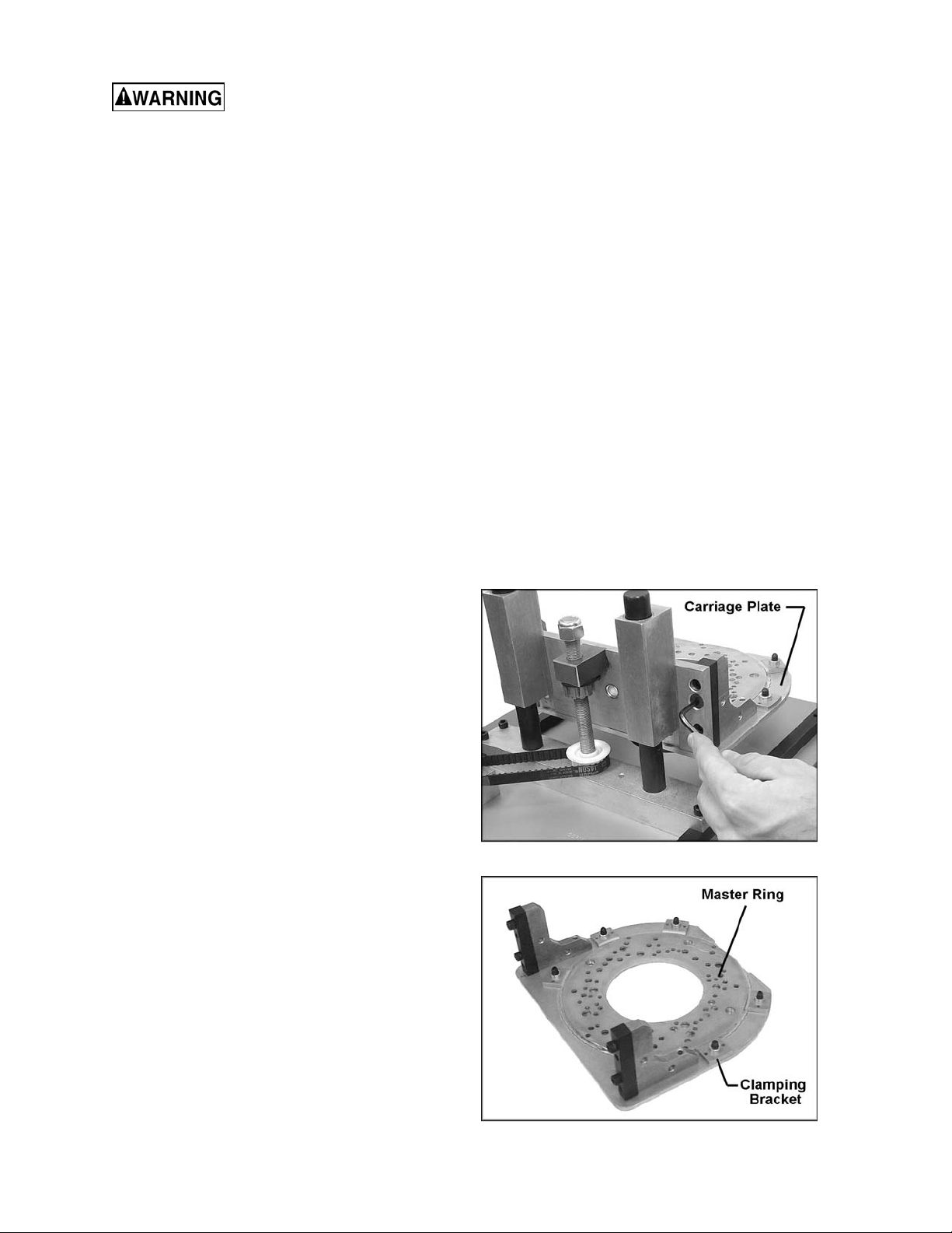
1. Turn your Rout-R-Lift upside down on the
table. With the 5/32 hex wrench supplied,
remove the four 1/4-20 x 1 flat head cap
screws (Figur e 1) and remov e the aluminum
carriage plate. (NOTE: If the screws are
blocked, crank the Rout-R-Lift with the
adjustment handle until all four screws are
exposed.)
2. Remove the master ring from the carriage
plate, by f irst removing t he six 1/4-20 x 3/4
flat head machine screws that secure the
clamping brack ets to the aluminum carri age
plate (Fig. 2).
3. Remove the sub-base and screws that
attach the sub-ba se to yo ur rout er. NOT E: If
your sub-base cannot be removed, just
remove the screws that will be used to
attach your r outer to the master ring.
4. Lay the master ring on a flat surface with the
countersunk holes and t he engraving f acing
upwards and with t he engraved "T" to the
top and the engraved " B" to the bot tom.
Figure 1
Figure 2
4
Page 5
5. Pages 14-15 show a series of drawings of
the master r ing with the holes shaded sol id
to match many differ ent routers. Locat e y our
router and then locate the proper holes in
the master r ing usi ng the dra wing a s an ai d.
With a f elt tip marker or pencil, mark a l ine
on the master r ing for each hole that you will
be using for your router.
6. With the holes marked on the master ring,
place the master ring on the base of your
router and rotate it to line up the correct
holes in your router. Don't worry about
handle locati on at this point as that can be
set when the master ring is re-attached to
the aluminum carriage plate.
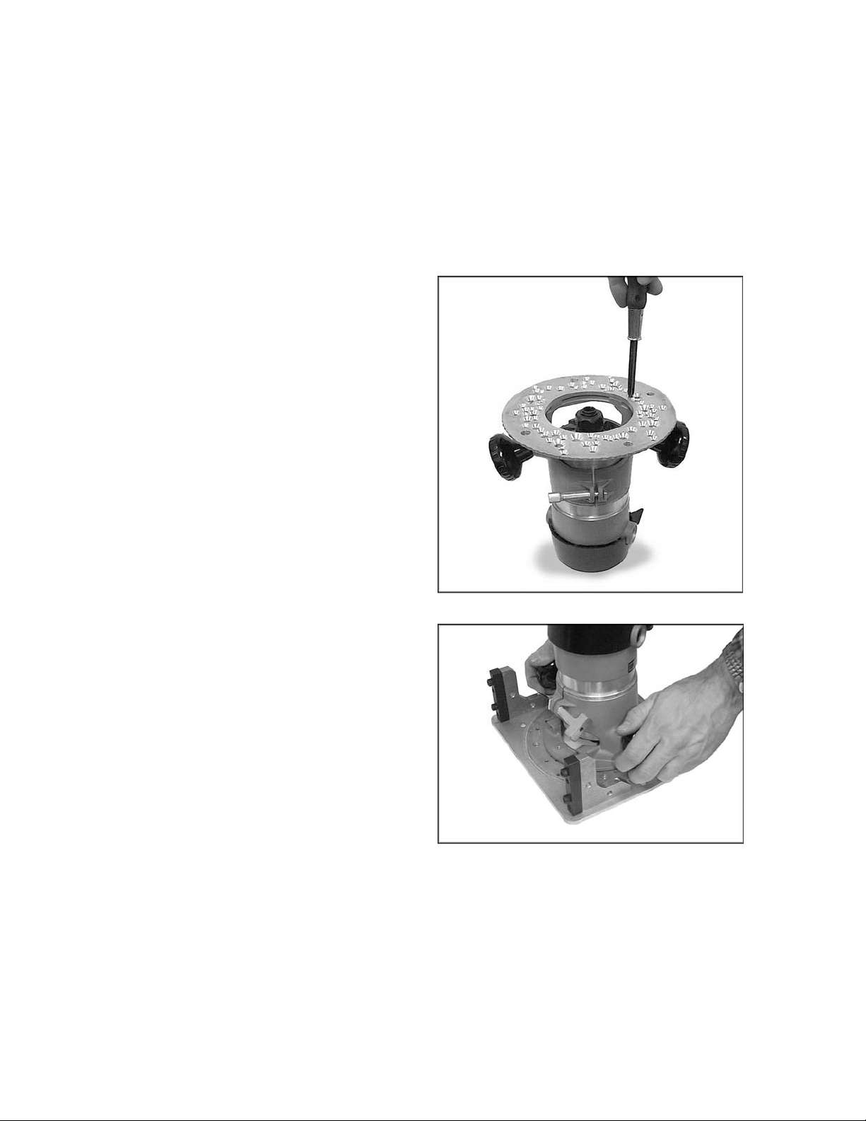
7. The master ring is 1/4" thick and may
prevent your screws that come with your
router from engaging your r outer sufficiently.
If this is the case, source longer flat head
screws from your local hardware or
automotive parts supplier. With the screws
you removed from your r outer (or the longer
screws which you acquired) attach the
master ring to your router (Fig. 3). Lightly
secure the screws at fi rst to ensure that t he
master ring will locate in the c enter of your
router, and t hen tighten securely.
8. You must now re-attach the m aster ring to
the aluminum carriage plate. With the
carriage plate upside down in front of you,
slide the master ring with router attached
into place to engage the recess of the
carriage plate (Fig. 4).
At this point , take note of the handle location
and on/off switch to ensure they are in the
best location for use. You can rotate the
router at this point to have it in the best
possible l oc ation for use. Once satisfied with
the router location, place one of the
clamping brackets into the correct location
and feed one of the 1/4-20 x 3/ 4" flat head
screws from under the aluminum carriage
plate and thread i nto the clamping br acket.
Repeat this step f or the other five clampi ng
brackets.
9. Once the brackets are in place, securely
tighten the six 1/4-20 x 3/4" screws.
Figure 3
Figure 4
5
Page 6
10. Using the 1/4-20 x 1" flat head screws
(removed in step 1) , re-install the car ri age to
the Rout-R-Lift (Fig. 5). NOTE: Use the
socket head cap screws as loc ating pi ns for
easier instal lation of the carriage.
Your router should now be installed onto the
Rout-R-Lift.
NOTE: It is unlikely that y our rout er wil l not fit one
of the hole patt er ns on the m aster ri ng. However,
if it will not match, new holes will have to be
drilled. Pr oc eed as follows:
1. Remove the master ring from the carriage
plate (see step #2 above) and place it
engraved side down.
2. Center your router's sub-base onto the
master ring, and rotate the sub-base until
there is mi nimal interf erence wit h any of t he
pre-drilled holes in the ring.
3. Clamp the sub-ba se to the master ring and
use the sub-base holes as a templ ate t o dr ill
the holes into the master ring. Use a bit
slightly lar ger than your sub-base screws.
4. Rem ove the cl amps and flip t he master r ing
over so the engraved si de with the "T" and
"B" is now face up.
5. Countersink the holes to suit the r outer' s fl at
head screws. (NOTE: If the router you are
mounting does not have flat head screws
holding the sub-ba se, then source flat head
screws that mat c h at a local suppli er .)
6. Continue the assembly proc ess according to
the instructions under "Mounting Your
Router..."
Figure 5
Leveling the Rout-R-Lift
Included wit h your Rout -R-Lif t are t en 1/ 4-28 set
screws and 1/8 hex wrench. These set screws
can be used to level your Rout-R-Lift to the
table; t hread the set scre ws into the ten tapped
holes in your Rout-R-Lift from above using the
1/8 hex wrench provided ( Fig. 6).
Figure 6
6
Page 7

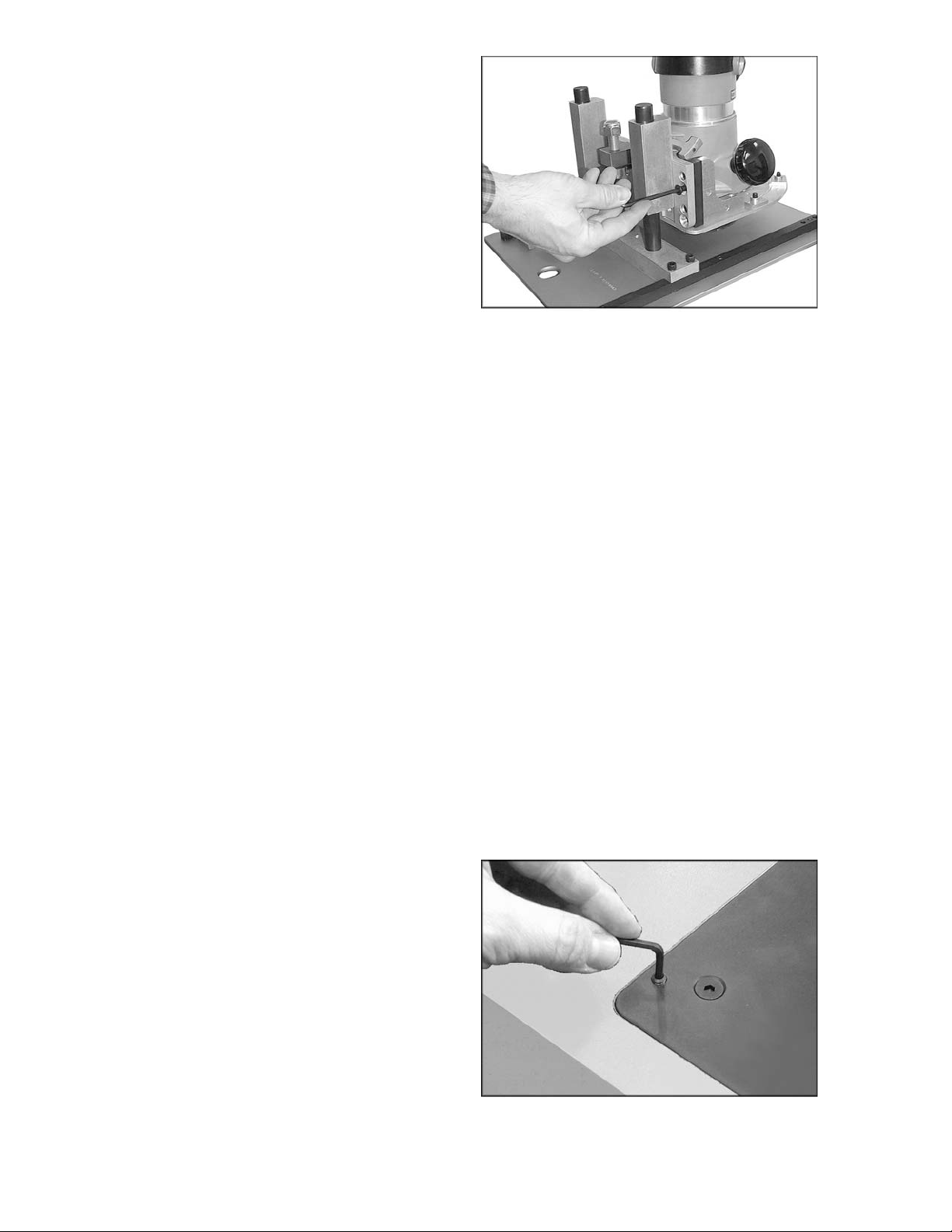
Mounting the Deluxe Fence Assembly
1. Take the three button head Phillips screws
and put one through each hole on the
vertic al side of the aluminum fence support
(Fig. 7). There are thr ee holes on each si de
of the f ence support; do one side at a time.
Start the square nuts on each screw. Do not
tighten, leave loose for installation.
2. Take one fence extension assembly and
install onto the fence support (Fig. 8). The
holes are staggered f or easy installation.
Figure 7
Figure 8
3. Slide assembly along the f ence support unt il
it stops at the fence guard bridge (Fig. 9).
Securely fasten t he screws.
4. Take the remaining three button head
Phillips scre w and perform steps 1, 2 and 3
on the other side of the fence support .
5. Install the 1/4-20 x 1 flat head screws and
square nuts into the holes in the MDF
Subfences, leaving clearance under the
nuts. Mount the S ubfence by sliding the nuts
into the T-Slot of the fence extension (Fig.
10).
Figure 9
Figure 10
7
Page 8

NOTE: The MDF Subfences can be
mounted either on the left or right but the
screws should be closest to the center of
the fence once installed (Fig. 11).
The sub-fence is adj usted by loosening the
two flat head screws on the front of each
MDF board. O nce loosened, slide t he board
to the desired openi ng. Securely tighten t he
flat head screws.
6. Mount the adjustable fence guard to the
bridge on the fence bracket with the two
fence guard knobs (Fig. 12).
Figure 11
7. Mount the assembled fence to the main
plate of the ROUT-R-LIFT with one fence
knob in each of the threaded holes in the
top corners of the plate (Fig. 13).
8. The vacuum attachment is sized to accept
standard 2-1/4" vacuum hose or a dust
collector adaptor (see your local Powermatic
dealer f or adaptors). To install hose on the
vacuum attachment, press nozzle down
slightly on the fl exibl e arms and pivot inward
(Fig. 14).
Figure 12
Figure 13
Figure 14
8
Page 9
Using Your Rout-R-Lift
Always turn router off and
disconnect router from pow er source befo re
making any height adju st ment.
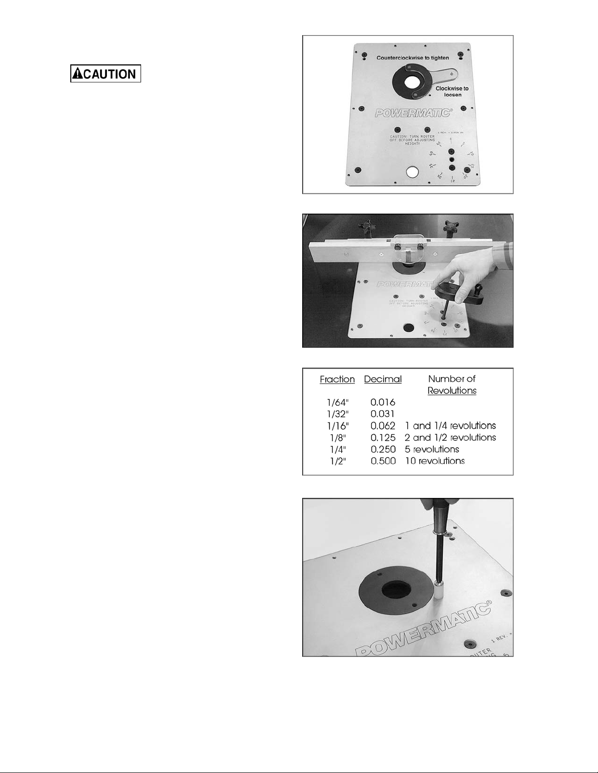
1. Depending on the si ze of the router bit you
are using it may be desirable to use an
insert ri ng to reduc e the siz e of t he opening.
To install the insert ri ng place the insert i nto
the opening of t he main plate, then with the
insert wrench turn counterclockwise to
tighten (then remove the insert wrench).
See Fig. 15.
2. With the router bit installed, place the
adjustment handle into the access port in
the main plat e (Fig. 16).
Figure 15
3. Bring the bit fl ush to the t able top.
4. To raise your router, turn the adjustment
handle clockwise; to lower turn the
adjustment handle counterclockwise. Keep
in mind that one complete revoluti on of the
adjustment handle equals 0.050" or 1/20".
See Fig. 17.
5. Make the desired height adjustment. When
your adjustment is complete, remove the
adjustable handle.
6. A start ing pi n is provi ded to assist i n certai n
freehand operations when the fence is not
used. Thread the pin into the router plate
with a screwdriver (Fig. 18).
Figure 16
Figure 17
Figure 18
9
Page 10
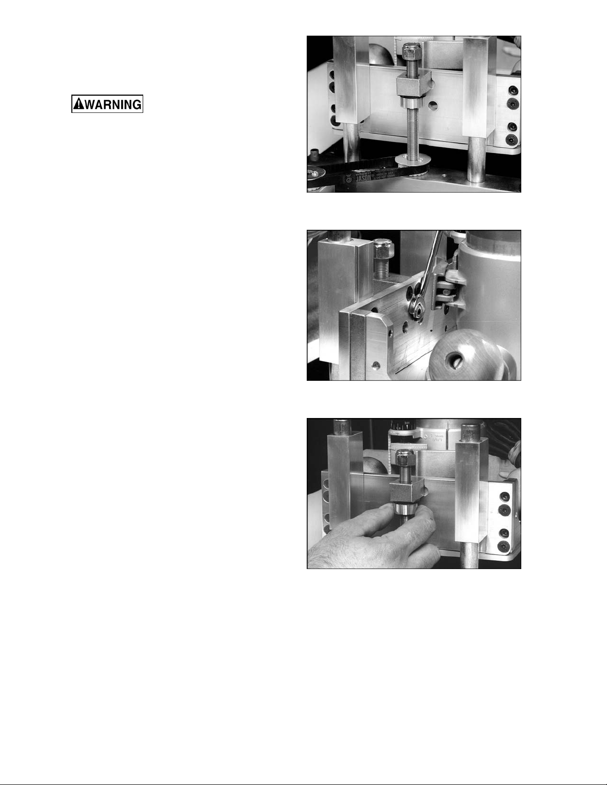
Modification for Height Adjustment Tension
Disconnect router from power
source.
The height adjustm ent tension is set at the
factory; however, if you find the tension is too
loose and the router' s hei ght adjustment moves
when routing, then modification is as follows:
1. Turn your Rout-R-Lift upside down on a
table (Fig. 19) .
2. With a 7/16 open end wrench, loosen the
1/4-20 hex nut (Fi g. 20). Then back out the
set screw with the 1/8 hex wrench.
Figure 19
3. Rotate the brass anti-backlash nut so it
tightens agai nst the rubber washer (Fig. 21).
NOTE: A drop of oil on the rubber washer
eases the rotation of the brass nut against
the washer.
4. Make certain when you have finished
tightening the brass anti-backlash nut that
one of the slots on the nut is centered t o the
set screw. This ensures that the set screw
will protrude into the slot of the antibacklash nut. S ee Fig. 21.
5. Snug the set screw, then ti ghten the 1/4-20
hex nut (that you loosened in step 2) .
Figure 20
Figure 21
Replacement Parts
Replacement par ts listed on t he foll owing pages. T o order par ts or reach o ur servic e department, call 1800-274-6848, Monday through Friday (see our website for business hours, www.powermatic.com).
Having the Model Number and Serial Number of your mac hine available when you cal l will allow us to
serve you quickly and accurately.
10
Page 11

Rout-R-Lift Deluxe Fence Assembly
Index No. Part No . Description Size Qty
................. 6682004F ................Rout-R-Lift Deluxe Fence (Items 1 thru 13) .. ...........................................
1 ............... XLIFT-M0026 ...........Fence Clamping Knobs ............................... ......................................... 2
2 ............... XLIFT-E0040 ...........Button Head Screw ...................................... 1/4-20 x 1/2" ..................... 6
3 ............... PLIFT-E0032 ...........Alum inum Fence Brack et ............................. 2-1 /2 " x 2-1/2" x 3/16" x 14"1
4 ............... XLIFT-M0039 ...........Fence Guard ............................................... 1/8 Polycar bonate ............. 1
5 ............... XLIFT-M0028 ...........Guard Clamping Knob ................................. ......................................... 2
6 ............... PLIFT-E0030 ...........Alum inum Fence Exte n sion ......................... 7 /1 6 " x 2-1/2 " x 7" ............. 2
7 ............... XLIFT-F0028 ............Square Nut .................................................. 1/4-20 ............................. 10
8 ............... XLIFT-M0040 ...........MDF Sub Fe n ce s......................................... 3 /4 " x 2-1/2" x 10-3 /4 " ....... 2
9 ............... XLIFT-F0017 ............Flat Head Screws ........................................ 1/4-20 x 1" ........................ 4
10 ............. XLIFT-E0032A .........Plastic Dust Collector Connector.................. ......................................... 1
11 ............. TS-081A032.............Pan Head Phillips Machine Screw ............... #6-32 x 1/2” ...................... 4
12 ............. PLIFT-E0032B .........Aluminum Safety Guard Bracket .................. ......................................... 1
13 ............. TS-081A012.............Pan Head Phillips Machine Screw ............... #6-32 x 1/4” ...................... 2
11
Page 12

Rout-R-Lift Assembly – Exploded View
12
Page 13

Rout-R-Lift Assembly – Parts List
Index No. Part No . Description Size Qty
1 ............... XLIFT-F0001 ............Flat Head Cap Screw................................... 1/4-20 x 3/4 .................... 28
2 ............... PLIFT-P0003-1 ........Aluminum Main Plate ................................... 1 4 -3 /4 x 11-3 /4 x 1/4 ......... 1
3 ............... XLIFT-S0001-1 ........Steel Side Supports ..................................... 1/2 x 1/2 x 13-1/4 .............. 2
4 ............... XLIFT-E0001-1 ........Aluminum Shaft Mounting Block .................. 1 x 1-1/2 x 10.1 ................. 1
5 ............... XLIFT-F0002 ............Socket Head Cap Screw .............................. 1/4-20 x 7/8 ...................... 4
6 ............... XLIFT-M0001 ...........Steel Drive Pulley Spindle ............................ ......................................... 1
7 ............... XLIFT-M0006 ...........Bronze Flange Bearing ................................ 3/4 x 7/8 x 3/4 ................... 1
8 ............... XLIFT-E0001-2 ........Drive Pulley Mounting Block ........................ 1 x 1-1/2 x 2 ...................... 1
9 ............... XLIFT-M0011 ...........Rubber Timing Belt ...................................... 130 XL x 3/8 ..................... 1
10 ............. XLIFT-M0005 ...........Drive Pulley (Delrin) ..................................... 20 XL x 3/8 ....................... 1
11 ............. XLIFT-M0009 ...........Bronze Sleeve B e a rin g ................................ 3/4 x 7/8 x 3/4 ................... 4
12 ............. XLIFT-F0005 ............Flat Head Cap Screw................................... 1/4-20 x 1 ......................... 4
13 ............. XLIFT-E0001-3 ........Aluminum Bearing Mounts ........................... 1 x 1-1/2 x 4 ...................... 2
14 ............. XLIFT-S0002-1 ........Steel Carriage Nut ....................................... 3 /4 x 1 x 1-1/2 ................... 1
15 ............. XLIFT-F0003 ............Nylon Insert Lock Nut .................................. 1/2-20 ............................... 1
16 ............. XLIFT-E0002-1 ........Aluminum Carriage Bracket ......................... 3/8 x 3 x 8-1/2 ................... 1
17 ............. XLIFT-F0006 ............Half Dog Pt. Set Screw (Anti-Backlash)........ 1/4-20 x 1 ......................... 1
18 ............. XLIFT-M0012 ...........Rubber Washer ........................................... 1/2 x 1-1/16 x .093 ............ 1
19 ............. XLIFT-M0003 ...........Brass Anti-Backlash Nut .............................. 1 x .450 x 1/2-20 ............... 1
20 ............. XLIFT-M0004 ...........Threaded Pulley ( Delri n) .............................. 20 XL w/ 1/2-20 ................ 1
21 ............. XLIFT-F
22 ............. XLIFT-S0001-2 ........Carriage Mounting Block.............................. 1/2 x 1/2 x 3 Steel ............. 2
23 ............. XLIFT-E0002-2 ........Aluminum Carriage Gusset .......................... 3/8 x 2-1/2 x 3 ................... 2
24 ............. XLIFT-P0002 ...........Aluminum Carriage Plate ............................. 7.9 x 8-1/2 x 3/16 .............. 1
25 ............. XLIFT-M0007 ...........Bronze Thrus t Was her ................................. 9/16 x 1-1/4 x 1/1 6 th k ...... 1
26 ............. XLIFT-M0042 ...........Carriage Lead Screw ................................... ......................................... 1
27 ............. XLIFT-M0008 ...........Bronze Flange Bearing ................................ 1/2 x 5/8 x 3/4 Lg .............. 1
28 ............. XLIFT-M0017-1 ........Phenoli c Insert Ring .................................... 1-1/2 hole opening ............ 1
29 ............. XLIFT-M0016-1 ........Insert Wrench .............................................. ......................................... 1
30 ............. XLIFT-M0018 ...........Lift Handle (Arboron) ................................... ......................................... 1
31 ............. XLIFT-M0015 ...........Hex Key ...................................................... 1 /4 .................................... 1
32 ............. XLIFT-F0007 ............Socket Head Cap Screw .............................. 1/4-20 x 1-1/4 ................... 1
33 ............. XLIFT-M0041-1 ........Phenoli c Lift Handle Knob ............................ 1/4" Cored Hole ................ 1
34 ............. XLIFT-P0009 ...........Master Ring ................................................. ......................................... 1
35 ............. XLIFT-P0011 ...........Master Ring Clamp ...................................... ......................................... 6
36 ............. XLIFT-F0008 ............Oval Point Socket Set Screw ....................... 1/4-28 x 1/4 .................... 10
37 ............. XLIFT-P0012 ...........Star ter Pin ................................................... ......................................... 1
0004 ............Socket Head Cap Screw .............................. 1/4-20 x 1 ......................... 4
13
Page 14
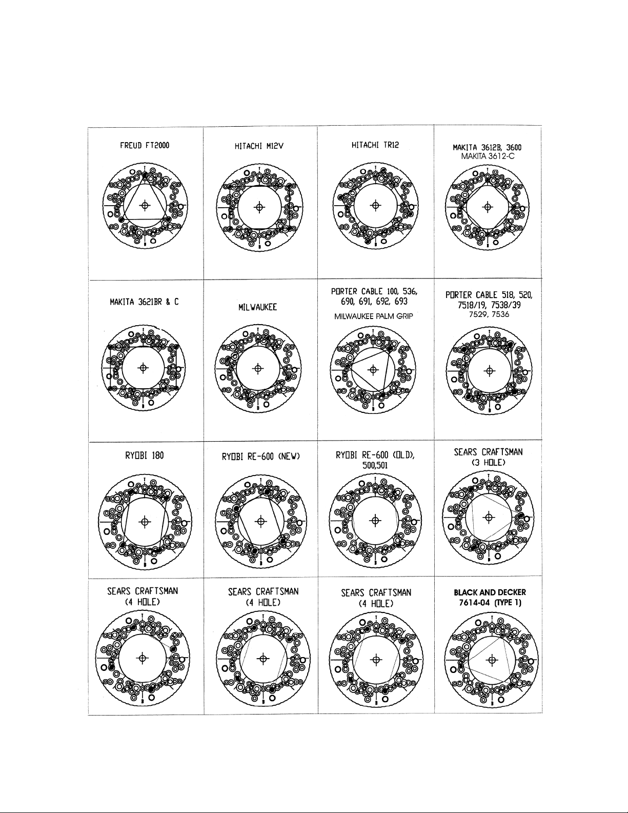
Router Hole Patterns
The following is a series of hol e patt er ns for various router s as not ed in Step 5 of "Mount ing Your Router."
Locate the nam e and correct model number of your router and then l ocate the holes i n the master ring.
With a felt tip m arker or pencil mark a line on the master ring for each hol e you will be using f or your
router.
14
Page 15

Router Hole Patterns (continued)
Making a Cut-out for the Rout-R-Lift
Extension tables are available from Powermatic that mount to a table saw and contain an opening
designed specif ically for the Rout - R- Lift. If you wish to make your own opening in a tabl e, t ur n the Rout -RLift plat e over, and use it as a templ ate to draw the lines for the cutout . Be sure to rout a rec ess 3/8”
deep, or slightly deeper.
15
Page 16

427 New Sanford Rd.
LaVergne, TN 37086
Phone: 800-274-6848
www.powermatic.com
16
 Loading...