

Page 1

This .pdf document is bookmarked
Operating Instructions and Parts Manual
14” Woodworking Band Saw
Model PWBS-14CS
Powermatic
427 New Sanford Rd.
LaVergne, TN 37086 Part No. M-1791216
Ph.: 800-274-6848 Revision F1 01/2014
www.powermatic.com Copyright © 2014 Powerm atic
Page 2

Warranty and Service
Powermatic warrants every product it sells against manufacturers’ defects. If one of our tools needs service or repair,
please contact Technical Service by calling 1-800-274-6846, 8AM to 5PM CST, Monday through Friday.
Warranty Period
The general warranty lasts for the time period specified in the literature included with your product or on the official
Powermatic branded website.
• Powermatic products carry a limited warranty which varies in duration based upon the product. (See chart
below)
• Accessories carry a limited warranty of one year from the date of receipt.
• Consumable items are defined as expendable parts or accessories expected to become inoperable within a
reasonable amount of use and are covered by a 90 day limited warranty against manufacturer’s defects.
Who is Covered
This warranty covers only the initial purchaser of the product from the date of delivery.
What is Co vered
This warranty covers any defects in workmanship or materials subject to the limitations stated below. This warranty
does not cover failures due directly or indirectly to misuse, abuse, negligence or accidents, normal wear-and-tear,
improper repair, alterations or lack of maintenance.
Warranty Limitations
Woodworking products with a Five Year Warranty that are used for commercial or industrial purposes default to a
Two Year Warranty. Please contact Technical Service at 1-800-274-6846 for further clarification.
How to Get Technical Support
Please contact Technical Service by calling 1-800-274-6846. Please note that you will be asked to provi de proof
of initia l p u rch a s e whe n calling. If a product requires further inspection, the Technical Service representative will
explain and assist with any additional action needed. Powermatic has Authorized Service Centers located throughout
the United States. For the name of an Authorized Service Center in your area call 1-800-274-6846 or use the Service
Center Locator on the Powermatic website.
More Information
Powermatic is constantly adding new products. For complete, up-to-date product information, check with your local
distributor or visit the Powermatic website.
How S tat e Law A pplies
This warranty gives you specific legal rights, subject to applicable state law.
Limitations on This Warranty
POWERMATIC LIMITS ALL IMPLIED WARRANTIES TO THE PERIOD OF THE LIMITED WARRANTY FOR EACH
PRODUCT. EXCEPT AS STATED HEREIN, ANY IMPLIED WARRANTIES OF MERCHANTABILITY AND FITNESS
FOR A PARTICULAR PURPOSE ARE EXCLUDED. SOME STATES DO NOT ALLOW LIMITATIONS ON HOW
LONG AN IMPLIED WARRANTY LASTS, SO THE ABOVE LIMITATION MAY NOT APPLY TO YOU.
POWERMATIC SHALL IN NO EVENT BE LIABLE FOR DEATH, INJURIES TO PERSONS OR PROPERTY, OR
FOR INCIDENTAL, CONTINGENT, SPECIAL, OR CONSEQUENTIAL DAMAGES ARISING FROM THE USE OF
OUR PRODUCTS. SOME STATES DO NOT ALLOW THE EXCLUSION OR LIMITATION OF INCIDENTAL OR
CONSEQUENTIAL DAMAGES, SO THE ABOVE LIMITATION OR EXCLUSION MAY NOT APPLY TO YOU.
Powermatic sells through distributors only. The specifications listed in Powermatic printed materials and on the official
Powermatic website are given as general information and are not binding. Powermatic reserves the right to effect at
any time, without prior notice, those alterations to parts, fittings, and accessory equipment which they may deem
necessary for any reason whatsoever.
Product Listing with Warranty Period
90 Days – Parts; Consumable items
1 Year – Woodworking Machinery used for industrial or commercial purposes
5 Year – Woodworking Machinery
NOTE: Powermatic is a division of JPW Industries, Inc. References in this document to Powermatic also apply to
JPW Industries, Inc., or any of its successors in interest to the Powermatic brand.
2
Page 3

Table of Contents
Warranty and Servic e .............................................................................................................................. 2
Table of Contents .................................................................................................................................... 3
Warning ................................................................................................................................................... 5
Introduction ............................................................................................................................................. 6
Features and Specifications ..................................................................................................................... 7
Grounding Inst r uc tions ............................................................................................................................. 8
115 Volt Operati on ............................................................................................................................... 8
230 Volt Operati on ............................................................................................................................... 8
Extension Cords................................................................................................................................... 9
Unpac king ............................................................................................................................................. 10
Contents of the Shipping Container .................................................................................................... 10
Installation and Assembly ...................................................................................................................... 12
Mounting Band Saw to Stand ............................................................................................................. 12
Installing Drive Belt ............................................................................................................................ 13
Installing Trunnion Support................................................................................................................. 14
Installing Extension Table .................................................................................................................. 14
Installing Main Table .......................................................................................................................... 14
Leveling the Extension Table ............................................................................................................. 15
Installing Rear Rail ............................................................................................................................. 15
Installing Fr ont Rail and Rip Fence ..................................................................................................... 16
Resaw Guide ..................................................................................................................................... 18
Blower Nozzle .................................................................................................................................... 18
Work Lamp ........................................................................................................................................ 18
Installing Quick Tension Lever............................................................................................................ 19
Stand Attachments ............................................................................................................................. 19
Dust Collection ................................................................................................................................... 19
Riser Block Accessory........................................................................................................................ 19
Adjustments ................................................................................................................... ....................... 2 0
Tilting th e Table ............................................................................................................. .................... 2 0
Adjusting 90° Table Stop .................................................................................................................... 20
Table Aligned wit h Bl ade .................................................................................................................... 21
Installing Blades ................................................................................................................................. 21
Blade Tension .................................................................................................................................... 22
Blade Tracking ................................................................................................................................... 23
Guide Post and Upper Bl ade Guard ................................................................................................... 23
Upper Bearing G uides ........................................................................................................................ 24
Lower Bearing Guides ........................................................................................................................ 24
Miter Gauge ....................................................................................................................................... 25
On/Off Switch ..................................................................................................................................... 2 6
Maintenance .......................................................................................................................................... 26
Blade Selecti on ..................................................................................................................................... 27
Width ................................................................................................................................................. 27
Pitch ......................................................................................................................... ......................... 27
Shape ................................................................................................................................................ 27
Set ..................................................................................................................................................... 28
Material .............................................................................................................................................. 28
Blade Breakage ................................................................................................................................. 28
Operation .............................................................................................................................................. 2 9
General Procedure ............................................................................................................................. 29
Ripping .............................................................................................................................................. 29
Crosscutting ....................................................................................................................................... 29
Resawing ........................................................................................................................................... 30
Blade Lead ........................................................................................................................................ 30
Troubleshooting – Mechanical and Elect ri c al P r oblem s .......................................................................... 31
Troubleshooting – Operating Problems .................................................................................................. 32
Optional Accessories ............................................................................................................................. 34
Blade Selecti on Guide ........................................................................................................................... 35
For Radius Cutti ng ............................................................................................................................. 35
3
Page 4

Replacement Parts ................................................................................................................................ 36
Parts List: Body Assembly .................................................................................................................. 3 6
Body Assembly .................................................................................................................................. 39
Parts List: Closed St and A ssembly ..................................................................................................... 40
Closed Stand Assembl y ..................................................................................................................... 41
Parts List: Fence and Rail Assembly .................................................................................................. 4 2
Fence and Rail Assembly ................................................................................................................... 43
Parts List: Table and Trunnion Assembly............................................................................................ 44
Parts List: Miter Gauge Assembly....................................................................................................... 45
Parts List: Bl ade Tension Lever .......................................................................................................... 46
Electri c al Connec tions for PWBS-14CS ................................................................................................. 47
4
Page 5

Warning
1. Read and understand this entire owner’s manual before attempting assembly or operation.
2. Read and understand the warnings po sted on the m achine and i n thi s manual. Fail ure to comply wit h
all of these warnings m ay cause seriou s i njury.
3. Replace the warning labels if they become obscured or remov ed.
4. This band saw is designed and i ntended for use by pr operl y tr ained and ex peri enced personnel only .
If you are not familiar with the proper and safe operation of a band saw, do not use until proper
training and knowledge have been obtained.
5. Do not use this band saw for other than its intended use. If used for other purposes, Powermatic
disclaim s any real or i mplied warrant y and h olds itsel f harml ess from any injury t hat may r esult f rom
that use.
6. Always wear approved saf ety gl asses/face shi elds whil e using this ba nd saw. (Ev eryday ey eglasses
only have impact resi stant lenses; they are not saf ety glasses.)
7. Before operating the band saw, r emove ti e, rings, watches and other jewel r y , and roll sl eeves up past
the elbows. Remove all loose clothing and confine long hair. Non- sl ip footwear or anti-ski d floor strips
are recommended. Do not wear gloves.
8. Wear ear protector s (plugs or muffs) during extended periods of operati on.
9. Some dust created by power sanding, sawing, grinding, drilling and other construction activities
contains chemicals known to cause cancer, birth defects or other r epr oduc tive harm. Some exam ples
of these chemic als are:
• Lead from lead based paint.
• Crystalli ne sil ic a from bricks, cement and other m asonry pr oduc ts.
• Arsenic and chromium from chemically treated lum ber .
Your risk of exposure varies, depending on how often you do this type of work. To reduce your
exposure to these chemicals, work in a well-ventilated area and work with approved safety
equipment, such as face or dust masks that are specifically designed to filter out microscopic
particles.
10. Do not operate this machine while tired or under the influence of drugs, alcohol or any m edic ation.
11. Make certain t he switc h is i n the OFF position before connect ing the machine to the power supply .
12. Make certain t he machine is properly grounded.
13. Make all machine adjustments or maintenance with the machine unplugged from the power source.
14. Remove adjusting keys and wrenches. Form a habit of checking to see that keys and adjusting
wrenches are removed from the machine before turning it on.
15. Keep safety guards in place at all times when the machine is in use. If removed for maintenance
purposes, use extreme caution and replac e the guards immediately.
16. Make sure the band saw is firmly secured to the stand or a work bench befor e use.
17. Check damaged parts. Before further use of the machine, a guard or other part that is damaged
should be carefully checked to determine that it will operate properly and perform its intended
function. Chec k for alignment of moving par ts, binding of moving parts, breakage of parts, mounting
and any other condi ti ons that m ay affect its operati on. A guard or ot her part that i s damaged should
be properly repaired or replaced.
18. Provide f or adequate space surrounding work area and non- glare, overhead lighting.
19. Keep the floor around the machine clean and free of scrap material, oil and grease.
20. Keep visit or s a safe di stanc e from the work area. Keep children away.
21. Make your workshop chil d pr oof with padlocks, master switc hes or by r emoving starter key s.
5
Page 6

22. Make your workshop chil d pr oof with padlocks, master switc hes or by r emoving starter key s.
23. Giv e your work undivi ded attention. Looki ng around, carryi ng on a conversati on and “horse-play” ar e
careless acts that can r esul t in serious injury.
24. Maintain a balanced stance at all times so that you do not f all or lean against the blade or other
moving part s. Do not over r eac h or use excessive force to perform any m ac hine oper ation.
25. Use the ri ght t ool at the cor rect speed and f eed rate. Do not for ce a t ool or attachm ent to do a j ob for
which it was not designed. T he ri ght tool will do the job better and safer.
26. Make relief cut s where possibl e, when cutting curved stock.
27. W hen feeding sm all work piece s into the bl ade, al ways use a pus h stic k, fix ture, or simil ar devi ce to
keep hands at a safe distanc e.
28. Use recommended accessories; improper accessories may be hazardous.
29. Do not expose machine t o rai n or use in wet or dam p locations.
30. Mai ntain tools with care. Keep bl ades sharp and clean for the best and saf est performance. Follow
instructions for lubricating m ac hine and c hanging accessories.
31. Turn of f the m achine and discon nect f rom power bef ore cleani ng. Use a bru sh or com pressed air to
remove chips or debris — do not use your hands.
32. Do not stand on the machine. S eri ous i njur y c oul d oc c ur if the mac hine tips over.
33. Never leave t he m ac hine r unning unattended. Turn the power off and do not l eav e the mac hine until it
comes to a complete stop.
34. Remove loose it em s and unnecessary work pieces from the ar ea before starting the machine.
Familiariz e you rself with the following safet y no tices used in this manual:
This means that if precautions are not heeded, it may result in minor injury and/or
possible machine damage.
This means that if precautions are not heeded, it may result in serious and possibly fat al
injury.
Introduction
This manual is provided by Powermati c covering the safe operat ion and maintenance pr ocedures for a
Powermatic Model PWBS-14CS Band Saw. This manual contains instructions on installation, safety
precautions, gener al oper ati ng procedur es, mai ntenance i nstructi ons and parts breakdo wn. Thi s mac hine
has been designed and con structed t o provide year s of troubl e free operation if used in accordanc e with
instructi ons set forth i n this manual . If there are any questions or comm ents, please contact either your
local supplier or Powermatic. Powermatic can also be reached at our web site: www. powermatic.com.
The specifi cati ons in thi s m anual were cur rent at the t i m e this m anual was publi shed, but b ecau se of our
policy of c ontinuous improvement, Powermatic reserves the right to change specifications at any time and
without pri or notic e, without incurri ng obligations.
6
Page 7
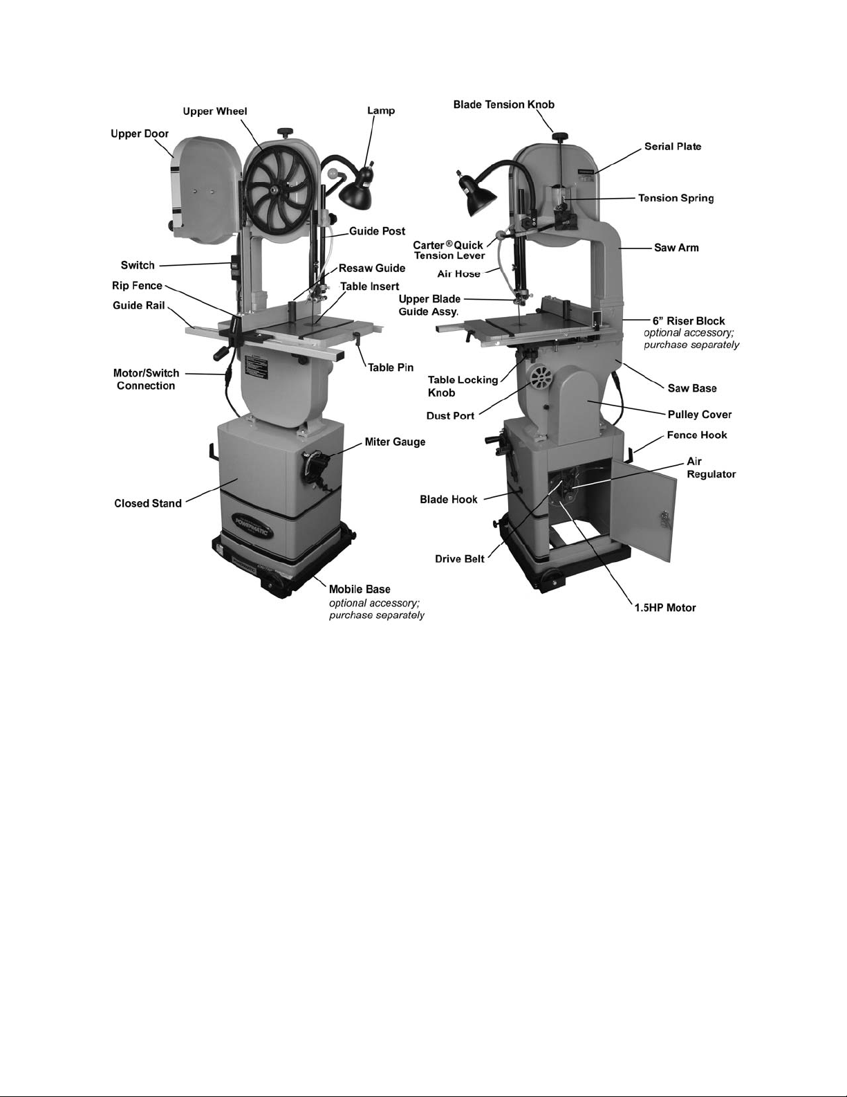
Features and Specifications
Figure 1
Model Number ....................................................................................................................... PWBS-14CS
Stock Num ber............................................................................................................................ 1791216K
Resaw (Height) Capacity (in.) .................................................................................................................. 6
Cutting Widt h (Thr oat Capacity)(in.) ................................................................................................. 13-1/2
Minimum Saw Blade Width (in.) ............................................................................................................ 1 /8
Maximum Saw Blade Wi dth (in.) ........................................................................................................... 3/4
Blade Length (in.) ............................................................................................................................ 93-1/2
Main Table Size (Lx W)( in .) ............................................................................................................. 15 x 15
Extension Table Size (LxW)(in.) .................................................................................................. 15 x 5-1/2
Blade Speed (SFPM ) ......................................................................................................................... 3000
Table Tilt (deg.) ................................................................................................................45 Right, 10 Left
Table He ight from Floo r (in .) .................................................................................................................. 44
Dust Chute Outside Diameter (in.) ........................................................................................................... 4
Minimum Dust Coll ecti on CFM Required .............................................................................................. 350
Motor ......................................................... TEFC, 1.5HP, 1PH, 115/230V (prewired 115V ) , 11/5.5A, 60Hz
Recommended cir c uit
Overall Dim ensi ons – Body and Stand fully assembled (LxWxH) (in.)....................................... 20 x 34 x 68
Stand Footpri nt (LxW)(in.) ......................................................................................................... 16 x 17-1/2
Approximate Weights:
Body (Net/Shipping)(lbs.) ......................................................................................................... 166/178
Closed Stand (Net/Shipping) (l bs.) ................................................................................................ 84/88
(*subject to local electrical codes) ............................................. 30A (115V ) , 20A (230V)
7
Page 8

Grounding Instructions
This tool must be grounded while in use to protect the operator from electric
shock.
In the event of a malfunction or breakdown, groundi ng provides a path of least resistance f or electric
current to reduce the risk of electric shock. This tool is equipped with an electric cord having an
equipment-gr ounding conductor and a groundi ng plug. The pl ug must be plugged into a matc hing outlet
that is properly installed and grounded in acc or danc e with all local codes and ordinances.
Do not modify the plug provided. If it will not fit the outl et, have the proper outl et installed by a qualif ied
electrician.
Improper connection of the equipment-grounding conductor can result in a risk of electric shock. The
conductor, with insulation having an outer surface that is green with or without yellow stripes, is the
equipment-gr ounding conduct or. If repai r or replacem ent of the electri c cord or plug i s necessary, do not
connect the equipment-grounding conduc tor to a live terminal.
Check with a qualified electrician or servi ce personnel if the grounding instructions are not completely
understood, or if in doubt as to whether t he tool is properly gr ounded. Use only three wire ex tension cords
that have thr ee- pr ong gr ounding plugs and three-pole recept ac les that accept the tool’s plug.
Repair or replace a dam aged or worn cord im mediately.
It is recommended that the PWBS-14CS Band Saw, when operated at 115 volts, be connected to a
grounded and dedi cated 30 amp ci rcuit with circuit breaker or time delay f use. When oper ated at 230
volts, c onnect t he saw to a 20 am p dedi cat ed ci rc uit with breaker or tim e del ay f use. Lo cal co d es take
precedence o ver recommendations.
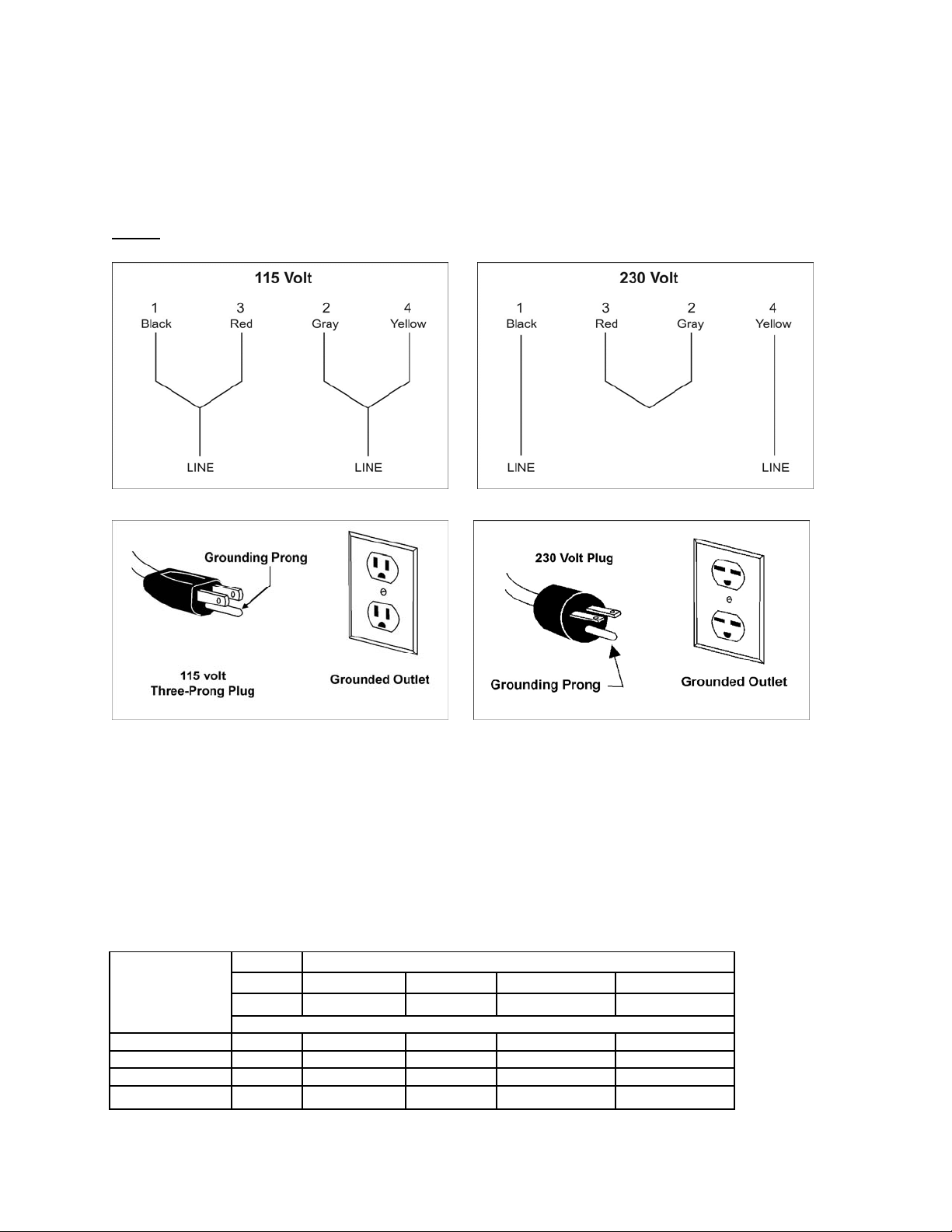
115 Volt Operation
As received fr om the factory, your band saw is wired to run at 115 volt oper ation. This band saw, when
wired for 115 volts, is i ntended for use on a circuit that has an outlet and a plug that looks like the one
illustrated in Figure 2. A temporary adapter, which looks like the adapter illustrated in Figure 3, m ay be
used to connect this plug to a two-pole receptacle, as shown in Figure 3 if a properly grounded out let is
not available. The temporary adapter should only be used until a properly gr ounded outlet can be
install ed by a qualif ied electrician. This adapter is not applicable in Canada. The green colored ri gid
ear, lug, or tab, extending from the adapter, m ust be connected to a permanent gr ound such as a
properly grounded outlet box, as shown in Figur e 3.
Figure 2 Figure 3
230 Volt Operation
If 230V, singl e- phase operat ion is desired, the f ollowing instructions must be followed:
Disconnect the mach in e f rom the power sou rce.
This band saw is supplied with four motor leads that are connected for 115V operation, as shown in
Figure 4. Reconnect these four motor leads for 230V operation, as shown in Figure 5. These diagrams
are also found insi de the cover of the motor junction box.
8
Page 9
The 115V attachment plug (shown in Figure 6) supplied with the band saw, must be replaced with a
A
UL/CSA listed pl ug suit able f or 230V oper ati on (s hown i n F igur e 7). Cont act your l ocal aut hori zed Walt er
Meier (Manuf acturi ng) Inc., serv ic e center or qualifi ed elec trici an for pr oper proc edures to i nstall the pl ug.
The band saw must comply with all local and national codes after the 230 volt plug is installed.
The band saw with a 230 v olt pl ug should only be connec ted to an o utlet having t he same confi gurati on
(see Figure 7). No adapter is available or should be used with the 230 volt plug.
Important: In all cases (115 or 230 vol t s) , make certain the receptacl e in quest io n i s properly
grounded. If you are not su re, h ave a regi st ered el ectri cian check the recept acle.
NOTE: The lamp is designed fo r use wi th 115V power. I f the saw i s converted to 230V, discontinue
use of the lamp, and use an alt ernate lamp with an independent electrical source.
Figure 4 Figur e 5
Figure 6 Figure 7
Extens ion Cords
If an ext ension cord is necessary, make sure the cord r ating is suitabl e for the amperage l isted on the
machine’s mot or plat e. An undersized c ord will cause a drop i n line v oltage r esulting in loss of power and
overheating.
Use the chart in Figure 8 as a general guide in choosing the correc t size extension c or d for the band saw.
If in doubt, use the next heav ier gauge. The smaller the gauge number, the heavier the cord.
Recommended Minimum Gauge (AWG) of Extension Cords
Volts Total Length of Cord in Feet
115 V 25 ft. 50 ft. 100 ft. 150 ft.
230 V 50 ft. 100 ft. 200 ft. 300 ft.
Ampere Rating
< 6 18 16 16 14
6 to 10 18 16 14 12
10 to 12 16 16 14 12
12 to 16 14 12 Not recommended Not recommended
WG
Figure 8
9
Page 10
Unpacking
The band saw is shipped i n two cartons. Open
both cartons and inspect contents for shipping
damage. Report any damage immediately to
your distributor and shipping agent. Do not
discard any shipping material until the Band
Saw is assembled and running properly.
Compare the contents of both cartons and all
internal boxes with the following parts list to
make sure all parts are intact.(*) Missing parts, if
any, should be report ed to your distributor. Read
this instruc tion manual thoroughl y for assembly,
maintenance and safety instructions.
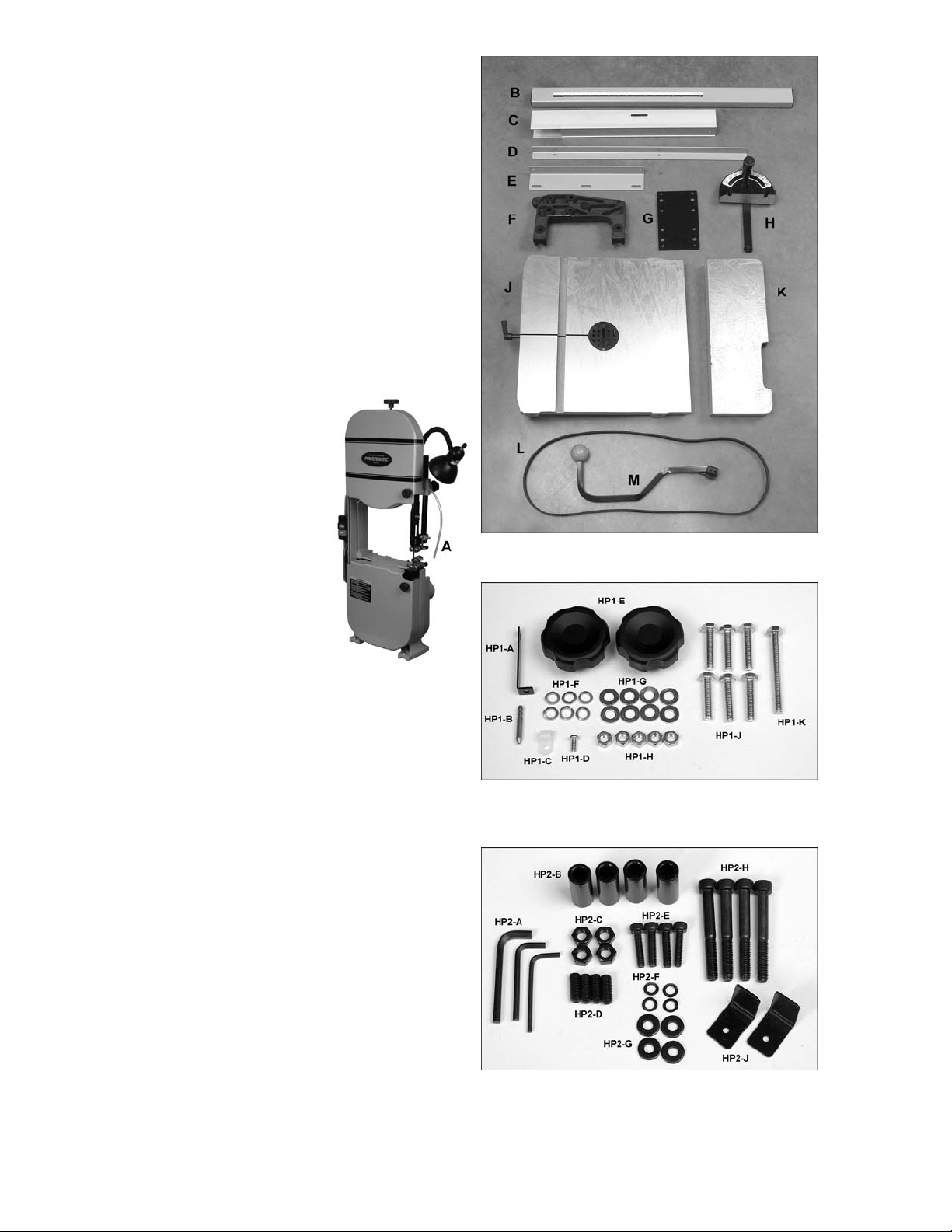
Contents of the Shipping Conta iner
Carton #1 – Band Saw:
Refer to Figure 9.
1 Band Saw – (A)
1 guide rail – (B)
1 rip fence – (C)
1 rear rail – (D)
1 front rail – (E)
1 trunnion support – ( F)
1 level board – (G)
1 miter gauge – (H)
1 main table – (J)
1 extension table – (K)
1 drive belt – (L)
1 quick tension l ev er – (M)
1 owner's manual ( not shown)
1 warranty card (not sho wn)
2 Hardware packages, as follows.
Hardware Package #1 cont ains:
Refer to Figure 10.
1 support plate (HP1-A)
1 air jet nozzle (HP1-B)
1 cord clamp (HP1-C)
1 pan head screw, M5x12 (HP1-D)
2 table locking knobs (HP1-E )
6 lock washers, M8 (HP1-F)
8 flat washers, M8 (HP1-G)
5 hex nuts, M8 (HP1-H)
6 hex cap screws, M8x40 (HP1-J)
1 hex cap screw, M8x80 (HP1-K)
Hardware package #2 contains:
Refer to Figure 11.
3 hex (Allen) wrenches, 3,4, 5mm (HP2-A)
4 spacers (HP2-B)
4 hex nuts, M8 (HP2-C)
4 socket set screws, M8x20 (HP2-D)
4 socket head cap screws, M6x25 (HP 2-E)
4 lock washers, M6 (HP2-F)
4 flat washers, M6 (HP2-G)
4 socket head cap screws, M8x65 (HP 2- H )
2 L-spacers (HP2-J)
Figure 9
Band Saw carton
Figure 10
Hardware package #1
(stock no. PWBS14- HP 1)
Figure 11
Hardware package #2
(stock no. PWBS14- HP 2)
10
Page 11
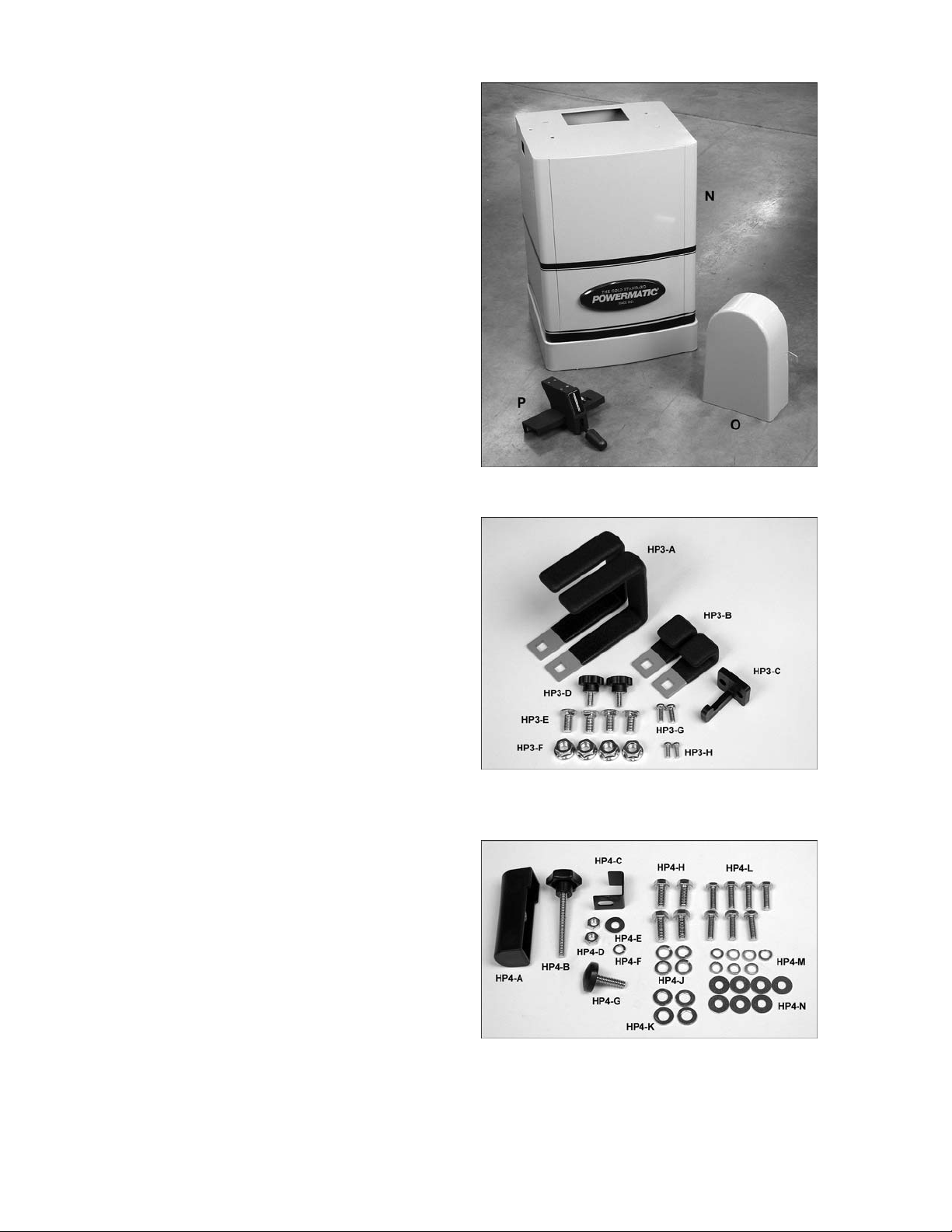
Carton #
2
- Stand:
Refer to Figure 12.
1 Stand with mot or (N)
1 pulley cover (O)
1 fence body (P)
2 hardware packages, as follows.
Hardware package #3 contains:
Refer to Figure 13.
2 fence hooks (HP3-A)
2 miter gauge hooks (HP3-B)
1 blade hook (HP3-C)
2 pulley cover knobs (HP3-D)
4 carriage bolts, M8x 16 (HP3-E )
4 flanged hex nuts, M8 (HP3-F)
2 pan head screws, M5x12 (HP3-G)
2 pan head screws, M4x10 (HP3-H)
Hardware package #4 contains:
Refer to Figure 14.
1 resaw pin (HP4-A)
1 resaw pin knob (HP4-B)
1 fence rear hook (HP4-C)
2 hex nuts, 1/4” (HP4-D)
1 flat washer, 1/4” (HP4-E)
1 lock washer, 1/4” (HP4-F)
1 sliding pad (HP4-G)
4 hex cap screws, 5/16”x3/4” (HP4-H)
4 lock washers, 5/16” (HP4- J)
4 flat washers, 5/16” (HP4-K )
7 hex cap screws, M6x20 (HP4-L)
7 lock washers, 1/4” (HP4-M)
7 flat washers, 1/4” (HP4-N)
(*) the identifying letters/numbers in parentheses are
used throughout the text to clarify assembl y. For
actual part numbers if re-ordering, see the part
breakdowns at the back of this manual.
Figure 12
Stand carton
Figure 13
Hardware package #3
(stock no. PWBS14- HP 3)
Figure 14
Hardware package #4
(stock no. PWBS14- HP )
11
Page 12
Installation and Assembly
Tools required for assembly:
open-end or box wrenches– 10mm , 12mm, 1/2”
[in some c ases, a socket wrench set can be
used to speed assembly time]
hex (Allen) wrenches – 3, 5, 6mm
Cross point (Phillips) screwdriver
square
straightedge
NOTE: If further clarification is needed for any of
the following assembly procedures, consult the
exploded views at the bac k of t his manual.
Exposed met al surf aces on the Ban d Sa w, such
as the table, have been given a protective
coating at the factory. This should be removed
with a soft cl oth moistened with a l ight solvent.
Do not use gasoline, lacquer thinner, acetone,
or other highl y volatile solvents f or this. Do not
use an abrasive pad as it may scratch the
polished metal surfaces.
IMPORTANT: The Band Saw must be
disconnect ed from the power source bef ore
any assembly procedu res!
Mounting Band Saw to Stand
Refer to Figures 15 and 16.
1. Remove loose items from inside of stand.
2. Place stand upright on a level surface. If
desired, the stand can be f urther stabilized
by securing it to the floor with lag screws
through the inside corner holes. If using a
mobile base, lock the casters before
assembling or oper ating the band saw.
T he saw body is heavy – u se
caution when l ifting, and stab iliz e until fi rmly
attached to the stand . Failure to co mply may
cause serious inj ury.
3. With the aid of a second person, lift the
Band Saw out of t he shipping cont ainer and
place on top of the stand. Make sure that
front of saw (with Powermatic nameplate)
faces same direction as curved stand front.
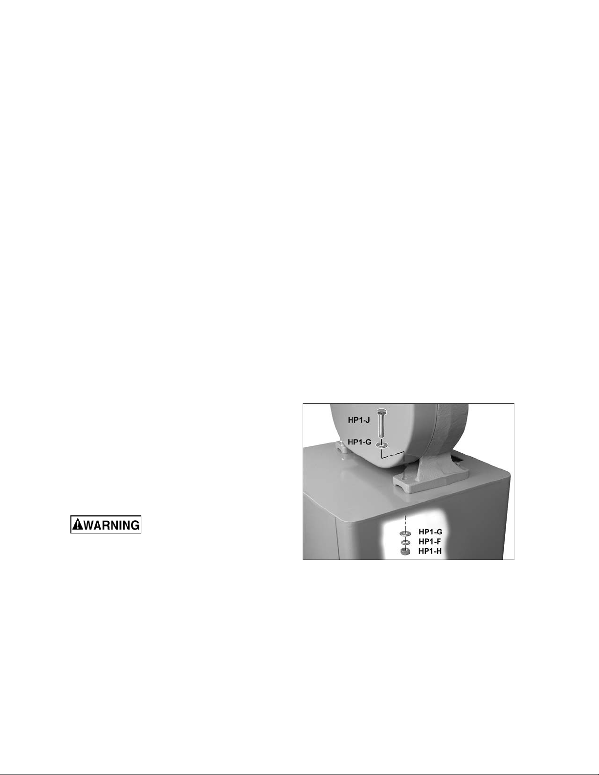
4. Line up holes in t he saw base wit h holes in
the top of the st and. F asten saw base to the
stand with four M8x40 hex cap screws
(HP1-J), eight M8 flat washers (HP1-G) , four
M8 lock washers (HP1-F), and f our M8 hex
nuts (HP1-H). Use a 1/2” wrench to tighten.
Figure 15
12
Page 13
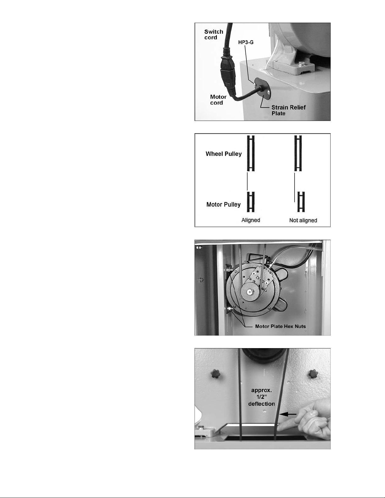
5. Push motor cord and strain relief plate
through the opening to the outside of the
stand, as shown in Figure 16. Fasten the
strain relief plate to the stand with two
M5x12 pan head screw s (HP3-G) .
6. Connect the plugs of the switch cord and
motor cord (Figure 16). Do not connect
machine to power source during
assembly.
Installing Drive Belt
Refer to Figures 17 t hr ough 20.
1. The motor and wheel pulleys have been
accurately aligned with each other by the
manufacturer. However, the user may wish
to verify this setting in case misalignment
has occurred during transit. Misaligned
pulleys can produce excessive wear on
drive belts.
2. If the pulleys do not lie in a straight plane
(Figure 17) , loosen the set scre w on one of
the pulley s and shif t the pul l ey in or out until
both pulleys lie in a straight plane. Tighten
set sc rew.
3. Open the lower door, and loosen the four
hex nuts on the motor plate an equal
amount, with a 1/ 2” wrench (see Figur e 18).
Lift up on t he motor to provi de slack for t he
drive belt installation.
4. Install t he belt around the mot or pulley and
the wheel pull ey.
5. Tension the drive belt by pushing down on
the motor. You may have to push down
harder on the pulley end of the motor to
overcome t he pressure of the driv e belt and
keep the motor pulley aligned wit h the wheel
pulle y.
6. Tighten the f our hex nut s on the m otor plate.
NOTE: The belt is properly tensioned when
finger pressure between the two pulleys
causes approximately 1/2” def lection (Fi gure
19).
Figure 16
Figure 17
Figure 18
7. Screw the two pulley cover knobs (HP3-D)
into the threaded holes in the back of the
saw, as shown in Fi gure 20. Sli de the pull ey
cover down ov er the knobs, and ti ghten the
knobs.
Figure 19
13
Page 14
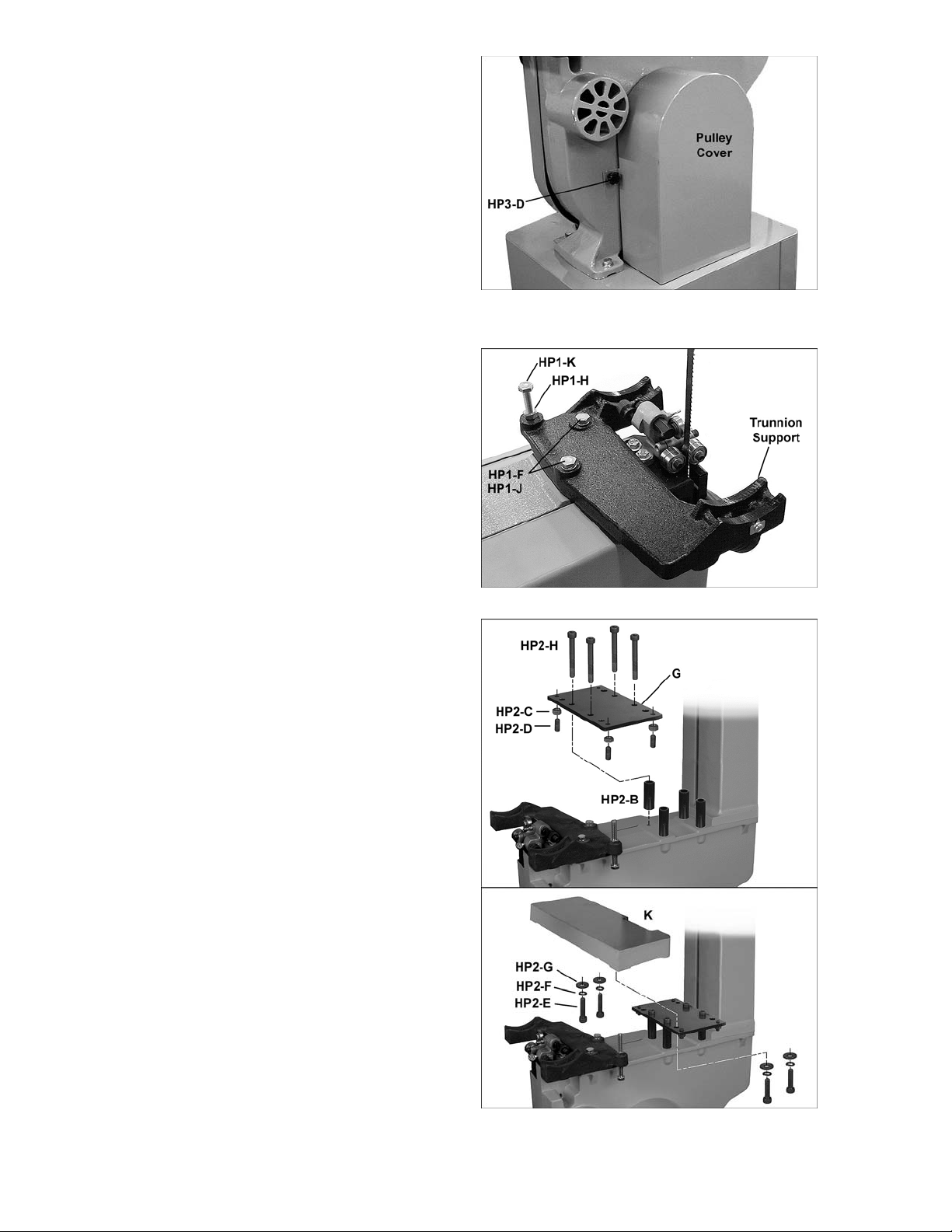
Installing Trunnion Support
Refer to Figure 21.
1. Use the two locating pins attached to the
saw body to help position the trunnion
support. Attach trunnion support to saw
body with two M8x30 hex cap sc rews (HP1-
J) and two M8 lock washers (HP1-F).
Tighten with a 1/ 2” wrench.
2. Thread M8 hex nut (HP1-H) onto t he M8x80
hex cap screw (HP1-K) and install into the
trunnion support as shown. Finger tighten
the hex nut; this will be f ully tightened l ater
for the 90° table stop sett ing.
Installing Extension Table
Refer to Figure 22.
1. Install a M8 hex nut (HP2-C) on each of the
four M8x20 set screws (HP2-D), then install
these set screws into t he four outer holes of
the level board (G), as shown.
2. Leave t he set screws fl ush with the top side
of the level board for now. These will be
adjusted later during leveling.
Figure 20
3. Place four spacers (HP2-B) over the holes
in the saw body, and pl ace the level board
on them, as shown. Ali gn t he four innerm ost
holes of the level board with the spacers,
and insert four M8x65 socket head cap
screws (HP2-H). Firmly tighten these screws
down into the base through the spacers,
using a 6mm hex wrench.
4. Position the extension table (K) over the
level board. Insert four M6x25 sock et head
cap screws (HP2-E) with four M6 lock
washers (HP2-F) and four M6 flat washers
(HP2-G) up through the rem aining holes of
the plate and into the underside of extension
table. Hand ti ghten only at this time.
Installing Main Table
Refer to Figure 23.
1. To m ount the main table, remove t able pin
by pulling it straight out, twisting it if needed.
Remove the table insert by pushing it up
from beneath t he table.
2. Rotate the tabl e so that the sa w bl ade will
slide through the slot in the table. Then
orient the t able so the screws will sli de into
the holes on the trunni on support, as shown
in Figure 23. Attach the two table locking
knobs (HP1-E) to t hese screws and ti ghten.
Figure 21
3. Re-install table pin and table insert.
Figure 22
14
Page 15
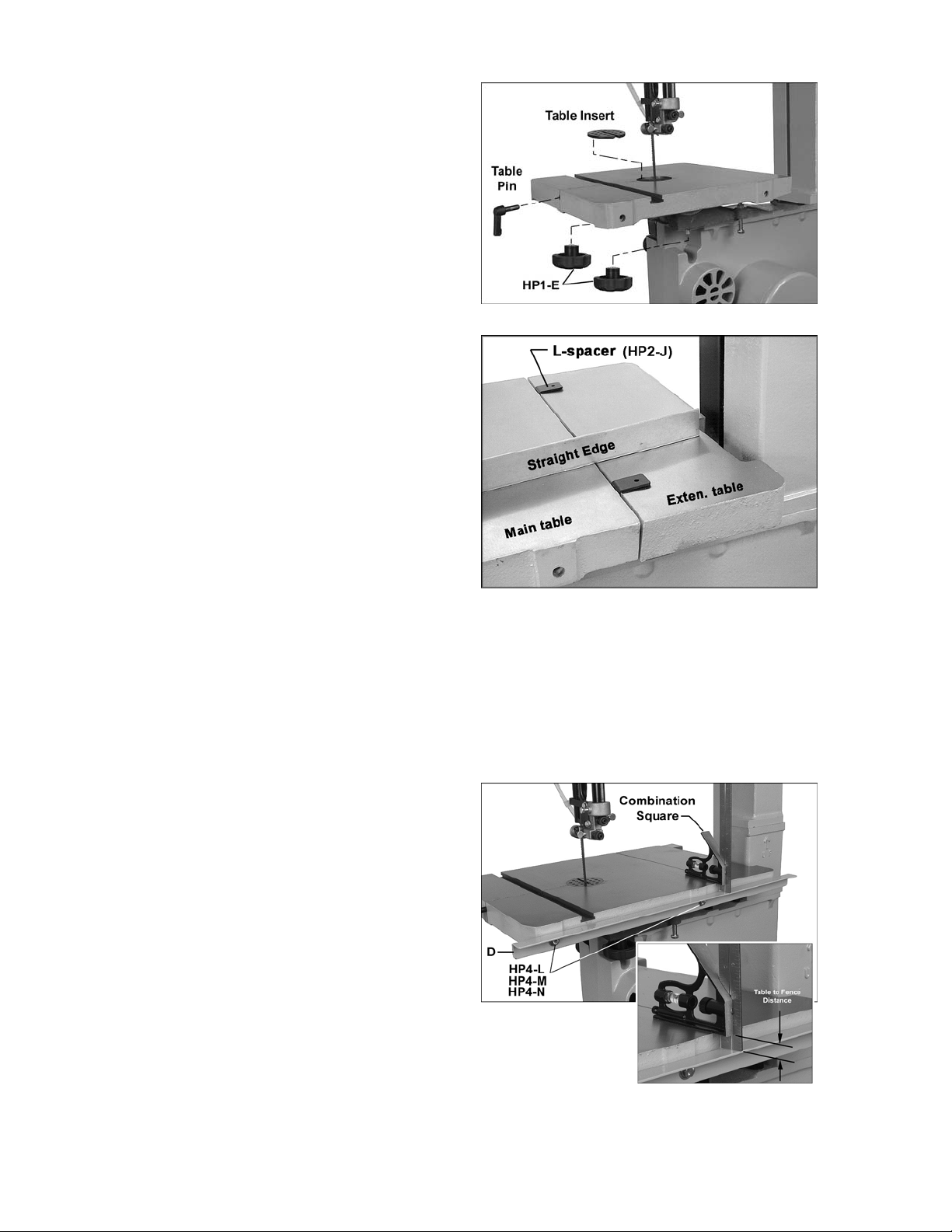
Leveling the Extension Table
NOTE: Before leveling the extension table, the
90-degree stop of the main table should be
verified. Read “Adjusting 90° Table Stop” on
page 20, then retur n to t his page.
Refer to Figures 22 and 24.
1. Position the main table at 90-degrees and
tighten the table locking knobs.
2. Place a straight edge (Figure 24) across
both tables, at several points along the
tables. If t he extensi on table is not l evel wit h
the main tabl e, use the level board beneath
to achieve this, as follows.
3. With the four M6x25 socket head cap
screws (HP2-E, Figure 22) still slightly
loose, loosen the hex nut s (HP 2-C) and t urn
any of the four set screws (HP2-D) with a
4mm hex wrench, t o raise or l ower that par t
of the extension table.
4. When the extension table is level with the
main tabl e, use a 1/2” wrench to tight en the
hex nuts (HP2-C) up against the level
board, to secure the setting of the set
screws.
Figure 23
5. Adj ust the gap between the extension t able
and the main tabl e. This gap can be easil y
set by using the pr ov ided L- spacers (HP2- J)
(Figure 24). Place the L-spacers between
the tables as shown, and nudge the
extension t able toward the m ain table as far
as it will go.
6. Snug the socket head cap screws (HP2-E)
with a 5mm hex wrench, a nd remov e the Lspacers.
7. Tilt the main t able to ensure that i t does not
rub against the edge of the extension table.
8. Securely tighten the four socket head cap
screws (HP2-E), making sure the extension
table doesn’t shif t during tightening.
Installing Rear Rail
Refer to Figure 25.
1. Disconnect machine from power source.
2. Install rear rail (D) to the main table using
two M6x20 hex cap screws (HP4-L), two
1/4" lock w ashers (HP4-M ) and two 1/4" flat
washers (HP4-N). Finger tighten only.
Figure 24
3. The rear r ail should lie parall el to the table
top. Place a combination square on the
main table at one end of the rear rail to get a
measurement showing tabl e-to- rail di stance,
as shown. Check t he other end of the fence;
the measurement shoul d be the same.
Figure 25
15
Page 16

4. Shift either end of the fence as needed to
gain identical distance from tabl e top.
5. Ti ghten both screws in the rear r ail using a
10mm wrench.
Installing Front Rail and Rip Fence
Refer to Figures 26 t hr ough 29.
1. Install front rail (E, Figure 26) to the main
table using two M6x20 hex cap screws
(HP4-L), two 1/4" lock washers ( HP 4- M ) and
two 1/4" flat washers (HP4-N). Finger
tighten only at t his tim e.
2. Install guide rail (B, Fi gure 27) to the slot s in
the front rail using three M6x20 hex cap
screws (HP4-L), three 1/4" lock washers
(HP4-M) and three 1/4" flat washers (HP4-
N). Tighten with a 10mm wrench.
3. Attach the fence (C, Fi gure 28) to the fence
body (P) with four 5/16”x3/4” hex cap
screws (HP4-H), four 5/16” lock washers
(HP4-J) and four 5/16” flat washers (HP4-K).
Tighten the screws with a 12mm wrench.
4. At the rear of the fence, thread a 1/4” hex
nut (HP4-D, Figure 29) onto the sliding pad
(HP4-G) and insert the sliding pad through
the fence and r ear hook (HP4-C). Secure in
place using a 1/4” flat washer (HP4- E), 1/4”
lock washer (HP4-F) and a 1/4” hex nut
(HP4-D). The rear hook should be adj usted
so that it overlaps the rear rail by
approxim ately 1/8".
Figure 26
Figure 27
5. Hook t he fence assembly over the rear rail,
and onto the guide rai l, as shown in Fi gure
28.
6. When t he fence assembl y is placed on the
table, the rear hook (HP4-C) should be
almost contac ting the undersi de of the rear
rail, as shown. The sliding pad will ride
along the top of the rear r ail.
Setting Fence-to-Table Gap
The gap between the bottom of the rip fence
and the table t op should be high enough that the
fence will not scrape along the table, yet low
enough that thi n workpieces won’t slip beneath
it. The gap should be equ al along the l ength of
the fence. Adjust as follows:
Refer to Figures 29 and 30.
1. Lock the f ence assembly t o the front rail by
pushing the fence handle down. The front
rail screws should still have “play” in them.
2. Lift up on bot h guide rail and fence toget her
until the f ence/table gap at the front edge of
the table is acceptable.
Figure 28
Figure 29
16
Page 17

3. Tighten bot h scr ews on the front rail (HP4-L,
Figure 26) with a 10mm wrench.
4. Adjust the height of the sliding pad at the
rear of the fence (Figure 29) if further
adjustment i s needed to even the gap along
the length of the fenc e.
Aligning Fence to Blade
Refer to Figure 31.
1. Place the table at 90-degrees. (Make sure
the 90° Tabl e Stop sett ing has been v erifi ed
– see page 20.)
2. Lock the fence to the guide rail with the
handle.
3. Place a square on t he table and agai nst the
fence, as shown in Figure 31.
4. If the fence is not square to the table,
slightly loosen the two screws in the front
rail (see Figure 26) and raise or lower one
end of the f ront rail assembly until f ence is
square to table.
5. Re-tighten screws. The fence face is now
square to the tabl e, and thus parallel to the
blade.
The fence must al so be set so that it aligns wit h
the blade front- to-back, as follows:
6. Move the fence so that it just contacts the
blade without bendi ng it, and lock t he fence
to the guide rail.
7. Check that the fence is aligned with the
blade; that is, it contacts front and back of
blade evenly. If the fence does not al ign with
the blade, loosen the four hex cap screws
(HP4-H).
8. Align t he fence wit h the blade, t hen tighten
the four hex cap screws.
Figure 30
Figure 31
Checking zero setting
Refer to Figure 31.
1. With the fence now aligned with the blade,
and still contacting the blade as shown in
Figure 31, check to see that the pointer is
aligned wit h zero on t he guide r ail scale.
2. If minor adjustment i s necessary, l oosen the
screw that holds the pointer in place, and
adjust the poi nter. Re-tighten the screw.
3. If major adjustment i s necessary, l oosen the
guide rail screws (HP4-L, Figure 27), and
slide the entire fence/ guide rail t ogether until
the fence just contac ts the bl ade. Re- ti ghten
guide rail screws, and make further minor
adjustment wit h the pointer.
17
Page 18

NOTE: The pointer’s zero position should be
tested later by cutting a straight piece of stock,
carefully measuring its width, and comparing it
to the scale reading.
Resaw Guide
Refer to Figure 32.
For resawing operati ons, att ach the r esaw guide
(HP4-A) to the fence using the knob (HP4-B)
through the slotted hole. Position the resaw
guide so that it is centered approximately with
the front edge of t he saw blade.
The resaw guide offers a taller, single-point
contact surface that allows pivoting of the
workpiece in order to keep the blade on the
cutting line.
Blower Nozzle
Refer to Figures 33 and 34.
1. The air hose, which is already connected to
the saw body, should be inserted through
the hole in the stand (visible in Figure 16)
and connected to the nozzle of the air
regulator on the motor (Figure 33). Use a
lighter or match to briefly heat the end of the
hose so that it will slip over the nozzle. A s it
cools, it will form a tight seal over the
nozzle.
Figure 32
Figure 33
2. Attach the plate (HP1-A) to the blade guide
assembly.
3. Connect the top end of the air hose to the
plate (HP1-A) with the M5x12 pan head
screw (HP1-D) through the cord clamp
(HP1-C). Heat the end of the hose with a
lighter or m atch, then push the wide end of
the nozzle (HP1-B) into the hose; the
tapered end points down toward the tabl e as
shown.
Work L amp
Refer to Figure 35.
The goose-neck l am p uses a m edium base l ight
bulb (not prov ided) which should be 60 watts or
less. The work lamp is operated independentl y
of the main saw switch.
IMPORTANT: If you are using 115 volt power
for the band saw, use a standard 110 v olt light
bulb. If you are using 230 volt power for the
band saw, discontinue use of the prov ided lamp,
and use an alternat e lamp with an independent
power cord.
Figure 34
Figure 35
18
Page 19

Installing Quick Tension Lever
Refer to Figure 36.
Install the quic k tension lever (M) onto the shaft
as shown, and tight en the two set screws using
a 3mm hex wrench. T he m ov ement of t he blade
tension lever is explained under “Installing
Blades”.
Stand Attachments
Refer to Figure 37.
1. Mount the two miter gauge hooks (HP3-B)
to the side of the stand with two M8x16
carriage bolts (HP 3-E) and two M8 flanged
hex nuts (HP3-F ). Position the hooks at an
angle, similar to that shown in Figure 38.
The miter gauge can be stored in these
hooks.
2. Mount the blade hook (HP3-C) with two
M4x10 pan head screw s (HP3- H) as shown.
The blade hook can store a roll ed-up spare
blade.
3. Mount the two fence hooks (HP3-A) to the
opposite side of the stand with two M8x16
carriage bolts (HP 3-E) and two M8 flanged
hex nuts (HP3-F). The rip fence can be
stored in these hooks when not i n use.
Dust Collection
Refer to Figure 38.
The use of a dust collection system (not
provided) is strongly advised when using the
band saw. It will hel p keep your shop clean, and
reduce the ri sk of heal th problems due to wood
dust inhalation. The dust collector should have
sufficient capacity for this size band saw
(minimum 350 cubi c feet per mi nute).
Figure 36
Figure 37
Connect a 4” diam eter dust coll ection hose (not
provided) to the port at the back of the band
saw, and secure tightly with a hose clamp, as
shown.
Note: Dryer vent hose is not suitable for dust
collection pur pose s.
Riser Block Accessory
A Riser Block kit (stock no. 1791217, not
provided) is available as an accessory. When
install ed, it increases resaw capacit y (workpiece
height capacity) to 12 inches. If you have
purchased the Riser Block, consult the
instruction sheet that accompanies it.
Figure 38
19
Page 20

Adjustments
Tilting the Table
Unplug the machine from the
power source before making any repair or
adjustment.
Refer to Figure 39.
1. Loosen the table l oc ki ng k nobs.
2. Til t table up to 45 degrees to the right. T he
angle is indic ated on the trunnion scale.
3. Tighten the table locking knobs.
4. You can place a measuring device on the
table and against the blade t o verif y the 45°
setting.
Adjusting 90° Table Stop
Refer to Figures 39 and 40.
1. Disconnect machine from power source.
2. Loosen tabl e locking knobs and tilt table t o
the left until it rests against the table stop
screw.
Figure 39
3. Use a square placed on the table and
against the bl ade, as shown in Figure 40, to
verify that the table is 90 degrees to the
blade. Make sure the table insert is level
with the table surface, to ensure an acc ur ate
reading.
4. If an adjustm ent is necessary, tilt the table
out of the way and tight en the table locking
knobs.
5. Loosen jam nut (Figure 39) and turn table
stop screw left or right to raise or lower the
stop. Tighten jam nut down against the
trunnion support t o hold table stop screw in
place.
6. Unlock the table and tilt it back on to the
table stop screw to confirm table is 90
degrees to the blade. Repeat this process
as necessary unti l tabl e is 90 degrees to the
blade.
7. Make sure pointer (Figure 39) indicates
zero. If it does not, l oosen screw and mov e
pointer to align wi th zero. Re-tighten screw.
NOTE: After adjusting the 90-degree stop, it
may be necessary t o re-set the ext ension table
so it is level with the main tabl e. See “Leveling
the Extension Table. ”
Figure 40
20
Page 21

Table Aligned with Blade
For accurate crosscuts using the miter gauge,
the table (i.e. miter slot) must be aligned with the
blade. This alignment has been set by the
manufacturer, but the operator may wish to
verify it, as follows. NOTE: This procedure
works best with a wide bl ade.
Refer to Figure 41.
1. Place a straightedge along the side of the
blade, with very light pressure (do not
deflect the blade). The straightedge should
contact bot h front and back of blade.
2. Measure carefully with a fine rule from the
straightedge to the edge of the miter slot.
Do this at front and back of the table; the
distance should be the same.
3. If the mit er slot is not aligned wit h t he blade,
slightly loosen the six screws holding the
trunnions to t he table.
4. Nudge the table as needed, until the miter
slot is aligned wit h blade (distances are the
same front to back ).
5. Tighten trunnion screws. (NOTE: After this
adjustment, the alignment of fence to blade
may need to be re-checked. See “Aligning
Fence to Blade” on page 17.)
Figure 41
Installing Blades
Unplug the machine from the
power source before removing or installing
blades.
The PWBS-14CS Band S aw is provi ded with a
3/8” wide x 0.020 thi c k x 93.5” long, 6TPI blade.
Refer to Figure 42.
The blade tension lever is a patented Carter®
Quick-Rel ease™ lever, and has three positions:
high (tension) , mi ddle (partial tension), and low
(blade rel ease). Push the lever up slightly, then
out, and mov e it into positi on, allowing it to rest
on the appropriate ledge of the block.
1. Disconnect machine from power source.
2. Move tension lever to blade release
position, as shown in Fi gur e 42.
(Note: When using t he larger width blades,
it may also becom e neces sary to l oosen t he
tension knob to release al l tension.)
3. Remove the table insert and the table pin.
4. Open both wheel guards.
5. Back off t he upper and lower guide beari ngs
so that nothing conflicts with the blade.
Figure 42
21
Page 22

6. Remove the current blade from the upper
wheel, then t he lower wheel. Turn blade to
direct it through t he sl ot in the table.
New blades are usually
packaged in co iled position. Use gloves and
grasp the coil with one hand while slowly
uncoiling the blade with the other hand.
7. Guide new blade through table slot. Place
blade in upper and l ower blade guide s, and
around upper and lower wheels.
Note: Make sure blade teeth point forward
and down toward t he table. If the teeth won’t
point downward no matter how you orient
the blade, then the blade is twisted insideout. Remove blade and, usi ng gloves, twist
it into correct ori entation, then re-install.
8. Position blade so it lies on t he c enter of bot h
upper and lower wheels.
9. Raise tension lever to partial tension
position.
10. Re-install table insert and table pin.
11. Tension and track the blade before
operating saw. Proceed to "Blade Tension"
and “Blade Trac k ing" .
Blade Tension
Refer to Figure 43.
1. Disconnect machine from power source.
2. Place tension lever in full tension position
(see Figure 42).
3. Turn blade tension knob (Figure 43)
clockwise to t ension blade. A gauge on the
upper wheel slide bracket indicates the
approximate tension according to the width
of the blade. Initially, set the blade tension
to correspond to bl ade width.
The ten sion lever must b e in
highest (tension) position when setting blade
tension. Failure to comply may cause
damage to locating block at base of lever.
As you become fami liar with the saw, you may
find it necessary to change the blade tension
from the initial setting. Changes in blade width
and the type of material being cut will have an
effect on blade tension. Keep in mind that too
little or too much blade tension can cause bl ade
breakage.
Figure 43
TIP: If the band saw is to sit idle for a period of
time while the blade is installed, place tension
lever in partial tension position; this will help
prevent blade f atigue and tire deform ation, and
save wear on bearings and band wheel s.
22
Page 23

Blade Tracking
Disconnect machine from
power source. Do not adjust blade tracking
with the machine running.
“Tracking” r efers to how the blade is posit ioned
on the wheels whil e in moti on. The bl ade should
track approximately in t he c enter of both wheels,
as shown in Fi gure 44. Track ing on the PW BS14CS Band Saw has been factory-adjusted;
however, it should be checked periodically,
including aft er ev er y bl ade c hange.
Refer to Figure 45.
1. The blade must be properly tensioned
before adjusting blade tracking. Make sure
blade guides and blade bearings do not
interfere with the blade.
2. Place the tension lever at full tension
position.
3. Open the upper door and rotate the upper
wheel forward by hand. Observe the
position of the blade on t he wheel - it should
be in the center.
Figure 44
4. If the bl ade tends to shift t o one side or the
other of the wheel, loosen wing nut (Figure
45).
5. If the blade i s tr acki ng toward the f ront edge
of the wheel, rotate the tracking knob
clockwise – the upper wheel will tilt toward
the back and the blade will move to the
center of the wheel.
If the bl ade is tracking toward the back edge
of the wheel, rotate the tracking knob
counterclockwise: the upper wheel will tilt
toward the f ront and the blade will move t o
the center of the wheel.
IMPORTANT: This adjustment is sensitive;
perform it in small increment s and give the
blade time to react to the changes, as you
continue to rot ate the wheel.
6. When blade is tracking properly at the
center of the wheel, r e- tighten the wing nut.
7. Turn on saw and verify proper tracking while
the machine is running.
8. If further tracking adjustments are needed,
disconnect from power, and repeat
instructions above.
Figure 45
Guide Post and Upper Blade Guard
Refer to Figure 46.
1. Disconnect machine from power source.
Figure 46
23
Page 24

2. Loosen lock knob and raise or lo
w
blade guide assembly to approximately
3/16” above the material being cut.
3. Tighten lock knob.
4. The guide post (Fi gure 46) is spring l oaded.
To adjust the tension on the spring, unscre w
and completely remove knob, then tighten
or loosen set screw, until desired tension is
reached. Re-i nstall knob.
er upper
Upper Bearing Guides
Refer to Figures 47, 48, 49.
1. Disconnect machine from power source.
2. Blade must already be tensioned and
tracki ng properly.
3. Loosen thumb screw (A, Figure 47) and
move guide block by turning knob (B) so
that the front of the guide wheels (C) are
just behind the gullet (curved area at base
of tooth) of the blade, as shown in Figure
48. This di stance is usually about 0.016” ( or
1/64”).
4. Tighten thumb screw (A, Figure 47).
5. Loosen the socket screw (D) and turn the
screw (E) on each guide wheel to m ov e the
guide wheels about 0.004” from the blade.
(A quick way to set t his distance is t o place
a crisp dollar bill, which is approximately
.004” thic k, between guide wheel and bl ade,
and move t he guide until it just contact s the
bill.)
6. Tighten socket screw (D) when adjustment
is satisfactory.
Figure 47
Figure 48
Thrust Bearing
The thrust bearing (F, Figure 49) supports the
back edge of t he blade during operat ion, and is
set so that the blade will c ontact it only when the
blade is under pressure during a c ut.
7. Loosen thumb screw (G, Figure 49) and tur n
knob (H) to move the thrust beari ng (F) in or
out until t he bearing is approxim ately 0. 016”
(or 1/64”) behi nd the blade. You can use a
feeler gauge to set this distance, or simply
place a crisp dollar bill folded twice (four
thicknesses) between the thrust bearing and
the blade. (A dollar bill is approximately
0.004” thick, so four thicknesses provides
the necessary distanc e.)
8. Tighten thumb screw (G, Figure 50).
Lower Bearing Guides
Refer to Figure 50.
1. Disconnect machine from power source.
Figure 49
Figure 50
24
Page 25

2. Blade must already be tensioned and
tracki ng properly.
3. Loosen thumb screw (J) and move guide
block by t urni ng knob (K) so that t he front of
the guide wheels (L) are just behind the
gullet (curved area at base of tooth) of the
blade.
4. Tighten thumb screw (J).
Thrust Bearing
5. Loosen thum b screw (M) and turn knob (N)
to move the support bearing (O) in or out
until the beari ng is approxim ately 0.016” (or
1/64") behind the blade. You can use a
feeler gauge to set this distance, or simply
place a dollar bill folded twice (four
thicknesses) between the support bearing
and the blade. (A dol lar bill i s .004” t hic k, so
four thicknesses provides the necessary
distance.)
6. Tighten thumb screw (M).
7. Loosen the socket screw (P) and turn the
screw (R) on each gui de wheel to mov e the
guide wheels about .004” from the blade.
Tighten socket screw (P) when finished.
Miter Gauge
Refer to Figures 51, 52.
Figure 51
Figure 52
A miter gauge is provi ded for crosscutti ng. Slide
the miter gauge i nto the T-slot from the edge of
the table.
To use the mit er gauge, loosen the handle and
rotate the gauge body u nt il t he desired angl e on
the scale lines up with the pointer. Tighten
handle.
For preci se crosscuts, t he 90° angl e of t he mit er
gauge to the blade can be verified as follows
(Refer to Figure 52). A wide blade works best for
this procedure.
1. Set the miter gauge at 90°.
2. Place a square agai nst the mi ter gauge and
against the bl ade, as shown.
3. Adjust t he miter gauge until t he square lies
flush against bot h it and the blade.
4. Loosen the screw and shift the pointer as
needed. Retight en scr ew.
The miter gauge, when not in use, can be
placed int o the hooks on the stand. See Figur e
53. Loosen the miter gauge handle, and slide
the miter gauge into the top hook. Pivot the
miter gauge bar into the lower hook, then tight en
the miter gauge handle to secure the miter
gauge to the stand.
Figure 53
25
Page 26

On/Off Switch
The band saw is equipped with a push-button
switch that will accept a safety padlock (not
included). To safeguard your machine from
unauthorized operation and accidental starting
by young chil dren, the use of a padl ock is hi ghly
recommended – see Figur e 54.
Maintenance
Before doing maintenance,
disconnect machine from electrical supply
by pulling out the plug or switching off the
main switch! Failure to comply may cause
serious injury.
Clean the band saw regularly to remove any
resinous deposits and sawdust. Use a brush,
vacuum or compressed air to blow out excess
dust. (Wear safet y goggles while doing this.)
Keep the mit er slot in the table free of dust and
debris. Keep the gui de bearings clean and free
of resin. Use a commercially avail able gum and
pitch remover if needed.
Keep the guide po st clean; occasionall y apply a
light coat of oil.
Oil any pi ns, shaf ts, and j oi nts. Do not get oi l on
pulleys or belt s.
Bearings on the band sa w are sealed for life and
do not require att ention.
Check that the cleaning brush over the lower
wheel is working proper ly; adjust if necessary.
Remove any deposits from the band wheels and
tires to avoid vibration and blade breakage.
NOTE: Do not use s olv ents around tires. If signs
of wear or deform ation occ ur , replace the tires.
Figure 54
The table surf ac e m ust be k ept clean and fr ee of
rust for best results. If rust appears, use a
mixture of household ammonia, a good
commercial detergent and #000 steel wool.
Alternatively, commercial rust removers can be
found at many hardware stores.
Apply a light, protective coating over the table,
such as paste wax. Product s in aerosol f orm are
also available in hardware stores and supply
catalogs. Whatever method is chosen, the
coating should protect the metal and provide a
smooth surf ac e, wit hout staining the wood.
26
Page 27

Blade Selection
Using the proper bl ade for the job will incr ease
the operating ef ficiency of your band saw, help
reduce necessary saw maintenance, and
improve your pr oduc tivity. Thus, it is import ant to
follow certain guidelines when selecting a saw
blade.
Here are factors to consider when selecting a
blade:
• The type of materi al y ou will be c utti ng.
• The thickness of the workpi ec e.
• The features of the workpiece, such as
bends or curves wit h small radii.
These factors are important because they
involve basic concepts of saw blade design.
There are five (5) blade features that are
normally changed to meet certain kinds of
sawing requirements. They are:
1. width
2. pitch (number of teeth per inch)
3. tooth form (or shape)
4. the “set” of the teeth
5. the blade material itself
A fine pi tch (more teet h per inch) will cut slowly
but more sm oothly. A coar se pitch (f ewer teeth
per inch) will cut f aster but more roughly.
As a rule of thumb, the thicker the workpiece,
the coarser will be the bl ade pitch. If you have to
cut a hard or very brittle material, you will
probably want to use a blade wit h a finer pitch i n
order to get clean c uts.
Using a blade with too few teeth may cause
vibration and a r ough cut, while too m any teeth
may cause the gullets to fill with sawdust and
overheat the blade.
As a general rule, try to use a blade that will
have from 6 to 12 teeth in the workpiece at any
given time.
Shape
Figure 56 shows comm on types of t ooth shape,
or form. Tooth shape has an effect on cutting
rate.
Width
Band saw blades come in different standard
widths, measured from the back edge of the
blade to the tip of the tooth. Generally, wider
blades are used for ripping or making straight
cuts, such as resawing. Narrower blades are
often used when the part being cut has curves
with small r adii. When cut ting straight lines with
a narrow blade, t he blade may hav e a tendency
to drift (see “Bl ade Lead” ) .
Pitch
Pitch is m easured in “ teet h per i nch” ( T. P.I.) and
can be constant or variable. Figure 55 shows
blades with different pitches.
Figure 56 – Blade Toot h Shape
The Regular, or standard blade, has evenly
spaced teeth that are the same size as the
gullets, and a zero-degree rake (i.e. cutting
angle). T hese offer precise, cl ean cuts at slower
rates. It is usually a good choice for cutting
curves and making cr osscuts.
The Skip type has fewer teeth and l arger gullet s
with a zero rake. It allows faster cutting rates
than the Regular type, with a slightly coarser
finish. It i s useful for re-sawing and rippi ng thick
stock, as well as cutti ng softwoods.
The Hook ty pe blade has l ar ger teeth and gullet s
and a positive rake angle for more aggressive,
faster cutting when re-sawing or ripping thick
stock, especially hardwoods.
Figure 55
Variable-tooth blades combine features of the
other shapes, with tooth style and spacing
varying on the same blade. This produces
smooth cuts whil e dam pening v ibration.
27
Page 28

Set
The term “set” ref er s to the way in which the saw
teeth are bent or positioned. Bending the teeth
creates a kerf that is wider than t he back of t he
blade. This hel ps the operator m ore easily pivot
a workpiece through cur ve cuts, and decrease s
friction bet ween blade and workpi ece on strai ght
cuts.
Set patterns are usually selected depending
upon the type of material that needs to be cut .
Three comm on set patt erns ar e sho wn in F i gure
57.
Blade Breakage
Band saw blades are subject to high stresses
and breakage may sometimes be unavoidable.
However, many f actor s can be controlled t o hel p
prevent most blade breakage. Here are some
common causes for break age:
1. Misalignment of the blade guides.
2. Feeding workpiec e too quickly.
3. Using a wide blade to cut a tight radius
curve.
4. Excessive tension.
5. Teeth are dull or impr oper ly set.
6. Upper guides are set too high off the
workpiece.
7. Faulty weld on bl ade.
Although not essential, some users round or
“stone” the back edge of their blade. This is
done by placing a s harpeni ng stone on the tabl e
and in li ght contact with t he back corners of t he
blade as the blade is running. Rounding can
help the back blade edge m ove more smoothly
through the kerf, smooths the weld, and helps
prevent crack s fr om start ing at the back corners.
Figure 57
Generally, the Raker set is used for cutting
metal workpieces; the Wavy set, when the
thickness of the workpiece changes, such as
cutting hol low tubi ng or struc tural s. The Straight,
or Alternate, set is the one most used for
woodworking blades, and is also used to cut
plastics.
Material
Band saw blades can be made from different
types of metals. The most common include
spring steel, carbon steel, bimetal (alloy steel
equipped with a high speed cobalt steel edge
welded to it), or carbide tips.
Because of the im portance of blade sel ection, it
is recommended that you use the blade
selection guide on page 35. Also, listening to
experienced band saw users will provide
valuable information as to the types of blades
currentl y on the market along wit h their pros and
cons.
28
Page 29

Operation
The following sect ion c ontains basic i nf ormati on,
and is not intended to cover all possible
applicati ons or techniques using the Band Saw.
Consult published sources of information,
acquire formal training, and/or talk to
experienced Band S aw us ers t o gain pr of i ciency
and knowledge of band saw operations. (The
Figures used may or may not show your
particular saw model, but the procedures are
identical.)
General Procedure
1. Make sure t he bl ade is adj usted correc tly for
tension and tracking, and that upper and
lower guide beari ngs and thr ust bear ings are
set in proper relati on to the blade.
Ripping
Ripping is cutting lengthwise down the
workpiece, and with the grain (of wood stock).
See Figure 58. Always use a push stick or
similar safety device when ripping narrow
pieces.
2. Adjust gui de post so that the guide bear ings
are just above the workpiece (about 3/16”)
allowing minim um ex posure t o the blade.
3. If using the f ence, move i t into position and
lock it t o the guide rail. If you are usi ng the
miter gauge for a crosscut, t he fence should
be moved safely out of the way.
4. Turn on the band saw and allow a few
seconds for t he machine to reach full speed.
Whenever possible, use a
push stick, hold-down, power feeder, jig, or
similar device while feeding stock, to prevent
your hands getting too close to the blade.
5. Pl ace the straightest edge of the workpiece
against the f ence f or a rip c ut; or against t he
miter gauge for a crosscut. Push the
workpiece slowly into the blade, while also
keeping it pressed again st the f ence or held
against the miter gauge. Do not force the
workpiece int o the blade.
Some further operat ing tips:
Make relief cuts whenever possibl e. A relief cut
is an extr a cut made through t he waste porti on
of a workpiece up to the layout line. When that
intersection is reached by the blade while
following the layout line, the waste portion
comes free. This helps prev ent pinching of the
back edge of the blade in t he cut.
Figure 58
Crosscutting
Crosscutting is cutting across the grain of the
workpiece, while using the miter gauge to feed
the workpiece i nto the blade.
The right hand shoul d hold the workpiece steady
against the miter gauge, while the left hand
pushes the miter gauge past the blade, as
shown in Figure 59.
Figure 59
Do not use the fence in conjunction with the
miter gauge. The offcut of the workpiece must
not be constrained during or after the cutting
process.
When cutting, do not
overfeed the blade; overfeeding will reduce
blade life, and may cause the bl ade to break.
When cutting long stock, the operator should
use roller stands, suppor t tabl es, or an assistant
to help stabilize the workpiece.
Using the fence in
conjunction with the miter gauge can cause
binding and possible damage to the blade.
29
Page 30

Resawing
Resawing is the process of slicing stock to
reduce its thickness, or to produce boards that
are thinner t han the origi nal workpiece, such as
veneers.
The ideal bl ade for resawing is the widest one
the machine c an handle, as the wider the bl ade
the better it can hold a str aight line.
Resawing can be per formed using t he rip f ence
or the resaw guide. When using the rip fence,
use a push block, push stic k, or simil ar device to
keep your hands away from the blade. The
resaw guide offers a pivot point by which you
can carefully follow your layout line; it is
especially useful for sawing curves, when the
fence can’t be used and it’s difficult to c ontrol the
cut freehand.
Figure 60 demonstrates resawing with the rip
fence; Figur e 61, wit h the resaw guide.
It is more common with small, narrow blades,
and is almost always attributable to poor blade
quality, or lack of proper adjustments. Inspect
the band saw for the following:
• Fence is not parallel to miter slot and blade.
• Blade is not tensioned c or r ec tly.
• Blade is dull.
• Teeth have too much “set” on one side of
the blade.
• Workpiec e is bei ng fed t oo quic kl y.
Figure 62
Figure 60
Figure 61
Blade Lead
Blade lead, or drift, is when the blade begins to
wander off t he cutting li ne even when the band
saw rip fence i s being used. Figur e 62 shows an
example of blade lead.
If the blade is suspect, but replacing it is not
currently an option, the blade lead can be
temporarily compensated for by skewing the
fence:
1. Cut a scrap pi ece of wood about the same
length as the band saw tabl e, and joint one
edge along its lengt h, or rip it on a table saw
to give it a straight edge.
2. Draw a line on the board parallel with the
jointed, or str aight edge of the board.
3. Move the band saw fence out of the way,
and carefully make a freehand cut along
your drawn line on the board. Stop about
midway on the board, and shut off the band
saw (allow the blade t o come to a complete
stop) but do not all ow the board to move.
4. Clamp the board to the table.
5. Loosen the four hex cap screws on the
fence and slide the fence over, lining it up
against the board. Loc k the f enc e down.
6. Re-tighten the four hex cap screws.
NOTE: Skewing the f ence to correct blade lead
is effectiv e for that particular blade; when a new
blade is installed, the fence will need readjustment and re-squaring to miter slot. See
appropriate sect ions in this manual.
30
Page 31

Troubleshooting – Mechanical and Electrical Problems
Trouble Probable Cause Remedy
Machine will not
start/restart or
repeatedly trips
circuit breaker or
blo ws f u ses.
No incoming power.
Electri c al cord damaged. Replace cord.
Building circuit breaker trips or f use
blows.
Switch or motor f ailur e ( how to
distinguish).
Motor overheat ed.
Motor failure.
Verify machine is connected to power
source.
Verify that band saw is on a circ uit of
correct size. If circuit size is correct,
there is probabl y a loose el ectr ic al
lead.
If you have access to a voltmeter, you
can separate a switch f ailure from a
motor fai lu re by fi r st, verifyin g
incoming volt age at 110 +/-10% [or
220 +/-10%] and second, check ing
the voltage between switc h and
motor. If inc omi ng v oltage is incorrect,
you have a power supply problem. If
voltage between start er and m otor is
incorrect, y ou hav e a starter pr oblem.
If voltage between starter and motor
is correct, you hav e a motor pr oblem.
Clean motor of dust or debri s to allow
proper air circulation. Allow motor to
cool down before r estar ting.
If electri c mot or i s suspect, y ou have
two options: Have a qualified
electrician test the motor for function
or remove the motor and take it t o a
qualified elec tric motor repair shop
and have it tested.
Band Saw does not
come up to speed.
Miswiring of the unit.
Swit c h failure.
Extension cord too light or too long.
Low current. Contact a qualified electrician.
Confirm that all elec trical connections
are correct.
If the start/ stop switc h is suspect, you
have two options: Have a qualified
electrician test the switch for function,
or purchase a new start/stop switch
and establish if t hat was the problem
on change-out.
Replace with adequat e si z e and
length cord.
31
Page 32

Troubleshooting – Operating Problems
Trouble Probable Cause Remedy
Table tilt does not
hold position under
load.
Table will not tilt . Trunnion is not lubricated. Grease the trunnion.
Table locking k nobs are not tight. Tighten locking knobs .
Saw vibrates
excessively.
Surface finish on
workpiece is rough.
Saw blade cutting
inaccuratel y . Cut s are
not straight .
Trunnion is jammed.
Stand is on uneven floor . Re-position on flat, level surfac e.
Drive belt is too sl ac k, or worn.
Motor plate screws or other har dware
on saw is loose.
Incorrect choi c e of saw blade pitch.
Saw dust or debris on band wheel. O r
tire is worn/dam aged.
Low shop voltage. Contact a qualified electrician.
Saw blade speed is too l ow. Increase speed.
Saw blade pitch is too c oar se. Change to finer pitch blade.
Blade mounted inc or r ec tly. Teeth should poi nt downward.
Angle pointer not set correctly.
Table stop not adjusted c or r ec tly.
Gum or pitch on blade. Clean blade.
Worn blade teeth or damaged blade. Replace blade.
Disassemble and r eplace jammed
parts.
Increase tension on drive belt.
Replace belt if worn.
Tighten all har dware.
Check blade selection chart and use
correct blade.
Keep band wheels clean. Replace
ti res if nec essary .
Check blade with square and adjust
pointer.
Check blade with square and adjust
stop.
Fence not parallel to blade. Align fence pr operl y ( see page 17).
Miter gauge adjusted improperly. Adjust miter gauge (see page 25)
Incorrect adjustment of blade guides.
Workpiec e being fed too strongly. Reduce feed force.
Upper blade guides not located close
enough to workpiece.
Incorrect choi c e of saw blade for that
particular c utti ng oper ation.
Blade tension too light. Increase tension (see page 22).
Adjust blade guides properly (see
pages 24-25).
Guides should be about 3/ 16” above
workpiece.
Change to correct blade.
32
Page 33

Trouble Probable Cause Remedy
Fence not ali gned with blade. Check and adjust fenc e ( see page 17)
Wood is warped. Select diff er ent wood.
“Blade lead” occurs
(blade wanders
during cut)
Blade cannot be
tensioned properl y .
Blade binds in the
workpiece.
Blade form s cracks at
base of teeth.
Excessive f eed r ate Reduce feed rate.
Incorrect blade being used for the
Change blade to corr ec t t y pe.
particular c ut being made.
Blade tension im pr oper ly set. Set blade tension acc or ding to blade
size.
Bearing guides not set pr oper ly. Adjust guides (see pages 24-25).
Tension spring i s fatigued. Replace tension spring (contact
service representative).
Incorrect blade tension or damaged
blade.
Blade too wide f or desired r adius.
Teeth not suitable for particular job, or
are incorrectly set.
Blade thick ness not suit able for band
whe el diameter.
Blade sharpened incor r ec tly,
becomes over heated.
Correct accordingly.
Select narrower blade. See chart on
page 35.
Replace with proper blade for job.
Replace with proper thickness blade.
Sharpen blade properly or replace.
Cracks on back edge
of blade.
Blade breaks
prematurely.
Band wheels have becom e
misaligned.
Workpiec e being fed too quickly.
Welding on blade not perfectly
aligned.
Thrust bearing is worn; caused by
constant contact with back of blade.
Contact servi c e r epr esentative.
Reduce feed speed to lessen strain
on the blade.
Eliminate the welded part, and re-
weld properly; or ac quir e a new blade.
Round the back edge of a new blade.
Replace thrust bear ing. Adjust new
bearing according to instructions.
Feeding workpiec e too quickly. Reduce feed force.
Blade guides misaligned.
Blade pitch too coar se, or wrong size
blade for particular cut (e.g., wide
blade to cut a tight radius).
Set bearing guides appropriate
distance from blade.
Refer to blade selection chart; use
appropriate blade for the operation.
Replace blade, or have blade
Blade overheat ed dur ing welding.
annealed, or eliminate brittle part and
weld correctly.
33
Page 34

Trouble Probable Cause Remedy
Replace blade, or have blade
Blade cooled too r apidly after welding.
annealed, or eliminate brittle part and
weld correctly.
Blade breaks cl ose to
weld.
Premature dulling of
saw teeth.
Thrust bearing not properly
supporting blade, or guide post/side
bearings set too high allowing flex.
Blade tensioned too tightly. Reduce tension (see page 22).
Blade overheat ed dur ing welding.
Blade cooled too r apidly after welding.
Blade “pitc h” too fine.
Feed pressure too li ght. Increase feed pr essure.
Cutting rate too low.
Incorrect choi c e of blade.
Chipped tooth or for eign object
lodged in cut.
Check all guide bearings for correct
position and signs of wear. A djust or
replace as needed.
Have blade annealed, or eliminate
brittl e part and weld c or r ectly.
Have blade annealed, or eliminate
brittl e part and weld c or r ectly.
Refer to blade selection chart. Use
blade with coarser pitch.
Increase feed pr essure and cutting
rate.
Re-examine material. Select proper
blade from the char t.
Stop the saw and remove lodged
particle. Replace blade if damaged.
Optional Accessories
1791217 ...... 6” Riser Block Kit
2042377 ...... Mobile Base for PWBS14-CS Band Saw
34
Page 35

Blade Selection Guide
Identify the material and thickness of your workpiece. The chart will show the recommended PITCH,
blade TYPE, and FEE D RATE.
Key: H – Hook L – Low
S – Skip M – Medium
R – Regul ar H – High
Example: 10/H/M means 10 teeth per inch / Hook Type Blade / Medium Feed
For Radius Cutting
Study the part drawing or prototype, or actually
measure the small est cutting radius required, and
locate this radius (in inches) on the chart at the
right. Follow the curve to where the approxim ate
blade width is specified. If a radius falls between
two of the curves, selec t the widest blade that will
saw this radius.
This procedure should be used for making initial
blade selecti ons. These recommendations can, of
course, be adjusted to m eet specific requir ements
of a cutting job. Compromises may be nec essary if
you cannot find all needed specifications in a
single blade.
35
Page 36

Replacement Parts
To order parts or reac h our service departm ent, call 1-800-274-6848, Monday throug h Friday (see our
website for business hours, www.powermati c.com). Having t he M odel Number and Serial Number of your
machine available when you call will allow us to serve you quickly and accurately.
Parts List: Body Assembly
Index No. P art No. Description Size Qty
1 ................ PWBS14-101 ............ Base......................................................................... ...................................... 1
2 ................ PWBS14-102 ............ Pin............................................................................ ...................................... 4
3 ................ BB-6204VV ............... Ball Bearing ............................................................. 6204VV ......................... 2
4 ................ PWBS14-104 ............ Lower Wheel Shaft .................................................. ...................................... 1
5 ................ 6291489 .................... Key........................................................................... 5 x 5 x 20 mm ............... 2
6 ................ PWBS14-106 ............ Retaining Ring ......................................................... S20........ ........................ 1
7 ................ PWBS14-107 ............ Pulley ....................................................................... ...................................... 1
8 ................ TS-1523031 .............. Socket Set Screw .................................................... M6 x 10 ......................... 2
9 ................ PWBS14-109 ............ Hex Head Bolt.......................................................... M16 x 55 ....................... 1
10 .............. TS-155010 ................ Flat Washer ............................................................. M16 ............................... 2
11 .............. TS-154010 ................ Hex Nut .................................................................... M16 ............................... 1
12 .............. PWBS14-112 ............ Hex Stud .................................................................. ...................................... 2
13 .............. PWBS14-113 ............ Lower Hinge............................................................. ...................................... 1
14 .............. TS-1534041 .............. Phillips Flat Head Machine Screw ........................... M5 x 10 ......................... 4
15 .............. PWBS14-115 ............ Hex Head Bolt.......................................................... ...................................... 2
16 .............. PWBS14-116 ............ Catch ....................................................................... ...................................... 2
17 .............. TS-1533042 .............. Phillips Pan Head Machine Screw ........................... M5 x 12 ......................... 3
18 .............. PWBS14-118 ............ Lower Wheel ............................................................ ........... ........................... 1
19 .............. PWBS14-119 ............ Wheel Tire ............................................................... ...................................... 2
20 .............. TS-1550061 .............. Flat Washer ............................................................. M8 ................................. 2
21 .............. PWBS14-121 ............ Hex Cap Screw ........................................................ M8 x 25(LH) .................. 1
22 .............. PWBS14-122 ............ Upper Wheel ............................................................ ...................................... 1
23 .............. PWBS14-123 ............ Retaining Ring ......................................................... R35 ............................... 2
24 .............. BB-6202ZZ ................ Ball Bearing ............................................................. 6202ZZ.......................... 2
25 .............. PWBS14-125 ............ Lower Wheel Guard ................................................. ...................................... 1
26 .............. TS-1540083 .............. Hex Nut .................................................................... M12 x 1.25 .................... 1
27 .............. .................................. Blade (local purchase) ............................................. ...................................... 1
28 .............. PWBS14-128 ............ Upper Back Cover ................................................... ...................................... 1
29 .............. PWBS14-129 ............ Pan Head Flanged Screw ........................................ M5 x 8 ........................... 2
30 .............. PWBS14-130 ............ Tapping Screw ......................................................... M4 x 8 ......................... 12
31 .............. PWBS14-131 ............ Rear Guard Blade .................................................... ...................................... 1
32 .............. PWBS14-132 ............ Upper Hinge............................................................. ...................................... 1
33 .............. PWBS14-133 ............ Oblong Metal Washer .............................................. ...................................... 2
34 .............. PWBS14-134 ............ Tapping Screw ......................................................... M3.5 x 16(AB) ............... 2
35 .............. PWBS14-135 ............ Upper Wheel Guard ................................................. ...................................... 1
36 .............. PWBS14-136 ............ Stud Latch................................................................ ...................................... 2
37 .............. PWBS14-137 ............ Star Washer (Internal) ............................................. M8 ................................. 2
38 .............. PWBS14-138 ............ Knob ........................................................................ M8 ................................. 2
39 .............. PWBS14-139 ............ Wheel Brush ............................................................ ...................................... 1
40 .............. TS-1540061 .............. Hex Nut .................................................................... M8 ................................. 1
57 .............. TS-1490071 .............. Hex Cap Screw ........................................................ M8 x 40 ......................... 4
58 .............. TS-1550061 .............. Flat Washer ............................................................. M8 x 18 ......................... 8
59 .............. TS-1550041 .............. Flat Washer ............................................................. M6 x 13 ......................... 4
60 .............. TS-1551061 .............. Lock Washer ............................................................ M8 ................................. 4
61 .............. TS-1540061 .............. Hex Nut .................................................................... M8 ................................. 4
63 .............. PWBS14-163 ............ Level Board.............................................................. ...................................... 1
64 .............. PWBS14-164 ............ Socket Head Cap Screw.......................................... M8 x 65 ......................... 4
65 .............. TS-1540061 .............. Hex Nut .................................................................... M8 ................................. 4
66 .............. TS-1524051 .............. Socket Set Screw .................................................... M8 x 20 ......................... 4
67 .............. PWBS14-167 ............ Spacer ..................................................................... ...................................... 4
68 .............. TS-1551041 .............. Lock Washer ............................................................ M6 ................................. 4
69 .............. TS-1503061 .............. Socket Head Cap Screw.......................................... M6 x 25 ......................... 4
36
Page 37

Index No. P art No. Description Size Qty
70 .............. PWBS14-170 ............ Lower Blade Guard .................................................. ...................................... 1
71 .............. TS-1550041 .............. Flat Washer ............................................................. M6 ................................. 2
72 .............. TS-1482041 .............. Hex Cap Screw ........................................................ M6 x 20 ......................... 2
73 .............. PWBS14-173 ............ Upper Frame Arm .................................................... ...................................... 1
74 .............. PWBS14-174 ............ Knob ........................................................................ M8 ................................. 1
75 .............. PWBS14-175 ............ Steel Ball.................................................................. ...................................... 1
76 .............. PWBS14-176 ............ Spring ...................................................................... ...................................... 1
77 .............. TS-1525011 .............. Socket Set Screw .................................................... M10 x 10 ....................... 1
78 .............. PWBS14-178 ............ Switch Plate ............................................................. ...................................... 1
79 .............. PWBS14-179 ............ Switch Enclosure ..................................................... ...................................... 1
80 .............. TS-1533052 .............. Phillips Pan Head Machine Screw ........................... M5 x 16 ......................... 2
81 .............. PWBS14-181 ............ Switch ...................................................................... ...................................... 1
82 .............. TS-1550021 .............. Flat Washer ............................................................. M4 ................................. 2
83 .............. PWBS14-183 ............ Tapping Screw ......................................................... M3.5 x 12 (AB) .............. 2
84 .............. TS-1522011 .............. Socket Set Screw .................................................... M5 x 6 ........................... 1
85 .............. PWBS14-185 ............ Star Washer (External) ............................................ M5 ................................. 2
86 .............. PWBS14-186 ............ Phillips Pan Head Machine Screw ........................... M5 x 6 ........................... 2
87 .............. PWBS14-187 ............ Strain Relief ............................................................. ...................................... 2
88 .............. PWBS14-188 ............ Cord Clamp.............................................................. ...................................... 1
89 .............. TS-1533042 .............. Phillips Pan Head Machine Screw ........................... M5 x 12 ......................... 1
90 .............. PWBS14-190 ............ Power Cord (Switch To Motor) ................................ ...................................... 1
91 .............. PWBS14-191 ............ Power Cord .............................................................. ...................................... 1
.................. PWBS14-SBA-1 ........ Sliding Bracket Assembly (includes #92,111-120) .. ...................................... 1
(serial # 71210381 and higher)
.................. PWBS14-SBA ........... Sliding Bracket Assembly (includes #92,111-120) .. ...................................... 1
(serial # 71210380 and lower)
92 .............. PWBS14-192 ............ Adjusting Bolt Assembly .......................................... ...................................... 1
.................. PWBS14-192-1 ......... Knob ........................................................................ M8 ................................. 1
.................. PWBS14-192-2 ......... Adjusting Bolt ........................................................... ...................................... 1
.................. PWBS14-192-3 ......... Spring Pin ................................................................ Ø3 x 18 mm .................. 1
111 ............ PWBS14-211A .......... Upper Wheel Sliding Bracket (serial# 71210381 and higher) ........................... 1
.................. PWBS14-211 ............ Upper Wheel Sliding Bracket (serial# 71210380 and lower)............................. 1
.................. TS-1522021 .............. Socket Set Screw .................................................... M5 x 8 ........................... 2
112 ............ PWBS14-212-1A ....... Upper Wheel Shaft Hinge Assembly ....................... ...................................... 1
.................. PWBS14-212-2A ....... Upper Wheel Shaft (serial# 80712360 and higher ) .... ...................................... 1
.................. PWBS14-212-3 ......... Spring Pin ................................................................ Ø4 x 24 mm .................. 1
.................. PWBS14-212-4A ....... Upper Wheel Shaft Hinge (serial# 80712360 and higher) ................................ 1
.................. PWBS14-212-5 ......... Adjustable Nut ......................................................... M20 x 1.0 ...................... 1
113 ............ PWBS14-213 ............ Steel Pin .................................................................. ...................................... 2
114 ............ TS-1533042 .............. Phillips Pan Head Machine Screw ........................... M5 x 12 ......................... 1
115 ............ PWBS14-215 ............ Cord Clamp.............................................................. ...................................... 2
116 ............ PWBS14-216 ............ Coil Spring ............................................................... ...................................... 1
117 ............ PWBS14-217 ............ Indicator ................................................................... ...................................... 1
118 ............ PWBS14-218 ............ Square Nut............................................................... M10 ............................... 1
119 ............ TS-154306 ................ Wing Nut .................................................................. M8 ................................. 1
120 ............ PWBS14-220 ............ Knob Bolt ................................................................. M8 x 55 ......................... 1
121 ............ PWBS14-221 ............ Guide Post ............................................................... ...................................... 1
122 ............ PWBS14-222 ............ Blade Guard............................................................. ...................................... 1
123 ............ TS-1550041 .............. Flat Washer ............................................................. M6 x 13 ......................... 2
124 ............ PWBS14-224 ............ Support Plate ........................................................... ...................................... 1
125 ............ TS-1482011 .............. Hex Cap Screw ........................................................ M6 x 10 ......................... 2
126 ............ PWBS14-226 ............ Upper Support ......................................................... ...................................... 1
127 ............ PWBS14-227 ............ Adjusting Screw ....................................................... M8 x 1.0 x 40 ................ 4
128 ............ PWBS14-228 ............ Adjusting Nut ........................................................... ...................................... 4
129 ............ TS-1482031 .............. Hex Cap Screw ........................................................ M6 x 16 ......................... 1
130 ............ PWBS14-230 ............ Lower Support Bracket Post .................................... ...................................... 2
131 ............ PWBS14-231 ............ Bearing Sheath ........................................................ ...................................... 2
132 ............ TS-1482031 .............. Hex Cap Screw ........................................................ M6 x 20 ......................... 2
133 ............ PWBS14-233 ............ Thumb Screw........................................................... M6 x 16 ......................... 3
134 ............ BB-608ZZ .................. Ball Bearing ............................................................. 608ZZ.. ........................ 10
135 ............ TS-1550031 .............. Flat Washer ............................................................. M5 ................................. 4
136 ............ TS-2235061 .............. Socket Head Cap Screw.......................................... M5 x 6 ........................... 4
137 ............ TS-1502091 .............. Socket Head Cap Screw.......................................... M5 x 40 ......................... 2
37
Page 38

Index No. P art No. Description Size Qty
138 ............ TS-1551031 .............. Lock Washer ............................................................ M5 ................................. 2
139 ............ PWBS14-239 ............ Support Bracket ....................................................... ...................................... 2
140 ............ PWBS14-240 ............ Eccentric Shaft......................................................... ...................................... 4
141 ............ PWBS14-241 ............ Spacing Sleeve ........................................................ ...................................... 1
142 ............ PWBS14-242 ............ Thumb Screw........................................................... M6 x 12 ......................... 1
143 ............ PWBS14-243 ............ Lampshade .............................................................. ...................................... 1
144 ............ PWBS14-244 ............ Lamp Holder ............................................................ ...................................... 1
145 ............ PWBS14-245 ............ Nut ........................................................................... ...................................... 1
146 ............ PWBS14-251-5 ......... Pan Head Flanged Screw ........................................ M5 x 8 ........................... 2
147 ............ PWBS14-247 ............ Flexible Pipe ............................................................ ...................................... 1
148 ............ PWBS14-248 ............ Cord Clamp.............................................................. ...................................... 1
149 ............ PWBS14-249 ............ Jet Head .................................................................. ...................................... 1
150 ............ TS-1533042 .............. Phillips Pan Head Machine Screw ........................... M5 x 12 ......................... 2
152 ............ PWBS14-252 ............ Spacer ..................................................................... ...................................... 2
153 ............ PWBS14-253 ............ Gasket ..................................................................... ...................................... 1
154 ............ PWBS14-254SN ....... Powermatic Nameplate, Small................................. ...................................... 1
155 ............ TS-1550041 .............. Flat Washer ............................................................. M6 ................................. 2
156 ............ TS-2361061 .............. Lock Washer ............................................................ M6 ................................. 2
157 ............ 6714154 .................... Hex Cap Screw ........................................................ 1/4-20 x 3/8” .................. 2
.................. PM2700-441.............. Narrow Stripe (not shown) ....................................... ...................................... 2
38
Page 39

Body Assembly
39
Page 40

Parts List: Closed Stand Assembly
Index No. P art No. Description Size Qty
1 ................ PWBS14-301 ............ Closed Stand Assembly........................................... ...................................... 1
.................. PWBS14-301-1 ......... Closed Stand ........................................................... ...................................... 1
.................. PWBS14-301-2 ......... Face Plate................................................................ ...................................... 1
.................. PWBS14-301-3 ......... Support Plate-1 ........................................................ ...................................... 1
.................. PWBS14-301-4 ......... Support Plate-2 ........................................................ ...................................... 1
2 ................ PWBS14-302 ............ Plate......................................................................... ...................................... 1
3 ................ PWBS14-303 ............ Strain Relief ............................................................. ...................................... 1
4 ................ TS-1533042 .............. Phillips Pan Head Machine Screw ........................... M5 x 12 ......................... 2
5 ................ PWBS14-305 ............ Pulley Box ................................................................ ...................................... 1
6 ................ PWBS14-306 ............ Knob ........................................................................ M6 x 12 ......................... 2
7 ................ TS-1540061 .............. Hex Nut .................................................................... M8 ................................. 4
8 ................ PWBS14-308 ............ Air Regulator Assembly (Items 8-1 thru 8-14) ......... ...................................... 1
8-1 ............. PWBS14-308-1 ......... Lower Wheel Guard ................................................. ...................................... 1
8-2 ............. PWBS14-308-2 ......... Upper Wheel Guard ................................................. ...................................... 1
8-3 ............. PWBS14-308-3 ......... Lever Arm ................................................................ ...................................... 1
8-4 ............. PWBS14-308-4 ......... Cam ......................................................................... ...................................... 1
8-5 ............. PWBS14-308-5 ......... Set Screw ................................................................ M5 x 5 ........................... 2
8-6 ............. PWBS14-308-6 ......... Locator Pin............................................................... ...................................... 1
8-7 ............. PWBS14-308-7 ......... Guide ....................................................................... ...................................... 1
8-8 ............. PWBS14-308-8 ......... Bushing .................................................................... ...................................... 1
8-9 ............. PWBS14-308-9 ......... Flat Bar .................................................................... ...................................... 1
8-10 ........... PWBS14-308-10 ....... Air Pump .................................................................. ...................................... 1
8-11 ........... PWBS14-308-11 ....... Spacer Strip ............................................................. ...................................... 1
8-12 ........... PWBS14-308-12 ....... Nozzle ...................................................................... ...................................... 1
8-13 ........... TS-1550021 .............. Flat Washer ............................................................. M4 ................................. 4
8-14 ........... PWBS14-308-14 ....... Tapping Screw ......................................................... M3.5 x 30 ...................... 4
8-15 ........... TS-2284081 .............. Flat Head Phillips Machine Screw ........................... M4 x 8 ........................... 1
9 ................ TS-1550021 .............. Flat Washer ............................................................. M4 ................................. 2
10 .............. PWBS14-310 ............ Socket Cap Bolt ....................................................... M4 x 40 ......................... 2
11 .............. PWBS14-311 ............ Sponge .................................................................... ...................................... 2
12 .............. PWBS14-312 ............ Door ......................................................................... ...................................... 1
13 .............. PWBS14-313 ............ Door Latch Assembly............................................... ...................................... 1
14 .............. PWBS14-314 ............ Washer .................................................................... ...................................... 2
15 .............. PWBS14-315 ............ Pan Head Bolt.......................................................... M4 x 5 ........................... 2
16 .............. PWBS14-316 ............ Motor (TEFC)..........................................1.5HP, 1Ph, 115/230V .................... 1
.................. PWBS14-316SC ....... Start Capacitor (not shown) ..................................... 200MF 125VAC ............ 1
.................. PWBS14-316RC ....... Run Capacitor (not shown) ...................................... 20μF 250VAC ............... 1
17 .............. TS-2320081 .............. Flange Hex Nut ........................................................ M8 ................................. 4
18 .............. PWBS14-318 ............ Motor Cord ............................................................... ...................................... 1
19 .............. PWBS14-319 ............ Motor Pulley ............................................................. ...................................... 1
20 .............. TS-1523041 .............. Socket Set Screw .................................................... M6 x 12 ......................... 2
21 .............. PWBS14-321 ............ Belt........................................................................... 500J6 ............................ 1
22 .............. PWBS14-322 ............ Motor Plate .............................................................. ...................................... 1
23 .............. PWBS14-323 ............ Carriage Bolt ............................................................ M8 x 16 ......................... 4
24 .............. PWBS14-324 ............ Miter Gauge Hook.................................................... ...................................... 2
25 .............. PWBS14-325 ............ Carriage Bolt ............................................................ M8 x 16 ......................... 4
26 .............. TS-2320081 .............. Flange Hex Nut ........................................................ M8 ................................. 4
27 .............. PWBS14-327 ............ Hook ........................................................................ ...................................... 2
28 .............. PWBS14-328 ............ Blade Hook .............................................................. ...................................... 1
29 .............. TS-1532032 .............. Phillips Pan Head Machine Screw ........................... M4 x 10 ......................... 2
30 .............. TS-1490041 .............. Hex Cap Screw ........................................................ M8 x 25 ......................... 4
31 .............. TS-1550061 .............. Flat Washer ............................................................. M8 ................................. 8
32 .............. TS-1551061 .............. Lock Washer ............................................................ M8 ................................. 4
33 .............. PM2000-105.............. Powermatic Nameplate, Large ................................ ...................................... 1
34 .............. TS-1550041 .............. Flat Washer ............................................................. M6 ................................. 2
35 .............. TS-2361061 .............. Lock Washer ............................................................ M6 ................................. 2
36 .............. 6714154 .................... Hex Cap Screw ........................................................ 1/4-20 x 3/8” .................. 2
.................. PM2700-440.............. Wide Stripe (not shown) .......................................... ...................................... 1
.................. PM2700-441.............. Narrow Stripe (not shown) ....................................... ...................................... 1
40
Page 41

Closed Stand Assembly
41
Page 42

Parts List: Fence and Rail Assembly
Index No. P art No. Description Size Qty
.................. PWBS14-FA .............. Fence Ass e mbly (ind ex # 1 through 22) .................. ........................................
1 ................ PWBS14-F01 ............ Powermatic Label .................................................... ...................................... 1
2 ................ JWBS18-431 ............. Knob ........................................................................ ...................................... 1
3 ................ JWBS18-432 ............. Lock Handle ............................................................. ...................................... 1
4 ................ JWBS18-433 ............. Lock Plate ................................................................ ...................................... 1
5 ................ JWBS18-434 ............. Pad .......................................................................... ...................................... 5
6 ................ JWBS18-435 ............. Pin............................................................................ ...................................... 1
7 ................ JWBS18-436 ............. Pin............................................................................ ...................................... 1
8 ................ PWBS14-F08 ............ Fence Body.............................................................. .......... ............................ 1
9 ................ JWBS18-442 ............. Pointer ..................................................................... ...................................... 1
10 .............. JWBS18-441 ............. Star Washer ............................................................. 3/16” .............................. 1
11 .............. JWBS18-440 ............. Screw ....................................................................... 3/16” x 1/4” .................... 1
12 .............. JWBS14-F12 ............. Fence ....................................................................... ...................................... 1
13 .............. JWBS18-439 ............. Flat Washer* ............................................................ 5/16” .............................. 4
14 .............. TS-0720081 .............. Lock Washer* .......................................................... 5/16” .............................. 4
15 .............. TS-0081031 .............. Hex Cap Screw* ...................................................... 5/16” x 3/4” .................... 4
16 .............. PWBS14-F16 ............ Knob* ....................................................................... ...................................... 1
17 .............. JWBS18-444 ............. Sliding Pad* ............................................................. ...................................... 1
18 .............. TS-0561011 .............. Hex Nut* .................................................................. 1/4" ................................ 2
19 .............. TS-0680021 .............. Flat Washer* ............................................................ 1/4" ................................ 8
20 .............. TS-0720071 .............. Lock Washer* .......................................................... 1/4" ................................ 8
21 .............. JWBS18-445 ............. Rear Hook* .............................................................. ...................................... 1
22 .............. JWBS14-F22 ............. Resaw Post* ............................................................ ...................................... 1
23 .............. JWBS14-F23 ............. Scale (inches) .......................................................... ...................................... 1
24 .............. PWBS14-F24 ............ Guide Rail ................................................................ ...................................... 1
25 .............. PWBS14-F25 ............ Front Rail ................................................................. ....... ............................... 1
26 .............. TS-1482041 .............. Hex Cap Screw* ...................................................... M6 x 20 ......................... 7
27 .............. PWBS14-F27 ............ Rear Rail .................................................................. ...................................... 1
28 .............. 2013-285 ................... End Cover`............................................................... ...................................... 2
.................. PWBS14-HP ............. Hardware Package (includes items marked with *) . ...................................... 1
42
Page 43

Fence and Rail Assembly
43
Page 44

Parts List: Table a nd Trunnion Assembly
Index No. P art No. Description Size Qty
41 .............. PWBS14-141 ............ Table ........................................................................ ...................................... 1
42 .............. PWBS14-142 ............ Table Insert .............................................................. ...................................... 1
43 .............. PWBS14-143 ............ Table Pin.................................................................. ........ .............................. 1
44 .............. PWBS14-144 ............ Trunnion................................................................... ...................................... 2
45 .............. PWBS14-145 ............ Trunnion Clamp Shoes ............................................ ...................................... 2
46 .............. TS-1491081 .............. Hex Cap Screw ........................................................ M10 x 50 ....................... 2
47 .............. PWBS14-147 ............ Hex Head Flange Bolt.............................................. ...................................... 6
48 .............. TS-1490151 .............. Hex Cap Screw ........................................................ M8 x 80 ......................... 1
49 .............. TS-1540061 .............. Hex Nut .................................................................... M8 ................................. 1
50 .............. PWBS14-150 ............ Trunnion Clamp Shoe .............................................. ...................................... 1
51 .............. PWBS14-151 ............ Knob ........................................................................ M10 ............................... 2
52 .............. PWBS14-152 ............ Scale ........................................................................ ...................................... 1
53 .............. TS-1490071 .............. Hex Cap Screw ........................................................ M8 x 40 ......................... 2
54 .............. TS-1551061 .............. Lock Washer ............................................................ M8 ................................. 2
55 .............. PWBS14-155 ............ Pointer ..................................................................... ...................................... 1
56 .............. PWBS14-156 ............ Pan Head Flanged Screw ........................................ M5 x 6 ........................... 1
62 .............. PWBS14-162 ............ Extension Plate ........................................................ ...................................... 1
152 ............ PWBS14-252 ............ L-Spacer .................................................................. ...................................... 2
44
Page 45

Parts List: Miter Gauge Assembly
Index No. P art No. Description Size Qty
.................. PWBS14-251 ............ Miter Gauge Assembly (Items 1 thru 9) ................... ...................................... 1
1 ................ PWBS14-251-1 ......... Guide Bar................................................................. ...................................... 1
2 ................ PWBS14-251-2 ......... Guide Piece ............................................................. ...................................... 1
3 ................ PWBS14-251-3 ......... Counter Sunk Bolt.................................................... M6 x 6 ........................... 1
4 ................ PWBS14-251-4 ......... Poin ter ..................................................................... ...................................... 1
5 ................ PWBS14-251-5 ......... Pan Head Flanged Screw ........................................ M5 x 8 ........................... 1
6 ................ PWBS14-251-6 ......... Pin............................................................................ Ø6.5 x 10 mm ............... 1
7 ................ PWBS14-251-7 ......... Miter Gauge Body .................................................... ...................................... 1
8 ................ PWBS14-251-8 ......... Nylon Washer .......................................................... ...................................... 1
9 ................ PWBS14-251-9 ......... Handl e ..................................................................... ...................................... 1
45
Page 46

Parts List: Blade Tension Lever
Index No. P art No. Description Size Qty
93 .............. PWBS14-193A .......... Adjusting Block Assembly (Index # 93-1 thru 93-13) ...................................... 1
93-1 ........... PWBS14-193-1 ......... Side Cover ............................................................... ...................................... 1
93-2 ........... PWBS14-193-2 ......... Spring Pin ................................................................ ...................................... 1
93-3 ........... PWBS14-193-3A ....... Gear ......................................................................... ...................................... 1
93-5 ........... PWBS14-193-5A ....... Adjust Block ............................................................. ...................................... 1
93-7 ........... PWBS14-193-7A ....... Connecting Shaft ..................................................... ...................................... 1
93-8 ........... PWBS14-193-8 ......... Moving Block ........................................................... ...................................... 1
93-9 ........... PWBS14-193-9 ......... Bracket..................................................................... ...................................... 1
93-10 ......... TS-1502031 .............. Socket Head Cap Screw.......................................... M5 x 12 ......................... 2
93-11 ......... PWBS14-193-11A ..... Spring Pin ................................................................ 3 x 16 mm ..................... 1
93-12 ......... PWBS14-193-12 ....... Spring Pin ................................................................ ...................................... 1
93-13 ......... PWBS14-193-13A ..... Countersunk Head Bolt............................................ 5/16” x 1-1/4”................. 1
94 .............. PWBS14-194A .......... Countersunk Head Bolt............................................ 1/4” x 1-1/4”................... 2
95 .............. TS-0561011 .............. Hex Nut .................................................................... 1/4”-20........................... 2
97 .............. PWBS14-197 ............ Handle Shaft Assembly (Index # 97-1 thru 97-8)..... ...................................... 1
97-1 ........... PWBS14-197-1 ......... Knob ........................................................................ M8 ................................. 1
97-2 ........... PWBS14-197-2 ......... Set Screw ................................................................ M8 x 25 ......................... 1
97-3 ........... PWBS14-197-3 ......... Handle Shaft ............................................................ ...................................... 1
97-4 ........... PWBS14-197-4 ......... Set Screw ................................................................ M6 x 6 ........................... 2
97-5 ........... PWBS14-197-5 ......... Locate Block ............................................................ ...................................... 1
97-6 ........... PWBS14-197-6 ......... Leaf Spring .............................................................. ...................................... 3
97-7 ........... PWBS14-197-7 ......... Rivet......................................................................... ...................................... 2
97-8 ........... PWBS14-197-8 ......... Spring Pin ................................................................ ...................................... 1
Carter® Quic k Rel ease™; U.S. Patent No. 6,739,231
46
Page 47

Electrical Connections for PWBS-14CS
47
Page 48

427 New Sanford Rd.
LaVergne, TN 37086
Phone: 800-274-6848
www.powermatic.com
48
 Loading...