

Page 1
This .pdf document is bookmarked
Operating Instructions and Parts Manual
18-inch Band Saw
Model PM1800
Powermatic
427 New Sanford Rd.
LaVergne, TN 37086 Part No. M-1791800
Ph.: 800-274-6848 Revision B1 01/2014
www.powermatic.com Copyright © 2014 Powerm atic
Page 2

Warranty and Service
Powermatic warrants every product it sells against manufacturers’ defects. If one of our tools needs service or repair,
please contact Technical Service by calling 1-800-274-6846, 8AM to 5PM CST, Monday through Friday.
Warranty Period
The general warranty lasts for the time period specified in the literature included with your product or on the official
Powermatic branded website.
• Powermatic products carry a limited warranty which varies in duration based upon the product. (See chart
below)
• Accessories carry a limited warranty of one year from the date of receipt.
• Consumable items are defined as expendable parts or accessories expected to become inoperable within a
reasonable amount of use and are covered by a 90 day limited warranty against manufacturer’s defects.
Who is Covered
This warranty covers only the initial purchaser of the product from the date of delivery.
What is Co vered
This warranty covers any defects in workmanship or materials subject to the limitations stated below. This warranty
does not cover failures due directly or indirectly to misuse, abuse, negligence or accidents, normal wear-and-tear,
improper repair, alterations or lack of maintenance.
Warranty Limitations
Woodworking products with a Five Year Warranty that are used for commercial or industrial purposes default to a
Two Year Warranty. Please contact Technical Service at 1-800-274-6846 for further clarification.
How to Get Technical Support
Please contact Technical Service by calling 1-800-274-6846. Please note that you will be asked to provide pro of
of initia l p u rch a s e whe n calling. If a product requires further inspection, the Technical Service representative will
explain and assist with any additional action needed. Powermatic has Authorized Service Centers located throughout
the United States. For the name of an Authorized Service Center in your area call 1-800-274-6846 or use the Service
Center Locator on the Powermatic website.
More Informa t io n
Powermatic is constantly adding new products. For complete, up-to-date product information, check with your local
distributor or visit the Powermatic website.
How S tat e Law A pplies
This warranty gives you specific legal rights, subject to applicable state law.
Limitations on This Warranty
POWERMATIC LIMITS ALL IMPLIED WARRANTIES TO THE PERIOD OF THE LIMITED WARRANTY FOR EACH
PRODUCT. EXCEPT AS STATED HEREIN, ANY IMPLIED WARRANTIES OF MERCHANTABILITY AND FITNESS
FOR A PARTICULAR PURPOSE ARE EXCLUDED. SOME STATES DO NOT ALLOW LIMITATIONS ON HOW
LONG AN IMPLIED WARRANTY LASTS, SO THE ABOVE LIMITATION MAY NOT APPLY TO YOU.
POWERMATIC SHALL IN NO EVENT BE LIABLE FOR DEATH, INJURIES TO PERSONS OR PROPERTY, OR
FOR INCIDENTAL, CONTINGENT, SPECIAL, OR CONSEQUENTIAL DAMAGES ARISING FROM THE USE OF
OUR PRODUCTS. SOME STATES DO NOT ALLOW THE EXCLUSION OR LIMITATION OF INCIDENTAL OR
CONSEQUENTIAL DAMAGES, SO THE ABOVE LIMITATION OR EXCLUSION MAY NOT APPLY TO YOU.
Powermatic sells through distributors only. The specifications listed in Powermatic printed materials and on the official
Powermatic website are given as general information and are not binding. Powermatic reserves the right to effect at
any time, without prior notice, those alterations to parts, fittings, and accessory equipment which they may deem
necessary for any reason whatsoever.
Product Listing with Warranty Period
90 Days – Parts; Consumable items
1 Year – Woodworking Machinery used for industrial or commercial purposes
5 Year – Woodworking Machinery
NOTE: Powermatic is a division of JPW Industries, Inc. References in this document to Powermatic also apply to
JPW Industries, Inc., or any of its successors in interest to the Powermatic brand.
2
Page 3

Table of Contents
Warranty and Servic e .............................................................................................................................. 2
Table of Contents .................................................................................................................................... 3
Warning ................................................................................................................................................... 5
Introduction ............................................................................................................................................. 7
Specifica tions ................................................................................................................ .......................... 7
Features and Terminology ....................................................................................................................... 8
Unpac king ............................................................................................................................................... 9
Installation ............................................................................................................................................. 10
Assembly .............................................................................................................................................. 10
Rear Rail............................................................................................................................................ 10
Front Rail and Guide Tube ................................................................................................................. 11
Fence Assembly ................................................................................................................................ 11
Resaw Fence ..................................................................................................................................... 11
Fence to Table Clearance .................................................................................................................. 12
Setting Cursor (Zero) Position ............................................................................................................ 12
Setting Table Parallel to Blade ........................................................................................................... 12
Setting Fence Parallel to Blade .......................................................................................................... 13
Fence Loc kin g Tightness ................................................................................................................... 13
Dust Collection ...................................................................................................................................... 1 4
Electri c al Connec tions ........................................................................................................................... 14
Extension Cords................................................................................................................................. 15
Adjustments .......................................................................................................................................... 15
Table Til t ............................................................................................................................................ 15
90° Table Stop ................................................................................................................................... 15
Installing/Changing Blades ................................................................................................................. 16
Blade Tension .................................................................................................................................... 17
Blade Tracking ................................................................................................................................... 18
Upper Blade Guides ........................................................................................................................... 19
Upper Thrust Bearing ......................................................................................................................... 19
Lower Blade Guides ........................................................................................................................... 20
Guide Post ......................................................................................................................................... 21
Guide Post Parallelism ....................................................................................................................... 21
Resaw Pin ......................................................................................................................................... 22
Miter Gauge ....................................................................................................................................... 22
Blade Speed Adjustment .................................................................................................................... 23
Drive Belt Tensi on and Replacement.................................................................................................. 23
Wheel Bru sh ...................................................................................................................................... 24
Insert Block ........................................................................................................................................ 24
Operating Controls ................................................................................................................................ 24
Safety Ke y ......................................................................................................................................... 25
Brake Pedal ....................................................................................................................................... 25
Operation .............................................................................................................................................. 2 6
General Procedure ............................................................................................................................. 26
Resawing ........................................................................................................................................... 27
Blade Lead ........................................................................................................................................ 27
Ripping .............................................................................................................................................. 26
Crosscutting ....................................................................................................................................... 26
Blade Selecti on ..................................................................................................................................... 29
Width ................................................................................................................................................. 29
Pitch ......................................................................................................................... ......................... 29
Shape ................................................................................................................................................ 29
Set ..................................................................................................................................................... 30
Material .............................................................................................................................................. 30
Blade Breakage ................................................................................................................................. 30
Blade Selecti on Guide ........................................................................................................................... 31
3
Page 4

Troubleshooting – Operational Pr oblem s ............................................................................................... 32
Troubleshooting – Mechanical and Electrical Problems .......................................................................... 34
Replacement Parts ................................................................................................................................ 35
Upper Wheel Assembly – Exploded View ........................................................................................... 36
Upper Wheel Assembly – Parts List ................................................................................................... 37
Lower Wheel and Motor A ssembly – Exploded View .......................................................................... 38
Lower Wheel and Motor A ssembly – P arts Li st ................................................................................... 39
Blade Guide Assembly – Exploded View ............................................................................................ 41
Blade Guide Assembly – P arts Li st ..................................................................................................... 42
Table and Fence Assembly – Exploded View ..................................................................................... 44
Table and Fence Assembly – Parts List .............................................................................................. 45
Electri c al Connec tions – 5HP 1PH 230V ................................................................................................ 47
Electri c al Connec tions – 5HP 3PH 230V ................................................................................................ 48
Electri c al Connec tions – 5HP 3PH 460V ................................................................................................ 49
4
Page 5

Warning
1. Read and understand the ent ire owner’s manual bef or e att em pting assembly or operation.
2. Read and understand the warnings po sted on the m achine and i n thi s manual. Fail ure to comply wit h
all of these warnings m ay cause seriou s i njury.
3. Replace the warning labels if they become obscured or remov ed.
4. This band saw is designed and i ntended for use by pr operl y tr ained and ex peri enced personnel only .
If you are not familiar with the proper and safe operation of a band saw, do not use until proper
training and knowledge have been obtained.
5. Do not use this band saw for other than its intended use. If used for other purposes, Powermatic
disclaim s any real or i mplied warrant y and h olds itsel f harml ess from any injury t hat may r esult f rom
that use.
6. Al ways wear approved safety glasses/f ace shields while using this band saw. Ever yday eyeglasses
only have impact resi stant lenses; they are not saf ety glasses.
7. Before operating this band saw, remove tie, rings, watches and other jewelry, and r oll sleeves up past
the elbows. Secur e all loose cl othing and c onfine long hair . Non-sli p footwear or anti- skid fl oor strips
are recommended. Do not wear gloves when operating the machine.
8. Wear ear protector s (plugs or muffs) during extended periods of operati on.
9. Some dust created by power sanding, sawing, grinding, drilling and other construction activities
contains chemicals known to cause cancer, birth defects or other r epr oduc tiv e harm. Some examples
of these chemic als are:
• Lead from lead based paint.
• Crystalli ne sil ic a from bricks, cement and other m asonry pr oduc ts.
• Arsenic and chromium from chemically treated lum ber .
Your risk of exposure varies, depending on how often you do this type of work. To reduce your
exposure to these chemicals, work in a well-ventilated area and work with approved safety
equipment, such as face or dust masks that are specifically designed to filter out microscopic
particles.
10. Do not operate this machine while tired or under t he influence of drugs, alcohol or any m edi c ation.
11. Make certain the switch is in the OFF position before connecti ng the machine to the power supply.
12. Make certain the machine is properly grounded.
13. Make all machine adjustments or maintenance with the machine unplugged fr om the power source.
14. Remove adjusting keys and wrenches. Form a habit of checking to see that keys and adjusting
wrenches are removed from the machine before turning it on.
15. Keep safety guards in place at all times when the machine is in use. If removed for maintenance
purposes, use extreme caution and replac e the guards immediately after m aintenance is complete.
16. Make sure the band saw is firmly secured to the floor or bench before use.
17. Check damaged parts. Before further use of the machine, a guard or other part that is damaged
should be carefully checked to determine that it will operate properly and perform its intended
function. Chec k for alignment of moving par ts, binding of moving parts, breakage of parts, mounting
and any other condi ti ons that m ay affect its operati on. A guard or ot her part that i s damaged should
be properly repaired or replaced.
18. Provide for adequate space surrounding work area and non-glare, overhead lighti ng.
19. Keep the floor around the machine clean and free of scrap mater ial, oil and grease.
20. Keep visi tors a safe distance from the work area. Keep children away.
5
Page 6

21. Make your workshop child proof with padloc k s, m ast er switc hes or by r em oving starter keys.
22. Giv e your work undivi ded attention. Looki ng around, carryi ng on a conversati on and “horse-play” ar e
careless acts that can r esul t in serious injury.
23. Maintain a balanced stance at all times so that you do not f all or lean against the blade or other
moving part s. Do not over r eac h or use excessive force to perform any m ac hine oper ation.
24. Adjust the upper guides to approximately 3/16” above the workpiece.
25. Make relief cuts when sawing curves.
26. Use the ri ght t ool at the cor rect speed and f eed rate. Do not for ce a t ool or attachm ent to do a j ob for
which it was not designed. T he ri ght tool will do the job better and more safely.
27. Use recomm ended ac c essories; improper accessories may be hazardous.
28. Mai ntain tools with care. Keep bl ades sharp and clean for the best and saf est performance. Follow
instructions for lubricating and c hanging accessories.
29. Turn of f the m achine and discon nect f rom power bef ore cleani ng. Use a bru sh or com pressed air to
remove chips or debris — do not use your hands.
30. Do not stand on the machine. Serious injury c ould oc c ur if the machine tips over.
31. Never leav e the machine running unattended. Turn the power off and do not leave the mac hine until it
comes to a complete stop.
32. Remove loose items and unnecessary work pieces from the area before starting the machine.
Familiariz e you rself with the following safet y no tices used in this manual:
This means that if precautions are not heeded, it may result in minor injury and/or
possible machine damage.
This means that if precautions are not heeded, it may result in serious injury or possibly
even death.
- - SAVE THESE INSTRUCTIONS - -
6
Page 7

Introduction
This manual is provided by Powermati c covering the safe operat ion and maintenance pr ocedures for a
Powermatic Model PM1800 Band Saw. This manual contains instructions on installation, safety
precautions, gener al oper ati ng procedur es, mai ntenance i nstructi ons and parts breakdo wn. Thi s mac hine
has been designed and con structed t o provide year s of troubl e free operation if used in accordanc e with
instructi ons set forth i n this manual . If there are any questions or comm ents, please contact either your
local supplier or Powermatic. Powermatic can also be reached at our web site: www.powermatic.com.
Specifications
Model Number .............................................................................................................................. PM1800
Stock Number (5HP 1PH) .............................................................................................................1791800
Stock Number (5HP 3PH) .............................................................................................................1791801
Motor (1PH) ........................................................................................ TEFC, 5HP, 1PH, 230V, 60Hz, 21A
Motor (3PH) ................................................ TEFC, 5HP, 3PH, 230/460V (pre-wired 230V ) *, 60Hz, 13/6.5A
Blade Speeds (SFP M) ........................................................................................................ 1800 and 4200
Maximum Cutti ng Height/Resaw Capacity (in. )....................................................................................... 18
Throat Capacit y (i n.) .............................................................................................................................. 18
Minimum Blade Width (in.) .................................................................................................................. 1/16
Maximum Blade Width (in.) ................................................................................................................ 1-1/2
Blade Length (in.) ................................................................................................................ 160 to 161-1/2
Blade provided (in.) ............................................................................. Hook Type, 3/4 W x 0.03 Thk, 4TPI
Resaw Fence (L x H)(in.) ............................................................................................................ 30 x 6-1/2
Resaw Pin (Dia. x H)(in.) ..............................................................................................................2 x 6-1/2
Table Dimensions (L x W x Thk)(in.) ......................................................................................... 24 x 24 x 2
Table Thi ck n e ss (in.) ............................................................................................................................... 2
Table Tilt (deg.) .................................................................................................................. 45 right, 15 left
Table Height from Floor @ 90 deg. (in.) ........................................................................................... 3 7-1/2
Miter Gauge Positive Stops (deg.) .............................................................................................. 45 and 90
Wheel Diameter (in.) ........................................................................................................................ 18-1 /2
Power Transfer ................................................................................................................. poly-V belt drive
Switch ................................................................................................ magnetic, with power indic ator lam p
Dust Port Diameter (in.) ........................................................................................................................... 4
Dust Collection CFM Required ............................................................................................................. 400
Overall Dimensions (L x W x H)(in.) .................................................................................. 38 x 42 x 81-1/2
Net Weigh t (lb s.) .................................................................................................................................. 806
Shipping Weigh t (lbs.) .......................................................................................................................... 90 2
*NOTE: For 460V operation, m agnetic switch (part no. PM2000-293C) m us t be purchased separat ely and
installed. A qualified elec trician is recomm ended.
The above specifications were current at the time this manual was published, but bec ause of our policy of
continuous im provement, Powerm atic reserves the right t o change specific ations at any time and without
prior notic e, wit hout incurring obligations.
7
Page 8
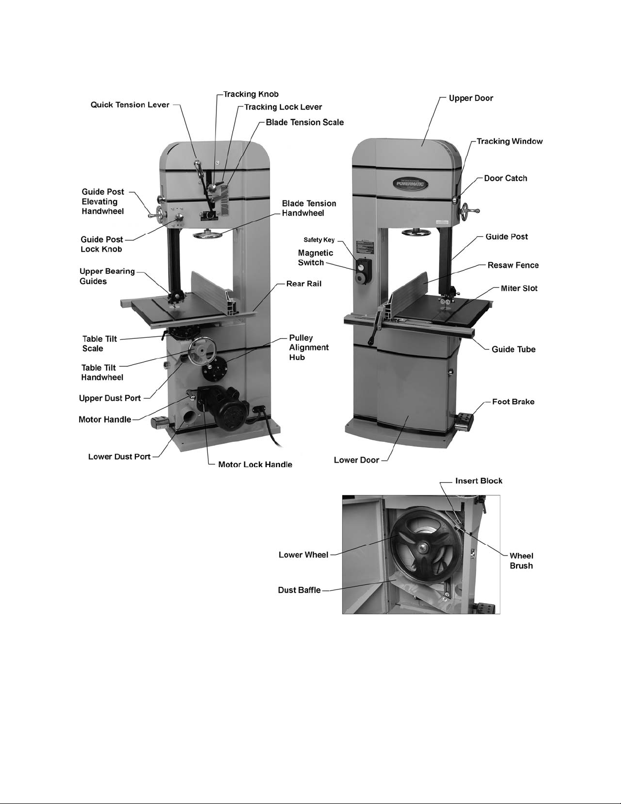
Features and Terminology
Figure 1
8
Page 9
Unpacking
Open shipping cont ainer and check f or shipping
damage. Report any damage immediately to
your distributor and shipping agent. Do not
discard any shippi ng material until the Band Saw
is assembled and r unning pr oper ly.
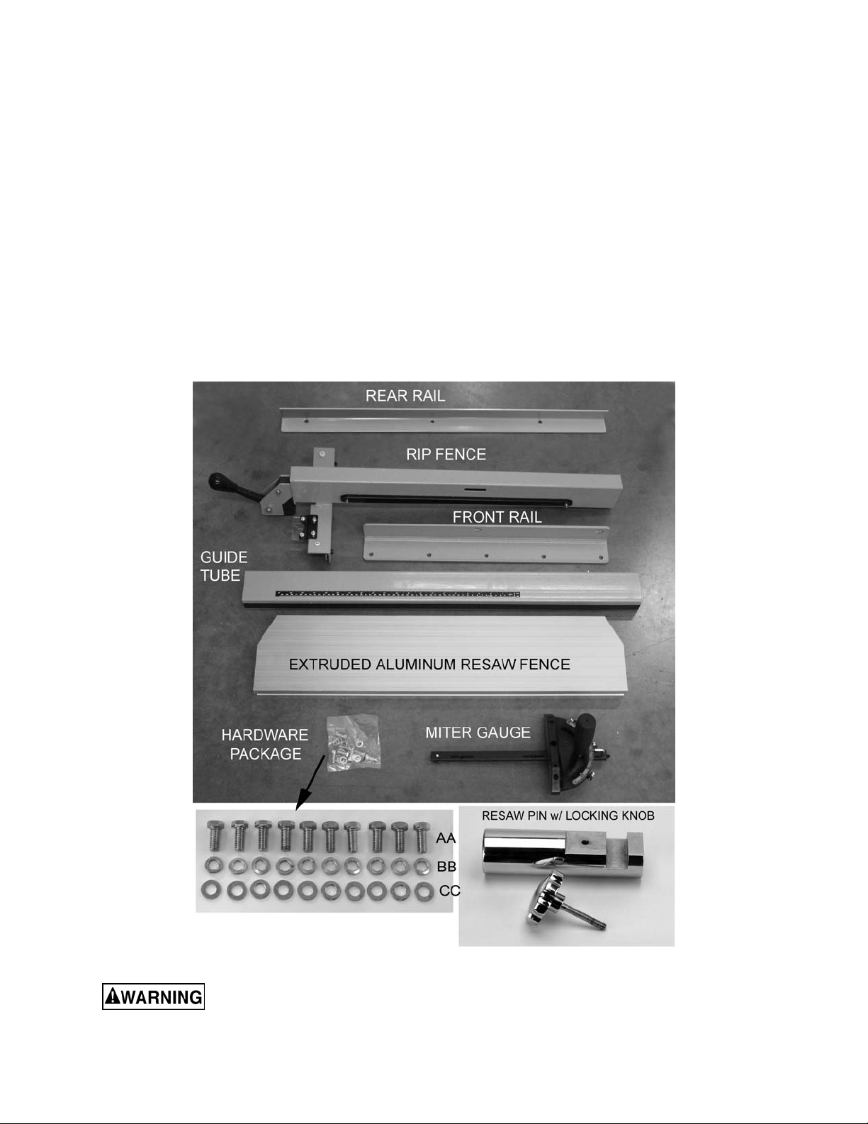
Compare the c ontent s of y our cont ainer wit h t he
following parts list and photos to make sure all
parts are intac t. Missing part s, if any, shoul d be
reported to your di stributor. Read the instruct ion
manual thoroughly for assembly, maintenance
and safety instruc tions.
Contents of the Shipping Container
1 Band Saw (not shown)
1 Rip Fence Body
1 Extruded Aluminum Resaw Fence
1 Front Rail
1 Rear Rail
1 Guide Tube
1 Resaw Pin with Locking Knob
1 Hardware Package cont aining:
10 Hex Cap Screws, 5/16”-18 x 3/4” (AA)
10 Lock Washers, 5/16” (BB)
10 Flat Washers, 5/16” (CC)
1 Miter Gauge
1 Owner's Manual (not shown)
1 Warranty Car d (not shown)
Figure 2
Read and understand the entire contents of this manual before attempting set-up
or operation! Failure t o co mply may cause serious injury.
9
Page 10
Installation
Tools requi red for assemb ly and set up:
7/32” hex (Allen) wrench
6mm hex (Allen) wrench
12mm open-end wrench
Square
Hoist or forklift, with straps
Remove all crati ng and plastic from around the
machine. Remov e any screws or straps hol ding
the band saw to the shippi ng pallet.
Exercise care when
removing the machine from the shipping
pallet.
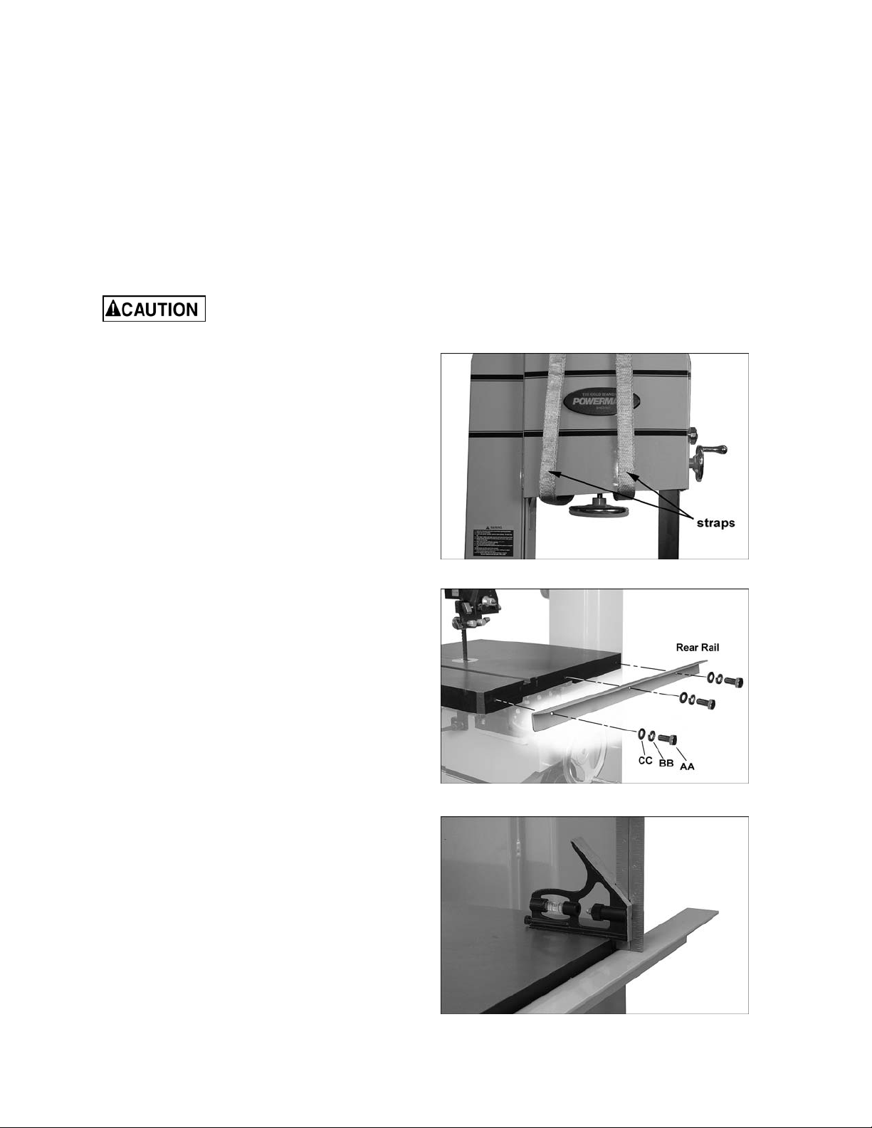
Use a hoist or f orklift with straps to rem ove the
machine fr om the pallet. The straps used shoul d
have a minimum 1,000 lb. lifting capacity. Do
NOT place forks or straps directly beneath the
table or against handles or levers - place the
straps under the top portion of the frame, as
shown in Figure 3.
Move the band saw to its permanent location,
which should be dry and well lit, with enough
space on all sides to handle long stock or
perform routine maintenance on the machine.
Make sure the fl oor is able to support t he weight
of the machi ne. If desired, the band saw can be
secured to the floor using lag screws (not
provided) t hr ough the four holes in the base.
Exposed metal surfaces, such as the table
surface and blade guides, have been given a
protective coating at the factory. This coating
should be rem oved wit h a soft c loth moistened
with solvent . Do not get solvents near pl astic or
rubber parts; and do not use an abra siv e pad as
it may scratch the exposed surfaces.
Assembly
Rear Rail
Refer to Figures 4 and 5.
1. Install the rear rail to the rear edge of the
table, using three 5/16-18 x 3/4 hex cap
screws (AA), three 5/16 lock washers (BB),
and three 5/16 f lat washers (CC) as shown.
Hand tighten only .
Figure 3
Figure 4
2. The exact distance from rear rail to table top
is not important , but the rear rail should be
made parallel to the table top. Place a
measuring device, such as a combination
square (Figure 5) at front and back of the
table as shown.
Figure 5
10
Page 11
The measurement should be the same at
both ends of the rear rail. Adjust as needed.
3. Tighten the three screws with a 12mm
wrench.
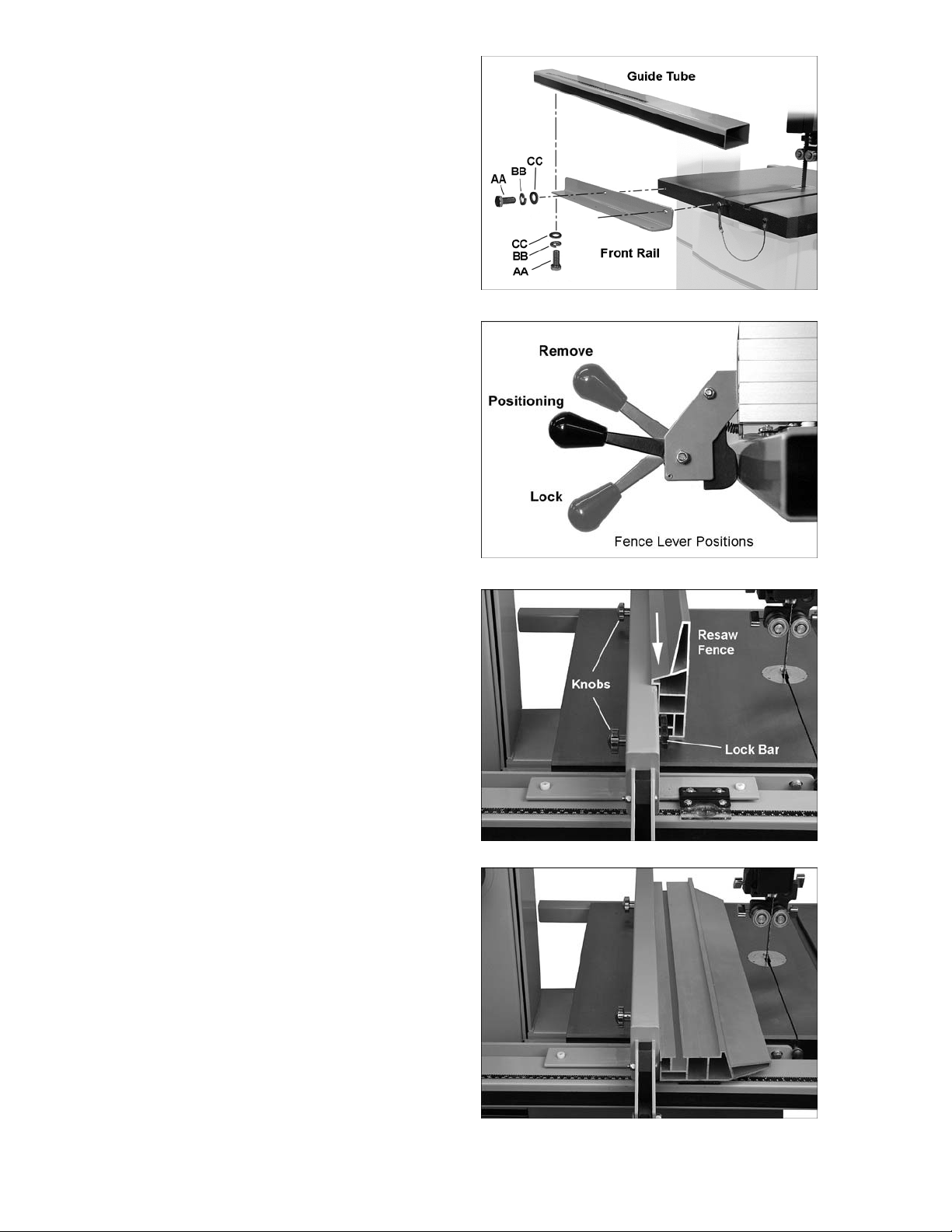
Front Rail and Guide Tube
Refer to Figure 6.
4. Install the front rail t o the front edge of the
table, using two 5/16-18 x 3/4 hex cap
screws (AA), two 5/16 lock washers (BB),
and two 5/16 f lat w ashers (CC), through t he
slotted holes in the rail. Place the screws
approximately center of the slots; this can
be adjusted later as needed. Tighten the
two screws with a 12mm wrench.
5. Install the guide tube to the bottom holes in
the front rail, using five 5/16-18 x 3/4 hex
cap screws (AA), five 5/16 lock washers
(BB), and five 5/16 flat w ashers (CC) . Hand
tighten only. Pull the guide tube away from
the table as far as it will go, then tighten all
five screws in the guide tube with a 12mm
wrench. Do not overtighten.
Figure 6
Figure 7
Fence Assembly
Refer to Figures 7 and 8.
Place the fence body onto the guide tube (as
shown in Fi gure 8). Rai se the fence l ev er all the
way up to install or remove the fence from the
guide tube. Midway lever position allows the
fence to slide along the gui de tube. Lowest lever
position locks the fence in place.
Resaw Fence
Refer to Figures 8 and 9.
Loosen the lock bar using the knobs, until the
lock bar protrudes enough to sl ide t he al uminum
resaw fence on from one end, as shown in
Figure 8. Re-ti ghten the knobs.
NOTE: The aluminum resaw fence can be
installed in one of two positions; vertically
(resaw position), as shown in Figure 8; or
horizontally as shown in Figure 9. Horizontal
position is useful for smaller workpieces. (The
zero setting of the cursor cannot be used with
the horizontal fence position.)
Figure 8 (resaw f enc e vert ic al pos ition)
Figure 9 (horizontal fence posit ion)
11
Page 12
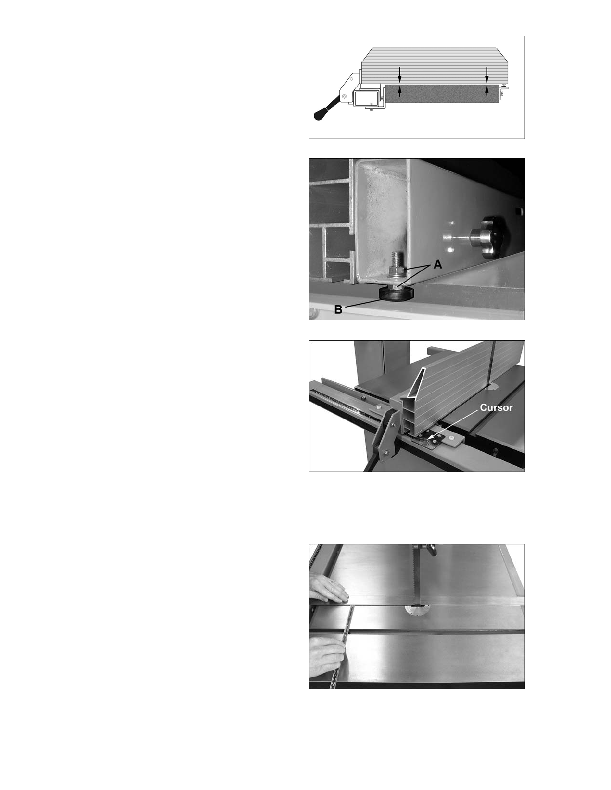
Fence to Table Clearance
1. Check the cl earance between the table and
the bottom of the fence (Figure 10). The
fence should not rub against the table
surface but be slightly above it. This gap
should be the sam e at the front of the tabl e
as it is at the back.
2. If the clearance is not the same, use a
combination of the following two
adjustments:
• With a 7/32” hex wrench, rotate the two
nylon adjustm ent screws (A, Figure 16) t he
same amount to raise or lower the fence
body from the guide tube. Clockwise rai ses
the fence body, count er c lockwise lowers.
• And/or....A djust the back end of the fence
by loosening one hex nut and tight ening the
other (A, Figure 11) in order to raise or
lower the sliding pad (B, Figure 11) as
needed. When the fence-to-table gap is
equal, make sure both hex nuts are
tightened against the fence body.
Setting Cursor (Zero) Position
Figure 10
Figure 11
Refer to Figure 12.
The fence must be set so that the cursor reads
zero at the line of the blade. The resaw fence
must be installed on the f ence body in vertical
position, and the blade must be installed and
fully tensioned.
1. Slide the fence flush against the flat of the
blade, as shown. (Do not force the fence
into the blade so that t he blade bends.)
2. If the cursor is not at zero, loosen the t wo
screws and slide it as needed. Then retighten the screws.
Setting Table Parallel to Blade
Refer to Figures 13 and 14.
The table has been al i gned by t he m anuf act urer
so that the miter slot is parallel to t he flat of the
blade; it should not require adjustment.
However, i n the future y ou may wish to conf irm
this setting is still accurate. A wide blade is
recommended for the procedure.
1. Disconnect band saw f r om power source.
Figure 12
2. The blade should be fully tensioned and
properly t r acked (see pages 17 and 18).
3. Place a long straightedge flush against the
blade making sure it cont acts both front and
back of the bl ade. (Do not deflect the blade
by pushing into it. ) See Figur e 13.
Figure 13
12
Page 13
4. Use a gauge to carefully measure the
distance from miter slot to straight edge.
Take measurem ents at both front and back
of table – these should be the same.
5. If t he miter slot is not parallel to t he blade,
loosen the four hex cap screws that secure
the table to the trunnion (Figure 14 shows
three of them), and shift the table as needed
until the miter slot is parallel to the blade.
6. Tighten the four hex cap screws.
Setting Fence Parallel to Blade
Refer to Figures 15 and 16.
The fence should be parallel to the flat of the
blade for accurate cutting. Since the miter slot
has been set parallel to the blade from the
manufacturer (and confirmed by the user, as
described above), you can use the table miter
slot to set the fence par allelism.
1. Remove the alumi num resaw fence and the
mounting bar f rom the f ence body, and sli de
the fence body t o the edge of the mi ter slot,
as shown in Figure 15. The fence should
align with the miter slot along the entire
length of the f enc e.
Figure 14
2. If adjustm ent is needed, use one of the back
adjustment sc rew s (B, Fi gure 16) t o tur n the
fence in line wit h the miter slot.
The fence must also be parallel to the blade
vertically. Refer to Figure 17.
3. Make sure t he tabl e ha s been set 90° t o the
blade (see “90° Table Stop”).
4. Mount the resaw fence, and slide the fence
up against the blade; do not push into the
blade. Turn either of the nylon adjustment
screws until fence is parallel to blade along
the vertical length of fence.
Fence Locking Tightness
The tightness of the fence against the guide
tube can be adjusted by rotating the two back
screws (B, Figure 16). Rotate the two screws
equally (clockwise to tighten) with a 5mm hex
wrench.
Because these screws are also used to align the
fence to t he blade, aft er adjusting f ence locking
tightness, you should double check fence-toblade relationship, as explained under “Setting
Fence Parallel to Blade.”
Figure 15
Figure 16
Figure 17
13
Page 14

Dust Collection
The use of a du st collection system is strongly
recommended for this band saw. It will help
keep the shop clean, as well as reduce pot enti al
health hazards caused by inhalation of wood
dust. The collector should have a capacity
sufficient for this size machine – 400 CFM is
recommended. Walter Meier has a line of dust
collection system s available; see your dealer or
visit our website li sted on the back cover.
Connect the hoses of your dust collection
system to the 4” dust ports at the rear of the
band saw. Secure ti ghtly with hose clamps (not
provided). S ee Figure 18.
Figure 18
Electrical Connections
Electrical connections must
be made by a qualified electrician in
compliance with all relevant codes. This
machine must be properly grounded to help
prevent electrical shock and possible fatal
injury.
Single Phase Connections
The single phase B and Saw is fact ory wired for
230 volt s. It is not supplied with a plug. Y ou may
either install a UL/CSA-listed plug suitable for
230 volt operati on, or “hard-wire” the B and Saw
directly to a service panel.
It is recommended that the single phase Band
Saw be connected to a grounded and dedi c ated,
minimum 50 amp circuit with a 50 amp circuit
breaker or time delay fuse. Local codes take
precedence o ver recommendations.
Three Phase Connections
The three phase Band Sa w is fact ory wired for
230 volt s. It is not supplied with a plug. Y ou may
either install a UL/CSA-listed plug suitable for
230 volt operati on, or “hard-wire” the B and Saw
directly to a service panel.
The three phase Band Sa w m ay be c onverted t o
460V operation. The current contactor m ust be
replaced with t he 460V magnetic contac tor (part
no. PM2000-293C, purchased separately). In
addition, re-connect the motor leads according
to the diagrams inside the motor junction box.
(Similar di agrams may be found at t he back of
this manual.)
It is recommended that the three phase Band
Saw be connected to a grounded and dedi c ated,
minimum 30 amp circuit with a 30 amp circuit
breaker or time delay fuse. Local codes take
precedence o ver recommendations.
If the single phase or t hree phase Band Saw is
to be “hard- wired” t o a serv i ce panel , m ake sure
a disconnect i s availabl e for the operator . During
hard-wiring of t he machine, make sure t he f uses
have been rem oved or the breakers hav e been
tripped i n the circuit to which the Band Sa w will
be connected. Place a warning placard on the
fuse holder or circuit break er to prevent it being
turned on while t he machine is being wired.
Grounding Instructions
This machi ne must be grounded. In the ev ent of
a malfuncti on or breakdown, grounding prov ides
a path of l east resistance for elect ric current to
reduce the ri sk of el ectri c shock .
Improper connection of the equipmentgrounding conductor can result in a risk of
electric shock. The conductor with insulation
having an outer surface that is green with or
without yellow stripes, is the equipmentgrounding conduct or .
If repair or replacement of the electric cord or
plug is necessary, do not connect the
equipment-grounding conductor to a live
terminal.
Check with a qualified electrician or service
personnel if the grounding instructions are not
completely understood, or if in doubt as to
whether the tool i s properly gr ounded. Repai r or
replace a damaged or worn cord im m ediately.
Make sure the voltage of your power supply
matches the specif ications on the m otor pl ate of
the Band Saw.
14
Page 15
Extens ion Cords
The use of extension cor ds i s di scouraged; try to
position t he machine within reach of the power
source. If an extension cord becomes
necessary, m ake sure the cord rati ng is suitable
for the am perage listed on t he machine’s m otor
plate. An undersized cord will cause a drop in
line voltage resulting in loss of power and
overheating.
Recomm end ed Ga ug es (A WG ) of Extensi on Co rd s
Extension Cord Length *
25
50
75
100
150
200
Amps
< 5 16 16 16 14 12 12
5 to 8 16 16 14 12 10 NR
8 to 12 14 14 12 10 NR NR
feet
feet
feet
feet
feet
feet
Use the chart i n F igur e 19 as a gener al gui de i n
choosing the c orrect size cord. If in doubt, use
the next heavi er gauge. The smaller the gauge
number, the heavier the cord.
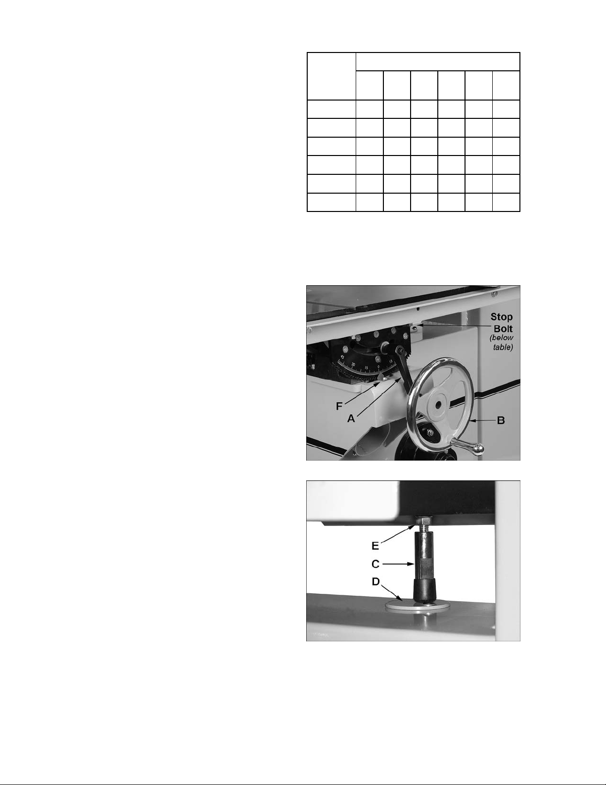
Adjustments
Table Tilt
Refer to Figures 20 and 21.
1. Loosen the lock l ev er (A).
2. For right tilt (as viewed from front or
operator’s side of the saw), rotate the
handwheel (B) count erclockwise to ti lt table
up to 45°.
3. For left tilt (as viewed from front or
operator’s side of the saw), loosen the l ock
lever (A) and rotate the handwheel
clockwise a turn or two to release pre ssure
on the 90° stop bolt (C). Rot ate the circular
plate (D) out of the way. Then rotate the
handwheel cloc k wise to tilt the table to 15°.
The now-exposed hole in the band saw
body allows the stop bolt to descend
through it, to keep intact the setting of the
90° stop.
12 to 15 12 12 10 10 NR NR
15 to 20 10 10 10 NR NR NR
21 to 30 10 NR NR NR NR NR
*based on li miting th e lin e voltag e drop t o 5V at 150% of the
rated amp eres.
NR: Not Recommended.
Figure 19
Figure 20
4. Tighten the lock lever (A, Figure 20) to
secure the setting.
NOTE: The circular plate (D) can be tight ened or
loosened as desired by using a 5/ 32” (4mm ) hex
wrench on the screw.
Also, the lever (A, Figure 20) can be pivoted to a
more conveni ent positi on. Simply lift str aight out
on the lever and rotate it on the pin, then release
the lever making sure i t seats itself on the pin.
90° Table Stop
Refer to Figures 20 t hr ough 22.
The 90° positiv e stop ensures that the tabl e will
always be perpendicular to the blade after the
table is returned to horizontal position. Check
and adjust this 90° stop as follows:
1. Disconnect machine from power source.
2. Make sure blade is under f ull tension.
Figure 21
15
Page 16
3. Loosen lever (A, Figure 20) and tilt table
with the handwheel (B), until the stop bolt
(C) rests on the circular plate (D).
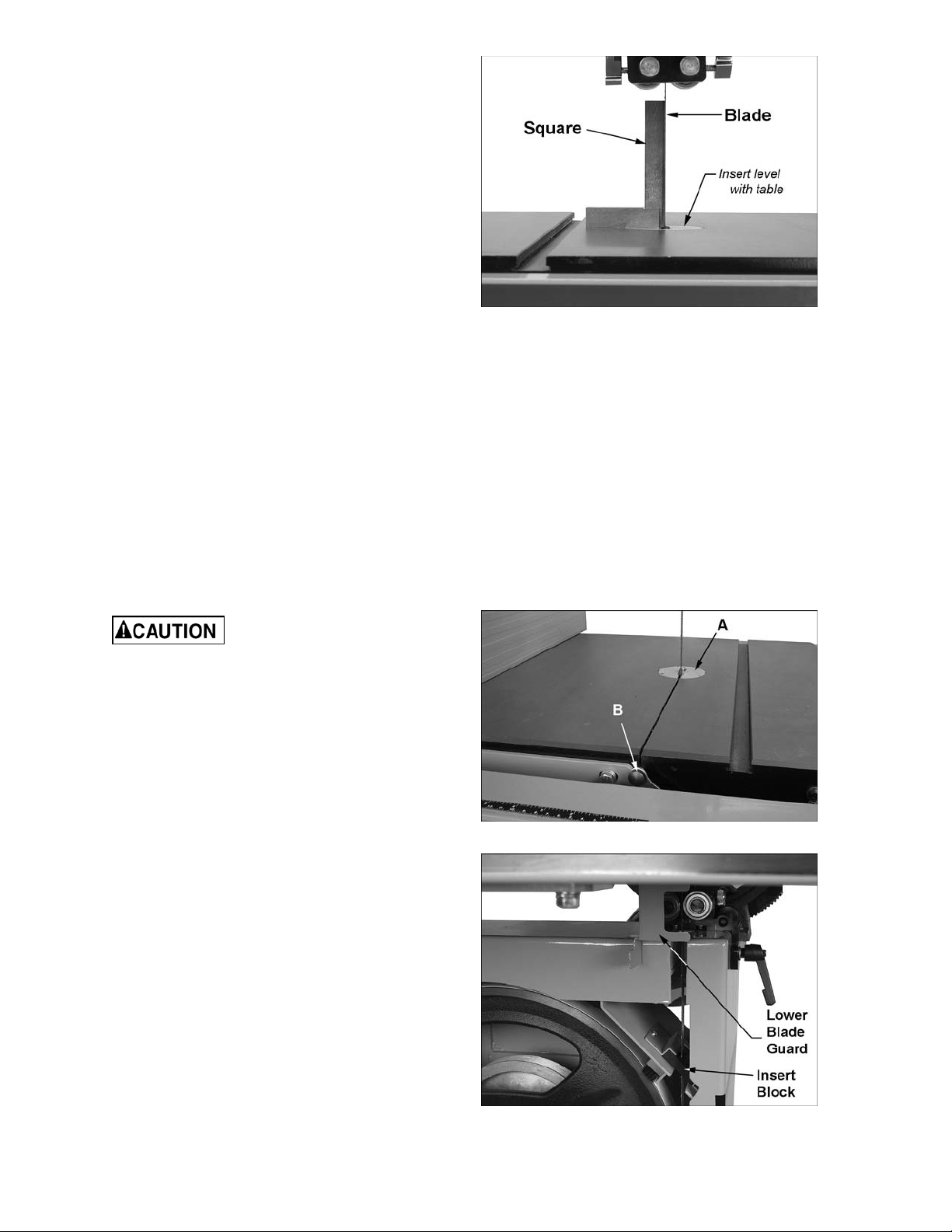
4. Make sure the table insert is level with
surface of table by rotating one or more of
its set screws with a 5/164” (2mm) hex
wrench. Then place a square on the table
and against the bl ade to check that the table
is 90° to the blade. See Figure 22. NOTE:
Do not push square into blade.
5. If table and blade are not square, use a
9/16” (14mm) wrench t o loosen the lock nut
(E) then rotate the stop bolt. Turn the stop
bolt as needed until there i s no longer li ght
showing between the square and the blade.
6. Tight en lock nut (E) to secure the table st op
in position.
7. Tighten the lever (B).
8. Check that the scale pointer (F, Figure 20)
is at zero. If nec essary, loosen the scre w on
the pointer and shift the pointer to zero.
Then re-tight en the screw.
Figure 22
Installing/Changing Blades
Always wear gloves when
handling blades. New blades are usually
packaged in a coiled position; to prevent
injury uncoil them slowly and carefully, while
wearing work gloves and safety glasses.
The PM1800 Band Sa w is designed f or blades
from 1/16” to 1-1/2” wide. The Band Saw is
provided with a blade of the following
specific ations: 0.03” thick, 3/4” wide, 4 TPI.
Refer to Figures 23 and 24.
1. Disconnect machine from power source.
2. Remove the table insert (A, Figure 23) .
3. Pull out table pin (B) at the end of the slot.
4. Adjust upper and lower blade guides away
from the blade.
5. Move the quick tension lever to “Full
Release (Blade Change)” posi tion.
6. Open upper and lower door s by rotati ng the
door catches. Open the lower blade guard
and slide out the i nsert bloc k (Figur e 24).
Figure 23
7. Carefully remove the blade from the top
wheel, then f rom between upper and lower
blade guides and lower wheel. S lide the old
blade out through the sl ot in the table.
Figure 24
16
Page 17

8. Guide new blade through table slot. Place
blade loosely in the upper and lower blade
guides. Make sure blade teeth point down
toward table, and toward the front of the
saw. (If the teeth will not point down, no
matter how you orient the blade, then the
blade is twisted inside-out. Twist it into
correct position and re-install it .)
9. Position blade at the center of the upper and
lo wer wheels.
10. Re-install table insert (A) and table pin (B).
11. Before operating the band saw, the new
blade must be tensioned and tracked, in that
order. Find instructions for tensioning and
tracking the blade under “Blade Tension”
and “Blade Tracking.” The blade guides
must also be set properly according to the
instructions on pages 19 and 20.
Blade Tension
Refer to Figure 25.
1. Disconnect machine from power source.
2. Back off upper and lower guide beari ngs to
eliminat e any contact with the blade.
3. With the blade centered on the wheels,
move the quick tension lever to “Full
Tension” position, as shown in Figure 25.
NOTE: You will be abl e to feel the lev er fall
into each position.
4. Rotate the tension handwheel (C) until the
scale pointer (D) reaches the appropriate
measurement f or the width of the blade.
TIP: Use the band saw’s gauge setting initi ally.
As you become familiar with the machine and
with the dif fer ent proper ti es of band saw bl ades,
you may find it necessary to change the blade
tension fr om the initi al setti ng. Keep in mi nd that
not only changes in blade width, but also the
type of materi al being cut will have an effect on
blade tension. Too little or too much blade
tension can cause blade breakage and/or poor
cutting perf ormance.
Make a note of the speci fic tension setti ng f or a
particular blade. The tension can t hen be re-set
quickly when band saw operations are resumed.
IMPORTANT: When the band saw is not bei ng
used, move the quick tension lever to “Partial
Tension-Idle/Tracking” position. This will prolong
the life of the blade and tires, and r educe load
on wheels, bearings and other c om ponents.
Figure 25
17
Page 18

Blade Tracking
Refer to Figure 26.
After being properly tensioned, the blade must
be tracked. “Tracking” refers to the position of
the blade on t he wheel s while t he machi ne is in
operation. Tracking should be checked
periodical ly, and is mandatory after every blade
change. Blade t rack ing is done by ha nd with t he
machine disconnected from power.
1. Disconnect machine from power source.
2. The blade should be cor r ectly tensioned.
3. Make sure the blade gui des and other parts
of the machine will not interfere with the
movement of the blade. Lower the guide
post until you can see t he bl ade throu gh t he
tracki ng window.
4. Set the qui ck tension l ever intially t o “Partial
Tension-Idl e/Tracking” posi tion, as shown i n
Figure 26.
5. Open upper door to expose the upper
wheel. Rotate the wheel by hand, and
observe the position of the blade on the
wheel through t he tracking window. As you
rotate the wheel, move the lever to “Full
Tension” position. The blade should
continue to ride upon the center of the
wheel (Figure 27) .
IMPORTANT: Make tracking adjustments with
knob (F, Figure 26) while the blade is at full
tension. DO NOT use screws (G, Figure 26);
these were used by the manuf acturer for wheel
alignment and should NOT be used for tracking.
6. If the blade tends to move toward the edge
of the wheel, loosen loc king lever (E, Fi gure
26) and slightly rotate tracking knob (F) with
your right hand while continui ng to rotate the
wheel with your left. Observe the blade
through the tracking window. Rotating the
tracki ng knob cl ockwise will cause the blade
to move t oward the rear edge of the wheel.
Rotating t he tracking knob count erclock wise
will cause the blade to move toward the
front edge of the wheel.
Figure 26
Figure 27
IMPORTANT: This adjustment is sensitive;
perform it in small increment s and give t he
blade time to react t o the changes.
7. When the bl ade is tracking in the cent er of
the wheel, re-tighten locking lever (E), and
close upper door.
8. Move tension lever to “Full Tension”
position, and connect the band saw to
power. Turn i t on f or a brief time to observ e
the blade in action through the tracking
win dow.
18
Page 19

9. Make further adjustments as needed, with
the saw disconnected from power.
Upper Blade Guides
The bearing guides should be set so that
contact between blade and guides will occur
only when the blade is under pressure from a
workpiece. To adjust the upper bearing guides
for proper bl ade c ontrol, proceed as follows.
Refer to Figures 28 t hr ough 31.
1. Disconnect machine from power source.
2. Blade must already be tensioned and
tracking c orrectly. Place quick tension lever
in “Full Tension” posi tion.
3. Lower the guide post until the upper guide
bearings are a f ew inches off t he table. (T he
reason for this will be shown later under
“Guide Post Parallelism.”)
4. Loosen the locki ng screw (A, Figure 28).
5. Move the entire guide bracket by rotating
the knurled knob (B) until the front of the
guide bearings are about 0.015” (1/64”)
behind the blade’s gul let (curv ed area at the
base of the tooth). See Figure 30.
6. Tighten t he locking screw (A) to secure this
position.
7. Loosen the lock ing screw (C) for one of the
guide bearings.
8. The guide bearing rotates on an eccentric
shaft. Adjust the guide bearing by rotating
the knurled k nob (D) until the guide bear ing
is approximately 0.004” from the blade. A
quick way to achieve this spacing is by
placing a single thickness of a crisp dollar
bill (a dollar bill is approximately 0.004”
thick) between blade and guide bearing.
See Figure 31. Adjust the guide bearing
until it just lightly grips the dollar bill.
NOTE: Do not force the guide bearing
against the side of the blade. It should only
make contact with the blade when there is
pressure from the cutti ng oper ation.
Figure 28
Figure 29
Figure 30
9. Ti ght en locking screw (C) and remove dollar
bill.
10. Repeat process for opposite guide bearing.
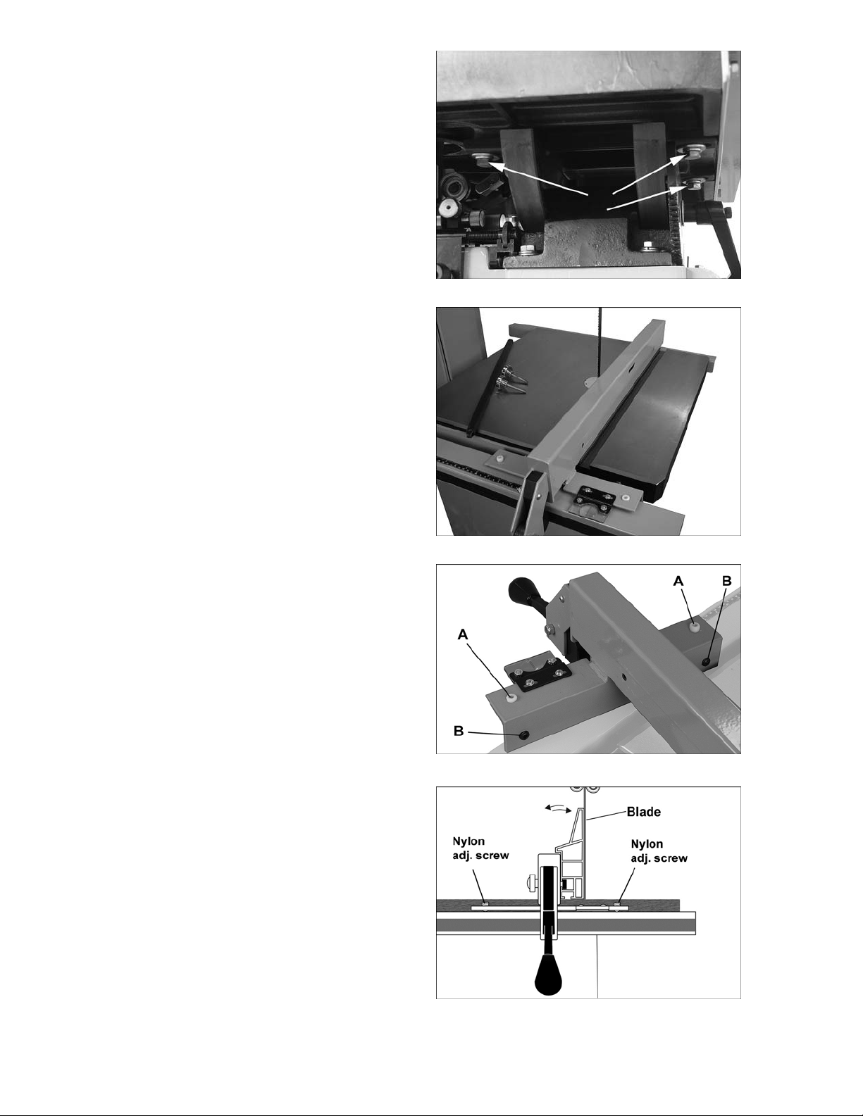
Upper Thrust Bearing
Refer to Figures 29 and 32:
The thrust beari ng prev ent s backward def l ecti on
of the blade during cutting. The thrust bearing
has three options for stabilizing the back of the
blade (see Figur e 32) .
Figure 31
19
Page 20

v
-
shaped groove is f or blades 1/8” wide or
The
smaller. The flat bottomed groove supports
blades over 1/ 8” to 3/16” wide. The non-grooved
standard bearing surf ace at the left is for blades
over 3/16” wide. (The bl ade provided with your
band saw is 3/4” wide, t hus must ride along t he
flat non-grooved surface of the bearing, as
shown in Figure 32.)
1. Loosen the socket head cap screw (E,
Figure 29) and push the thrust bearing
bracket later ally to desired position.
2. Re-tighten the socket head cap screw (E).
3. Loosen the l ocking screw (F) and push the
thrust bearing up to the back of the blade.
4. Adjust the thrust bearing until the space
between the thrust bearing surface (or
groove bottom) and the back edge of the
blade is approximately 0.015” (1/64”). On
the non-groov ed surface, a conv enient way
to achieve t his spacing i s by placi ng a dol l ar
bill folded t wice (four thick nesses of a doll ar
bill is approximately 1/64”) between blade
and thrust bearing. If using a groove, set
this distance by ey e.
5. Tighten loc ki ng screw (F) .
6. Make sure all locking screws on the upper
guide bearing assembl y are tightened when
adjustments are finished.
Lower Blade Guides
Refer to Figure 33.
1. Disconnect band saw f r om power source.
2. Open lower door and lower bl ade guar d.
3. Adjust the lower guide bearings and lower
thrust bearing below the table, using the
same procedure and measurements as for
the upper guide bearings and upper thrust
bearing described above.
Figure 32
Movement summary: Loosen locking lever
(G) to move guide bracket using dial (H).
Loosen knob (J) to rotate side bearings,
using (K) and (L). Loosen locking screw (M)
to slide thrust bearing toward blade.
4. Make sure all screws, knobs and lever are
tightened when adjustments are complet e.
NOTE: The locki ng lever (G, Figure 33) c an be
re-positioned if needed. Simply pull out on the
lever, r otate it on the hub, and release it. Mak e
sure it re-seats itself on the hub.
Figure 33
20
Page 21

Guide Post
Refer to Figure 34.
1. Disconnect band saw f r om power source.
2. Loosen lock handle (A) and raise or lower
guide post by rotating the handwheel (B).
3. Position the blade guide assembly so that
the bottom of the guide beari ngs are about
3/16” above the material to be cut. Or,
simply lower the guide post until the scale
pointer (C) indicates the height of your
workpiece. Thi s provides minimal clearance
between the workpiece and the bottom of
the guide bearings, which will minimize
blade deflection as well as enhance
operator safety.
4. Tighten loc k handl e ( A).
Guide Post Parallelism
The guide post should be parall el to the blade
throughout the v ertical travel of the guide post;
thus the guide bearings will maintain their
relationship t o the blade at any height from the
table and they won’t hav e to be re- set each tim e
the guide post i s moved. Thi s setting has been
accurately made by the manufacturer and
should not require immediate attention, but it
may be checked in the fut ur e as follows:
1. Disconnect band saw f r om power source.
2. Move blade tension lever to “Full Tension”
position.
3. The guide bearings in low position should
already be set in relation to t he blade (see
“Upper Blade Guides”). Also, the table
should be square with the blade (See “90°
Table Stop”).
4. Loosen the lock handle (A, Figure 34) and
raise the guide post to a high position.
5. Confirm that the guide post travels straight
up and down, and the guide bearings
maintain t heir r elationship to the blade.
6. If the guide post does not go strai ght up and
down (the blade begi ns deflecti ng when the
guide post is rai sed), sli ghtl y loosen the four
hex cap screws (D, Figure 34).
Figure 34
7. Left and right adjustment is accomplished
using a combination of the four hex cap
screws (D); forward/back adjustment is
accomplished using the two set screws (E).
8. When finished adjusting, securely tighten
the four hex cap screws (D).
9. Re-check the setting by raising and lowering
the guide post.
21
Page 22

Resaw Pin
Refer to Figure 35.
A resaw pin is provided with the band saw. It
provides a single contact point while ripping a
workpiece int o thinner boards.
Remove the al uminum resaw fence and mount
the resaw pin to the slot in the fence body,
securing it with the knob, as shown. The resaw
pin is usually positioned so that its center is
approximately even with the front edge of the
blade.
See under “Operat ion” for further inf ormation on
using the resaw pin.
Miter Gauge
Refer to Figures 36 and 37.
A miter gauge is provided for crosscutting
operations. I nstall the miter gauge by sliding t he
end of the miter gauge bar into the table’s T-slot.
The miter gauge should fit snugly within the
miter slot whil e still sliding easi ly. The bar of the
miter gauge has two sl ots, each with a set screw
(Figure 36). Rotate one or both of these set
screws with a 5/32” (4mm) hex wrench as
needed to elimi nate any play bet ween the miter
gauge bar and miter slot .
If the tabl e/miter slot is square to t he blade (see
“Setting Table Parallel to Blade”), the miter
gauge will also be square to the blade. Before
operating, howev er, the 90° setti ng of the miter
gauge should be checked in relation to the
blade, as follows.
Figure 35
Figure 36
1. Place a square against the miter gauge
face, and against the flat of the blade, as
shown. (Place t he square against the fl at of
the blade, not the teeth which are set wider
than the blade body). A wide blade is
preferred for this procedure.
2. Flip the 90° stop plate (C) out of the way,
and loosen the handle (A). Shift the miter
gauge body unti l it is flush with t he square,
then re-tight en the handle (A).
3. Flip the stop plate (C) back down, and
loosen the 90° stop hex nut and adjust the
screw until it c ontacts the 90° stop plate.
4. Re-tighten hex nut.
5. Loosen the set screw at the base of the
pointer, and shi ft the poi nter so that it l ines
up with the 90° mark on the scale.
6. Re-tighten set screw.
Figure 37
22
Page 23

The 45° stops can be check ed in similar fashion,
using an angle gauge similar to that shown in
Figure 37.
To adjust the miter gauge angle for operations:
1. Loosen the handle (A ) .
2. Rotate t he gauge body until the pointer (B)
lines up wit h the desi red an gle on t he scale.
You may have to pivot the 90° stop plate (C)
out of the way to allow the body t o rotate.
3. Tighten the handle (A).
4. There are three stops – at 90° , and 45° lef t
and right. E ach of these can be a djusted by
loosening the hex nut (D) and turning the
screw (E) as needed. Re-ti ghten the hex nut
(D) when adjustment is finished.
Blade Speed Adjustment
Refer to Figures 38 t hr ough 40.
The band saw will operate at 1800 and 4200
SFPM (surface feet per minute). Figure 39
shows the appropriate belt position to achieve
each speed.
To change the speed:
1. Disconnect machine from power source.
2. Loosen the motor lock handle and r aise the
motor lift handle to release tension on the
belt.
3. Tighten the motor lock handle to k eep motor
in raised positi on.
4. Slide the belt onto the appropriate set of
pulle y s.
5. Loosen motor lock handle and allow motor
to lower. The weight of the motor itself
should produce the proper tension for the
belt. Check the tension by pushing with
moderate pr essure against the cent er of the
belt (Figure 40). An adequately tensioned
belt will deflect about 1/2”. If tension isn’t
strong enough, push down on the motor.
Figure 38
Figure 39
6. Tighten the motor lock handle.
Drive Belt Tension and Replacement
The drive bel t and pul leys are properl y adjusted
at the f actory. Howev er, belt tension should be
occasionally checked when the band saw is
new, as a new belt may stretch slightly during
the breaking-i n pr oc ess.
If the belt becomes worn, cracked, frayed or
glazed, it should be replaced as follows:
Refer to Figures 38 and 40.
1. Disconnect machine from power source.
Figure 40
23
Page 24

2. Open the upper and lower doors and
remove the blade.
3. Unscrew the hex nut from the lower wheel
shaft and remove the lower wheel.
4. Loosen the mot or lock handle.
5. Raise the motor lift handle and re-tighten
motor lock handle to hold motor in raised
position.
6. Remove old belt and install new one,
making sure it seats properly in the pulley
grooves.
7. Loosen motor lock handle and allow motor
to lower.
8. The weight of the motor itself should
generally pr oduce the proper t ension for t he
belt. Check the tension by pushing with
moderate pr essure against the cent er of the
belt (Figure 40). An adequately tensioned
belt will deflect about 1/2”. If tension isn’t
strong enough, push down on the motor.
9. Tighten motor lock handle, reinstall lower
wheel, and instal l hex nut securely on shaft.
10. Re- check blade tensi on and tracki ng before
operating the saw.
Wheel Brush
Refer to Figure 41.
The brush located nex t to the lower wheel must
contact the tire to clear the tire of dust and
debris befor e it touches the blade. Use the two
phillips head screws to make any adjustments to
the brush position.
Insert Block
Refer to Figure 41.
The insert block should remain in position to
prevent dust and chips from falling onto the
lower wheel. If it should ever become dam aged,
it should be replaced. Some band saw users
make their own out of scrap wood.
Operating Controls
Start/Stop
Power Indicator Light – The start switch has a
power indicator lamp which is on whenever
there is power connected to the Band Saw,
not just when the B and Saw is running. Do not
assume that no light means there is no power to
the machine. I f the bul b is bad, there will be no
indication. Always check before use.
Figure 41
24
Page 25

Do not rely that no light
means no power to the machine. Always
check for pow er first. Failure to comply may
cause serious inj ury!
Refer to Figure 42:
Start – Press the green start switch.
When power is connected to the machine, the
green light is always on regardless of whether
the Band Saw is running or not.
Stop – Press the red switch to stop.
Reset – In the event that the Band Saw stops
without pressing t he stop butt on, as the re sul t of
a tripped fuse or ci rcuit br eak er , etc.:
1. Press red button to re-set m ain switch.
2. Press the green button to restart the
machine.
Safety Key
The start/stop switch on the Band Saw comes
equipped with a magnetic safety key. When in
place on the switch as shown in Fi gure 42, the
magnetic safet y key trips a relay which will all ow
the machine to start and stop when the
respective switches are pressed. Being
magnetic, the lock can be r emoved t o make t he
machine inoperabl e and can be hidden for safe
storage by attaching it to another magnetic
surface.
When using the Band Saw, pl ace the key on t he
switch cov er lini ng up the arro w on the k ey with
the REMOVE arrow on the cover. Then rotate
the key so that t he ar r ow lines up wit h the LOCK
arrow on the cover. This will prevent the safety
key from coming l oose from vibrati on when the
machine is in use.
Figure 42
Brake Pedal
When the stop button is used to shut off the
Band Saw, the blade will coast sl owly to a stop
(approximat ely 12 to 15 seconds). An alternate
method of stoppi ng the machine is to press the
brake pedal, sho wn in Figure 43. The bl ade will
stop moving approximately four seconds after
the brake pedal i s pressed. Re-start the sa w by
pressing the start button on the column.
NOTE: Unnecessary and excessive use of the
brake pedal may shorten the life of the brake
band and brake belt.
After th e machi ne i s shu t o ff,
allow the wheels and blade to come to a
complete stop before opening the doors,
making adjustments, or leaving the area.
Figure 43
25
Page 26

Operation
The following sect ion contains basic information,
and is not intended to cover all possible
applicati ons or techniques using t he Band Saw.
Consult published sources of information,
acquire formal training, and/or talk to
experienced Band S aw users to gai n prof ici ency
and knowledge of band saw operations.
General Procedure
Ripping
Ripping is cutting lengthwise down the
workpiece, and with the grain (of wood stock).
See Figure 44. Always use a push stick or
similar device w hen r ipping nar r ow pieces.
Crosscutting
Crosscutting is cutting across the grain of the
workpiece, while using the miter gauge to feed
the workpiece i nto the blade.
1. Make sure the blade is adjusted correctl y for
tension and tracking, and that upper and
lower guide bearings and thrust bearings
are set in proper relation to the blade.
2. Adj ust gui de post so that t he guide be ari ngs
are just abov e the workpiece (about 3/16”)
allowing minim um ex posure t o the blade.
3. If using the fence, move it into positi on and
lock it to the gui de rail. If you are using the
miter gauge f or a cr osscut, the f enc e should
be moved safely out of the way.
4. Turn on the band saw and allow a few
seconds for t he machine to reach full speed.
Whenever possible, use a
push stick, hold-down, power feeder, jig, or
similar device wh il e f eeding stock, to preven t
your hands getting too close to the blade.
5. Pl ace the straightest edge of the workpiece
against the fenc e for a rip cut; or agai nst the
miter gauge for a crosscut. Push the
workpiece slowly into the blade, while also
keeping it pressed agai nst the f ence or held
against the miter gauge. Do not force the
workpiece int o the blade.
The right hand shoul d hold the workpiece steady
against the miter gauge, while the left hand
pushes the miter gauge past the blade, as
shown in Figure 45.
Do not use the fence in conjunction with the
miter gauge. The offcut of the workpiece must
not be constrained during or after the cutting
process.
Using the fence in
conjunction with the miter gauge can cause
binding and possible damage to the blade.
Some further operat ing tips:
Make relief cuts whenever possible. A relief cut
is an extra cut made through t he waste portion
of a workpiec e up to the layout l ine. When that
intersection is reached by the blade while
following the layout line, the waste portion
comes free. This helps prevent pinching of the
back edge of the blade in t he cut.
When cutting, do not
overfeed the blade; overfeeding will reduce
blade life, and may cause the bl ade to break.
When cutting long stock, the operator should
use roller stands, support tabl es, or an a ssistant
to help stabilize the workpiece.
Figure 44
Figure 45
26
Page 27

Resawing
Resawing is the process of slicing stock to
reduce its thickness, or to produce boards that
are thinner t han the original workpiece, such as
veneers.
The ideal blade for resawing is the widest one
the machine can handl e, as the wider the blade
the better it can hold a str aight line.
Resawing can be performed using the aluminum
resaw fence or the resaw pin. When using the
resaw fence, use a push block, push stick, or
similar device to keep your hands away from the
blade. The resaw pin offers a pivot point by
which you can caref ul ly f ollow your l ayout line; it
is especiall y useful for sawing curv es, when the
fence can’t be used and it’s difficult to control
the cut freehand.
Figure 46 demonstrates resawing with the
aluminum resaw fence; Figure 47, with the
resaw pin.
Blade Lead
Blade lead, or drift, is when the blade begins to
wander off t he cutting line even when the band
saw fence is being used. Figure 48 shows an
example of blade lead. It is m ore common with
small, narrow blades, and is almost always
attributable to poor blade quality, or lack of
proper adjustments. Inspect the band saw for
the following:
Figure 46
Figure 47
• Fence is not parallel to miter slot and blade.
• Blade is not tensioned c or r ec tly.
• Blade is dull.
• Teeth have too much “set” on one side of
the blade.
• Workpiec e is bei ng fed t oo quic kl y.
If the blade is suspect, but replacing it is not
currently an option, the blade lead can be
temporarily compensated for by skewing the
fence:
1. Cut a scrap pi ece of wood about the sam e
length as the band saw table, and joint one
edge along its length, or rip it on a t able saw
to give it a straight edge.
2. Draw a line on the board parallel with the
jointed, or str aight edge of the board.
3. Move the band saw fence out of the way,
and carefully make a freehand cut along
your drawn line on the board. Stop about
midway on the board, a nd shut of f t he band
saw (allow the bl ade t o come t o a compl ete
stop) but do not all ow the board to move.
4. Clamp the board to the table.
Figure 48
5. Slide the band saw fence over against the
board until it contacts the straight edge of
the board at some point. Lock the fence
down.
6. Use the back adj ustment scr ews (B, Figure
16) to line up the fenc e against the board.
7. Re-tighten the four hex cap screws.
NOTE: Skewing the f ence to correct blade lead
is effectiv e for that particular blade; when a new
blade is installed, the fence will need readjustment and re-squaring to miter slot. See
appropriate section in this manual.
27
Page 28

Maintenance
Before doing maintenance
on the machine, disconnect it from the
electrical supply by pulling out the plug or
switching off the main switch! Failure to
comply may cause seriou s injury.
Clean the band saw regularly to remove any
resinous deposits and sawdust.
Keep the miter slot, and the guide bearings,
clean and free of resi n.
Keep the blade clean and sharp. Check it
periodical ly for cracks or other signs of wear.
The drive bel t should be chec ked peri odicall y. If
it looks worn, frayed, glazed or otherwise
damaged, replac e it.
Remove any deposit s from the band wheels to
avoid vibrati on and potential blade break age.
Vacuum or blow out dust from inside the
cabinet. (Use proper dust mask equipment).
The table surf ac e m ust be k ept clean and fr ee of
rust for best r esul ts. If r ust appear s, y ou c an use
a mixture of household ammonia, good
commercial detergent and #000 steel wool.
Alternatively, commercial rust removers can be
found at many hardware stores.
Figure 49
Figure 50
Apply a light coat of paste wax to the table.
There are also products in aerosol form
available in major hardware stores and supply
catalogs. Whatever method is chosen, the
coating should protect the metal and provide a
smooth surf ac e, wit hout staining workpieces.
If the power cord is worn, cut, or damaged in
any way, have it repl ac ed immediately.
Lubrication Points:
Periodic ally apply a li ght, non-hardening gr ease
to the rack and pinion system of t he guide post
(Figure 49).
Grease the sliding surfaces of the table
trunnions (Figure 50). Also grease the contact
area of the tr unnion scale and handwheel gear
(Figure 50) and the other gears connected to the
handwheel (Figure 51).
Grease the blade t ensi on screw (Figure 52).
Oil any pi ns, shaf ts, and j oi nts. Do not get oi l on
the pulleys or bel ts.
Note: Beari ngs on the band saw are seal ed for
life and do not requi r e lubri c ation.
Figure 51
Figure 52
28
Page 29

Blade Selection
Using the proper bl ade for the job will incr ease
the operating ef ficiency of your band saw, help
reduce necessary saw maintenance, and
improve your pr oduc tivity. Thus, it is import ant to
follow certain guidelines when selecting a saw
blade.
Here are factors to consider when selecting a
blade:
• The type of materi al y ou will be c utti ng.
• The thickness of the workpi ec e.
• The features of the workpiece, such as
bends or curves wit h small radii.
These factors are important because they
involve basic concepts of saw blade design.
There are five (5) blade features that are
normally changed to meet certain kinds of
sawing requirements. They are:
1. width
2. pitch (number of teeth per inch)
3. tooth form (or shape)
4. the “set” of the teeth
5. the blade material itself
Width
Band saw blades come in different standard
widths, measured from the back edge of the
blade to the tip of the tooth. Generally, wider
blades are used for ripping or making straight
cuts, such as resawing. Narrower blades are
often used when the part being cut has curves
with small r adii. When cut ting straight lines with
a narrow blade, t he blade may hav e a tendency
to drift (see “Bl ade Lead” ) .
Pitch
Pitch is m easured in “ teet h per i nch” ( T. P.I.) and
can be constant or variable. Figure 53 shows
blades with different pitches.
Figure 53 – Blade Pitc h
Shape
Figure 54 shows comm on types of t ooth shape,
or form. Tooth shape has an effect on cutting
rate.
The Regular, or standard blade, has evenly
spaced teeth that are the same size as the
gullets, and a zero-degree rake (i.e. cutting
angle). T hese offer precise, cl ean cuts at slower
rates. It is usually a good choice for cutting
curves and making cr osscuts.
The Skip type has fewer teeth and lar ger gullet s
with a zero rake. It allows faster cutting rates
than the Regular type, with a slightly coarser
finish. It i s useful for re-sawing and rippi ng thick
stock, as well as cutti ng softwoods.
The Hook ty pe blade has l ar ger teeth and gullet s
and a positive rake angle for more aggressive,
faster cutting when re-sawing or ripping thick
stock, especially hardwoods.
Variable-tooth blades combine features of the
other shapes, with tooth style and spacing
varying on the same blade. This produces
smooth cuts whil e dam pening v ibration.
A fine pi tch (more teet h per inch) will cut slowly
but more sm oothly. A coar se pitch (f ewer teeth
per inch) will cut f aster but more roughly.
As a rule of thumb, the thicker the workpiece,
the coarser will be the bl ade pitch. If you have to
cut a hard or very brittle material, you will
probably want to use a blade wit h a finer pitch i n
order to get clean c uts.
Using a blade with too few teeth may cause
vibration and a r ough cut, while too m any teeth
may cause the gullets to fill with sawdust and
overheat the blade.
As a general rule, use a blade that will have
from 6 to 12 t eeth in the workpiec e at any giv en
time.
Figure 54 – Blade Toot h Shape
29
Page 30

Material
Band saw blades can be made from different
types of metals. The most common include
spring steel, carbon steel, bimetal (alloy steel
equipped with a high speed cobalt steel edge
welded to it), or carbide tips.
Because of the im portance of blade sel ection, it
is recommended that you use the blade
selection guide on page 31. Also, listening to
experienced band saw users will produce
valuable information as to the types of blades
currentl y on the market along wit h their pros and
cons.
Figure 55 – Blade Set
Set
The term “set” ref er s to the way in which the saw
teeth are bent or positioned. Bending the teeth
creates a kerf that is wider than t he back of t he
blade. This hel ps the operator m ore easily pivot
a workpiece through cur ve cuts, and decrease s
friction bet ween blade and workpi ece on strai ght
cuts.
Set patterns are usually selected depending
upon the type of material that needs to be cut .
Three comm on set patt erns ar e sho wn in F i gure
55.
Generally, the Raker set is used for cutting
metal workpieces; the Wavy set, when the
thickness of the workpiece changes, such as
cutting hol low tubi ng or struc tural s. The Straight,
or Alternate, set is the one most used for
woodworking blades, and is also used to cut
plastics.
Blade Breakage
Band saw blades are subject to high stresses
and breakage may sometimes be unavoidable.
However, many f actor s can be controlled t o hel p
prevent most blade breakage. Here are some
common causes for break age:
1. Misalignment of the blade guides.
2. Feeding workpiec e too quickly.
3. Using a wide blade to cut a tight radius
curve.
4. Excessive tension.
5. Teeth are dull or impr oper ly set.
6. Upper guides are set too high off the
workpiece.
7. Faulty weld on bl ade.
Although not essential, some users round or
“stone” the back edge of their blade. This is
done by placing a s harpeni ng stone on the tabl e
and in li ght contact with t he back corners of t he
blade as the blade is running. Rounding can
help the back blade edge m ove more smoothly
through the kerf, smooths the weld, and helps
prevent crack s fr om start ing at the back corners.
30
Page 31

Blade Selection Guide
Identify the material and thickness of your workpiece. The chart will show the recommended PITCH,
blade TYPE, and FEE D RATE.
Key: H – Hook L – Low
S – Skip M – Medium
R – Regular H – Hi gh
Example: 10/H/M means 10 teeth per inch / Hook Type Blade / Medium Feed
For Radius Cutting
Study the part drawing or prototype, or actually
measure the small est cutting radius required, and
locate this radius (in inches) on the chart at the
right. Follow the curve to where the approximate
blade width is specified. If a radius falls between
two of the curves, selec t the widest blade that will
saw this radius.
This procedure should be used for making initial
blade selecti ons. These recommendations can, of
course, be adjusted to m eet specific requir ements
of a cutting job. Compromises may be nec essary if
you cannot find all needed specifications in a
single blade.
31
Page 32

Troubleshooting – Operational Problems
Trouble Probable Cause Remedy
Table tilt does not
hold position under
load.
Table will not tilt . Trunnion is not lubricated. Lubricate trunnion.
Table vibration while
sawing. Incorrect blade speed.
Surface finish on
workpiece is rough.
Locking lever is not tight. Tighten loc ki ng lev er (A, Figur e 20).
Trunnion locking mechanism is
broken or worn.
Trunnion is jammed.
Drive belt is too sl ac k.
Incorrect choi c e of saw blade pitch.
Saw dust or debris on band wheel. O r
tire is worn/dam aged.
Support beari ng( s) are worn. Replace support bearings.
Saw blade speed is too l ow. Increase speed.
Saw blade pitch is too c oar se. Change to finer pitc h blade.
Replace trunnion locking mechanism.
Disassemble and r eplace jammed
parts.
Position belt for correct speed (see
page 23). Also use acceptable feed
rate for the material being worked.
Increase tension on drive belt. (see
page 23). Replace belt if worn.
Check blade selection chart and use
correct blade (see page 31).
Keep band wheels clean. Replace
ti res if nec essary .
Saw blade cutting
inaccuratel y . Cut s are
not straight .
Blade cannot be
tensioned properl y .
Blade binds in the
workpiece.
Gum or pitch on blade. Clean blade.
Worn blade teeth or damaged blade. Replace blade.
Fence not parallel to blade. Align fence pr operl y ( see page 13).
Incorrect adjustment of blade guides.
Incorrect blade speed used. Change to correct speed.
Workpiec e being fed too strongly. Reduce f eed force.
Upper blade guides not located close
enough to workpiece.
Incorrect choi c e of saw blade for that
particular c utti ng oper ation.
Blade tension too light. Increase tension (see page 17).
Tension spring i s fatigued. Replace tension spring (contact
Incorrect blade tension or damaged
blade.
Blade too wide f or desired r adius.
Adjust blade guides properly (see
pages 19-20).
Guides should be about 3/ 16” above
workpiece.
Change to correct blade.
service representative).
Correct accordingly.
Select narrower blade. See chart on
page 31.
32
Page 33

Trouble Probable Cause Remedy
Blade form s cracks at
base of teeth.
Cracks on back edge
of blade.
Blade breaks
prematurely.
Teeth not suitable for particular job, or
are incorrectly set.
Blade thick ness not suit able for band
whe el diameter.
Blade sharpened incor r ec tly,
becomes over heated.
Band wheels have becom e
misaligned.
Workpiec e being fed too quickly.
Welding on blade not perfectly
aligned.
Thrust bearing is worn; caused by
constant contact with back of blade.
Feed force too great. Reduce feed force.
Blade pitch too coar se.
Replace with proper blade for job.
Replace with proper thickness blade.
Sharpen blade properly or replace.
Contact servi c e r epr esentative.
Reduce feed speed to lessen strain
on the blade.
Eliminate the welded part, and reweld properly; or ac quir e a new blade.
Round the back edge of a new blade.
Replace thrust bear ing. Adjust new
bearing according to instructions (see
page 20).
Refer to blade selection chart; use
finer pitch blade.
Blade breaks cl ose to
weld.
Premature dulling of
saw teeth.
Support beari ng not properly
supporting blade.
Blade tensioned too tightly. Reduce tension (see page 17).
Blade overheat ed dur ing welding.
Blade cooled too r apidly after welding.
Blade “pitc h” too fine.
Feed pressure too li ght. Inc r ease feed pressure.
Cutting rate too l ow.
Incorrect choi c e of blade.
Chipped tooth or for eign object
lodged in cut.
Check support bearing for correct
position and signs of wear. A djust or
replace as needed.
Have blade annealed, or eliminate
brittl e part and weld c or r ectly.
Have blade annealed, or eliminate
brittl e part and weld c or r ectly.
Refer to blade selection chart (page
31). Use blade with coar ser pitch.
Increase feed pr essure and cutting
rate.
Re-examine material. Select proper
blade from the char t (page 31) .
Stop the saw and remove lodged
particle. Replace blade if damaged.
33
Page 34

Troubleshooting – Mechanical and Electrical Problems
Trouble Probable Cause Remedy
Machine will not
start/restart or
repeatedly trips
circuit breaker or
blo ws fuses.
Verify machine is connected to power
No incoming power.
Cord damaged. Replace cord.
Overload automatic reset has not
been reset.
Band Saw frequently trips.
Building circuit breaker trips or f use
blows.
source, and that t he safety key is
installed on the switch.
Re-set the overl oad by pushi ng in
completely the OFF (r ed) button on
the magnetic switch. Allow a few
minutes for the machine to cool. If
problem persists, c hec k am p setting
on the motor starter.
One cause of overl oading trips which
are not electric al in nature is too
heavy a cut. The solution is to reduce
feed pressure int o the blade. If too
heavy a cut is not the probl em, then
check the amp setti ng on the over load
relay. Matc h the f ull load am ps on the
motor as noted on the motor plate. If
amp setting is correc t t hen there is
probably a loose electrical lead.
Check amp setti ng on motor star ter.
Verify that band saw is on a circ uit of
correct size. If circuit size is correct,
there is probabl y a loose el ectr ic al
lead. Check am p setting on motor
starter.
Switch or motor f ailur e ( how to
distinguish).
Motor overheat ed.
Motor failure.
If you have access to a voltmeter, you
can separate a starter f ailure from a
motor fai lu re by fi r st, verify ing
incoming volt age at 220+/-20 and
second, checking the voltage
between starter and motor at 220+/-
20. If incomi ng v oltage is incorrect,
you have a power supply problem. If
voltage between start er and m otor is
incorrect, y ou hav e a starter pr oblem.
If voltage between starter and motor
is correct, you hav e a motor pr oblem.
Clean motor of dust or debri s to allow
proper air circulation. Allow motor to
cool down before r estar ting.
If electri c mot or i s suspect, y ou have
two options: Have a qualified
electrician test the motor for function
or remove the motor and take it t o a
qualified elec tric motor repair shop
and have it tested.
34
Page 35

Trouble Probable Cause Remedy
Machine will not
start/restart or
repeatedly trips
circuit breaker or
blo ws fuses.
(continued)
Band Saw does not
come up to speed.
Double check to confi rm all electrical
Miswiring of the unit.
Swit c h failure.
Extension cord too light or too long.
Low current. Contact a qualified electrician.
connections are cor r ec t. Refer to
wiring diagr am on page 47 to m ak e
any needed corrections.
If the start/ stop switc h is suspect, you
have two options: Have a qualified
electrician test the switch for function,
or purchase a new start/stop switch
and establish if t hat was the problem
on change-out.
Replace with adequat e si z e and
length cord.
Replacement Parts
Replacement par ts are li sted on the f ollowing page s. To order parts or reac h our servi ce depar tm ent, call
1-800-274-6848, Monday through Friday (see our website for business hours, www.powermatic.com).
Having the Model Number and Serial Number of your mac hine available when you cal l will allow us to
serve you quickly and accurately.
35
Page 36

Upper Wheel Assembly – Exploded View
36
Page 37

Upper Wheel Assembly – Parts List
Index No. Part No. Description Size Qty
1 ............... JWBS18-1 35 ............Hex Nut ..............................................................5/8-18UNF, LH ........... 1
2 ............... PM1800-102 ............Flat Washe r ........................................................................................... 1
3 ............... BB-6204VV ..............Ball Bearing ........................................................6204LLU .................... 2
4 ............... PM1800-104 ............Retaining Ring ....................................................R47 ............................ 2
5 ............... PM1800-105 ............Upper Wheel Shaft ................................................................................ 1
6 ............... PM1800-106 ............Upper Wheel ......................................................................................... 1
7 ............... PM1800-107 ............Blade ..................................................................................................... 1
8 ............... JWBS20 QT-507 .......Upper Wheel Shaft Bracket ................................................................... 1
9 ............... PM2000-298 ............Safety K e y for Magnetic Switch ............................................................. 1
10 ............. JWBS18-214 ............Nylon Nut ...........................................................5/8”-18UNF, RH ......... 1
11 ............. JWBS20QT-510 .......Upper Wheel Bracket Base .................................................................... 1
12 ............. JWBS18DX-133 .......Tire........................................................................................................ 1
13 ............. PM1800-113 ............Upper Door ............................................................................................ 1
14 ............. TS-2246122 .............Socket Head Button Screw .................................M6x12 ........................ 4
15 ............. JWBS20-542 ............Door Stud .............................................................................................. 1
16 ............. TS-0561011 .............Hex Nut ..............................................................1/4-20 ......................... 1
17 ............. JWBS20QT-511 .......Bracket Shaft ......................................................................................... 1
18 ............. PM1800-118 ............Socket Head Button Screw .................................3/8-16x3/4 .................. 8
19 ............. JWBS20QT-519 .......Plate ...................................................................................................... 2
20 ............. JWBS20QT-520 .......Support Brack et ..................................................................................... 2
21 ............. JWBS20QT-516 .......Plate ...................................................................................................... 1
22 ............. JWBS20 QT-512 .......Elevator Bracket ......................................................................... ........... 1
23 ............. PM1800-123 ............Spring .................................................................................................... 1
24 ............. PM1800-124 ............Adjustment Screw.................................................................................. 1
25 ............. PM1800-125 ............Blade Tension Arm Assembly ................................................................ 1
26 ............. PM1800-126 ............Tension Gauge Plate ............................................................................. 1
27 ............. PM1800-127 ............Tension Gauge ........................................................................................
28 ............. TS-0206021 .............Socket Head Cap Screw .....................................#10-24x1/2 ................. 4
29 ............. JWBS20QT-523 .......Rack ...................................................................................................... 1
30 ............. TS-0254031 .............Socket Head Button Screw .................................1/4-20x5/8 .................. 1
31 ............. PM1800-131 ............Tension Pointer ..................................................................................... 1
32 ............. JWBS20 QT-549 .......Gear Wheel ........................................................................................... 1
33 ............. JWBS20QT-548 .......Scale Shaft ............................................................................................ 1
34 ............. PM1800-134 ............Handle................................................................................................... 1
35 ............. TS-0270031 .............Socket Set Screw ...............................................5/16-18x3/8 ................ 2
36 ............. TS-0254021 .............Socket Head Button Screw .................................1/4-20x1/2 .................. 2
37 ............. JWBS18DXA-152 ....Switch Plate .......................................................................................... 1
38 ............. PM1800-138 ............Magnetic Switch .................................................5HP, 1Ph .................... 1
................. PM2000-293B ..........Magnetic Switch .................................................5HP, 230V, 3Ph .......... 1
................. PM2000-293C ..........Magnetic Switch .................................................5HP, 460V, 3Ph .......... 1
39 ............. PM1800-139 ............Saw Body .............................................................................................. 1
40 ............. TS-0680041 .............Flat Washe r ........................................................3/8 .............................. 6
41 ............. TS-0060071 .............Hex Cap Screw ..................................................3 /8 - 1 6 x1-1 /2 ............... 6
42 ............. PM1800-142 ............Lock Handle .......................................................................................... 1
43 ............. PM1800-143 ............Lock Knob ............................................................................................. 1
44 ............. PM1800-144 ............Tension Status Label ............................................................................. 1
45 ............. TS-0560071 .............Hex Nut ..............................................................#10-24 ........................ 2
46 ............. TS-0720051 .............Lock Washer ......................................................#10 ............................. 8
47 ............. TS-0680011 .............Flat Washe r ........................................................#10 ............................. 8
48 ............. JWBS18DX-147 .......Trackin g Window ................................................................................... 1
49 ............. TS-0810012 .............Round Head Sl otted Machine Screw...................#10-24x1/4 ................. 2
50 ............. TS-0270051 .............Socket Set Screw ...............................................5/16-18x1/2 ................ 2
51 ............. PM1800-151 ............Handwheel ............................................................................................ 1
52 ............. JWBS20QT-515 .......Thrust Bearing ....................................................................................... 1
53 ............. PM1800-153 ............Socket Head Cap Screw .....................................1/4-20 x1/4 .................. 2
54 ............. TS-0680021 .............Flat Washe r ........................................................1/4 .............................. 4
55 ............. PM1800-155 ............Sliding P late .......................................................................................... 1
56 ............. TS-081C022 ............Phillips Pan Head Machine Screw ......................#10-24x3/8 ................. 2
37
Page 38

Lower Wheel and Motor Assembly – Exploded View
38
Page 39

Lower Wheel and Motor Assembly – Parts List
Index No. Part No. Description Size Qty
1 ............... JWBS20-22..............Hex Nut ..............................................................3/4-16 UNF LH ........... 1
2 ............... TS-0680091 .............Flat Washe r ........................................................3/4 .............................. 1
3 ............... PM1800-201 ............Poly-V Belt .........................................................370J ........................... 1
4 ............... PM1800-204 ............Spindle Pu l le y........................................................................................ 1
5 ............... PM1800-205 ............Brake Wheel .......................................................................................... 1
6 ............... JWBS20-4 9..............Key.....................................................................7x7x25 ....................... 1
7 ............... PM1800-207 ............Key.....................................................................7x7 x70 ....................... 1
8 ............... PM1800-208 ............Lower Shaft ........................................................................................... 1
9 ............... TS-0270051 .............Socket Set Screw ...............................................5/16-18x1/2 ................ 2
10 ............. PM1800-210 ............Motor Pulley .......................................................................................... 1
11 ............. JWBS18DX-133 .......Tire........................................................................................................ 1
12 ............. JWBS20-201 ............Bearing Base ......................................................................................... 1
13 ............. JWBS20-62..............Adjusting Bolt ........................................................................................ 4
14 ............. TS-0720091 .............Lock Washer ......................................................3/8 .............................. 5
15 ............. TS-0060071 .............Hex Cap Screw ..................................................3 /8 - 1 6 x1-1 /2 ............... 4
16 ............. BB-6206VV ..............Ball Bearing ........................................................6206LLU .................... 2
17 ............. JWBS20-214 ............Nylon Lock Hex Nut ............................................3/4-16 UNF RH ........... 1
18 ............. JWBS20-215 ............Bearing Cover ....................................................................................... 1
19 ............. TS-0720071 .............Lock Washer ......................................................1/4 .............................. 4
20 ............. JWBS20-217 ............Hex Cap Sc re w ..................................................1/4-20x3/8 .................. 3
21 ............. TS-0680031 .............Flat Washer ........................................................5/16 ............................ 4
22 ............. TS-0081031 .............Hex Cap Screw ..................................................5 /1 6 - 1 8 x3/4 ................ 4
23 ............. PM1800-223 ............Dust Chute ............................................................................................ 1
24 ............. PM1800-224 ............Lock Knob ............................................................................................. 1
25 ............. TS-081C052 ............Phillips Pan Head Machine Screw ......................#10-24x3/4 ................. 1
26 ............. PM1800-226 ............Lower Dust Chute .................................................................................. 1
27 ............. PM1800-227 ............Socket Head Button Screw .................................5/16-18 x1 ................... 2
28 ............. PM1800-134 ............Handle .................................................................................................. 1
29 ............. PM1800-229 ............Motor Protector Plate ............................................................................. 1
30 ............. PM1800-230 ............Motor (i ncludes #PM1800-229) ...........................5HP 1PH .................... 1
……...JWBS20QT-218MF .........Motor Fan (not shown) ........................................5HP ............................ 1
……...JWBS20QT-218MFC .......Motor Fan Cover (not shown) .............................5HP ............................ 1
................. PM1800-230SC .......Starting Capacitor (not shown) ............................400MFD, 250VAC ...... 1
………JWBS20QT-218RC .........Running Capaci tor (not shown) ...........................50µf, 450VAC ............. 1
………JWBS20QT-218CC .........Capacitor Cover (not shown)…………… ................................................ 1
………JWBS20QT-218JB ..........Junction Box (not shown)....................................................................... 1
………VBS18MW-218JBC .........Junction Box Cover (not shown) ............................................................ 1
………JWBS20QT-218CS .........Centrifugal Switch (not shown) .............................................................. 1
................. PM1800-230A ..........Motor (includes #PM1800-229) ...........................5HP 3PH .................... 1
31 ............. TS-0270031 .............Socket Set Screw ...............................................5/16-18x3/8 ................ 2
32 ............. PM1800-232 ............Lock Handle .......................................................................................... 1
33 ............. TS-0060051 .............Hex Cap Screw ..................................................3 /8 - 1 6 x1 ..................... 1
34 ............. PM1800-234 ............Motor Handle ......................................................................................... 1
35 ............. PM1800-235 ............Lower Front Door................................................................................... 1
36 ............. PM1800-236 ............Low e r Wheel ......................................................................................... 1
37 ............. PM1800-237 ............Bushing ................................................................................................. 1
38 ............. PM1800-238 ............Bushing ................................................................................................. 1
39 ............. PM1800-239 ............Brake Locking Bracket ........................................................................... 1
40 ............. TS-0090061 .............Hex Cap Screw ..................................................3 /8 - 1 6 x1-1 /4 ............... 2
41 ............. PM1800-241 ............Nylon Lock Hex Nut ............................................3/8-16 ......................... 4
42 ............. TS-081C032 ............Phillips Pan Head Machine Screw ......................#10-24x1/2 ................. 6
43 ............. PM1800-243 ............Shelf ...................................................................................................... 1
44 ............. TS-0680011 .............Flat Washe r ........................................................#10 ........................... 1 0
45 ............. TS-0560071 .............Hex Nut ..............................................................#10-24 ........................ 8
46 ............. JWBS18DX-249
47 ............. TS-081C082 ............Phillips Pan Head Machine Screw ......................#10-24x1-1/2 .............. 2
48 ............. JWBS18-240 ............Brush .................................................................................................... 1
.......Insert Block ........................................................................................... 1
39
Page 40

Index No. Part No. Description Size Qty
49 ............. TS-0720051 .............Lock Washer ......................................................#10 ............................. 2
50 ............. PM1800-250 ............Foot Brake ............................................................................................ 1
51 ............. PM1800-251 ............Plate ...................................................................................................... 1
52 ............. TS-081C022 ............Phillips Pan Head Machine Screw ......................#10-24x3/8 ................. 2
53 ............. PM1800-253 ............Strain Relief ........................................................................................... 2
54 ............. PM1800-254 ............Motor Cord .........................................................1PH 300V ................... 1
................. PM1800-254A ..........Motor Cord .........................................................3PH 600V ................... 1
55 ............. JWBS20QT-244 .......Power Cord ........................................................1PH 300V ................... 1
................. PM1800-255B ..........Power Cord ........................................................3PH 600V ................... 1
56 ............. TS-2246122 .............Socket Head Button Screw .................................M6x12 ........................ 5
57 ............. TS-0561011 .............Hex Nut ..............................................................1/4-20 ......................... 5
58 ............. JWBS20-542 ............Door Stud .............................................................................................. 1
59 ............. TS-0680021 .............Flat Washe r ........................................................1/4 ............................ 10
60 ............. TS-0050021 .............Hex Cap Screw ..................................................1 /4 - 2 0 x5/8 .................. 2
61 ............. TS-0010061 .............Hex Cap Screw ..................................................1 /4 - 2 0 x1-1 /4 ............... 1
62 ............. JWBS24-81A ...........Plate ...................................................................................................... 2
63 ............. PM1800-263 ............Brake Belt.............................................................................................. 1
64 ............. PM1800-264 ............Brake Band ........................................................................................... 1
65 ............. PM1800-265 ............Bushing ................................................................................................. 1
66 ............. PM1800-266 ............Foot Brake Cover .................................................................................. 1
67 ............. TS-0050011 .............Hex Cap Screw ..................................................1 /4 - 2 0 x1/2 .................. 4
68 ............. TS-0640091 .............Nylon Lock Hex Nut ............................................3/8-16 ......................... 4
69 ............. TS-0680041 .............Flat Washe r ........................................................3/8 .............................. 9
70 ............. PM1800-270 ............Brake Locking Bracket ........................................................................... 2
71 ............. PM1800-271 ............Bushing ................................................................................................. 1
72 ............. PM1800-272 ............Rubber Block ......................................................................................... 8
73 ............. JWBS20-84..............Spring.................................................................................................... 1
74 ............. JWBS20-8 8..............Limit Switch ........................................................................................... 1
75 ............. TS-1540021
76 ............. TS-2284302 .............Phillips Pan Head Machine Screw ......................M4x30 ........................ 2
77 ............. TS-0561031 .............Hex Nut ..............................................................3/8-16 ......................... 2
78 ............. PM1800-278 ............Key.....................................................................7 x7x60 ....................... 1
79 ............. TS-0680091 .............Flat Washe r ........................................................3/4 .............................. 1
80 ............. TS-0051071 .............Hex Cap Screw ..................................................5 /1 6 - 1 8 x1-1 /2 ............. 1
81 ............. PM1800-281A ..........Wire for Limit Switch (not shown) ........................600V .......................... 1
82 ............. PM1800-BA .............Brake Assembly (index # 42,44,45,57,59,60,62,63,64)........................... 1
.............Hex Nut ..............................................................M4 .............................. 2
40
Page 41

Blade Guide Assembly – Exploded View
41
Page 42

Blade Guide Assembly – Parts List
Index No. Part No. Description Size Qty
1 ............... JWBS20-3 26 ............C-Ring ................................................................S15 ............................ 8
2 ............... JWBS20-3 29 ............Upper Shaft ........................................................................................... 2
3 ............... BB-6202ZZ ..............Ball Bearing ........................................................6202zz ....................... 8
4 ............... JWBS20-3 28 ............Spacer................................................................................................... 4
5 ............... JWBS18D X-363 .......Nut ........................................................................................................ 1
6 ............... TS-0267021 .............Socket Set Screw ...............................................1/4-2 0x1/4 .................. 3
7 ............... PM1800-307 ............Locking Screw ....................................................................................... 4
8 ............... JWBS20-3 49 ............Thumb Knob .......................................................................................... 3
9 ............... TS-1521011 .............Socket Set Screw ...............................................M4x4 .......................... 8
10 ............. PM1800-310 ............C-Ring ................................................................S-10 ........................... 2
11 ............. PM1800-311 ............Retaining Ring ....................................................R-26 ........................... 2
12 ............. BB-6000ZZ ..............Ball Bearing ........................................................6000ZZ....................... 2
13 ............. PM1800-313 ............Bearing Holder ...................................................................................... 2
14 ............. PM1800-314 ............Bearing Support .................................................................................... 2
15 ............. TS-2245202 .............Socket Head Button Screw .................................M5x20 ........................ 2
16 ............. PM1800-316 ............Key.....................................................................5 x5x40 ....................... 2
17 ............. PM1800-317 ............Bearing Support Shaft ........................................................................... 1
18 ............. TS-0270051 .............Socket Set Screw ...............................................5/16-18x1/2 ................ 2
19 ............. PM1800-319 ............Guide Bar Bracket ................................................................................. 1
20 ............. TS-0270131 .............Socket Set Screw ...............................................5/16 -18x2 ................... 1
21 ............. 6295297...................Adjust ment Kn ob ................................................................................... 1
22 ............. PM1800-322 ............Bar ........................................................................................................ 1
23 ............. PM1800-323 ............Scale ..................................................................................................... 1
24 ............. PM1800-324 ............Blade Guard .......................................................................................... 1
25 ............. PM1800-325 ............Magnet .................................................................................................. 1
26 ............. TS-0680031
27 ............. TS-0561021 .............Hex Nut ..............................................................5/16-18 ....................... 2
28 ............. JWBS20-360 ............Bracket .................................................................................................. 1
29 ............. TS-0206021 .............Socket Head Cap Screw .....................................#10-24x1/2 ................. 2
30 ............. PM1800-330 ............Shaft ..................................................................................................... 1
31 ............. TS-0255031 .............Socket Head Button Screw .................................5/16-18 x5/8 ................ 4
32 ............. PM1800-332A ..........Plate ...................................................................................................... 1
33 ............. JWBS18-309 ............C-Ring ................................................................R12 ............................ 2
34 ............. JWBS18-310 ............Sha ft ..................................................................................................... 1
35 ............. JWBS18-311 ............Gear ...................................................................................................... 1
36 ............. JWBS18-306 ............E-Ring ................................................................E-8 ............................. 2
37 ............. JWBS18-308 ............Bushing ................................................................................................. 1
38 ............. JWBS18-307 ............Gear Base ............................................................................................. 1
39 ............. JWBS18-305 ............Wor m .................................................................................................... 1
40 ............. TS-0208071 .............Socket Head Cap Screw .....................................5/16-1 8x1-1/4 ............. 2
41 ............. PM1800-341 ............Socket Head Flat Screw .....................................5/16-1 8x1/2 ................ 4
42 ............. JWBS18DX-304 .......Guide Bar Bracket ................................................................................. 1
43 ............. JWBS18DX-338 .......Base ...................................................................................................... 1
44 ............. PM1800-344 ............Thumb Knob .......................................................................................... 1
45 ............. PM1800-345 ............Lock Handle .......................................................................................... 1
46 ............. TS-0207021 .............Socket Head Cap Screw .....................................1/4-20 x1/2 .................. 1
47 ............. PM1800-347 ............Pointe r................................................................................................... 1
48 ............. TS-081F052 .............Phillips Pan Head Machine Screw ......................1/4-20 x3/4 .................. 1
49 ............. PM1800-224 ............Lock Knob ............................................................................................. 1
50 ............. TS-0267041 .............Socket Set Screw ...............................................1/4-2 0x3/8 .................. 2
51 ............. PM1800-351 ............Handwheel ............................................................................................ 1
52 ............. 3520B-126 ...............Handle................................................................................................... 1
53 ............. TS-0270031 .............Socket Set Screw ...............................................5/16-18x3/8 ................ 2
54 ............. PM1800-354 ............Lock Knob ............................................................................................. 1
55 ............. TS-0051051 .............Hex Head Bolt ....................................................5/16 -18x1 ................... 4
56 ............. TS-0720081 .............Lock Washer ......................................................5/16 ............................ 4
57 ............. JWBS20-355 ............Lock Bushing ......................................................................................... 1
.............Flat Washer ........................................................5/16 .......................... 11
42
Page 43

Index No. Part No. Description Size Qty
58 ............. TS-0207021 .............Socket Head Cap Screw .....................................1/4-20 x1/2 .................. 2
59 ............. PM1800-359 ............Knob ..................................................................................................... 1
60 ............. TS-0680021 .............Flat Washe r ........................................................1/4 .............................. 2
61 ............. JWBS18DX-362 .......Adjusting Bracket................................................................................... 1
62 ............. JWBS18DX-361 .......Adjusting Screw ..................................................................................... 1
63 ............. JWBS18DX-360 .......Shaft ..................................................................................................... 1
64 ............. PM1800-364 ............Lower Shaft ........................................................................................... 2
65 ............. TS-0207041 .............Socket Head Cap Screw .....................................1/4-20 X3/4.................. 2
66 ............. JWBS20-339 ............Threaded Lock Bushing ......................................................................... 1
67 ............. JWBS18DX-337 .......Bracket .................................................................................................. 1
68 ............. JWBS20-340 ............Bolt........................................................................................................ 1
69 ............. PM1800-369 ............Bearing Support Shaft ........................................................................... 1
70 ............. PM1800-370 ............Sliding P late .......................................................................................... 1
71 ............. PM1800-371 ............Upper Guide Bracket ............................................................................. 1
72 ............. PM1800-372 ............Long Locking Screw .............................................................................. 1
43
Page 44

Table and Fence Assembly – Exploded View
44
Page 45

Table and Fence Assembly – Parts List
Index No. Part No. Description Size Qty
1 ............... 6430055...................Handle................................................................................................... 1
2 ............... 3215301...................Lock Plate ............................................................................................. 1
3 ............... 6626031...................Spring Pin.............................................................................................. 1
4 ............... 6813042...................Spring.................................................................................................... 1
5 ............... TS-0640081 .............Nylon Lock Hex Nut ............................................5/16-18 ....................... 1
6 ............... TS-0640071 .............Nylon Lock Hex Nut ............................................1/4-20 ......................... 2
7 ............... 3575080...................Pad ....................................................................................................... 2
8 ............... TS-0271031 .............Socket Set Screw ...............................................3/8-1 6x3/8 .................. 2
9 ............... 3076232...................Lock Handle .......................................................................................... 1
10 ............. TS-0152031 .............Carriage Bolt ......................................................5 /16-18x1-1/2 ............. 1
11 ............. PM1800-411 ............Socket Head Button Screw .................................1/4-20x1-1 /4 ............... 1
12 ............. XF-5.........................Nylon Adjustment Screw ........................................................................ 2
13 ............. TS-081D021 ............Phillips Flat Head Machine Screw .......................#10-32x3/8 ................. 2
14 ............. 800708950D ............C ursor ................................................................................................... 1
15 ............. 800708950C ............Cursor Bracket ...................................................................................... 1
16 ............. TS-081D022 ............Phillips Pan Head Machine Screw ......................#10-32x3/8 ................. 2
17 ............. PM1800-417 ............Resaw Pin Lock Kno b............................................................................ 1
18 ............. TS-0720051 .............Lock Washer ......................................................#10 ............................. 2
19 ............. TS-0560081 .............Hex Nut ..............................................................#10-32 ........................ 2
20 ............. PM1800-420 ............Fence Body ........................................................................................... 1
21 ............. PM1800-421 ............Knob ..................................................................................................... 2
22 ............. PM1800-422 ............Lock Bar ................................................................................................ 1
23 ............. 6295181...................Sliding Pad ............................................................................................ 1
24 ............. TS-
25 ............. TS-0680021 .............Flat Washe r ........................................................1/4 .............................. 5
26 ............. TS-0720071 .............Lock Washer ......................................................1/4 .............................. 1
27 ............. PM1800-427A ..........Table (for serial no. 081218000016 and higher) ..................................... 1
................. PM1800-427 ............Table (for serial no. 081218000015 and lower) ...................................... 1
28 ............. PM1800-428 ............Aluminum Resaw Fence ........................................................................ 1
29 ............. PM1800-429 ............Resaw Pin ............................................................................................. 1
30 ............. TS-0081031 .............Hex Cap Screw ..................................................5 /1 6 - 1 8 x3/4 .............. 1 0
31 ............. TS-0733051 .............Lock Washer ......................................................5/16 .......................... 14
32 ............. TS-0680031 .............Flat Washer ........................................................5/16 .......................... 15
33 ............. PM1800-433 ............Front Rail .............................................................................................. 1
34 ............. TS-081C022 ............Phillips Pan Head Machine Screw ......................#10-24x3/8 ................. 2
35 ............. PM1800-435 ............Shaft ..................................................................................................... 1
36 ............. PM1800-436 ............Worm ................................................................................................... 1
37 ............. PM1800-437 ............Sheath................................................................................................... 1
38 ............. PM1800-438 ............Stop Bolt ............................................................................................... 1
39 ............. TS-0561031 .............Hex Nut ..............................................................3/8-16 ......................... 1
40 ............. TS-0680041 .............Flat Washe r ........................................................3/8 .............................. 4
41 ............. PM1800-441 ............Taper Pin .............................................................................................. 1
42 ............. TS-2246122 .............Socket Head Button Screw .................................M6x12 ........................ 1
43 ............. PM1800-443 ............Gear ...................................................................................................... 1
44 ............. PM1800-444 ............Wrench Assembly.................................................................................. 1
45 ............. PM1800-445 ............Spring Pin...........................................................3x10 ........................... 1
46 ............. PM1800-446 ............Guide Rail ............................................................................................. 1
47 ............. 6295184...................Scale ..................................................................................................... 1
48 ............. PM1800-448 ............Table In sert ........................................................................................... 1
49 ............. TS-1521011 .............Socket Set Screw ...............................................M4x4 .......................... 3
50 ............. PM1800-450 ............Rear Rail ............................................................................................... 1
................. PM1800-MGA ..........Miter G
51 ............. PM1800-451 ............Handle................................................................................................... 1
52 ............. 6295167...................Miter Gauge Body.................................................................................. 1
53 ............. 6295168...................Pin......................................................................................................... 1
54 ............. 6295169...................Pointer................................................................................................... 1
55 ............. PM1800-455 ............Socket Set Screw ...............................................M8x6 .......................... 2
0561011 .............Hex Nut ..............................................................1/4-20 ......................... 2
auge Assembly (Item 32, 49, 51 thru 62) .................................... 1
45
Page 46

Index No. Part No. Description Size Qty
56 ............. 6295171...................Stop Block ............................................................................................. 1
57 ............. TS-1540031 .............Hex Nut ..............................................................M5 .............................. 3
58 ............. TS-1533062 .............Screw .................................................................M5x20 ........................ 3
59 ............. PM1800-459 ............Miter Bar ............................................................................................... 1
60 ............. 6295163...................Guide Disc............................................................................................. 1
61 ............. PM1800-461 ............Flat Head Screw .................................................M6x9 .......................... 1
62 ............. PM1800-462 ............Pin......................................................................3x6 ............................. 1
63 ............. TS-0254031 .............Socket Head Button Screw .................................1/4-20x5/8 .................. 1
64 ............. PM1800-464 ............Plate ...................................................................................................... 1
65 ............. TS-0254021 .............Socket Head Button Screw .................................1/4-20x1/2 .................. 2
66 ............. PM1800-466 ............Lower Blade Guard ................................................................................ 1
67 ............. PM1800-467 ............C-Ring ................................................................S17 ............................ 1
68 ............. 2013-270 .................Bevel Gea r ............................................................................................ 2
69 ............. 2013-275 .................Bushing ................................................................................................. 3
70 ............. PM1800-470 ............Shaft ..................................................................................................... 1
71 ............. PM1800-471 ............Carriage Bolt ......................................................................................... 1
72 ............. PM1800-472 ............Front Tr unnion ....................................................................................... 1
73 ............. TS-0270061 .............Socket Set Screw ...............................................5/16-18x5/8 ................ 4
74 ............. 2013-259 .................Rear Trunnion ....................................................................................... 1
75 ............. PM1800-475 ............Angle Scale Plate .................................................................................. 1
76 ............. TS-0246031 .............Flat Head Screw .................................................5/16 -18x3/4 ................ 6
77 ............. TS-0680061 .............Flat Washe r ........................................................1/2 .............................. 1
78 ............. 6295158...................Lock Handle .......................................................................................... 1
79 ............. TS-081C022 ............Hex Cap Scre w ..................................................#10-24x3/8 ................. 1
80 ............. TS-0680011 .............Flat Washe r ........................................................#10 ............................. 1
81 ............. 6295155...................Pointer................................................................................................... 1
82 ............. 2013-203 .................Table Brack et ........................................................................................ 1
83 ............. TS-0680041 .............Flat Washe r ........................................................3/8 .............................. 4
84 ............. TS-0720091 .............Lock Washer ......................................................3/8 .............................. 8
85 ............. TS-0060051 .............Hex Head Bolt ....................................................3/8-1 6x1 ..................... 8
86 ............. 3520B-126 ...............Handle................................................................................................... 1
87 ............. TS-0270051 .............Socket Set Screw ...............................................5/16-18x1/2 ................ 2
88 ............. PM1800-488 ............Handwheel ............................................................................................ 1
89 ............. PM1800-489 ............C-Ring ................................................................S12 ............................ 2
90 ............. PM1800-490 ............Gear Bracket ......................................................................................... 1
91 ............. TS-0267021 .............Socket Set Screw ...............................................1/4-2 0x1/4 .................. 6
92 ............. 2013-265 .................Bearing Cover ....................................................................................... 1
93 ............. BB-6002ZZ ..............Ball Bearing ........................................................6002ZZ....................... 1
94 ............. TS-0208071 .............Socket Head Cap Screw .....................................5/16-1 8x1-1/4 ............. 4
95 ............. 2013-267 .................C-Ring ................................................................S15 ............................ 1
96 ............. 2013-284 .................Key.....................................................................3x3 x8 ......................... 2
97 ............. PM1800-497 ............Worm Sh aft ........................................................................................... 1
98 ............. PM1800-498 ............Scale ..................................................................................................... 1
99 ............. TS-0810012 .............Slotted Round Head Machine Screw...................#10-24x1/4 ................. 2
100 ........... PM1800-FA..............Fence Assembly (index # 1 thru 26, 28, and 80) .................................... 1
101 ........... PM1800-MGA ..........Miter Gauge Assembly (index # 32, 49, and 51 thru 62) ......................... 1
46
Page 47

Electrical Connections – 5HP 1PH 230V
Magnetic Switch
Electrical Board
WHITE
BLACK
A1
3L2
1L2
WHIET
BLACK
GREEN
2T1 4T2 6T3
2T1 4T2 6T3
NO
154
173
NC
5L3
13NO
162
181
161
182
NC
14NO
153
174
NO
A2
9698 97
GREEN
BLACK
RED
WHITE
YELLOW
LED
CR
WHITE
BLACK
GROUND
YELLOW
GREEN
95
RED
400MFD
250VAC
50uF
450WVAC
BLACK
WHITE
RED
GREEN
Motor
WHITE
RED
BLACK
GREEN
RED
WHITE
BLACK
47
Page 48

Electrical Connections – 5HP 3PH 230V
Magnetic Switch
Electrical Board
GREEN
RED
1L2
2T1 4T2 6T3
2T1 4T2 6T3
BLACK
5L3A13L2
13NO
14NO
A2
WHITE
RED
BLACK
WHITE
GREEN
BLACK
RED
WHITE
YELLOW
LED
C
R
WHITE
BLACK
GROUND
RED
YELLOW
GREEN
959698 97
Motor
WHITE
RED
BLACK
GREEN
GREEN
RED
BLACK
WHITE
48
Page 49

Electrical Connections – 5HP 3PH 460V
Magnetic Switch
Electrical Board
GREEN
BLACK
RED
WHITE
WHITE
RED
A1
3L2
1L2
2T1 4T2 6T3
2T1 4T2 6T3
RED
WHITE
BLACK
5L3
BLACK
13NO
14NO
GREEN
BLACK
RED
WHITE
YELLOW
C
LED
R
WHITE
BLACK
GROUND
A2
RED
YELLOW
GREEN
959698 97
Motor
GREEN
GREEN
BLACK
RED
WHITE
49
Page 50

NOTES
50
Page 51

51
Page 52

427 New Sanford Rd.
LaVergne, TN 37086
Phone: 800-274-6848
www.powermatic.com
52
 Loading...