

Page 1
This .pdf document is bookmarked
Instructions and Parts Manual
PM1300 Dust Coll ect or
PM1300 with Fil ter Bag Ki t (1791077BK) PM1300 with Canister Ki t (1791077CK)
WALTER MEIER (Manuf acturing) Inc.
427 New Sanford Road
LaVergne, Tennessee 37086 Part No. M- 1791077
Ph.: 800-274-6848 Revision C 11/2010
www. powermatic.com Copyright © 2010 Walt er Meier (M anufacturi ng) Inc.
Page 2

W arranty and Service
Walter Meier (Manufacturing) Inc., warrants every product it sells. If one of our tools needs service or repair, one of our
Authorized Serv ice Cent ers located t hroughout t he U nited States can g iv e you quick service. In m ost cases, any of these Walter
M eier Authorized Service Centers can authorize warranty repair, assist you in obtaining parts, or perform routine maintenance
and m ajor repair on your POWERM A TIC® tools. For the name of an Authorized Serv ice Center in y our area call 1-800-2 74-684 8.
MO RE INF ORM AT ION
Walter Meier is consistently adding new products to the line. For com plete, up-to-date product inform ation, check with your local
Walter Meier distributor, or visit powermatic.com .
WARRANTY
POWERMATIC products carry a lim ited warranty w hich v aries in duration based upon the product.
WH AT IS CO VERED?
This warranty cov ers any defects in w orkm anship or materials subject to the exceptions stated below. Cutting tools, abrasives
and other consum ables are exc luded from warranty cov erage.
WHO IS CO VERED?
This warranty covers only the initial purchaser of the product.
WHAT IS THE PERIOD OF COVERAGE?
The general POWERMATIC warranty lasts for the tim e period specif ied in the product lit erature of each product.
WH AT IS NO T COVERED?
The Five Year Warranty does not cover products used f or commercial, industrial or edu cational purposes. Products w ith a Five
Year Warranty t hat are used f or comm ercial, indust r ial or education purposes revert t o a O ne Y ear Warranty. This w arranty does
not cov er defects due directly or indirectly t o misuse, abuse, negligence or accidents, norm al w ear-and-tear, improper repai r or
alterations, or lack of maintenance.
HOW TO GET SERVICE
The product or part m ust be returned for exam ination, post age prepaid, to a locat ion designated by us. For the nam e of t he
location nearest y ou, please call 1-800- 274-6848.
You must provide proof of initial purchase date and an explanation of the com plaint m ust accom pany the m erchandise. If our
insp e c tion disclose s a d e fec t, we will repa ir or re pla c e the p r oduct , or refund t he purchase pr ice, at our opt ion.
We will re turn the r e p aired p r oduct or re plac ement at our expense unless it is determined by us that there is no defect, or that th e
defect resulted f rom causes not within the scope of our warranty in which case we w ill, a t you r dire ct ion , d ispo se o f or ret urn t h e
product. I n t he event you choose to have the product returned, you will be r e sponsib le for the handling and sh ipp ing c ost s of t he
return.
HOW STATE LAW APPLIES
This warranty giv e s you specific legal rights; you may also have other rights which vary from st ate to state.
LIMITATIONS ON THIS WARRANTY
WALTER MEIER (MANUFACTURING) INC., LIMITS ALL IMPLIED WARRANTIES TO THE PERIOD OF THE LIMITED
WARRANTY FOR EACH PRODUCT. EXCEPT AS STATED HEREIN, ANY IMPLIED WARRANTIES OR M ERCHANTABILITY
AND FITNESS ARE EXCLUDED. SOME STATES DO NOT ALLOW LIMITATIONS ON HOW LONG THE IMPLIED WARRANTY
LASTS, SO THE ABOVE LIMITATION M AY NOT APPLY TO YOU.
WALTER MEIER SHALL IN NO EVENT BE LIABLE FOR DEATH, INJURIES TO PERSONS OR PROPERTY, OR FOR
INCIDENTAL, CONTINGENT, SPECIAL, OR CONSEQUENTIAL DAMAGES ARISING FROM THE USE OF OUR PRODUCTS.
SOME STATES DO NOT ALLOW THE EXCLUSION OR LIMITATION OF INCIDENTAL OR CONSEQUENTIAL DAMAGES, SO
THE ABOVE LIMITATI ON OR EXCLUSION MAY NOT APPLY TO YOU.
Walter Meier sel ls through distributor s only. The specificatio ns in Walter Meier catalog s are g iv en as general inform ation and are
not binding. Members of Walter Meier reserve the right to effect at any time, without prior notice, those alterations to parts,
fittings, and accessory equipment w hich they m ay deem necessary f or any reason whatsoever.
2
Page 3

Table of Contents
Warranty and Service..........................................................................................................................2
Table of Contents ...............................................................................................................................3
Warn in g .............................................................................................................................................4
In trodu ction ........................................................................................................................................6
Spe cifi cation s .....................................................................................................................................6
Unpacking ..........................................................................................................................................7
Contents of Shipping Carton ............................................................................................................7
Base Machine Assembly .....................................................................................................................8
Base and Casters ............................................................................................................................8
Motor and Fan Assembly .................................................................................................................8
Connector Tube and Switch Box ......................................................................................................8
Collector Housing ............................................................................................................................8
Support Bar ....................................................................................................................................8
Han dle s ..........................................................................................................................................9
Cone Installation .............................................................................................................................9
Filter System ...................................................................................................................................9
Filter Bag System Assembly .............................................................................................................. 10
Canister System Assembly ................................................................................................................ 11
Electrical Connect io ns....................................................................................................................... 12
Extension Cords ............................................................................................................................ 12
Overload Re-set ............................................................................................................................... 12
Operating the Machine ...................................................................................................................... 13
Setting the Timer ........................................................................................................................... 13
Connecting the Dust Collector to a Machine .................................................................................... 13
Mai nten ance .................................................................................................................................... 13
Cleaning the Filter Bag .................................................................................................................. 13
Removing the Collector Bag ........................................................................................................... 13
Cleaning the Canister Filter ............................................................................................................ 14
Motor ............................................................................................................................................ 14
Grounding I nstructions ...................................................................................................................... 14
Replacement Parts ........................................................................................................................... 15
Breakdown for PM1300 Dust Collect or ( Base Mac hine) ................................................................... 15
Parts List for PM 1300 Dust Collector (Base M achine) ...................................................................... 16
Breakdown for PM 1300 Canister Filter Sys t em ................................................................................ 18
Parts List for PM1300 Canister Filter Syst em .................................................................................. 19
Parts List for PM1300 Filter Bag Syst em ......................................................................................... 20
Electrical Connect io ns ................................................................................................................... 21
3
Page 4

Warning
1. Read and understand t he entire owner’s manual befor e attempting assembly or operation.
2. Read and understand the warnings posted on the machine and in this manual. Failure to comply with
all of these warnings may cause serio us injury.
3. Replace the warning labels if they become obscured or removed.
4. This dust collector is designed and intended for use by properly t rained and experienced personnel
only. If you are not familiar w ith the proper a nd safe oper ation of a dust collect or, do not use unt il
proper t r aining and knowledge have been obtained.
5. Do not use this dust collector f or other than its intended use. If used for other purposes, Walter Meier
(Manufacturing) Inc., disclaims any real or implied w arranty and holds itself harmless f rom any injury
that may result from that use.
6. Always wear approved safety glasses/face shields while using this dust collector. Everyday
eyeglasses only have impact r esist ant lenses; t hey are not safet y glasses.
7. Keep hair, loose clothing, f ingers, and all parts of body aw ay from opening and moving parts.
8. Wear ear pr otect or s (plugs or muffs ) during exte nded periods of oper at ion.
9. Some dust created by power sanding, sawing, grinding, drilling and other construction activities
contains chemicals k nown to cause cancer, birth defects or ot her repr oductive har m. Some examples
of these chemicals are:
• Lead from lead based paint.
• Crystalline silica from bricks, cement and ot her masonry products.
• Arsenic and chromium fr om chemically treated lumber.
Your risk of exposure varies, depending on how often you do this type of work. To reduce your
exposure to these chemicals, work in a well-ventilated area and work with approved safety
equipment, such as face or dust masks that are specifically designed to filter out microscopic
particles.
10. Do not operate t his machine while tired or under the influence of drugs, alcohol or any medication.
11. Make cer tain the switch is in the OFF positio n before connecti ng the machi ne to t he power supply.
Turn off all controls before unpl ugg i ng.
12. Make c er t ain the machine is properly grounded. Co nnect t o a pr oper ly grounded outlet only.
13. Make all machine adj ustments or mainte nance with the mac hi ne unplugged f r om the power source.
14. Remove adjusting keys and wrenches. Form a habit of checking to see that keys and adjusting
wrenches are removed from the mac hine before tur ning it on.
15. Keep safety guards in place at all times when the machine is in use. If removed for maintenance
purposes, use extreme cautio n and replace t he guards immed iately af t er maintenance is complet e.
16. Check damaged parts. Before further use of the machine, a guard or other part that is damaged
should be carefully checked to determine that it will operate properly and perform its intended
function. Check for alignme nt of moving part s, binding of moving part s, break age of part s, mounting
and any other condit ions t hat may affect its oper ation. A guard or other part that is damaged s hould
be properly repaired or r eplaced.
17. Provide for adequate space surrounding work ar ea and non-glare, overhead lighti ng.
18. Keep the floor around t he machi ne clean and free of scr ap material, oil and grease.
19. Keep visitors a safe distance from the work area. Keep children away.
4
Page 5

20. Make your workshop child proof with padlocks, master switches or by removing starter keys.
21. Give your work undivided att ention. Looking aro und, carrying on a conversat ion and “horse- play” are
careless acts that can result in serious injury.
22. To reduce the risk of electr ic shock, do not use outdoors or on wet surfaces.
23. Do not use the dust collector for anything except wood dust. Materials such as liquids, metal
shavings, metal dust, screws, glass, plastic or rock can cause sparks and/ or damage when coming
into contact with any part of the dust collector.
24. Do not pick up anything that is bur ning or smoking, suc h as cigarett es, matc hes or hot ashes.
25. Do not use to pick up flammable or c ombustible liquids s uch as gasoline or use in areas w here they
may be present.
26. Do not pull or carry by cord, use cord as a handle, close a door on cord, or pull cord ar ound sharp
edges or corners. Do not run dust collector over cor d. Keep cor d away from heated surfaces.
27. Do not use this dust collector w ith a damaged cord or plug.
28. Do not unplug by pulling on cord. To unpl ug, grasp the plug, not the cord.
29. Do not use without dust bag and/or f ilter s in place.
30. Do no t handle plug or m achine wi th we t hands.
31. Do not put a ny objects into t he openi ngs. Do not use with any openi ng blocked; keep f r ee of dust, lint,
hair, and anything that may reduce air flow .
32. Do not operat e without hose co nnected to the inlet. Hazardo us mo ving parts i nside. Unplug bef ore
removing inlet or inlet guard.
33. Use recommended acces sor ies; improper acces sor ies may be ha zardo us.
34. Maintain tools with care. Follow instructions f or lubricating and c hangi ng accessories.
35. Turn off the mac hine and disconnect from pow er befor e cleaning. Use a brus h or compressed air t o
remove chips or debris — do not use your hands.
36. Do not leave the machine when it is plugged in. Unplug from outlet when not in use and before
servicing.
37. Do not stand on the machine. Serious injury could occur if the machine tips over.
Familiarize yours elf with the f ollow ing saf et y not ices used in t his manual:
This means that if precautions are not heeded, it may result i n minor injury and/or
possible machine damage.
This means that if precautions are not heeded, it may result i n serio us injury or possibly
even death.
- - SAVE THES E I NSTRUCTIONS - -
5
Page 6

Introduction
This manual is provided by Walter Meier (Manufacturing) Inc., covering the safe operation and
maintenance procedures for a Powermatic Model PM1300 Dust Collector. This manual contains
instructions on installation, safety precautions, general operating procedures, maintenance instructions
and parts breakdow n. This machi ne has been designed a nd constructed to pr ovide years of t rouble free
operation if used in accordance with instructions set forth in this manual. If there are any questions or
comments, please contact either your local supplier or Walter Meier. Or visit our web site:
www.powermatic.com.
Specifications
Model...................................................................................................................................... PM1300
Stock Numbers: ....................................................................................................................................
PM1300 Base Machi ne (inc l udes m otor , magnetic s tarter and r emote control) ........................1791077
PM1300 Base Machi ne with Filter Bag Syst em................................................................. 1791077BK
PM1300 Base Machi ne with Canister Filter Syst em .......................................................... 1791077CK
Filter Bag System only ...................................................................................................... 1791077B
Canister Filter System only ..................................................................................................1791086
Impeller Diameter (in.)....................................................................................................................... 12
Sound Rating at 3 feet (dB) .......................................................................................................... 7 5-90
Inlet Port Diameter (in.) ......................................................................................... two at 4”, or one at 6”
Air Flow (CFM) ............................................................................................................................ 1,300
Velocity at 6” (FPM) ..................................................................................................................... 5,374
Static Pressure (inch of water) ...................................................................................................... 11 .31
Filter and Collection Bag Diameter (in.) .............................................................................................. 20
Filter Bag Length (in.)........................................................................................................................ 34
Filter Bag Efficiency ...................................................................................... 96% of 30 micron particles
Canister Length (in.) ......................................................................................................................... 26
Canister Efficiency ................................................... 86% of 1 micron particles; 98% of 2 micron particles
Collector Bag Capacity ( cu. f t .) .......................................................................................................... 10
Remote Control Type ................................................................................................................ infra red
Overall Dimensions with Filter Bag System (LxWxH)(in.) ...................................................... 37 x 29 x 79
Overall Dimensions with Canister System (LxWxH)(in.) ........................................................ 37 x 29 x 72
Motor (TEFC) ......................................................1.75 HP, 1Ph 115/230V (pre-wired 115V), 18/ 9A, 60Hz
Net Weight:
PM1300 with Filter Bag System (approx.) ( lbs.) ............................................................................ 140
PM1300 with Canister System (appr ox.)( lbs. ) .............................................................................. 150
Shipping W e ight:
PM1300 with Filter Bag System (approx.) ( lbs.) ........................................................................... 150
PM1300 with Canister System (appr ox.) ( lbs. ) ............................................................................. 160
The above specificati ons were current at t he time this ma nual w as publis hed, but because of our policy of
continuo us impro vement, Walt er M eier r eser ves the right to change s pecificat ions at any time a nd without
prior notice, without incurring obligations.
6
Page 7
Unpacking
Remove all contents from the shipping carton
and check against the Contents of Shipping
Carton below to verify that all items have been
received.
Report any damage to your distributor.
Do not discard any shipping material until after
the dust collector has been assembled and is
running properly.
Yo u w ill als o req uir e e ither the Filter Bag System
or Canister Filter System. These items are
packaged separat ely and are not listed here.
Contents of Shipping Carton
Refer to Figur e 3 to identify items H–W.
H Base (1)
J Casters (4)
K Motor/Fan Assembly (1)
L Inlet Guard (1)
M Inlet Port w/ Cap (1)
N Lower Gasket ( 1)
O Co nnector Tube (1)
P Control Box (1)
R Upper Gasket ( 1)
S Collector Housing (1)
T Support Bar (1)
U Handle (2)
V Plate (2)
W Socket Head Cap Screw, M 8x12 (4)
-- Remote Control w/ batteries (not shown) (1)
-- Owner's Manual (not shown) (1)
-- Warranty Card (not shown) (1)
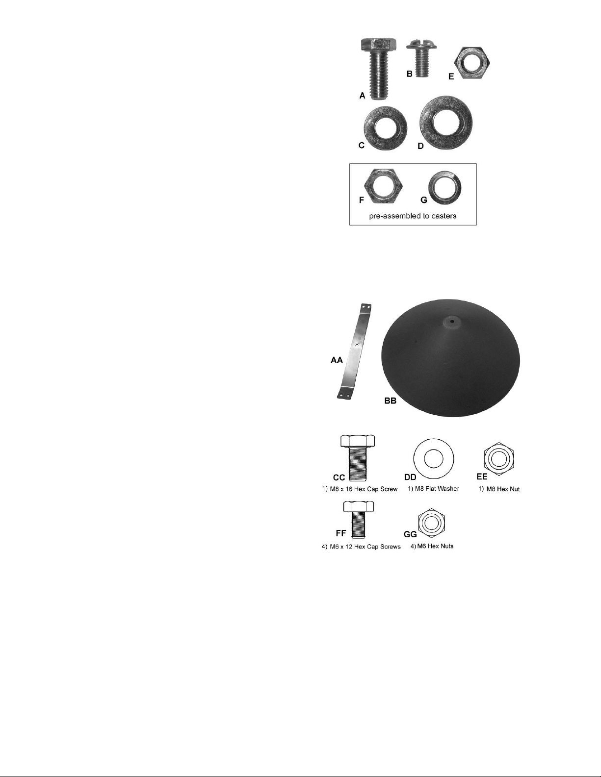
Main Hardware Ba g cont ent s ( Figure 1):
A – M8 x 20 Hex Cap Screws ( 24) *
B – M6 x 12 Pan Head Fla nge Screws ( 8) *
C – M8 Flat Washers (34) *
D – M10 Flat Washers (6) *
E – M8 Hex Nuts (16)*
F – 3/8" Hex Nuts (4) – on c asters
G – M10 Lock Washers (4) – on casters
Cone Assembly and Hard ware ( Figure 2):
AA – Support Bracket ( 1)
BB – Cone (1)
CC – M8 x 16 Hex Cap Screw ( 1)
DD – M8 Flat Washer (1)
EE – M8 Hex Nut (1)
FF – M 6 x 12 Hex Cap Screws ( 4)
GG – M6 Hex Nuts (4)
Figure 1: Main Hardware Bag contents
* A through E compri se PM1300-BMHP
Base Machine Hardwar e Package
Figure 2: Cone Assembl y and Har dware
CC through GG compr ise DC1100-HP2
Cone Assembly Hardware Package
Tools Require d f or Assembly
– 13mm Wrenches or Socket s
– 14mm Wrench
#2 Cross Point Screw Driver
6mm hex (“Allen”) wrench
7
Page 8

Base Machine Assembly
The dust collector must not be
connected to t he power source
during assembly. Failure to comply may result
in serious inj u ry!
All instructi ons on this page r efer to Figur e 3.
Base and Casters
1. The 3/8” hex nut (F) and M10 lock washer
(G) ar e pre-assembled to each caster (J) . For
shipping purposes, the lock washer has been
placed beneat h the hex nut. Remove hex nut
and lock washer from the caster shaft, reinstall the hex nut, then install the lock
washer above the hex nut, as shown.
2. I nstall the four casters (J) to t he underside of
the base (H) as follows:
3. Thread the caster shaft into the threaded hole
on the underside of the base (H), turn until
snug. Tighten the hex nut (F) against the
base with a 14mm wrench.
M otor and Fan Assembly
1. Place the base with casters down on the
ground.
2. Attach the motor and fan assembly (K) to the
base (H) using six M8x20 hex cap screws (A),
and six M10 flat washers (D). Hand tighten only
until all screws and washers are in place, then
adjust the motor a nd fan assembly ( K) until its
flanges are approximately f lus h with the edges
of the base (H). Tighten all screw s with a 13mm
wrench.
3. Attach the inlet guard (L) to fan housing (K)
using eight M6x12 pan head flange scr ews (B).
4. Press the inlet port (M) as far as it will go onto
the inlet guard (L).
To reduce the risk of injury f rom
moving parts, always keep both holes of inlet
port (M) covered with either the pr ovided cap or
dust hoses. Failure to comply may result in
ser io u s injur y !
Connector Tube and Switch Box
1. Place the lower gasket (N) on the fan housing
(K). Line up the rubber pegs on the gasket
(face down) with the holes in the housing.
2. Place the connector tube (O) on the fan
housing (K), making sure that the holes of the
mating flanges are aligned.
Note: Refer to Figure 3 to make sure that the
connector tube is facing the proper direct ion.
3. Insert an M8x20 hex cap screw (A), through the
M8 washer (C) and flanges of the connector
tube (O) and fan housing (K).
4. Place another washer (C) and a hex nut (E) on
the protrudi ng end of t he screw (A) and hand-
tighten only.
5. Mount the control box (P) to the two holes at
the front of the connector tube flange.
6. Repeat steps 3 a nd 4 for the rem aining screw
locations, hand tightening only.
7. Tighten all hex nuts wit h a 13mm wrench.
Collector Housing
Mount the collector housing (S) as follows:
1. Place an upper gasket (R) between the
collector housing (S) and connector tube (O).
Line up the pegs on the gasket (R) with the
holes in the housing (S).
2. Place the collector housing (S) on the
connector tube (O).
3. Insert a screw (A) through the washer (C),
connector tube flange (O), and collectorhousing f l ange (S).
4. Place another washer (C) and a hex nut (E) on
the protrudi ng end of t he screw (A) and hand-
tighten.
5. Repeat steps 1 through 4 for the seven
remaining screw locations.
6. Tighten all hex nuts wit h a 13mm wrench.
Support Bar
1. Align the bottom slots of the support bar (T)
with the holes in the base (H). Insert two
screws (A) and two flat washers (C) and hand
tighten only.
Note: If you are using the Canister Filter
System, proceed with steps 2 through 4
below. I f you are using the Filter Bag Syst em,
leave the support bar (T) as is, for further
assembly later, and proceed t o “ Handles”.
2. Align the top holes of the support bar (T) with
the holes at the rear of the collector housi ng
(S) and insert two screws (A) and two flat
washers (C).
3. Place a washer (C) and a hex nut (E) on the
protruding end of each screw (A) inside the
collector housi ng, and hand-t ig hten only.
4. Adjust the lower par t of the support bar (T) as
needed using its slots, until it is st r aight. Then
tighten all four screws on the support bar (T).
Page 9

Handles
1. Remove the plate (V) from the handle (U) by
loosening the two socket head cap screws
(W) with a 6mm hex wrench.
2. Install handle (U) to the holes in the collector
housing (S) by inserting the soc ket head cap
screws through the handle, the collector
housing, and into the plate on the opposite
side. Tighte n the screw s.
Note: Make sure the plate (V) is oriented
properly, as shown in the Detail in Figure 3:
The protrusions on the plate should face
away from the handle.
3. Install the seco nd handle to the housing.
Cone Installation
Install the cone assembly as shown in Figure 3a.
1. Mount the cone support bracket (AA) to the
housing with fo ur M6x12 hex cap screws (FF)
and tighten from beneath with four M6 hex
nuts (GG).
2. Install the cone (BB) fr om beneath using t he
M8x16 hex cap screw (CC), M8 flat washer
(DD) and M8 hex nut (EE).
Fi l t er S yst em
If your PM1300 Dust Collection system includes
filter bags, proceed to Filter Bag System Assembly
on page 10.
If your PM1300 Dust Collectio n system includes t he
canister kit, proceed to Canister System Assembly
on page 11.
Figure 3: Assembly and hardware identification
9
Page 10

Filter Bag System Assembl y
Note: If your dust collection system includes the
canister kit, proceed to Canister System
Assembly on page 11.
1. Insert a hanger bracket between support bar
and collector housing (Figure 4).
2. Align holes and secure with two M8x20 hex
cap screw s and two M8 flat washers outside
the housing, and two M8 flat washers and
two M8 hex nuts inside the housing. Hand
tighten only.
Figure 5
Figure 4
3. Make any needed adjustments to the
support bar, t hen tighten the two upper and
two low er screws on the support bar with a
13mm wrench.
4. Slide the hanger (Figure 4) onto the hanger
bracket as f ar down as it will g o. Rotat e the
hanger so that the hook at the top points
towar d the front of the machine.
5. Insert the ring (Figure 5) of the collector bag
into the bottom of the housing at an angle.
Pull down on the collector bag t o make sure
it “seat s” on the inner lip of t he housing.
6. Position the plastic window in front so that
you can easily see when collector bag is f ull.
7. Slide the top loop of the filter bag onto the
hanger hook ( Figure 6).
8. Thread the retainer strap (Figure 6) through
the loops on the filter bag, and fasten it to
the collector housing, as shown in Figure 7.
The retainer str ap should be tight enoug h to
provide a good seal.
Figure 6
Figure 7
Retainer strap
connection
10
Page 11

Canister System Assembly
(17mm wrench requi r ed)
9. Place the snap ring over the top of the
plastic collector bag, and fold over the bag
approximately t hree inc hes (Figure 8).
Figure 8
10. Insert t he snap ri ng of the collector bag into
the bottom of the housing at an angle
(Figure 9).
11. Pull down on the snap ring to make sure it
“seats” on the inner lip of the hous i ng.
Note: Make sure the snap ring “snaps” into
place in the housing, and also that the
plastic bag hangs down approximately 3
inches so that there are no air leaks.
12. Remove t he handle (Figure 10) from inside
the cani ster filter. M ount t he handle onto the
canister fil ter with two M10 hex nuts (A), two
M10 flat washers (B), and an M10 lock
washer (C). Arrange these fasteners
accordi ng to Figure 10. Tighten with a 17mm
wrench.
Figure 9
13. Place the canister on top of t he housing, and
push down to e nsure the canist er is seated
on the ho using.
14. Insert and tighten the four knobs into the
threaded holes on the canister ( Figure 10).
Note: The Powermatic® label on the front of t he
canister should have a negligib le effect upon air
flow. However, if zero effect is desired, t he label
can always be peeled off.
Figure 10
11
Page 12

Electr ical Connections
Electrical connections must
be made by a qualified electrician in
compliance with all relevant codes. This
machine must be prop erly grounded t o help
prevent electrical shock and possible fatal
injury.
The PM1300 is equipped with a single phase,
115/230 volt motor. It is factory wired for 115
volts. Keep in mind that a circuit bei ng used by
other machines (tools, lights, heaters, etc.) at
the same time will add to the electrical load.
Thus, it is recommended that the machine be
connected to a dedicated circuit, w ith a 30 amp
circuit breaker or f use for 115 volt operation; a nd
a 20 amp circuit breaker or fuse for 230 volt
operation. Local codes will take precedence
over recommendations.
The dust collector can be re-wired for 230V
operation as follows:
To convert to 230 volt operat ion:
1. Disconnect from power sour ce; unpl ug!
2. Connect the motor leads as shown in the
diagram inside the motor junction box; this
diagram is also shown on page 21 of this
manual.
3. O pen the control box cover by remo ving the
six screws, and move the voltage switch to
230V.
Check with a qualified electrician or service
personnel if the grounding instructions are not
completely understood, or if in doubt as to
whether the tool is properly gr ounded.
Repair or replace a damaged or worn cord
immediately.
Extension Cords
If an extension cord is needed, make sure t he
cord rating is suitable for the amperage listed on
the machine’s motor plate. An undersize cord
will c a use a dr op i n li ne vo ltage r esulting in loss
of power and overheating.
Use the chart in Figure 11 as a general guide in
choosing the correct size cord. If in doubt, use
the next heavier gauge. The smaller the gauge
number, the heavier the cord.
Rec o mm e nd ed G a uge s (A W G) of E xte n si on C ord s
Extension Cord Length *
25
50
75
100
150
200
Amps
< 5 16 16 16 14 12 12
5 to 8 16 16 14 12 10 NR
8 to 12 14 14 12 10 NR NR
12 to 15 12 12 10 10 NR NR
15 to 20 10 10 10 NR NR NR
21 to 30 10 NR NR NR NR NR
feet
feet
feet
feet
feet
feet
4. Replace t he plug on t he power cord w ith an
appropriate UL/CSA listed 230V p l ug.
5. When finished wiri ng, re-install juncti on box
and control box covers.
Ground i ng Inst r uct ions
This machine must be grounded. I n the event of
a malfunction or breakdow n, grounding provides
a path of least resistance for electric current to
reduce the risk of elect r ic shock.
Improper connection of the equipmentgrounding conductor can result in a risk of
electric shock. The conductor with insulation
having an outer surface that is green with or
without yellow stripes, is the equipmentgrounding conductor . If repair or replacement of
the electric cord or plug is necessary, do not
connect t he equipment-gr ounding conductor t o a
live terminal.
The hose or ductwork you use to connect the
tool to t he dust collector must also be grounded.
Make sure the voltage of your power supply
matches the specificat ions on the motor plate of
the dust collector.
*based on limit in g the line voltage drop to 5V at 150% of the
rated am per es.
NR: Not Recommended.
Figure 11
Overload Re-set
If t he Dust Coll ector overloa ds during operatio n,
press the re-set switch on the motor, shown in
Figure 12. Then re-start the machine.
Figure 12
12
Page 13

Operating the Machine
Connect the dust collector t o the power source.
If powe r is flo wing, a gr een in dicat or will lig ht o n
the face of the control panel.
To operate t he machine, use t he butto ns on the
control panel, or use the provided remote
control. To start the dust collector, pr ess the ON
button. If the remote control is used, aim it at the
control panel. The machine will remain running
until the OFF button is pressed. The digital
readout will always dis play 0 0 while running.
The remote control operates on two AAA
bat terie s . These will need replacing per iodica lly.
NOTE: The infrared sensor on the dust c ollector
has a 120° line-of-sight angle. See Figure 13.
Outside of this angle, the remote control may not
be effective.
Con nectin g the Dust Collect or to a
Machine
Use the proper type hose to connect the dust
collector to t he machi ne bei ng operated. Dryer
vent hose is not acceptable for this purpose.
Contact your nearest Powermatic distributor for
a full line of Dust Collector hoses and
accessories. You can customize your installatio n
and obtain maximum performance with dust
hoods, hoses, clamps, fitt ings, a nd blast gates.
Maintenance
Never perform maintenance
on this machine before turning it OFF and
removing p lug from power sour ce. Fa ilure to
comply may cause serious injur y!
Clean i ng the Filter Bag
Wearing a particle mask or
respirator for protection against fine dust
particles during cleaning is highly
recommended.
Figure 13
Setting the Timer
While the machine is running, press the TIME
button to activate the timer. Each time the button
is pressed and released, the run time is
incremented on the dig ital display by one minute
and can be set up to 99 minutes.
If t he TIME button is pressed and held, t he time
will scroll up to 99 minutes, then start again at
00. Release the button when the desired set
time is reached. The dust collector will run for
the amount of time displayed on the digital
display. If you scroll past 99 and release the
button at 10, for example, the machine will run
for ten minutes, not 110 minutes.
If the OFF button is pressed while machine is
running with the timer engaged, the machine
turns off and t he timer is dise ngaged; i.e., when
the machine is restarted, the timer must be
reset.
During first use a nd after cleaning, t he filter bag
may allow some d ust to esc ape. This is normal
and will stop aft er a short period of time.
Clean both the filter and collector bags
frequently to keep t he collector 's perf ormance at
its optimum. To clean:
1. Disconnect machi ne from the power s ource.
2. Unhook the filter bag from the hanger.
Shake the bag so that the majority of the
dust falls into the collector bag.
3. Loosen the retai ning str ap, and remove the
filter bag from the housing.
4. Turn the bag inside-out and clea n.
5. Turn the bag outside-i n and re-at tach to the
housing using the retainer str ap t o secure.
Removi n g the Collect or Bag
1. Disconnect machi ne from the power s ource.
2. Remove the collector bag by pushing the
ring of the collector bag upwards and pulling
the bag out at an angle.
3. Empty the contents into an appropriate
container.
4. Turn the bag inside-out and clea n.
5. Turn the bag outside-in and insert into the
housing.
13
Page 14

Clean i ng the Canist er Filter
Clean the canister filter frequently to keep the
collector's per formance at its opti mum. To clea n
the filter, turn the handle a couple of rotations so
the dust f alls into the clear plastic bag. Properly
discard the plastic collector bag when f ull.
Motor
Make fr equent inspections of the motor fan and
blow out (with low pressure air hose) or vacuum
any accumulatio n of for eign mater ial in order to
maintain nor mal motor ventilation.
Grounding Instructions
1. For all grounded, cord-connected tools:
This tool must be grounded. In the event of a malfunction or breakdown, grounding provides a path of least
resistance for electric current to reduce the risk of electric shock. This tool is equipped with an electric cord having an
equipment-grounding conductor and a grounding plug. The plug must be inserted into a matching outlet that is
properly installed and grounded in accordance with all local codes and ordinances.
WARNING: Improper connection of the equipment-grounding conductor can result in a risk of electric shock.
The conductor with insulation having an outer surface that is green with or without yellow stripes is the equipmentgrounding conductor. If repair or replacement of the electric cord or plug is necessary, do not connect the equipmentgrounding conductor to a live terminal. Do not modify the plug provided - if it will not fit the outlet, have the proper
outlet installed by a qualified electrician.
Check with a qualified electrician or service personnel if the grounding instructions are not completely
understood, or if in doubt as to whether the tool is properly grounded.
2. For grounded, cord-connected tools rated le ss than 15 am peres and intended for use on a nom inal
120V supply circuit:
This tool is intended for use on a nominal 120V circuit, and has a ground ed plug that looks like the plug
illustrated Sketch A in Figure 14. The tool has a grounding prong that looks like the plug illustrated in Sketch A in
Figure 14. A temporary adapter that looks like the adapter illustrated in Sketch B, may be used to connect this plug to
a 2 pole receptacle as shown in Sketch C if a properly grounded outlet is not available. The temporary adapter should
be used only until a properly grounded outlet (sketch A) can be installed by a qualified electrician. The green-colored
rigid ear, lug, and the like, extending from the adapter must be connected to a permanent ground such as a properly
grounded outlet box cover. Note: In Canada, the use of a temporary adapter is not permitted by the Canadian
Electrical Code.
Figure 14
3. For all other grounded, cord-connected tools:
This tool is rated more than 15 a mperes and is intended for use on a circuit having a no minal rating more
than 120 volts, and is factory-equipped with a specific electric cord and plug to permit connection a proper electric
circuit. Make sure that the tool is connected to an outlet having the same configuration as the plug. No adapter should
be used with this tool. If the tool must be reconnected for use on a different type of electric circuit, the reconnection
should be made by qualified service personnel.
14
Page 15

Replacement Parts
Replacement Parts are listed on the following pages. To order parts or reach our service department, call 1-800-2746848, Monday through Friday (see our website for business hours, www.powermatic.com). Having the Model Number
and Serial Number of your machine available when you call will allow us to serve you quickly and accurately.
Breakdown for PM1300 Dust Co llecto r ( Base Mach ine)
15
Page 16

Parts L ist for P M1300 Du st Collect or (Base Machine)
Index No. Par t No. Description Size Qty
1 .............. PM1300-101............Impeller Ho using................................................................................. 1
2 .............. PM1300-102............Housing Bracket ................................................................................. 1
3 .............. PM1300-103............Motor Bracket ..................................................................................... 1
5 .............. PM1300-105............Motor...................................................1-3/4HP, 115/230V, 1Ph .............. 1
................ PM1300-105MF .......Motor Fan (not shown) ........................................................................ 1
................ PM1300-105MFC ....Motor Fan Cover (not shown) .............................................................. 1
................ PM1300-105SC2 .....Starting Capacitor ( not shown)...........................300MFD, 125VAC ....... 1
................ PM1300-105RC2 .....Running Capacitor ( not show n) ..........................90µF, 250VAC............ 1
................ PM1300-105CS .......Centrifugal Switch (not shown) ............................................................ 1
................ PM1300-105RS .......Reset Switch (not shown) ..................................18A............................ 1
6 .............. PM1300-106............Motor Cord ......................................................................................... 1
7 .............. PM1300-107............Connector Tube .................................................................................. 1
8 .............. PM1300-108............Power Cord ......................................................14AWG x 3C .............. 1
9 .............. 420051....................Motor Ga sk e t...................................................................................... 1
10 ............ 430006....................Impeller ............................................................12” ............................. 1
11 ............ PM1300-111............Inlet Guard ......................................................................................... 1
12 ............ PM1300-112............Inlet Port ..........................................................2 @ 4”........................ 1
13 ............ 420203....................Inlet Cap ............................................................................................ 2
14 ............ 430034....................Rubber Gasket ................................................................................... 1
15 ............ PM1300-115............Base .................................................................................................. 1
16 ............ 402036....................Caster ................................................................................................ 4
17 ............ PM1300-117............Hou sing ............................................................................................. 1
18 ............ PM1900-122............Support Bar ........................................................................................ 1
19 ............ PM1300-119............Remote Control Switch Assembly ......................115/230V ................... 1
19-1 ......... DC RC-108 ..............S wi tc h Box ......................................................................................... 1
19-2 ......... DC RC-105 ..............D igi tal Swi tc h ...................................................................................... 1
19-3 ......... DC RC-106 ..............C ircuit Board ........................................................................... ........... 1
19-4 ......... DC RC-104 ..............S e a l ................................................................................................... 1
19-5 ......... DC RC-103 ..............S wi tc h Pl a te ............................................................................ ........... 1
19-6 ......... PM1900-108-6 .........Pan Head Screw...............................................M5x 8 ......................... 4
19-7 ......... DC RC-102 ..............S c re w ................................................................................................ 3
19-8 ......... ST039304 ...............Tapping Screw .................................................M3.5x12 ..................... 6
19-9 ......... DC RC-111 ..............T apping Screw .................................................M3.5x10 ..................... 1
................ PM1900-108-10 .......Display Label (not shown) ................................................................... 1
20 ............ PM1900-107............Mount Plate ........................................................................................ 1
21 ............ PM1900-129............Remote Control .................................................................................. 1
................ PM1900-129-1 .........Remote Control Label (not show n) ....................................................... 1
22 ............ ...............................Battery (local purchase) ....................................AA A ........................... 2
23 ............ 430035....................Rubber Gasket ................................................................................... 1
24 ............ 430036....................Rubber Gasket ................................................................................... 1
25 ............ PWBS14-254SN ......POWERMATIC Nameplate, Sm all ....................................................... 1
26 ............ 31A-208-2 ...............Strain Relief .....................................................PGA13.5 .................... 2
27 ............ PM1900-127............Han dle ............................................................................................... 2
28 ............ PM1900-128............Fastening Plate .................................................................................. 2
29 ............ TS-1490031 ............Hex Cap Screw ................................................M8x20...................... 24
30 ............ 6714154 ..................Hex Cap Screw ................................................1/4-20 x 3/8 ................ 2
31 ............ TS-2361061 ............Lock Washer ....................................................M6 ............................. 2
32 ............ KS050525 ...............Key ..................................................................5x5x25 ....................... 1
33 ............ TS-1550041 ............Flat Washer......................................................M6 ............................. 2
34 ............ TS-1540061 ............Hex Nu t............................................................M8 ........................... 20
35 ............ TS-0561031 ............Hex Nut............................................................3/8-16 ........................ 4
36 ............ TS-0561072 ............Hex Nut............................................................5/8-18UNF ................. 1
37 ............ TS-1490011 ............Hex Cap Screw ................................................M8x12...................... 11
39 ............ TS-1490041 ............Hex Cap Screw ................................................M8x25........................ 4
40 ............ SF069300 ...............Pan Head Flange Screw ...................................M6x12...................... 10
41 ............ TS-1550061 ............Flat Washer......................................................M8 ........................... 42
42 ............ TS-1550071 ............Flat Washer......................................................M10 ........................... 6
16
Page 17

43 ............ TS-155010 ..............Flat Washer......................................................M16 ........................... 1
44 ............ TS-2361018 ............Lock Washer ....................................................M8 ........................... 15
45 ............ TS-2361101 ............L ock Wash er ....................................................M10 ........................... 4
46 ............ TS-1504021 ............Socket Head Cap Screw ...................................M8x12........................ 4
50 ............ 998621....................Strain Relief ....................................................................................... 2
51 ............ PM1300-151............Inlet Guard ......................................................................................... 2
52 ............ 990855....................Pan Head Flange Screw ...................................3/16”x1/2”................... 1
53 ............ DC RC-111 ..............T apping Screw .................................................M3.5x10 ..................... 4
55 ............ PM1300-155............Cone.................................................................................................. 1
56 ............ DC1100-47-1 ...........Support Bracket .................................................................................. 1
57 ............ TS-1490021 ............Hex Cap Screw ................................................M8x16........................ 1
58 ............ TS-1550061 ............Flat Washer......................................................M8 ............................. 1
59 ............ TS-1540061 ............Hex Nut............................................................M8 ............................. 1
60 ............ TS-1482021 ............Hex Cap Screw ................................................M6x12........................ 4
61 ............ TS-231061 ..............Hex Nut............................................................M6 ............................. 4
................ PM2700-440............Wide Stripe (not shown) ............................................................... per ft.
................ PM2700-441............Narrow Stripe (not shown) ............................................................ per ft.
................ PM1300-BMHP........Base Machine Hardware Package (not show n) *................................... 1
................ DC 1100-HP2 ...........Hardware Package for Cone Assembly (index # 57 thru 61) ................. 1
* Base Machine Hardware Package i ncludes i ndex # 29, 34, 40, 41 and 42.
17
Page 18

Breakdown for PM1300 Canist er Filt er S yst em
18
Page 19

Parts L ist for P M1300 Can ister Fi lter System
Index No. Par t No. Description Size Qty
................ 1791086 ..................Canister Assembly (includes #1 thru 24) .............................................. 1
1 .............. PM1900-301............Fi l ter .................................................................................................. 1
2 .............. PM1900-302............Knob ................................................................M6x20........................ 4
3 .............. 331031....................Pad.................................................................................................... 1
4 .............. 331009....................Support .............................................................................................. 1
5 .............. ST049200 ...............Tapping Screw .................................................M4 x8 ......................... 4
6 .............. 331038....................Snap Ring .......................................................................................... 1
7 .............. 1791087 ..................Plastic Collection Bag (Package of 5) .................800x1050x0.1t mm ..... 1
8 .............. TS-1540071 ............Hex Nut............................................................M10 ........................... 2
9 .............. TS-1550071 ............Flat Washer......................................................M10 ........................... 2
10 ............ 331050....................Hand le ............................................................................................... 1
11 ............ 331051....................Soft Grip Ha ndle ................................................................................. 2
12 ............ TS-2361101 ............L ock Wash er ....................................................M10 ........................... 1
13 ............ BR000052 ...............Rivet ................................................................5-2 ............................. 3
14 ............ 331014....................Bracke t .............................................................................................. 1
15 ............ 150623....................Rubber Mount .................................................................................... 1
16 ............ TS-1540041 ............Hex Nut............................................................M6 ............................. 8
17 ............ 331052....................Shaft .................................................................................................. 1
18 ............ TS-1482041 ............Hex Cap Screw ................................................M6x20........................ 4
19 ............ TS-2361061 ............Lock Washer ....................................................M6 ............................. 4
20 ............ TS-1550041 ............Flat Washer......................................................M6 ............................. 4
21 ............ 331012....................Scraper .............................................................................................. 2
22 ............ 331017....................Plate .................................................................................................. 2
23 ............ 331015....................Plate .................................................................................................. 2
24 ............ TS-1482021 ............Hex Cap Screw ................................................M6x12........................ 4
................ PM1300-PLO...........Powermatic Label (not s hown) ...........................5-1/2x14 Oval ............. 1
................ PM1900-CHP ..........Canister Hardware Package (not shown) * ........................................... 1
*Canister Hardware Package includes index # 2, 8, 9 and 12.
19
Page 20

Parts L ist for P M1300 F ilter Bag S yst em
Index No. Par t No. Description Size Qty
................ 1791077B................PM1300 Collect io n and Filter Bag (i ncludes #1 t hru 5) .......................... 1
1 .............. 1791077F ................Filter Bag .........................................................30 micron ................... 1
2 .............. 410012....................Retainer Strap .................................................................................... 1
3 .............. 708699A .................Collection Bag .................................................................................... 1
4 .............. 402040....................Hanger............................................................................................... 1
5 .............. 523011....................Hanger Bracket .................................................................................. 1
20
Page 21

Elect ri cal Con nectio ns
21
Page 22

NOTES
22
Page 23

23
Page 24

WALTER MEIER (Manuf acturing) Inc.
427 New Sanford Road
LaVergne, Tennessee 37086
Phone: 800-274-6848
www.powermatic.com
www.waltermeier.com
24
 Loading...