

Page 1
OWNER’S MANUAL
AIR-COOLED DIESEL SILENT GENERATORS
MANUALE D’ISTRUZIONI
GENERATORE DIESEL SILENZIOSO RAFFREDDATO AD ARIA
MANUAL DEL USUARIO
GENERADORES DIESEL SILENCIOSOS REFRIGERADOS POR AIRE
MODE D’EMPLOI DE L’USAGER
GROUPES ELECTROGENES SILENCIEUX REFROIDIS A AIR
PMD5000s / PMD5050s
1
Page 2

PREFACE
PREFACE
Thank you for purchasing products from our company.
The manuals will help you to operate and maintain the machines rightly.
Please make sure to read the manuals carefully before the operating the
machines. Then the generators can work in the best condition and prolong
the life.
.Consumers should notice that this manual might differ slightly from
the actual product as more improvements are made to our products.
Some of the pictures in this manual may differ slightly from the actual
product as
well. The manufacturer reserves the right to make changes
at any time without notice and without incurring any obligation.
Please notice the following
warning.
If you will not operate the machines according to the manuals, there may
be body injury and dead.
So you MUST operate the machines after the fully understanding of the
manuals.
2
PR INDUSTRIAL s.r.l.
Loc. Il Piano
CAP 53031, Casole D’Elsa (SI)
ITALIA
Page 3

TABLE OF CONTENTS
TABLE OF CONTENTS
Chapter 1 Technical Specifications and Data………………….1
1-1 Technical specifications and data……………………………………1
1-2 Basic operating parameters…………………………………………..2
1-3 General dimensions and overview of the generators………………2
1-4 Parts name and control panel………………………………………….3
Chapter 2 Operating the Diesel Generator……………………….....4
2-1 Main points of safety during operation of the generator…………..4
2-2 Preparation before operation…………………………………………5
2-3 Checking the operation of the diesel engine………………………..8
2-4 Starting the generator set……………………………………………..8
2-5 Proper operation of the generator set………………………………..9
2-6 Loading…………………………………………………………………10
2-7 Stopping the generator………………………………………………11
Chapter 3 Maintenance……………………………………………………..12
3-1 Maintenance schedules……………………………………………...12
3-2 Storing for long periods of time……………………………………...13
Chapter 4 Troubleshooting……………………………………………….14
4-1 Troubleshooting procedures………………………………………...14
4-2 Questions and doubts…………………………………………….….14
Chapter 5 Circuit diagram………………………………………………….15
Appendix ⅠType of socket……………………………………………………..18
Appendix ⅡGeneral power list of appliance…………………………………20
3
Page 4
TECHNICAL SPECIFICATIONS AND DATA
1
CHAPTER 1 TECHNICAL
SPECIFICATIONS AND DATA
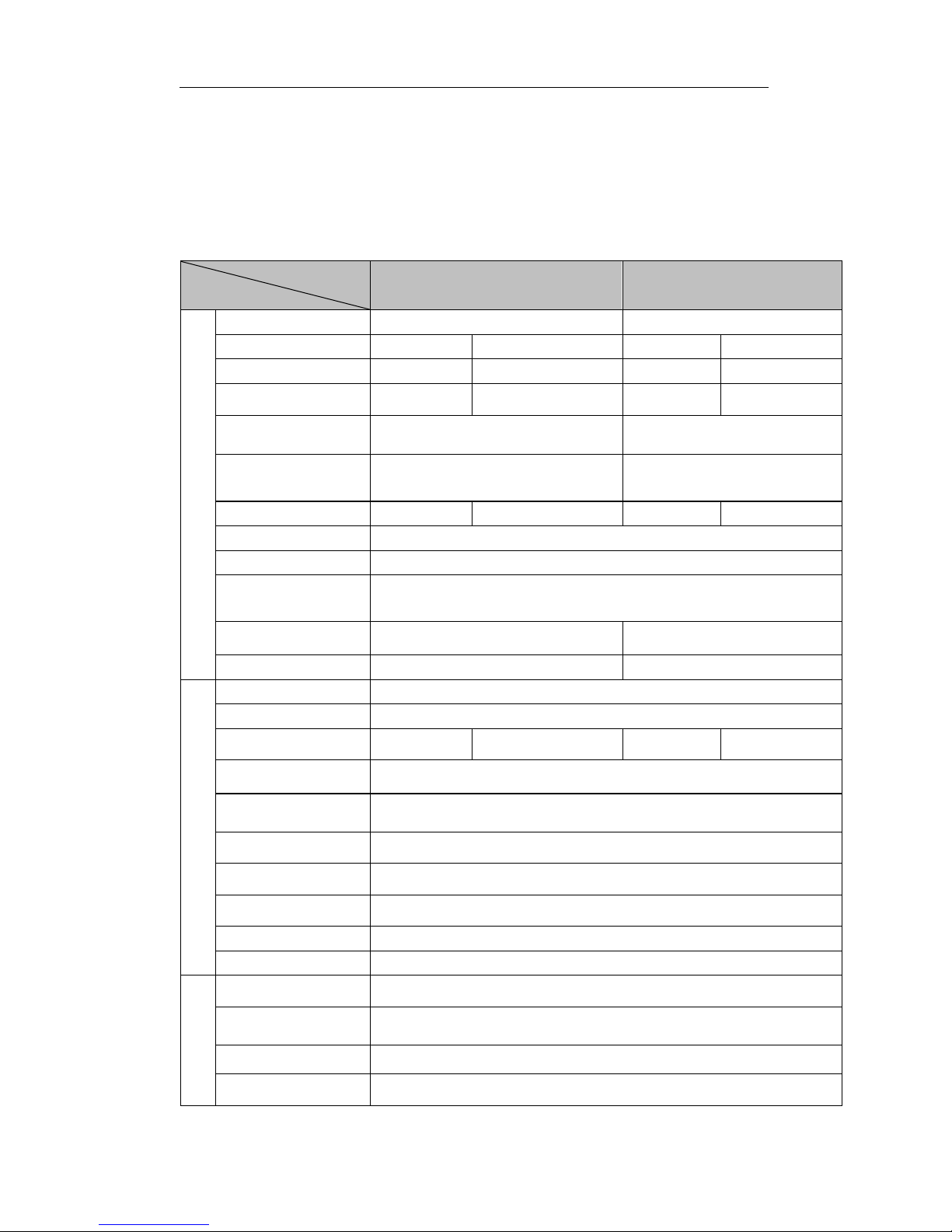
1-1 Technical specifications and data
Type
Item
PMD 5000s
PMD 5000s
Generator
Kind
Single phase
Three phase
Frequency(Hz)
50
60
50
60
Rated power (KVA)
4.2
4.5
4.2
4.5
Voltage (A.C)(V)
220V,230V,240V,110/220V,120/240V,
115/230V
400/230V,420/240V,380/220V,
127/200V
Excitation mode
Self-excitation brushless or
Self-excitation constant voltage(AVR)
Self-excitation constant
voltage(AVR)
Revolution (r/min)
3000
3600
3000
3600
Voltage (D.C)(V)
12
Current (D.C)(A)
7
Noise level dB(A)/7m
(0-100%load)
70-74
Power factor cosφ
1
0.8
Insulation grade F B
Diesel engine
Model of power
CF186F (E)
Kind
4-stroke single-cylinder air cooled direct injection
Max power (kW/rpm)
6.5
8.6
6.5
8.6
Bore × stroke (mm)
86×70
Cylinder displacement
(ml)
406
Cooling system
Force air-cooled
Lubricating system
Pressure splash, duplex type lubrication
Volume of lube oil (L)
1.65
Start system
Electric start
Fuel
Diesel fuel
Set
Fuel tank volume (L)
14.5
Low oil pressure
protection
Have
Total weight (kg)
186
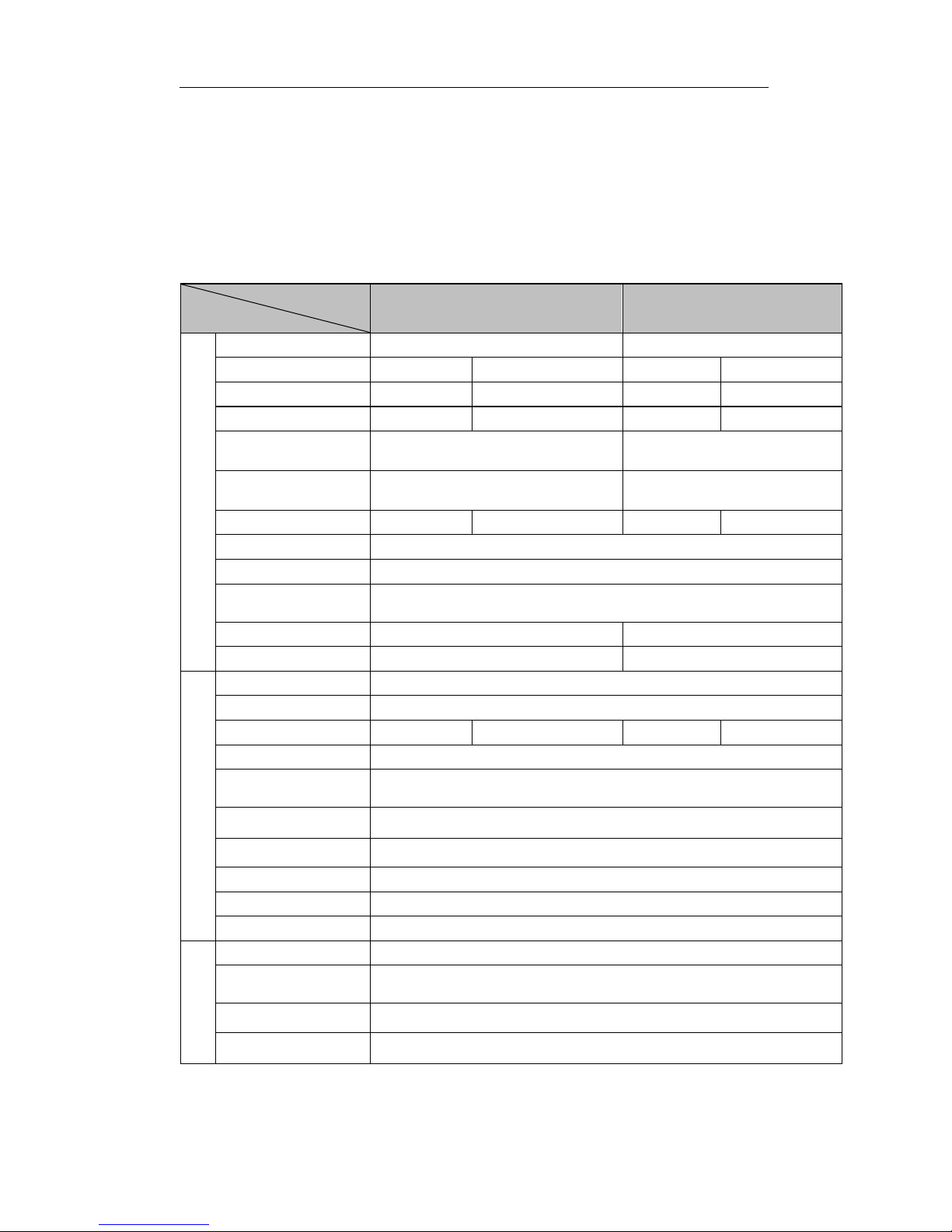
Overall dimensions
(mm)
920×520×700
Note: Get this power only after 30 hours’ initial run.
4
Page 5
TECHNICAL SPECIFICATIONS AND DATA
1-2 Basic operating parameters
1-2.1 Under the given conditions, the generator will output
the specified power in the table listed below.
Table 1
Height above sea level (ft)
Ambient temperature
RH
0
+60°F (+20°C)
60%
<3280.8 ft (<1000 m)
41~104°F (5-40°C)
90%
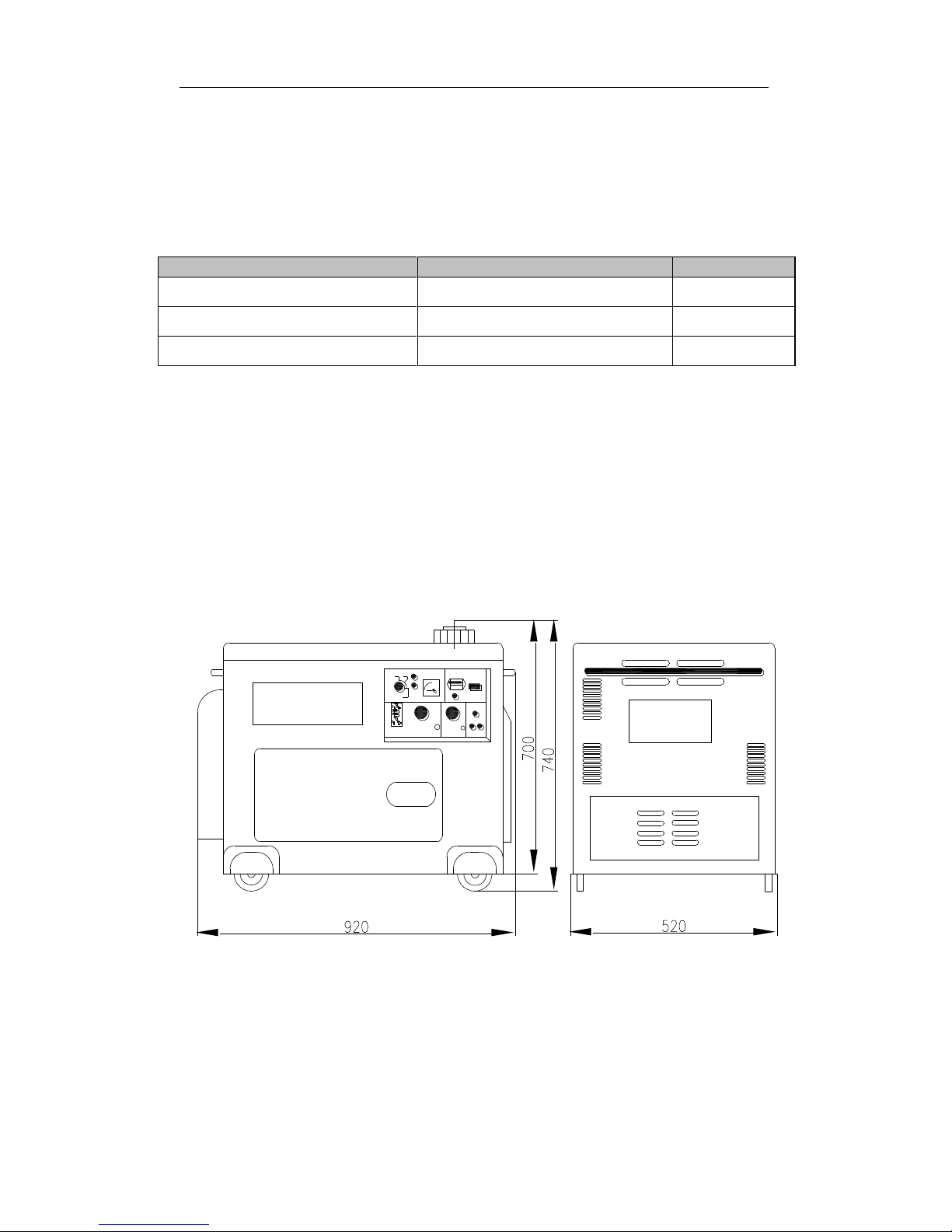
1-3 General dimensions and overview of the
generators
Please refer to the specification for the right dimension for
different models.
5
Page 6
TECHNICAL SPECIFICATIONS AND DATA
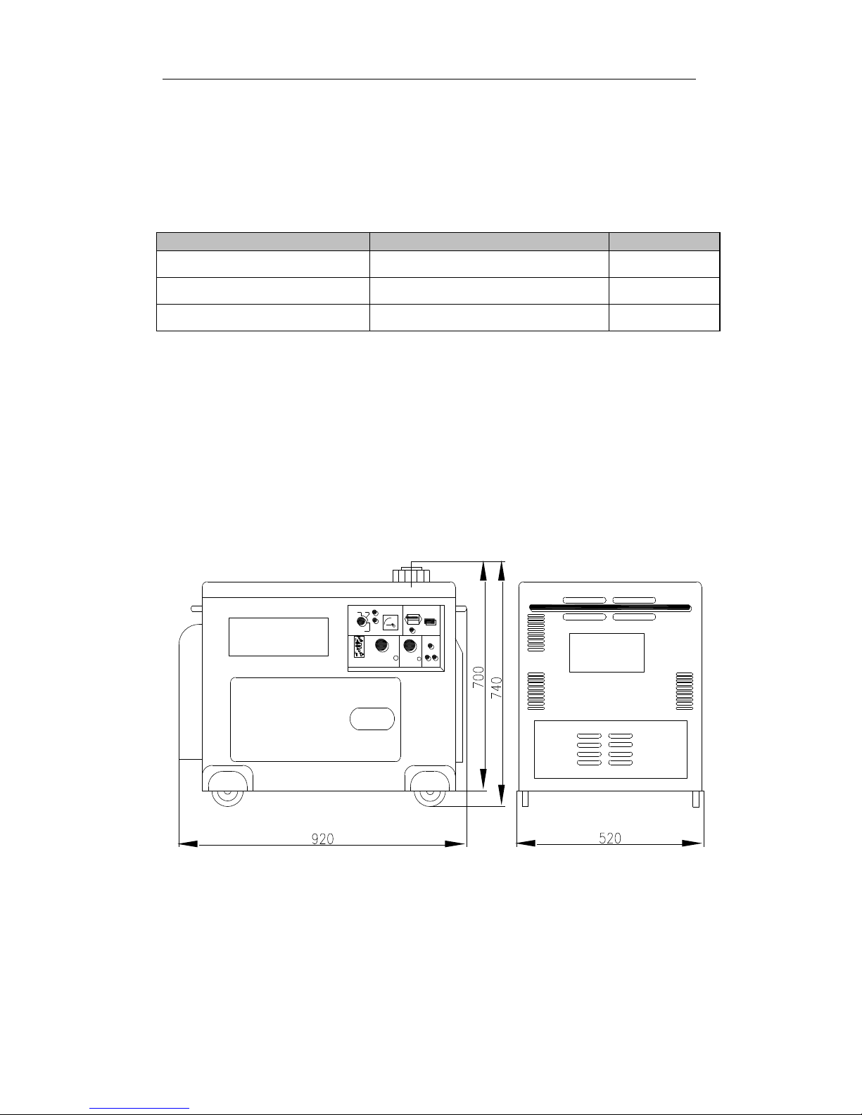
1-4 Parts name and control panel
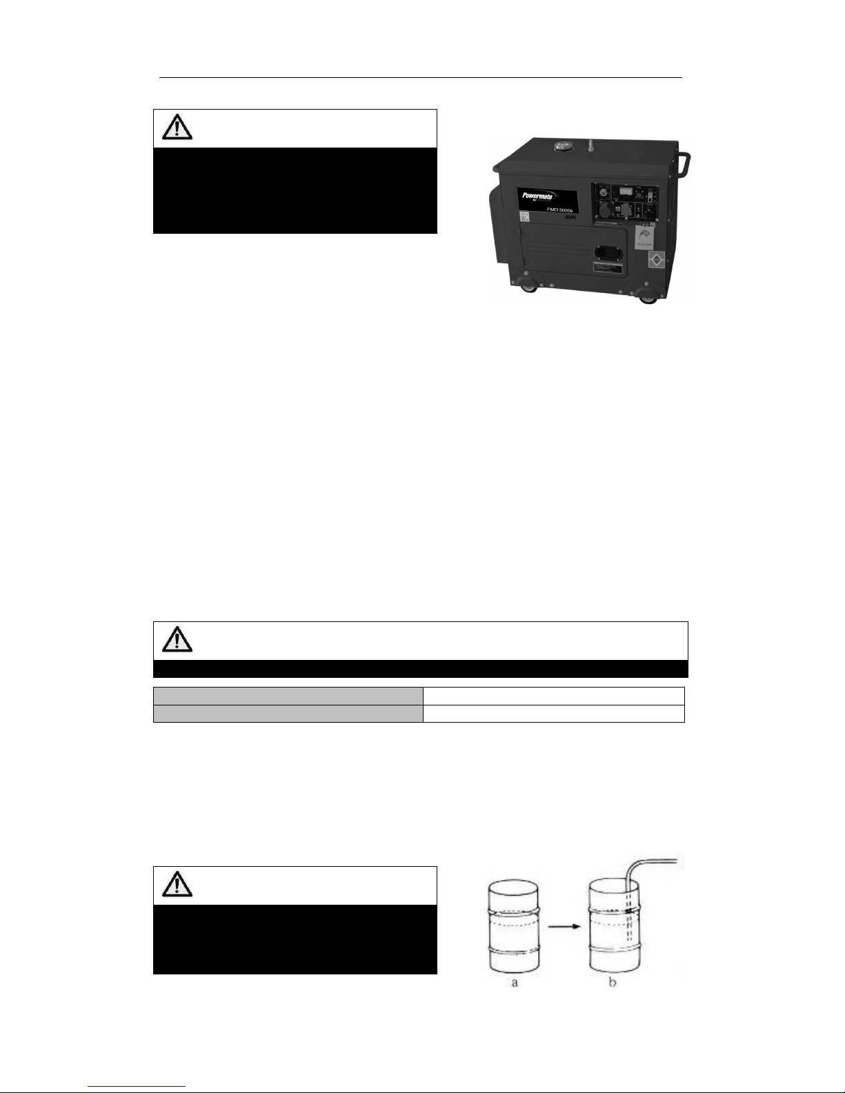
1-4.1 Parts Name
Cover of fuel tank
Label
Muffler
(inside)
Battery
(inside)
Door
Wheel
Engine
(inside)
Control Panel
6
Page 7

OPERATING THE DIESEL GENERATOR
1-4.2 control panel
Single phase Control Panel
Three Phase Control Panel
Low oil protection
indicating lamp (12V)
Voltmeter
99T1-300V
2P support for
breaker
Fuse10 A
Red wire
holder (107)
Black wire
holder (107)
Bolt to the
grounded
Socket SCHUKO
230V 16A
Socket 2P+T
CEE 230V 16A
Electric start switch
Connector
7 contacts
Low oil protection
indicating lamp (12V)
Voltmeter
99T1-300V
2P support for
breaker
Fuse10 A
Red wire
holder (107)
Black wire
holder (107)
Bolt to the
grounded
Socket 2P+T
400V 16A
Socket 2P+T
CEE 230V 16A
Electric start switch
Connector
7 contacts
7
Page 8

OPERATING THE DIESEL GENERATOR
CHAPTER 2 OPERATING THE DIESEL
GENERATOR
2-1 General main points of safety during
operation of the generator set.
In order to operate the generator set safely, please follow all the
instructions provided in this manual carefully. Doing so otherwise may lead to
accidents and or equipment damage.
2-1.1 Fire prevention
Do not use gasoline, kerosene or other fuels other than light diesel fuel.
Keep all flammable fuels away from the generator as the generator may
spark and ignite these gases.
Keep the diesel generator at least 1.5 meters away from buildings and or
other equipment.
Always operate your diesel generator on a level site.
2-1.2 Prevention from inhaling exhaust gases.
Never inhales exhaust gases emitted by the engine. The exhaust gases
contain toxic carbon monoxide.
Never operate your generator in places with poor ventilation. In order to
operate this machinery indoors, a suitable ventilation system for the building is
required to draw the poisonous exhaust gases out.
2-1.3 Prevention from accidental burns
Never touch the muffler and its cover when the diesel engine is running.
Never touch the muffler and cover after the diesel engine has been used,
as the muffler remains hot for a good period of time.
2-1.4 Electric shock and short circuits
Never touch the generator if the generator is wet. Also never touch the
generator if your hand is wet.
Never operate your generator if the weather conditions call for any type of
precipitation such as rain, snow, or fog.
To prevent electrical shocks, the generator should be grounded. Please
refer to Fig. 2-1 before beginning to use the electric generator.
Fig. 2-1
8
Page 9
OPERATING THE DIESEL GENERATOR
NOTE
When connecting devices to the
generator, make sure all other devices
are rated lower than the generators
output. Any generator socket should not
be overloaded over its regulated limit.
2-1.5 Other safety points
Before operating this generator, all operators
should have a good knowledge of how to break
the circuit if any accidents occur. Also, all operators should be familiar with all
the switches and functions of the generator before using this machine. While
operating the generator, wear safe shoes and suitable clothes during operation.
Always keep children and animals away from the generator.
2-1.6 Battery
Wear protective gear when working with the battery to protect your eyes, skin,
and clothing,. If you come in contact with the electrolytic liquid, wash it
immediately with clean water. Also, if the electrolytic liquid comes in contact
with your eyes, see a doctor immediately.
2-2 Preparation before operation
2-2.1 Fuel choices and fuel treatment
Use only light diesel fuel. Otherwise it will be difficult to start the generator.
The fuel should be filtered clean. Never let dust and water mix with fuel in
the fuel tank. Otherwise it will clog the fuel lines and oil nozzles. It may
also damage your pressure pump.
Note
It is dangerous to overfill the fuel tank. Never exceed the red piston in the filter.
Type
PMD 5000s
The effective volume of fuel tank:
14.5L
a. After purchasing fuel, put it into a drum and let it sit for 3-4 days.
Otherwise it contains granule, which will result to clog the fuel lines.
b. 3-4 days later, insert half of the fuel sucker into the drum, (water and
impurities stay in the lower portion of the drum) .Otherwise they will be taken in.
Contaminated fuel will cause accelerated wear to fuel system part.
NOTE
Never smoke near the opening of the
fuel tank. Do not let sparks get near the
fuel or fuel tank and do not overfill tank.
After filling, tighten the fuel cap.
9
Page 10
OPERATING THE DIESEL GENERATOR
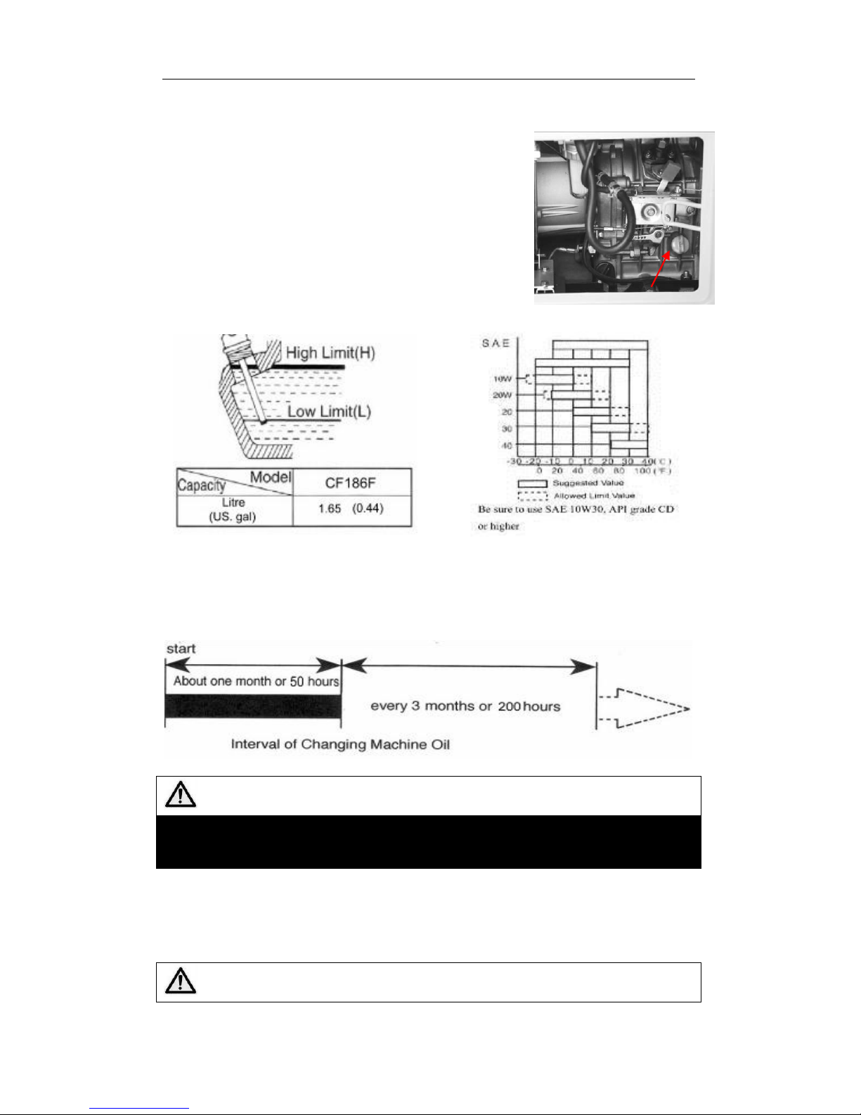
2-2.2 Check and fill engine oil
Make sure the generator is on level ground and
remove the dipstick from the engines. if not, the
oil level of the engine which show us are wrong.
Check if the oil level is between the high limit
and low limit. If the engine is new or oil is not
enough, fill the engine with the right engine
oil(10W30).
Put the dipstick back into the hole to check the
engine oil level.
Choose the right engine oil
Engine oil is the most important factor in determining the life of your generator
engine. If you use poor engine oil or if you don’t change the oil regularly, the
piston and cylinder will wear easily or seize up. Also, the life of the other parts
in your engine such as bearings, and other rotating parts will shorten
considerably.
NOTE
Although there is an alarm system to check for low oil pressure, it is always a
good idea to check the amount of oil inside the engine. If the oil level is low, fill
it before starting the engine.
A good time to drain the oil from the engine is when the diesel engine is still hot.
If the engine is fully cooled, it is more difficult to drain all the oil out or some
impurities will remain in the engine.
WARNING
Oil dipstick
10
Page 11
OPERATING THE DIESEL GENERATOR
DO NOT fill engine oil when the machines are running.
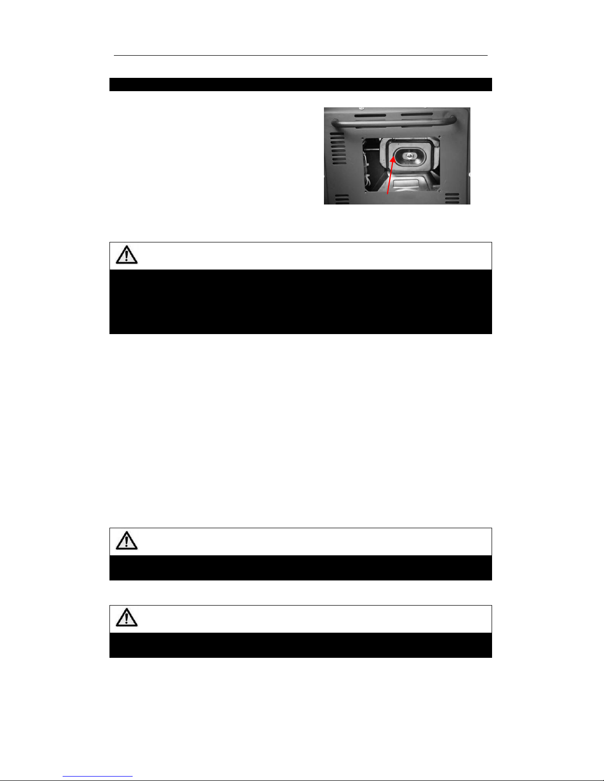
2-2.3 Checking the air filter
(1) Open the cover of generators, you will
see the air filter assembly.
(2) Loosen the butterfly nut of air filter,
take the cover of the air filter off and take
the air filter element out.
NOTE
Do not use detergent to wash the air filter element.
When the performance of the engine decreases or when the color of the
exhaust gases is bad, exchange the filter element.
Never start the engine without the air filter as foreign objects may enter the
intake and damage the engine.
(3) After replacing the air filter element, replace the cover and tighten the
butterfly nut firmly.
If not replace the air filter immediately, the dust in the air will not be adsorbed.
In that case, it stands a good chance to block the air way.
2-2.4 Check the oil way
The fuel and oil in a new engine is drained before sold. Before you start the
engine, please fill the fuel tank and engine oil first. Then, check to see if there
are air bubbles in the engine. If there are, follow these procedures. Loosen the
connecting nut between the oil injection pump and oil pipe. Bleed the air from
the system until there are no more bubbles. Then replace the connecting nut
and tighten it.
2-2.5 Check the generators
(1) Close the power switch and disconnect from any load. Otherwise it may
cause electric shock. Even make injures or death.
WARNING
Make sure to close the power switch.
Make sure to ground the generators.
(2) How to use double voltage generators
Push the voltage switch to the right voltage you will use.
WARNING
Make sure to disconnect any load before starting the generators. It is very
dangerous if not.
Air filter cover
11
Page 12
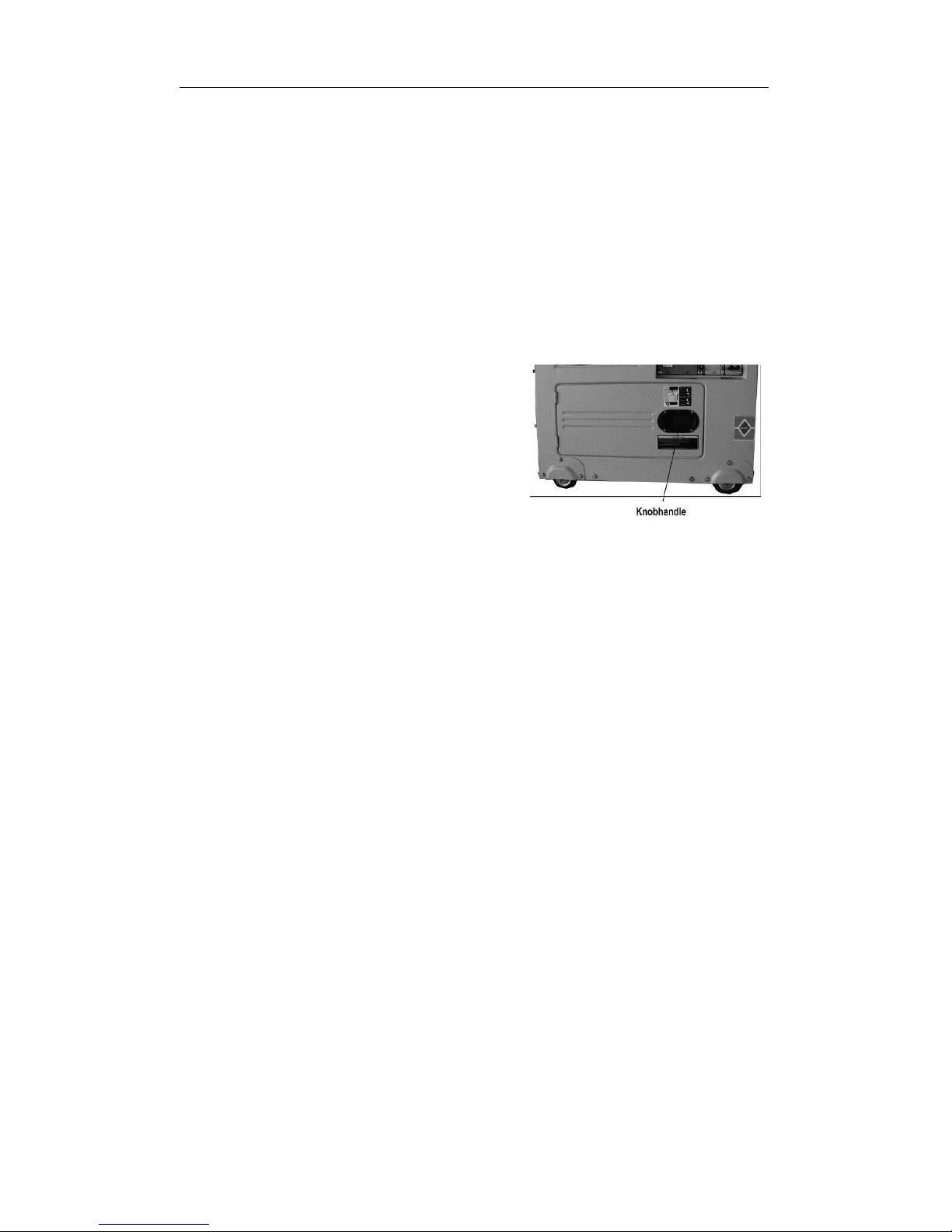
OPERATING THE DIESEL GENERATOR
Knob handle
2-3 Checking the operation of the diesel engine
2-3.1 Low-pressure alarm system.
Diesel engines have a low-pressure sensor system where if the oil pressure
drops too low, the sensor will shut the engine off. The purpose of having this
system is to ensure that the engine does not seize up. If there is not enough oil
in the engine, the temperature of the oil will be raised too high. On the contrary,
if there is too much oil in the engine, the engine oil can slow the engine down
considerably.
2-3.2 How to open the case door/cover
(1) Open the case door: Pull the handle outward and open the door. Do these
checks daily.
(2) Loosen the outer cover bolt of the air filter
and outer cover of the oil nozzle, and then
check the air filter.
(3) Check the outer cover of the oil nozzle.
Loosen the butterfly nut and open the outer
cover.
2-3.3 Engine break in
When you purchase a brand new engine, the engine must be properly broken
in. The break in period is about 20 hours.
(1) Avoid overloading the engine when brand new
(2) Change the engine oil according to specifications. An oil change for a brand
new engine is about 20 hours or every month, an older engine, the oil change
is about 100 hours or three months.
If not breaking in, it will reduce the serving life, reliability and cost performance
of the engine. At last, the life of the generator also be shortened.
2-4 Starting the generator set
2-4.1 Starting.
(1) Make certain the generator is on a " FLAT " or " LEVEL SURFACE ". If the
engine is tilled, fuel spillage may result.
(2) Disconnect all electrical loads from the generator. Never start and stop the
generator with electrical devices plugged in or turned on. Otherwise it will result
to short circuit, even break down the starter motor.
(3) Turn the Fuel Valve to the " ON " position. Otherwise fuel will be not enough
to start the generator.
(4). Push the speed level to " run " Position. If do not so, the start of generator
will be fail.
(5) Insert the ignition key to the “ off ” position.
(6) Electric Start: Turn the ignition key to the " Start " position and hold until
12
Page 13
OPERATING THE DIESEL GENERATOR
engine starts. Otherwise it will be abnormal to electrify. ( If the engine fails to
start within five seconds, release the key and wait at least ten seconds before
attempting to start the engine again. If holding on starting, it will heat up motor.)
(7) As engine warms up, move the ignition key to " on " position. Otherwise the
fuel way will cause serious trouble.
2-4.2 Battery
NOTE
If you crank the starter too long, the battery may be drained too much to
provide enough energy for proper engine ignition.
Also, when the diesel engine is operating, let the key retain in the “ON”
position.
IMPORTANT NOTE
All of our units come with a maintenance free battery. You do not need to add
any battery acid.
2-5 Proper operation of the generator set
2-5.1 Operating the diesel engine
1. Pre-heat the diesel engine for 3 minutes under no load conditions.
2. First check the low oil pressure indication light in the panel. If the light is red,
please fill into enough oil.
3. Do not adjust the speed limit regulation bolt or the fuel adjustment bolt.
These bolts have been set by the factory already, changing them will affect the
properties of the engine performance.
2-5.2 Checks during engine operation
1. Check to see if there are abnormal noises. Check the joint of oil passages,
fuel passages, water passages and air passages frequently to find out whether
there is any leakage. If any, remove at once. Otherwise serious troubles may
be caused.
2. Check to see if the performance is good or bad.
3. Check the color of the exhaust gases (whether it is too black or too white).
If any of these conditions exist, stop the engine and find the cause of the
problem. If no problems are found, please contact your local dealer or our
nearest company branch.
13
Page 14
OPERATING THE DIESEL GENERATOR
2-6 Loading
2-6.1 Connecting Electrical Loads:
1. Let the engine stably and warm up for a few minutes after starting.
2. Plug in and turn on the desired VOLTAGE AC Output with electrical loads.
IMPORTANT NOTE
DO NOT connect 3-phase loads to SINGLE PHASE Diesel Generator.
DO NOT overload this generator.
To prolong the life of your generator and properly connect your appliances,
please follow these steps to add electrical load:
3. Start the generator with NO ELECTRICAL LOAD ATTACHED.
4. Allow the engine to run for several minutes to STABILIZE.
5. Plug in and turn on the first item. It is best to attached the item with the
LARGEST LOAD first.
6. Allow the engine to stabilize.
7. Plug in and turn on the next item.
8. Allow the engine to STABILIZE.
9. Repeat step 4-5 for each capacity when adding loads.
2-6.2 Output of electricity
1. Raise the revolutions per minute (turn the speed handle to the max setting)
of the generator to get the maximum power out of the generator. If not, the
automatic voltage regulator device will excite and doing this for long periods
of time will cause the AVR to burn. For the rated speed of the generator,
please refer to Chapter 1, item 1-1 technical specification and data.
2. Observe the pointer of the voltmeter, it should point to the voltage you need
5%. Meanwhile put the switch in the GEN (generator) position. The AC
voltage from the socket of the power supply can be output.
2-6.3 Charging the battery
1. For the electric starter on the generator sets, the 12V battery is automatically
charged through the regulator on the side of the engine when it is running.
2. If the generator is not used for long periods of time, the battery should be
disconnected to avoid energy loss from the battery.
3. Do not connect the negative and positive terminals of the battery together at
any time. Doing so will damage the battery and cause serious injuries.
4. Do not reverse the polarities when attaching the battery cables to the battery.
NOTE
Do not start more than two devices simultaneously. Each device should be
started one by one to prevent overloading the generator.
The generator should be running at 3600 revolutions per minute in order to
achieve the (60 Hz) frequency. The speed of the engine can be adjusted from
the speed governor.
14
Page 15
OPERATING THE DIESEL GENERATOR
Doing so will damage both the battery and the electric starter.
5. When charging the battery, the battery produces flammable gases. Do not
smoke, let flames, and sparks get near the battery while it is charging as this
may cause a fire.
To avoid sparking while connecting the cables to the battery, first, connect the
cables to the battery then to the motor. To disconnect battery cables, first
disconnect the motor end of the cable.
2-7 Stopping the generator
1. Take the electrical load off the generator, when you want to stop the
generators.
2. Move the air switch to “off” position. If not, the short circuit will appear.
3. Put the speed handle in the “RUN” position and let the engine run for 3
minutes after unloading. Do not stop the diesel engine immediately let it warm
down. Stopping the diesel engine suddenly may raise the temperature of the
engine abnormally and lock the nozzle and damage the diesel engine.
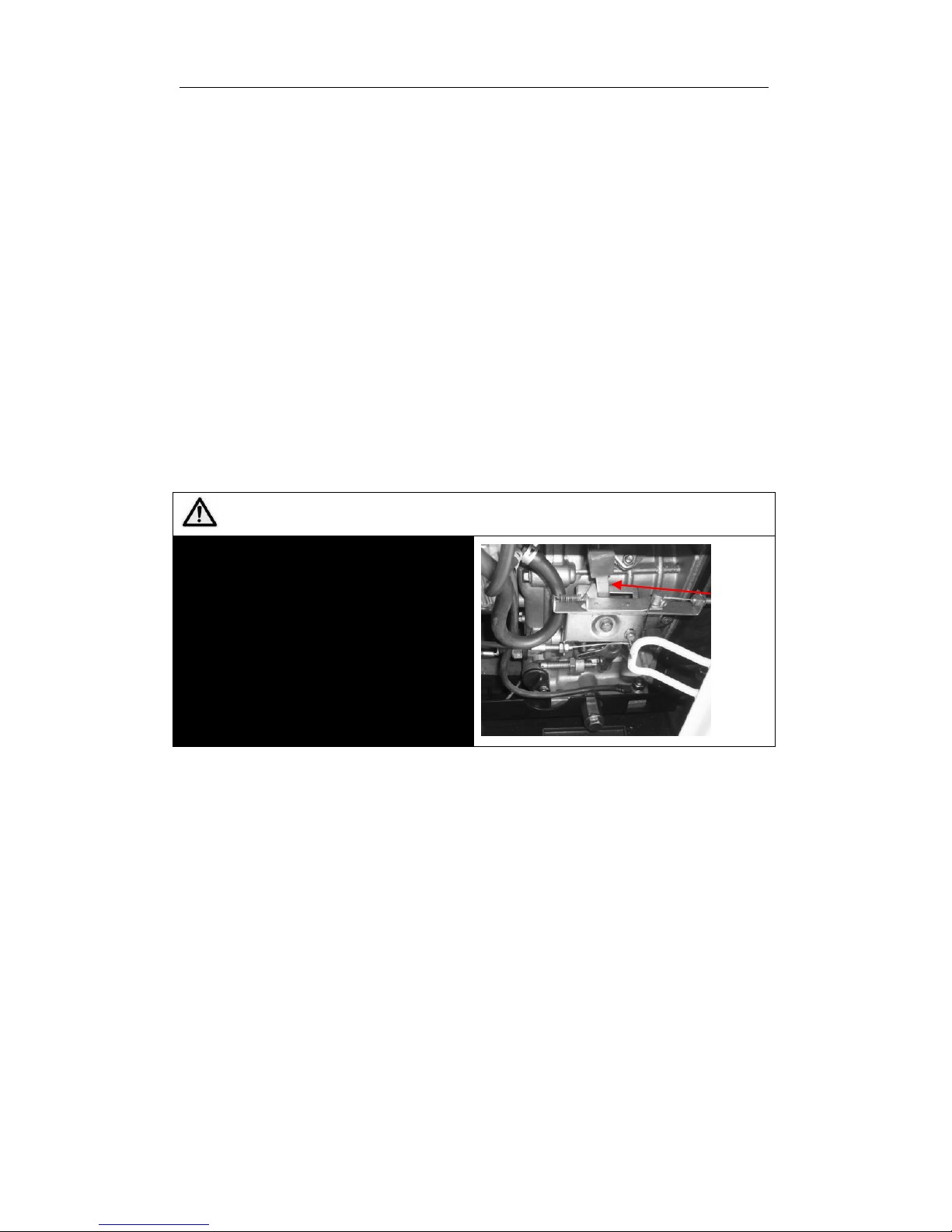
NOTE
1. If you cannot stop the engine with a
load on it, then remove the load first
than stop the engine.
2. Press down on the brake handle.
3. If equipped with an electric starter,
turn the key to the “Off” position.
4. Put the fuel handle to the “S”
position.
4. Put the ignition key to “off” position. Then the generators will stop.
5. Move the speed level to “stop” position, which make sure to cut off the fuel
way.
6. Close the fuel valve. But don’t stall the generator by turning off the cock of
the fuel tank in case air enters fuel passages to cause difficult starting next
time.
Speed
handle
15
Page 16

MAINTENANCE
CHAPTER 3 MAINTENANCE
3-1 Maintenance schedules
Keeping your generator well maintained will prolong the life of your generator.
Everything needs to be checked including the diesel engine, generator, control
cabinet, and frame. For overhauling procedures, please refer to the instruction
manual of the relative subassembly. If you need these manuals, please call our
company and we will send you one.
Before starting the maintenance, make sure the diesel engine is off.
Please refer to the Table 3-1 for the proper maintenance schedule.
Table 3-1. Maintenance schedule for diesel generator set
Time
Item
Everyday
After 1
month or
50hours
Every 3 month
or 200 hours
Every 6 month
or 400 hours
Every 1year
or 1000 hours
Check the fuel
level and refill
○Before
starting
Drain the fuel tank
○
Check and fill
enough engine oil
○
Clean the fuel
filter
○
Check fuel oil
leakage
○after
every
operating
Check and screw
each fastened part
○
●screw the bolt of
cylinder head firmly
Check injector
●
Check injection pump
●
Check fuel pipe
●If necessary
exchange it
Check the lube. oil level in
the oil pan and refill
○before
starting
Replace the lube.
oil
○the first
time
○the second time
and afterward
Clean lube. Oil
filter
○the first
time
○the second time
and afterward
Check the air
cleaner element
○the first
time
○the second time
and afterward
Change the core
of air filter
If damaged or smeary , change it in time
Check the battery
liquid level and
refill
○
Adjusting the intake
and exhaust valve
clearance
●the first
time
●the second
time and
afterward
Grind air intake and
air exhausted gate
●
Exchange piston ring
●
Check electric brush
and slide ring
●
Check insulation
resistance
The time of stop is over 10 days ○
Note: the quality period of the injector and injection pump is 1500 hours
or two years. There into,● means it should operate with special
tools, or can be checked by dealer.
16
Page 17
MAINTENANCE
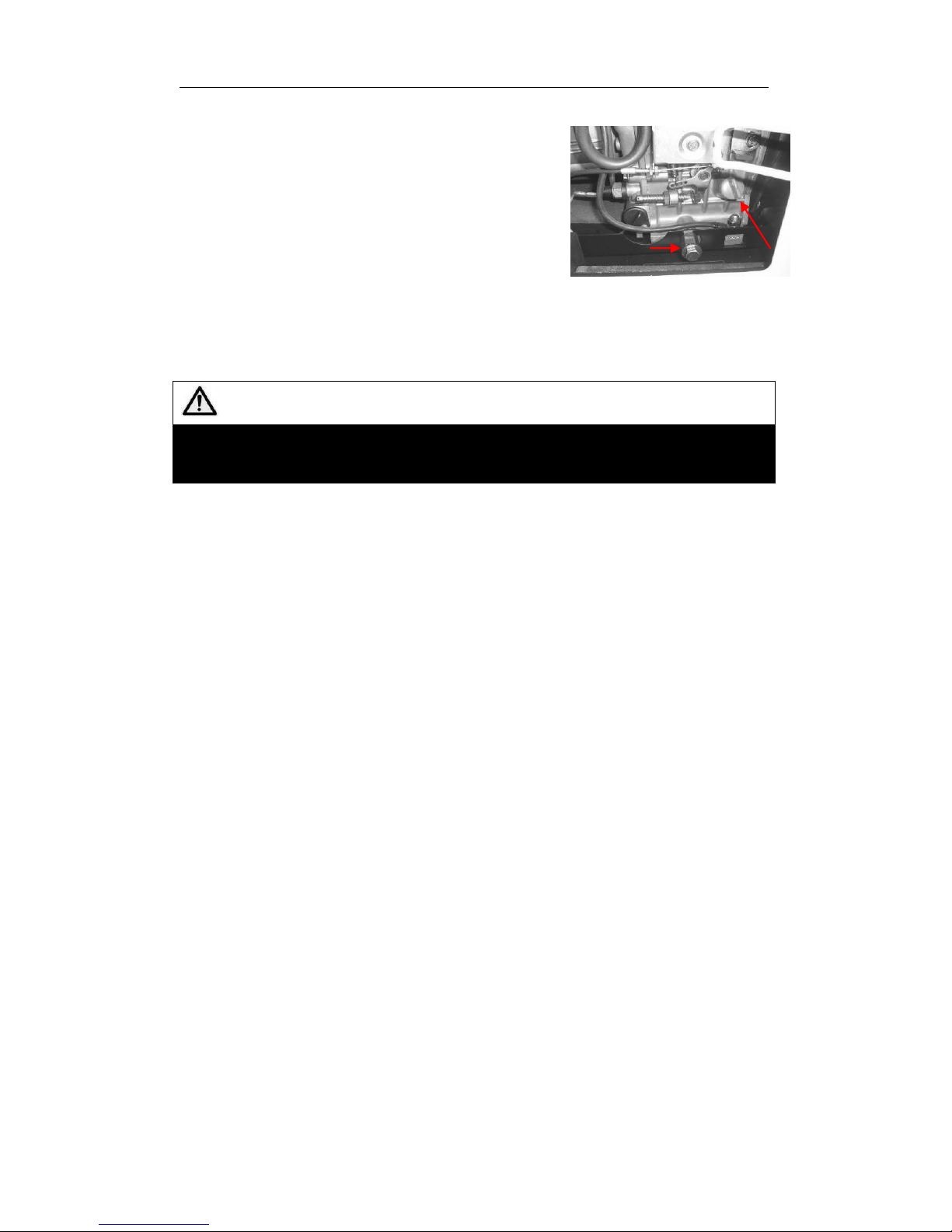
Dipstick
Oil drain bolt
3-1.1 Changing the engine oil (every 100 hours)
Take the oil cover off. Remove the oil drain plug
when the diesel engine is still hot. Be careful of
hot oil and hot engine as you may get burned. The
bolt is located at the bottom of the cylinder. After
draining the oil, put the bolt back and tighten it.
Then fill with the proper engine oil to the proper
level.
3-1.2 Air filter maintenance schedule
1. Clean air-filter every 6 months or 500 hours of operation.
2. If necessary, exchange it.
3. Do not use detergent to clean air filter element.
NOTE
Never start the engine without the air filter. This can cause serious damage to
the engine if foreign objects enter the intake system. Always change the air
filter on time.
3-1.3 Fuel filter maintenance
1. The fuel filter should be cleaned often to keep the engine running at
maximum performance.
2. The recommended time period for cleaning the fuel filter is 6 months or 500
hours of operation.
a. To do this, first drain the fuel from the fuel tank.
b. Loosen the small screws on the fuel switch and remove the fuel filter form
the port. Use diesel fuel to clean the fuel filter. Also, remove the fuel injector
and clean the carbon deposit around it. The recommended time period for this
is 3 months or 100 hours.
3-1.4 Cylinder head bolt tensions
The cylinder head bolts should be tightened to specifications please refer to the
diesel engine manual for specifications and the special tools required to do this.
3-1.5 Battery check
Make sure the battery acid is full. The engine uses a 12V battery. Due to
numerous starting cycles, the battery acid may be used up. Also, before filling,
verify that the battery is not damaged in any way. Add distilled water to the
battery when filling. Perform checks on the battery once a month.
3-2 Storing for long periods of time
If your generator needs to be stored for long periods of time, the following
preparations should be made.
1. Start the diesel engine for 3 minutes then stop it.
2. When the engine is still hot, change the engine oil with new engine oil of the
proper grade.
3. For electric started generator, press the decompression handle down and
crank the engine for 2-3 seconds. To do this, put the starter switch in the “Start”
position. (Do not start the diesel engine)
4. Clean the engine and store it in a dry place.
17
Page 18

TROUBLESHOOTING
CHAPTER 4 TROUBLESHOOTING
4-1 Troubleshooting procedures
Causes of malfunction
Remedy
Diesel cannot be started.
Not enough fuel
Add enough fuel
The switch of fuel is not at
“OPEN” position.
Turn the switch of fuel to “OPEN”
position.
High-pressure pump and nozzle
do not inject fuel or the injected
amount is less.
Disassemble the nozzle and adjust it
at test table.
Speed control lever is not at
“RUN” position.
Turn speed control lever to “RUN”
position.
Check level of lubrication oil.
The standard oil amount of
lubricating oil should be between
high graduation “H” and low
graduation “L”.
It is not quick and powerful to pull
reactive starter.
Start diesel engine in accordance
with the requirements of “start
operation procedures”.
Nozzle exist dirt.
Clean the nozzle.
Accumulator has not electricity.
Charge the accumulator or
exchange it.
Generator cannot generate electricity
and has not welding voltage
Master switch (NFB) is not be
switched on.
Turn master switch handle to “ON”
position.
Carbon brush of generator was
worn. The contact is bad.
Exchange the carbon brush.
The contact of socket is bad.
Adjust the contact feet of socket.
The rated revolution of engine
cannot be reached.
Make it reach to the rated revolution
in accordance with the
requirements.
AVR automatic governor is
damaged.
Exchange it.
The potentiometer of current
regulation for electric welding is
damaged.
Exchange it.
If you are still having trouble, please contact with your nearest dealer or with
our company directly if necessary.
4-2 Questions and doubts
1. Model of diesel engine generator and engine model number.
2. State of residency.
3. Number of hours of operating equipment along with the problem that occurred.
4. A detailed condition and time when the problem occurred, in other words,
climate and atmosphere.
18
Page 19
CIRCUIT DIAGRAM
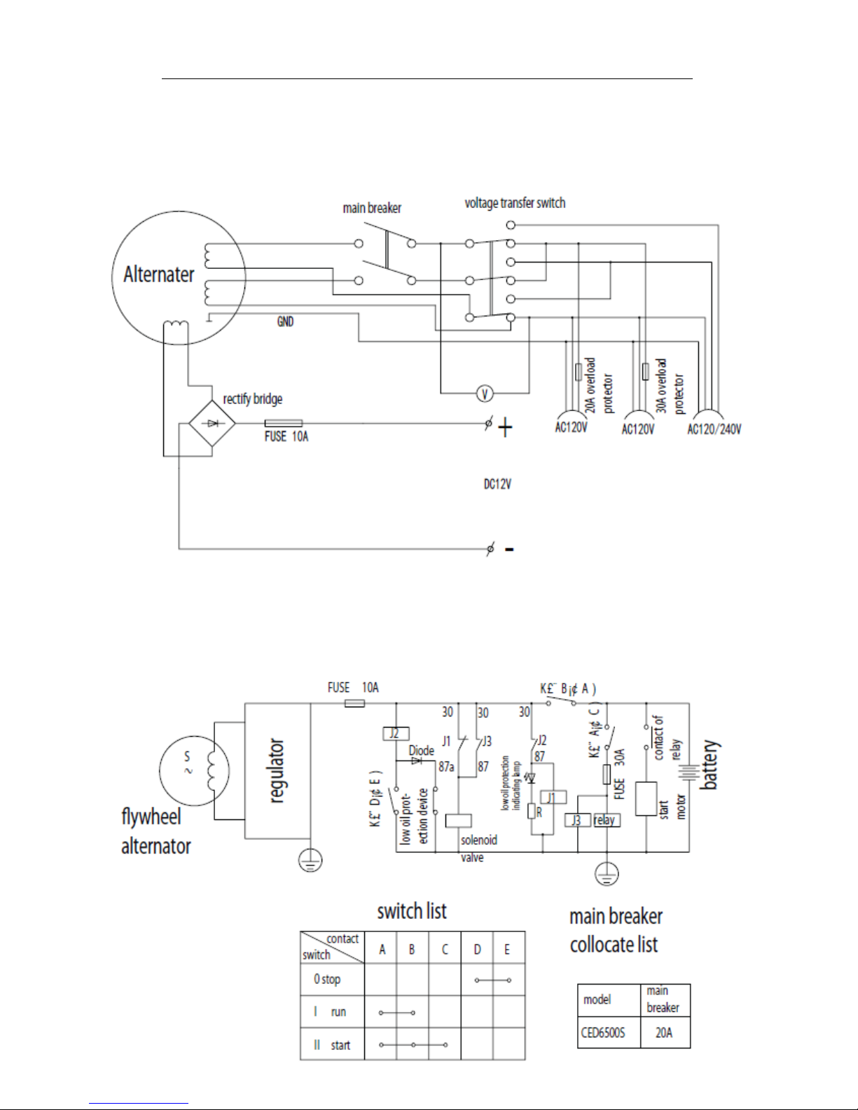
CHAPTER 5 CIRCUIT DIAGRAM
Figure 5-1 single-phase double voltage circuit diagram
19
Page 20
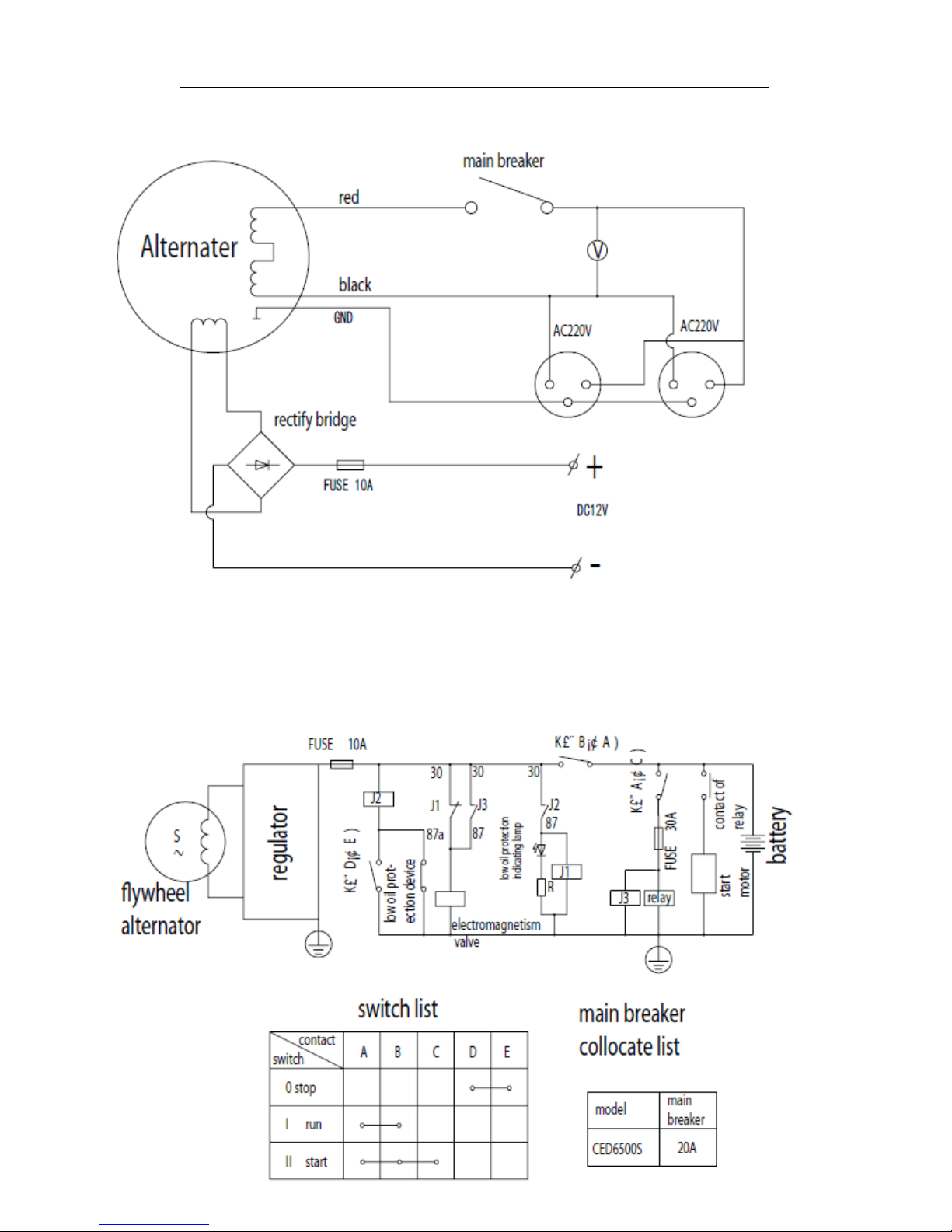
CIRCUIT DIAGRAM
Figure 5-2 single-phase single voltage circuit diagram
20
Page 21
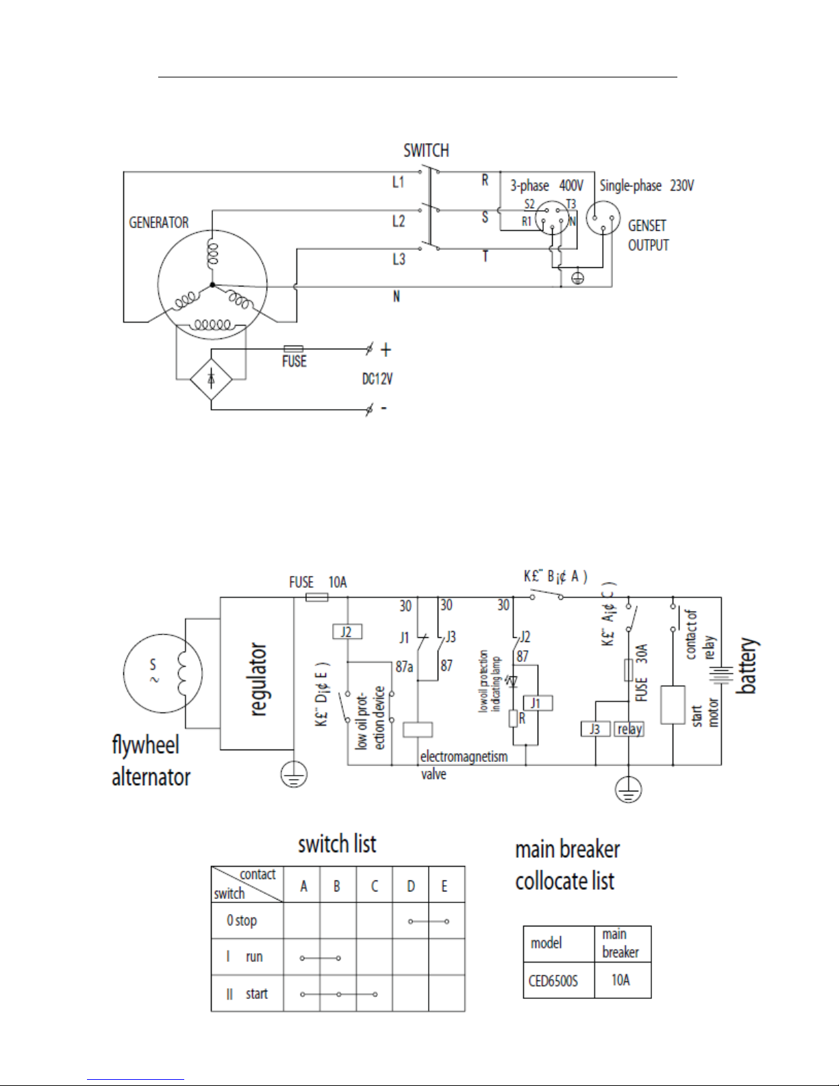
CALIFORNIA EMISSIONS CONTROL WARRANTY STATEMENT
Figure 5-3 three-phase circuit diagram
21
Page 22
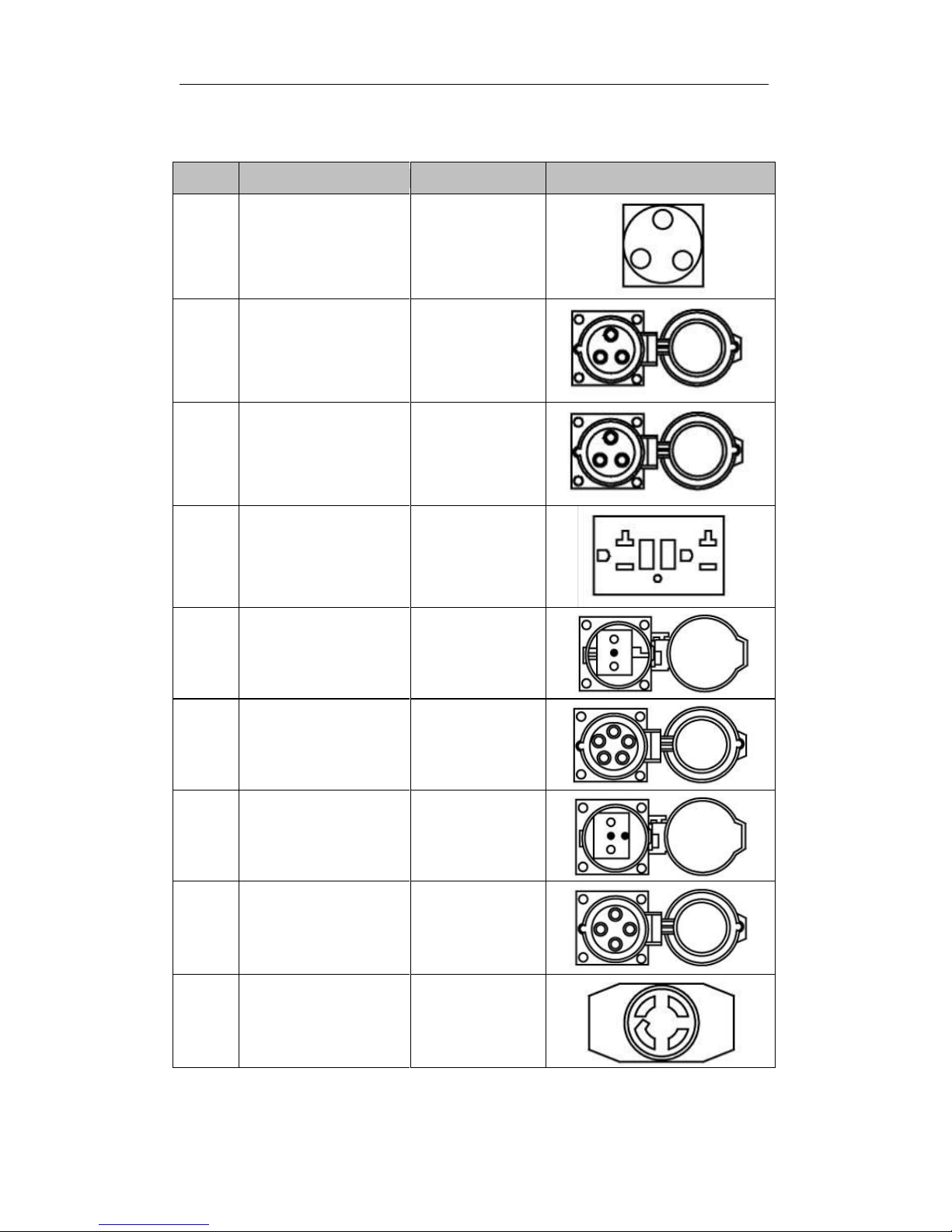
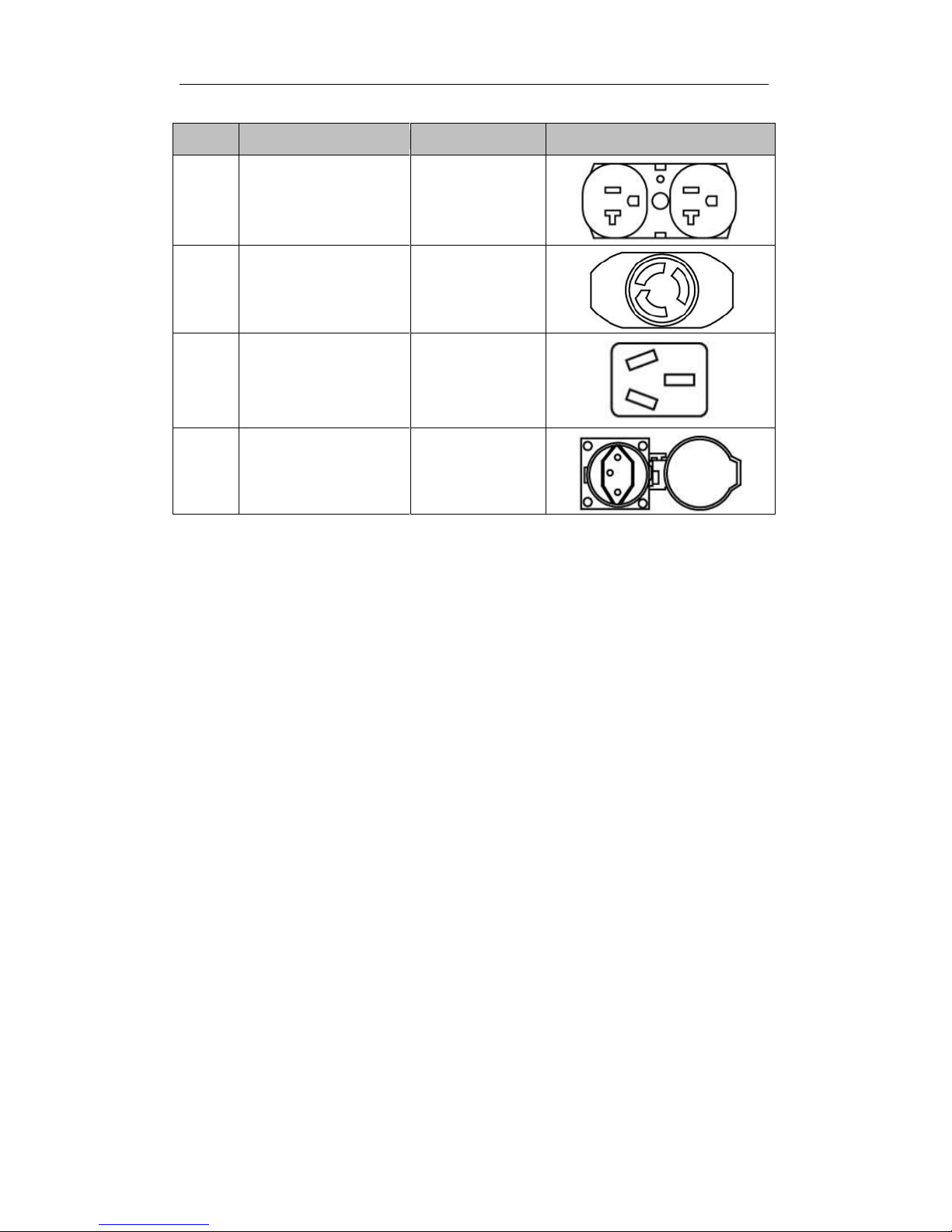
Appendix Ⅰ :Types of sockets
Code
Description
Specification
Picture
S01
S.A socket
25A, 250V
S02
British socket
32A, 240V
S03
British socket
16A, 240V
S04
Square American
type-socket
20A, 120V
S05
Germany socket
16A, 250V
S06
Three-phase five
holes socket
16A, 415V
S07
French socket
16A, 250V
S08
Three-phase four
holes socket
16A, 215V
S09
American type
4-hole unit loose
socket
30A, 250V
22
Page 23
Code
Description
Specification
Picture
S10
American double
socket
20A, 125V
S11
3-hole unit loose
socket
(UL-authentication
optional)
30A, 250V
S12
Australian socket
16A, 250V
S13
Swiss socket
10A, 250V
23
Page 24

Appendix Ⅱ :General power list of
appliance
To select the correct size generator for your needs you should make a list of
which tools and/or appliances you intend to operate with your generator. The
chart below contains approximate wattages and should give you an idea of the
size generator you will need. After you make your list of devices to be used, (be
sure to consider starting wattages) you will add the total watts and select the
generator that can supply that amount of power.
House Hold
Running Wattage
Requirements
Starting Wattage
Requirements
Coffee Maker
1750
1750
Dishwasher
1450
1800
Electric Fry Pan
1300
1300
Electric Range
6 Inch Elements
1500
1500
8 Inch Elements
2100
2100
Microwave Oven 625
watts
625
800
Refrigerator or Freezer
700
2200
Toaster 2-slice
1050
1050
Toaster 4- Slice
1650
1650
Automatic Clothes
Washer
1150
2300
Clothes Dryer Gas
700
1800
Dehumidifier
650
800
Electric Blanket (queen
size)
650
800
Garage Door Opener
¼hp
550
1100
Garage Door Opener
1/3 hp
725
1400
Furnace Fan 1/8 hp
500
1000
Furnace Fan 1/6 hp
750
1500
Furnace Fan ¼ hp
900
1800
Furnace Fan 1/3 hp
1000
1800
Furnace Fan½hp
1200
1500
Hair Dryer
300 - 1500
300 - 1500
Clothes Iron
1200
1200
Lights
As Indicated
As Indicated
Radio
50 - 200
50 - 200
Well or Sump Pump
1/3 hp
750
1500
Well or Sump Pump
1/2 hp
1000
2000
Well or Sump Pump 1
hp
2300
4500
Color Television 13 to
300
300
24
Page 25

House Hold
Running Wattage
Requirements
Starting Wattage
Requirements
32
VCR
50
50
Computer
150
150
Modem
25
25
Printer
100
100
Vacuum Cleaner
Upright
800
1100
Vacuum Cleaner
Canister
1100
1500
Central Air Conditioner
10.000 BTU
1500
2200
20.000 BTU
2500
3300
24.000 BTU
3800
4950
40.000 BTU
6000
7800
Air Compressor
½ hp
1000
2000
1 hp
1500
4500
1½hp
2200
6000
2 hp
2800
7700
Bench Grinder 6-inch
720
1000
Bench Grinder 8-inch
1400
2500
Bench Grinder 10-inch
1600
3600
Electric Cultivator 1/3
hp
700
1400
Electric Grass Trimmer
500
650
Drum Mixer ¼hp
700
1400
Mercury/Halogen
1000
1000
Floor Polisher
16-inch,¾hp
1400
3100
20-inch, 1hp
1600
4500
Hand Drill¼inch
350
350
Hand Drill 3/8 inch
400
400
Hand Drill½inch
600
600
Submersible
Water Pump 400gp
200
400
Water Pump
Centrifugal Type
500
650
Wet And Dry Vacuum
1.7 hp
900
900
2.5 hp
1300
1300
Saws
Worm Drive (chop saw)
1800
2600
Circular Saw 6½inch
800
1200
Circular Saw 7¼inch
1400
2300
25
Page 26

House Hold
Running Wattage
Requirements
Starting Wattage
Requirements
Circular Saw 8 ¼ inch
1800
3000
Electric Chain Saw
1100
1400
Table Saw 9 inch
1500
3000
Table Saw 10 inch
1800
4500
Electric Welder 70 amp
2800
2800
Band Saw
1100
1400
Electric Fence, 25
miles
250
250
Stock Tank De-Icer
1000
1000
Grain Cleaner
650
1000
Portable Conveyer½hp
1000
2400
Grain Elevator¾hp
1000
2400
Milk Cooler
1100
2300
Mixer 3½Cubic Feet
¾hp
2800
7700
Milking Machine, 2 hp
1100
2300
26
Page 27

PREFAZIONE
PREFAZIONE
La ringraziamo per aver scelto i prodotti della nostra azienda.
I manuali la aiuteranno ad azionare e manutenzionare correttamente i
prodotti. La invitiamo a leggere attentamente i manuali prima di azionare i
prodotti, in questo modo i generatori potranno lavorare nelle condizioni
migliori e godere di una lunga vita operativa.
I consumatori noteranno che questo manuale potrebbe differire
leggermente dal prodotto reale, questo perché abbiamo realizzato dei
miglioramenti sui nostri prodotti. Anche
alcune immagini nel manuale
potrebbero differire leggermente dal prodotto reale. Il produttore si
riserva il diritto di effettuare delle modifiche in qualunque momento
senza preavviso e senza incorrere in obblighi.
La pregiamo di notare il seguente
avviso.
Qualora l’uso dei prodotti non sia conforme con i manuali, sussiste il rischio
di lesioni personali e decesso.
È pertanto OBBLIGATORIO azionare i prodotti solo dopo aver letto
attentamente i manuali.
27
PR INDUSTRIAL s.r.l.
Loc. Il Piano
CAP 53031, Casole D’Elsa (SI)
ITALIA
Page 28

TAVOLA DEI CONTENUTI
TAVOLA DEI CONTENUTI
Capitolo 1 Specifiche Te cniche e Dati… … … ….4
1-1 Specifiche tecniche e dati………………… …… ……………4
1-2 Parametri operativi di base…………………………………………..6
1-3 Ingombro e informazioni generali dei generatori ………………6
1-4 Nome delle parti e pannello di controllo .…………………………….7
Capitolo 2 Azionare il generatore diesel ……………………….....4
2-1 Regole di sicurezza generale per l’azionamento del generatore 8
2-2 Preparazione prima della messa in funzione………………………9
2-3 Controllare la messa in funzione del motore diesel ……………..13
2-4 Avviamento del gruppo generatore ………………………………..13
2-5 Messa in funzione corretta del gruppo generatore ………………..14
2-6 Caricare………………………………………………………………15
2-7 Arresto del generatore ………………………………………………16
Capitolo 3 Manutenzione…………………………………………………..17
3-1Programma di manutenzione .........................................................17
3-2 Conservazione per lunghi periodi di tempo ……………………...19
Capitolo 4 Risoluzione dei problemi ………………………………….21
4-1 Procedure di risoluzione dei problemi ……………………………...21
4-2 Domande e dubbi ………………………………………….….21
Capitolo 5 Diagramma di circuito …………………………………….23
Appendice ⅠTipi di prese……………………………………………………..26
Appendice ⅡElenco generale delle applicazioni ...…………………………28
28
Page 29
SPECIFICHE TECNICHE E DATI
1
CAPITOLO1 SPECIFICHE TECNICHE
E DATI
1-1 Specifiche tecniche e dati
Tipo
Articolo
PMD 5000s
PMD 5000s
Generatore
Genere
monofase
trifase
Frequenza(Hz)
50
60
50
60
Potenza erogata
(KVA)
4.2
4.5
4.2
4.5
Voltaggio (A.C)(V)
220V,230V,240V,110/220V,120/240V,
115/230V
400/230V,420/240V,380/220V,
127/200V
Modalità di eccitazione
Autoeccitazione di tipo brushless o
Regolatore automatico di tensione
(AVR)
Regolatore automatico di
tensione (AVR)
Rivoluzione (r/min)
3000
3600
3000
3600
Voltaggio (D.C)(V)
12
Corrente (D.C)(A)
7
Livello di emissioni
acustiche dB(A)/7m
(0-100%load)
70-74
Fattore di potenza
cosφ
1
0.8
Gradi d’isolamento F B
Motore Diesel
Modello di potenza
CF186F (E)
Genere
A 4 tempi monocilindro raffreddato ad aria a iniezione diretta
Potenza max.
(kW/rpm)
6.5
8.6
6.5
8.6
Alesaggio x corsa
(mm)
86×70
Dislocamento del
cilindro (ml)
406
Sistema di
raffreddamento
Raffreddato ad aria
Sistema di
lubrificazione
Spruzzata a pressione, lubrificazione di tipo duplex
Volume di olio
lubrificante (L)
1.65
Sistema d’avviamento
Avviamento elettrico
Carburante
Diesel
Gruppo
Volume di carburante
nella tanica (L)
14.5
Protezione di bassa
pressione dell’olio
Presente
Peso totale (kg)
186
Ingombro complessivo
(mm)
920×520×700
Nota: la potenza indicata è raggiunta solo dopo 30 ore di avviamento iniziale.
29
Page 30
SPECIFICHE TECNICHE E DATI
1-2 Parametri operativi di base
1-2.1 Alle condizioni date, il generatore produrrà la potenza
specificata nella tabella in basso.
Tabella 1
Altezza sul livello del mare (m)
Temperatura ambiente
RH
0
+60°F (+20 oC)
60%
<3280.8ft (<1000 m)
41 – 104°F (5-40°C)
90%
cyriellemillion
1-3 Ingombro e informazioni generali dei
generatori
Si prega di fare riferimento alle specifiche per la corretta
dimensione dei diversi modelli.
30
Page 31

SPECIFICHE TECNICHE E DATI
1-4 Nome delle parti e pannello di controllo
1-4.1 Nome delle parti
Coperchio del serbatoio
Pannello di controllo
Etichetta
Silenziatore
(interno)
Batteria (interna)
Motore (interno)
Ruota
Sportello
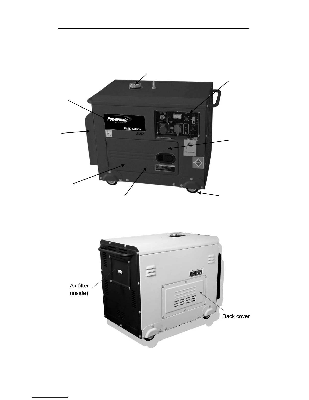
Coperchio
posteriore
Filtro dell’aria
(interno)
31
Page 32

AZIONARE IL GENERATORE DIESEL
1-4.2 Pannello di controllo
Pannello di controllo monofasico
Pannello di controllo trifasico
Spia di bassa
protezione
dell’olio (12V)
Voltmetro
99T1-300V
Connettore 7 contatti
Supporto 2P
dell’interruttore
Fusibile 10 A
Serracavo rosso
(107)
Serracavo nero
(107)
Bullone per
la messa a
terra
Presa 2P+T
230V 16A
Presa SCHUKO
230V 16A
Interruttore
dell’avviamento
elettrico
Spia di bassa
protezione
dell’olio (12V)
Voltmetro
99T1-300V
Connettore 7 contatti
Interruttore
dell’avviamento
elettrico
Supporto 2P
dell’interruttore
Fusibile 10 A
Serracavo nero
(107)
Serracavo rosso
(107)
Bullone per
la messa a
terra
Presa 2P+T
400V 16A
Presa 2P+T
230V 16A
32
Page 33

AZIONARE IL GENERATORE DIESEL
CAPITOLO 2 AZIONARE IL
GENERATORE DIESEL
2-1 Regole di sicurezza generale per
l’azionamento del gruppo generatore.
Per azionare il gruppo operatore in sicurezza, si prega di seguire
attentamente tutte le istruzioni fornite nel presente manuale. L'inosservanza delle
istruzioni potrebbe portare ad incidenti o danni all'attrezzatura.
2-1.1 Prevenzione degli incendi
Non utilizzare gasolio, cherosene o altri combustibili diversi dal diesel
leggero.
Tenere i carburanti infiammabili lontano dal generatore, poiché potrebbe
produrre scintille e dar fuoco ai gas.
Tenere il generatore diesel ad una distanza di almeno 1,5 metri dagli
edifici o da altra attrezzatura.
Azionare sempre il generatore diesel su una superficie piana.
2-1.2 Prevenzione dell’inalazione di gas di scarico.
Non inalare mai i gas di scarico emessi dal motore: contengono monossido di
carbonio tossico.
Non azionare mai il generatore in luoghi con scarsa ventilazione. Per azionare
questa apparecchiatura in locali chiusi, l’edificio dovrà necessariamente essere
dotato di un sistema di ventilazione adeguato che aspiri i gas di scarico.
2-1.3 Prevenzione di ustioni accidentali
Non toccare mai la marmitta e il suo rivestimento quando il motore diesel
è in funzione.
Non toccare mai la marmitta e il suo rivestimento dopo che il motore diesel
è stato usato, perché la marmitta resta calda a lungo.
2-1.4 Scossa elettrica e corto circuiti
Non toccare mai il generatore se questo è bagnato. Inoltre non toccare
mai il generatore con le mani bagnate.
Non azionare mai il generatore se le condizioni climatiche minacciano una
qualsivoglia precipitazione, come pioggia, neve o nebbia.
Per prevenire le scosse elettriche, il generatore dovrebbe essere messo a
terra. Fare riferimento alla fig. 2-1 prima di iniziare ad usare il generatore
elettrico.
Fig. 2-1
33
Page 34

AZIONARE IL GENERATORE DIESEL
NOTA
Quando si collegano i dispositivi al
generatore, assicurarsi che gli altri
dispositivi siano tarati a un livello
inferiore rispetto all'uscita del
generatore. Le prese del generatore non
vanno sovraccaricate oltre i limiti
regolati.
2-1.5 Altre istruzioni di sicurezza
Prima di azionare il generatore è raccomandabile che tutti gli operatori
sappiano come interrompere il circuito in caso di incidenti. Inoltre gli operatori
dovrebbero aver familiarizzato con tutti gli interruttori e le funzionalità del
generatore prima dell’uso. Quando si aziona il generatore, indossare delle
calzature antinfortunistiche e un abbigliamento idoneo. Tenere sempre bambini
e animali lontani dal generatore.
2-1.6 Batteria
Indossare una tuta di protezione quando si lavora con la batteria per
proteggere occhi, pelle e indumenti. Se si dovesse entrare in contatto con il
liquido elettrolitico, sciacquarsi immediatamente con acqua dolce. Inoltre, se il
liquido elettrolitico entra in contatto con gli occhi, sottoporsi immediatamente a
una visita medica.
2-2 Preparazione prima della messa in funzione
2-2.1 Scelta e trattamento del carburante
Utilizzare solo diesel leggero. In caso contrario sarà difficile avviare il
generatore.
Il carburante dovrebbe essere pulito e filtrato. Impedire l’ingresso di
polvere e acqua nel serbatoio per evitare di intasare i tubi del carburante e
gli ugelli dell'olio. Si potrebbe anche danneggiare la pompa di pressione.
Nota
È pericoloso far traboccare il serbatoio. Non superare mai l’asta di livello rossa
nel filtro.
Tipo
PMD 5000s
Il volume effettivo del serbatoio di
carburante:
14.5L
a. Dopo aver acquistato il carburante, porlo in un barile e farlo decantare per
3-4 giorni. In questo modo si depositeranno i granuli che altrimenti
otturerebbero i tubi del carburante.
b. 3-4 giorni dopo, inserire nella tanica metà asta di pompaggio del carburante
per non aspirare l’acqua e le impurità (che restano sul fondo del barile). Il
carburante contaminato accelera l’usura del sistema di alimentazione.
34
Page 35

AZIONARE IL GENERATORE DIESEL
NOTA
Non fumare mai vicino all’apertura del
serbatoio di carburante. Impedire che si
producano scintille vicino al carburante e
al serbatoio e non fare traboccare il
serbatoio. Dopo il rabbocco, stringere il
tappo del serbatoio.
2-2.2 Controllare e rabboccare l'olio del
motore
Accertarsi che il generatore si trovi su una
superficie piana e rimuovere l'asta di livello dai
motori. In caso contrario, il livello dell'olio che
viene mostrato sarà errato.
Controllare che il livello dell’olio si trovi tra il
limite massimo e il limite minimo. Se il motore è
nuovo o l’olio non è sufficiente, rabboccare il
motore con l’olio giusto (10W30).
Riporre l’asta di livello dell’olio nel foro per controllare il livello dell’olio.
Scegliere il giusto olio per il motore
L’olio del motore è il fattore più importante per determinare la vita operativa del
gruppo elettrogeno. Se si utilizza un olio di scarsa qualità o se non lo si cambia
regolarmente, il pistone e il cilindro si usureranno o s’ingripperanno in fretta.
Inoltre, la vita delle altre parti del motore, come i cuscinetti e le altre parti rotanti,
si accorcerà in maniera considerevole.
Asta di livello
Ogni 3 mesi o 200 ore
Intervallo per il cambio d’olio della macchina
Circa dopo 1 mese o 50 ore
35
Page 36

AZIONARE IL GENERATORE DIESEL
NOTA
Benché ci sia un sistema d’allarme che controlla la pressione bassa dell’olio, è
buona norma controllare la quantità d’olio presente nel motore. Se il livello
fosse troppo basso, rabboccare prima di avviare il motore.
Consigliamo di scaricare l’olio dal motore quando il motore diesel è ancora
caldo. Se il motore è freddo è più difficile scaricare tutto l'olio e alcune impurità
potrebbero restare all'interno del motore.
ATTENZIONE
NON rabboccare il motore con olio quando le macchine sono in funzione.
2-2.3 Controllare il filtro dell’aria
(1) Aprire il coperchio dei generatori, si
vedrà il gruppo del filtro.
(2) Allentare il dado ad alette del filtro
dell’aria, rimuovere il coperchio ed
estrarre il filtro dell’aria.
NOTA
Non lavare il filtro dell’aria con detergenti.
Cambiare il filtro dell’aria quando diminuiscono le prestazioni del motore o
se i gas di scarico hanno un brutto colore.
Non avviare mai il motore senza il filtro dell’aria installato, potrebbero
entrare oggetti estranei che danneggerebbero il motore.
(3) Dopo aver sostituito il filtro dell’aria, ricollocare il coperchio e stringere il
dado ad alette.
Se non s’installa immediatamente il filtro, la polvere nell’aria non sarà
riassorbita. In tal caso, consigliamo di bloccare il condotto dell’aria.
2-2.4 Controllare le condotte dell’olio
Un motore nuovo viene consegnato con l’olio e il carburante già scaricati.
Prima di avviare il motore, riempire il serbatoio di carburante e quello dell'olio.
Poi controllare che non ci siano bolle d’aria nel motore. In caso affermativo,
seguire la seguente procedura: allentare il dado di connessione tra la pompa
d’iniezione dell’olio e il tubo dell’olio e far sfiatare l’aria fino alla completa
eliminazione delle bolle. Infine ricollocare il dado di connessione e serrarlo.
2-2.5 Controllare i generatori
(1) Chiudere l’interruttore di potenza e disconnetterlo da ogni carico per non
provocare scosse elettriche, lesioni o morte.
Coperchio del filtro
36
Page 37

AZIONARE IL GENERATORE DIESEL
Knob handle
ATTENZIONE
Assicurarsi di chiudere l’interruttore di potenza.
Assicurarsi che i generatori siano messi a terra.
(2) Come utilizzare i generatori a doppio voltaggio
Spingere l’interruttore di voltaggio al voltaggio che s’intende usare.
ATTENZIONE
Assicurarsi che tutti i carichi siano sati disconnessi prima di avviare i
generatori. Altrimenti è molto pericoloso.
2-3 Controllare la messa in funzione del motore
diesel
2-3.1 Sistema d’allarme di bassa pressione.
I motori diesel sono dotati di un sensore d’allarme di bassa pressione che
spegne il motore se la pressione dell’olio scende troppo. Lo scopo di avere
questo sistema è assicurare che il motore non si blocchi. Se il livello dell'olio
nel motore è troppo basso, la temperatura dell'olio si alza troppo. Al contrario,
troppo olio rallenta il motore in maniera considerevole.
2-3.2 Come aprire il coperchio / sportello della scatola
(1) Aprire lo sportello della scatola: tirare la maniglia verso l’esterno e aprire.
Effettuare questi controlli quotidianamente.
(2) Allentare il bullone del coperchio esterno
del filtro dell’olio e del coperchio esterno
dell’ugello dell’olio, poi controllare il filtro
dell’aria.
(3) Controllare il coperchio esterno dell’ugello
dell’olio. Allentare il dado ad alette ed aprire
il coperchio esterno.
2-3.3 Rodaggio del motore
Quando si acquista un motore nuovo, è necessario rodarlo adeguatamente. Il
periodo di rodaggio è di circa 20 ore.
(1) Evitare il sovraccarico del motore quando è nuovo.
(2) Cambiare l’olio conformemente alle specifiche. In un motore nuovo, l’olio và
cambiato dopo circa 20 ore o tutti i mesi, mentre in un motore più vecchio l’olio
và cambiato ogni 100 ore o ogni tre mesi.
Il mancato rodaggio riduce la vita operativa del motore, la sua affidabilità e la
performance dei costi. In ultimo, anche la vita del generatore si accorcia.
Maniglia
37
Page 38

AZIONARE IL GENERATORE DIESEL
2-4 Avviamento del gruppo generatore
2-4.1 Avviamento.
(1) Assicurarsi che il generatore sia collocato su una SUPERFICIE PIANA O
UNIFORME. Se il motore s’inclina potrebbe fuoriuscirne del carburante.
(2) Disconnettere tutti i carichi elettrici dal generatore. Non avviare né arrestare
mai il generatore quando i dispositivi elettrici sono inseriti o accesi. In caso
contrario si possono generare dei corto circuiti e addirittura il guasto del
motorino d’avviamento.
(3) Girare la valvola del carburante su ON, altrimenti il carburante non sarà
sufficiente per avviare il generatore.
(4). Spingere la levetta di velocità in posizione “run”, in caso contrario il
generatore non si avvierà.
(5) Inserire la chiave di accensione in posizione “off”.
(6) Avviamento elettrico. Girare la chiave di accensione in posizione “start” e
aspettare che il motore si avvii, altrimenti sarà difficile da elettrizzare. (Se il
motore non si avvia entro cinque secondi, rilasciare la chiave e attendere per
almeno dieci secondi prima di effettuare un secondo tentativo. Se si continua
ad avviare il motore, questi si surriscalderà).
(7) Mentre il motore si scalda, muovere la chiave di accensione in posizione
“on”, altrimenti il carburante provocherà danni gravi.
2-4.2 Batteria
NOTA
Avviando lo starter troppo a lungo, la batteria potrebbe scaricarsi
eccessivamente e non fornire l’energia sufficiente ad un coretto avviamento del
motore.
Inoltre, quando il motore diesel è in funzione, è necessario lasciare la chiave in
posizione "ON".
NOTA IMPORTANTE
Tutte le quattro unità vengono dotate di batterie che non necessitano di
manutenzione. Non aggiungere acido di batteria.
2-5 Messa in funzione corretta del gruppo
generatore
2-5.1 Messa in funzione del motore diesel
1. Preriscaldare il motore diesel per 3 minuti a vuoto.
2. Prima controllare la spia di bassa pressione dell’olio sul pannello. Se la luce
è rossa, rabboccare l’olio.
3. Non regolare il bullone di regolazione del limite di velocità né il bullone di
regolazione del carburante. Questi bulloni sono stati configurati in ditta,
impostazioni diverse influiscono sulle prestazioni del motore.
38
Page 39

AZIONARE IL GENERATORE DIESEL
2-5.2 Controlli da effettuare durante il funzionamento del
motore
1. Controllare che non ci siano rumori anomali. Controllare spesso le giunzioni
dei condotti dell’olio, del carburante, dell’acqua e dell’aria per scoprire eventuali
perdite. In caso affermativo, eliminarle immediatamente per non causare danni
gravi.
2. Controllare che le prestazioni siano ottimali.
3. Controllare il colore dei gas di scarico (se sono troppo neri o troppo bianchi).
Qualora si riscontri una delle condizioni summenzionate, arrestare il motore e
scoprire la causa del problema. Se non si trovano problemi, contattare il
concessionario locale o il marchio della società più vicino.
2-6 Caricare
2-6.1 Connettere le cariche elettriche:
1. Collocare il motore in modo stabile e riscaldarlo per alcuni minuti dopo
l’avviamento.
2. Collegare e accendere nell’uscita di VOLTAGGIO CA desiderata le cariche
elettriche.
NOTA IMPORTANTE
NON collegare cariche trifase a un Generatore Diesel MONOFASE.
NON sovraccaricare il generatore.
Per prolungare la vita operativa del generatore e collegare correttamente le
applicazioni, raccomandiamo di seguire questi passaggi quando si aggiunge
carica elettrica:
3. Avviare il generatore SENZA CARICHE ELETTRICHE CONNESSE.
4. Far marciare il motore per alcuni minuti perché si STABILIZZI.
5. Collegare e accendere il primo pezzo. È preferibile collegare il pezzo prima
alla CARICA MAGGIORE.
6. Far stabilizzare il motore.
7. Collegare e accendere il secondo pezzo.
8. Far STABILIZZARE il motore.
9. Ripetere i passaggi 4 e 5 per ogni capacità durante l’aggiunta di cariche.
NOTA
Non avviare più di due dispositivi contemporaneamente. Ogni dispositivo
dovrebbe essere avviato da solo per evitare il sovraccarico del generatore.
Il generatore dovrebbe marciare a 3600 giri al minuto per raggiungere la
frequenza (60 Hz). La velocità del motore può essere regolata dal regolatore di
velocità.
39
Page 40

AZIONARE IL GENERATORE DIESEL
2-6.2 Uscita di elettricità
1. Aumentare i giri/minuto (girare la manopola di velocità al massimo) del
generatore per avere il massimo della potenza. In caso contrario, il
dispositivo regolatore automatico del voltaggio si ecciterà e, dopo un
periodo prolungato, potrebbe bruciare l'AVR. Per la velocità nominale del
generatore si prega di fare riferimento al Capitolo 1, punto 1-1 delle
specifiche tecniche e dati.
2. Osservare il puntatore del voltmetro, dovrebbe indicare il 5% del voltaggio
desiderato. Contemporaneamente portare l’interruttore in posizione GEN
(generatore). Il voltaggio CA della presa di alimentazione può essere in
uscita.
2-6.3 Caricare la batteria
1. Nello starter elettrico dei gruppi generatori, la batteria da 12V si ricarica
automaticamente attraverso il regolatore sul lato del motore mentre è in
funzione.
2. Se il generatore non viene utilizzato per periodi prolungati, la batteria
dovrebbe essere scollegata per evitare perdite d’energia della batteria.
3. Non collegare i terminali positivi e negativi della batteria
contemporaneamente. In questo modo si rischia di danneggiare la batteria e
causare gravi lesioni personali.
4. Non invertire le polarità durante l'attacco dei cavi alla batteria. In questo
modo si danneggerebbe sia la batteria che lo starter elettrico.
5. Quando si carica la batteria, questa produce gas infiammabili. Non fumare,
non provocare fiamme e scintille vicino alla batteria mentre si carica la
batteria perché si potrebbe provocare un incendio.
Per evitare le scintille durante la connessione dei cavi alla batteria, collegare
prima la batteria e poi il motore. Per scollegare i cavi della batteria, scollegare
prima il terminale motore del cavo.
2-7 Arresto del generatore
1. Per arrestare il generatore, rimuovere la carica elettrica.
2. Portare il contatore ad aria in posizione “off”, in caso contrario si verifica un
corto circuito.
3. Collocare la maniglia di velocità in posizione "RUN" e far marciare il motore
per 3 minuti dopo averlo scaricato. Non interrompere il motore diesel
immediatamente ma farlo raffreddare. Interrompendo improvvisamente il
motore si potrebbe alzare la temperatura in modo anomalo, bloccare l'ugello e
danneggiare il motore diesel.
40
Page 41

AZIONARE IL GENERATORE DIESEL
NOTA
1. Se non si riesce a interrompere il
motore con la carica, prima rimuovere
la carica e poi arrestare il motore.
2. Abbassare la maniglia del freno.
3. Se dotato di starter elettrico, girare
la chiave in posizione “Off”.
4. Portare la maniglia di velocità in
posizione "S".
4. Portare la chiave di accensione su “off”. I generatori si arresteranno.
5. Spostare la maniglia di velocità in posizione “stop” in modo da assicurare
l'interruzione del condotto del carburante.
6. Chiudere la valvola del carburante ma non bloccare il generatore chiudendo
il rubinetto del serbatoio qualora entrasse aria nel condotto del carburante
perché questo renderà più difficile il prossimo avviamento.
Maniglia
di
velocità
41
Page 42

MANUTENZIONE
CAPITOLO 3 MANUTENZIONE
3-1 Programma di manutenzione
Se si conserva il generatore in buono stato, gli si prolunga la vita operativa. È
necessario controllare ogni aspetto, compreso il motore diesel, il generatore, la
cabina di controllo e il telaio. Per le procedure di revisione, fare riferimento al
manuale d’istruzioni del relativo sottogruppo. In caso non si sia in possesso dei
predetti manuali, contattateci e ve ne invieremo uno.
Prima d’iniziare la manutenzione, assicurarsi che il motore diesel sia spento.
Fare riferimento alla tabella 3-1 per la corretta programmazione di
manutenzione.
Tabella 3-1. Programmazione di manutenzione per il gruppo generatore diesel
Scadenza
Pezzo
Tutti i giorni
Dopo 1
mese o
50 ore
Ogni 3 mesi o
200 ore
Ogni 6 mesi
o 400 ore
Una volta
all’anno o
ogni 1000
ore
Controllare e
rabboccare il
livello di
carburante
○Prima
dell’avviamento
Scaricare il
serbatoio
○
Controllare ed
eventualmente
rabboccare l’olio
nel motore
○
Pulire il filtro del
carburante
○
Controllare
eventuali perdite
di olio e
carburante
○dopo ogni
messa in
funzione
Controllare e
avvitare tutte le
parti fissate
○
●serrare il
bullone o la
testa del
cilindro
Controllare
l'iniettore
●
Controllare la pompa
ad iniezione
●
Controllare il
tubo del
carburante
●Cambiarlo
se
necessario
Controllare ed
eventualmente
rabboccare il
lubrificante nella
vaschetta di
recupero.
○Prima
dell’avviamento
Sostituire il
lubrificante
○la prima
volta
○la seconda
volta e quelle
successive
Pulire il filtro
dell’olio
○la prima
volta
○la seconda
volta e quelle
successive
Controllare il filtro
dell’aria
○la prima
volta
○la seconda
volta e quelle
successive
42
Page 43

MANUTENZIONE
Cambiare l’anima
del filtro dell’aria
Se danneggiato o macchiato, cambiarlo in tempo
Controllare ed
eventualmente
rabboccare il
livello del liquido
della batteria
○
Regolare il gioco
della valvola
d’ingresso e di
scarico
●la
prima
volta
●la seconda
volta e quelle
successive
Molare l’attacco
dell’ingresso e dello
scarico dell’aria
●
Cambiare l’anello
del pistone
●
Controllare la
spazzola elettrica e
l’anello scorrevole
●
Controllare la
resistenza
dell’isolamento
Il tempo d’interruzione è di oltre 10 giorni ○
Nota: il periodo di qualità dell'iniettore e della pompa d’iniezione è di 1500
ore o di due anni. Nella tabella,● significa che l’operazione richiede
attrezzi speciali o che i controlli possono essere realizzati dal
concessionario.
43
Page 44

MANUTENZIONE
Indicatore
Bullone di scarico
3-1.1 Cambio dell’olio del motore (ogni 100 ore)
Rimuovere il coperchio dell’olio. Rimuovere il
tappo di scarico dell’olio quando il motore è
ancora caldo. Fare attenzione all’olio caldo e al
motore caldo perché possono provocare ustioni. Il
bullone si trova nella parte inferiore del cilindro.
Dopo aver scaricato l’olio, ricollocare il bullone e
serrare, poi rabboccare con il carburante idoneo
fino al livello giusto.
3-1.2 Programma di manutenzione del filtro dell’aria
1. Pulire il filtro dell’aria ogni 6 mesi o dopo 500 ore di funzionamento.
2. Se necessario, cambiare il filtro.
3. Non utilizzare detergenti per pulire il filtro dell’aria.
NOTA
Non azionare mai il motore senza il filtro dell’aria. Potrebbe provocare gravi
danni al motore perché potrebbero entrare oggetti estranei nel sistema
d’ingresso. Cambiare sempre puntualmente il filtro dell’aria.
3-1.3 Manutenzione del filtro del carburante
1. Il filtro del carburante andrebbe pulito spesso per mantenere il
funzionamento del motore alle prestazioni massime.
2. Il periodo di tempo raccomandato per la pulizia del filtro del carburante è di 6
mesi o ogni 500 ore di funzionamento.
a. Per farlo, scaricare innanzitutto il carburante dal serbatoio.
b. Allentare le viti dal selettore del serbatoio e rimuovere il filtro dall’attacco.
Utilizzare il diesel per pulire il filtro del carburante. Inoltre, rimuovere l'iniettore
di carburante e pulirlo dei depositi di carbone. Il periodo di tempo consigliato
per farlo è ogni 3 mesi o 100 ore.
3-1.4 Tensione dei bulloni della testa del cilindro
I bulloni della testa del cilindro dovrebbero essere serrati conformemente alle
specifiche, fare riferimento al manuale del motore diesel per le specifiche e per
gli attrezzi speciali richiesti.
3-1.5 Controllo della batteria
Assicurarsi che l’acido della batteria sia pieno. Il motore utilizza una batteria
12V. A causa dei numerosi cicli d’inizio, l’acido della batteria può consumarsi.
Inoltre, prima del rabbocco, verificare che la batteria non sia danneggiata in
alcun modo. Aggiungere acqua distillata alla batteria durante il rabbocco.
Effettuare dei controlli sulla batteria una volta al mese.
44
Page 45

MANUTENZIONE
3-2 Conservazione per lunghi periodi di tempo
Se è necessario mettere via il generatore per lunghi periodi di tempo, si
dovrebbero realizzare le seguenti procedure.
1. Avviare il motore diesel per 3 minuti e poi interromperlo.
2. Quando il motore è ancora caldo, cambiare l'olio del motore con olio nuovo
di grado equivalente.
3. Per generatori con starter elettrico, premere la maniglia di decompressione e
avviare il motore per 2-3 secondi. Per farlo, portare l’interruttore dello starter su
“Start”. (Non avviare il motore diesel).
4. Pulire il motore e archiviarlo in un luogo asciutto.
45
Page 46

RISOLUZIONE DEI PROBLEMI
CAPITOLO 4 RISOLUZIONE DEI
PROBLEMI
4-1 Procedure di risoluzione dei problemi
Cause di malfunzionamento
Soluzione
Impossibile avviare il diesel.
Carburante insufficiente
Rabboccare il carburante
L’interruttore del carburante non
è su "OPEN".
Girare l’interruttore del carburante su
“OPEN”.
La pompa e l’ugello dell’alta
pressione non iniettano carburante
o la quantità iniettata è minore.
Smontare l’ugello e regolarlo sul banco
di prova.
La leva di controllo della velocità
non è su “RUN”.
Girare la leva di controllo su “RUN”.
Controllare il livello dell’olio di
lubrificazione.
La quantità standard di lubrificante
dovrebbe trovarsi tra la graduazione
alta “H” e la graduazione bassa “L”.
Non è veloce e potente nel tirare lo
starter reattivo.
Avviare il motore conformemente ai
requisiti delle “procedure di prima
messa in funzione”.
È presente sporcizia sull’ugello.
Pulire l’ugello.
L’accumulatore è privo di
elettricità.
Caricare l’accumulatore o cambiarlo.
Il generatore non genera elettricità
e non ha voltaggio di saldatura
L'interruttore principale (NFB) non
è acceso.
Girare la maniglia dell’interruttore
principale su “ON”.
La spazzola di carbone è usurato.
Il contatto è cattivo.
Cambiare la spazzola di carbone.
Il contatto della presa è cattivo.
Regolare il contatto della presa.
La rivoluzione nominale del motore
non viene raggiunta.
Far raggiungere la rivoluzione
nominale conformemente ai requisiti.
Il regolatore automatico AVR è
danneggiato.
Cambiarlo.
Il potenziometro di regolazione di
corrente per la saldatura elettrica è
danneggiato.
Cambiarlo.
Se dovessero ancora sussistere problemi, contattate il concessionario più
vicino o direttamente con la nostra società.
4-2 Domande e dubbi
1. Modello di generatore del motore diesel e il numero di serie del motore.
2. Stato di residenza.
3. Numero di ore di lavoro dell’attrezzatura e problema riscontrato.
4. Condizione dettagliata e momento in cui si è verificato il problema, in altre
parole, clima e atmosfera.
46
Page 47

DIAGRAMMA DI CIRCUITO
CAPITOLO 5 DIAGRAMMA DI CIRCUITO
Figura 5-1 diagramma di circuito a doppio voltaggio monofase
47
Page 48

DIAGRAMMA DI CIRCUITO
Figura 5-2 diagramma di circuito a singolo voltaggio monofase
48
Page 49

DIAGRAMMA DI CIRCUITO
Figura 5-3 diagramma di circuito trifase
49
Page 50

Appendice I: tipi di prese
Codice
Descrizione
Specifiche
Immagine
S01
presa S.A
25A, 250V
S02
Presa inglese
32A, 240V
S03
Presa inglese
16A, 240V
S04
Presa quadrata di
tipo americano
20A, 120V
S05
Presa tedesca
16A, 250V
S06
Presa trifase a
cinque fori
16A, 415V
S07
Presa francese
16A, 250V
S08
Presa trifase a
quattro fori
16A, 215V
S09
Presa americana a
quattro contatti
piatti
30A, 250V
50
Page 51

Codice
Descrizione
Specifiche
Immagine
S10
Doppia presa
americana
20A, 125V
S11
Presa a 3 contatti
piatti
(autenticazione UL
opzionale)
30A, 250V
S12
Presa australiana
16A, 250V
S13
Presa svizzera
10A, 250V
51
Page 52

Appendice II: Elenco generale di potenza
delle applicazioni
Per selezionare la dimensione corretta del generatore per ogni esigenza, è
necessario realizzare un elenco degli attrezzi e/o applicazioni che s’intende
azionare con il generatore. La tabella in basso contiene i watt approssimativi e
vuole fornire un’idea della dimensione del generatore necessario. Dopo aver fatto
un elenco di dispositivi da utilizzare (assicurarsi di considerare i watt iniziali)
aggiungere i watt totali e selezionare il generatore che può erogare quella
potenza.
Elettrodomestici
Potenza di lavoro
richiesta
Potenza iniziale
richiesta
Macchina del caffè
1750
1750
Lavapiatti
1450
1800
Friggitrice elettrica
1300
1300
Range elettrico
Elementi da 6 pollici
1500
1500
Elementi da 8 pollici
2100
2100
Microonde da 625 watt
625
800
Frigo o freezer
700
2200
Tostapane 2 fette
1050
1050
Tostapane 4 fette
1650
1650
Lavatrice automatica
1150
2300
Gas essiccatore di abiti
700
1800
Deumidificatore
650
800
Coperta elettrica
(matrimoniale)
650
800
Apriporta del garage ¼ hp
550
1100
Apriporta del garage 1/3 hp
725
1400
Ventola del forno 1/8 hp
500
1000
Ventola del forno 1/6 hp
750
1500
Ventola del forno ¼ hp
900
1800
Ventola del forno 1/3 hp
1000
1800
Ventola del forno ½hp
1200
1500
Phon
300 - 1500
300 - 1500
Ferro da stiro
1200
1200
Luci
Come da indicazioni
Come da indicazioni
Radio
50 - 200
50 - 200
Pompa per pozzi o per residui
1/3 hp
750
1500
Pompa per pozzi o per residui
1/2 hp
1000
2000
Pompa per pozzi o per residui
1 hp
2300
4500
TV a colori da 13 a 32
300
300
VCR
50
50
Computer
150
150
52
Page 53

Elettrodomestici
Potenza di lavoro
richiesta
Potenza iniziale
richiesta
Modem
25
25
Stampante
100
100
Aspirapolvere verticale
800
1100
Aspirapolvere con contenitore
1100
1500
Climatizzazione centralizzata
10.000 BTU
1500
2200
20.000 BTU
2500
3300
24.000 BTU
3800
4950
40.000 BTU
6000
7800
Compressore d’aria
½ hp
1000
2000
1 hp
1500
4500
1½hp
2200
6000
2 hp
2800
7700
Mola da banco 6 pollici
720
1000
Mola da banco 8 pollici
1400
2500
Mola da banco 10 pollici
1600
3600
Coltivatore elettrico 1/3 hp
700
1400
Tagliaerba elettrico
500
650
Miscelatore a tamburo ¼hp
700
1400
Mercurio/Alogena
1000
1000
Lucidatrice
16 pollici,¾ hp
1400
3100
20 pollici, 1hp
1600
4500
Menarola ¼ pollici
350
350
Menarola 3/8 pollici
400
400
Menarola ½ pollici
600
600
Macchina sommergibile
Pompa ad acqua 400gp
200
400
Pompa ad acqua di tipo a
centrifuga
500
650
Aspirapolvere e Aspiraliquidi
1.7 hp
900
900
2.5 hp
1300
1300
Seghe
Trasmissione a vite
(troncatrice)
1800
2600
Sega circolare 6½ pollici
800
1200
Sega circolare 7¼ pollici
1400
2300
Sega circolare 8 ¼ pollici
1800
3000
Segatrice elettrica a catena
1100
1400
Sega da tavolo 9 pollici
1500
3000
Sega da tavolo 10 pollici
1800
4500
Saldatrice elettrica 70 amp
2800
2800
53
Page 54

Elettrodomestici
Potenza di lavoro
richiesta
Potenza iniziale
richiesta
Sega a nastro
1100
1400
Recinzione elettrica, 25 miglia
250
250
Sbrinatore con serbatoio
1000
1000
Pulitore grani
650
1000
Trasportatore mobile ½hp
1000
2400
Elevatore per grani ¾hp
1000
2400
Raffreddatore di latte
1100
2300
Miscelatore 3½ Metri cubi
¾hp
2800
7700
Mungitrice, 2 hp
1100
2300
54
Page 55

PREFACIO
PREFACIO
Gracias por haber comprado los productos de nuestra empresa.
Los manuales le ayudarán a utilizar las máquinas y a llevar a cabo su
mantenimiento de manera correcta . Lea atentamente los manuales antes
de utilizar las máquinas . Así los generadores podrán funcionar en las
condiciones mejores prolongando su vida útil.
.Los usuarios podrían notar algunas diferencias en este manual
respecto al producto real, pero es algo debido a las mejoras hechas
en nuestros productos. Algunas de las imágenes
contenidas en este
manual también podrían ser ligeramente distintas del producto real.
El fabricante se reserva el derecho de llevar a cabo cualquier
modificación en cualquier momento sin previo aviso y sin incurrir en
ninguna obligación.
Fijarse en el siguiente símbolo de advertencia
.
Si las máquinas no se utilizan siguiendo las instrucciones contenidas en
estos manuales , podrían producirse heridas o incluso la muerte.
Por lo tanto, HAY que utilizar las máquinas solo después de haber
entendido completamente estos manuales.
55
PR INDUSTRIAL s.r.l.
Loc. Il Piano
CAP 53031, Casole D’Elsa (SI)
ITALIA
Page 56

ÍNDICE
ÍNDICE
Capítulo 1 Especificaciones y datos técnicos………………….1
1-1 Especificaciones y datos técnicos……………..……………………1
1-2 Parámetros de funcionamiento básico……….......………….……..2
1-3 Dimensiones y visión de conjunto generales de los
generadores...................................................................................2
1-4 Nombre de las partes y panel de mando……………………..…….3
Capítulo 2 Funcionamiento del generador diesel……….....4
2-1 Principales medidas de seguridad durante el funcionamiento del
generador……...............................................................................4
2-2 Preparación antes del uso………….....................……………..……5
2-3 Comprobación del funcionamiento del motor diesel………….…..8
2-4 Encendido del grupo generador……………...……………………..8
2-5 Funcionamiento correcto del grupo generador……………..……..9
2-6 Carga…………………………………………………………………10
2-7 Parada del generador………………………………………………11
Capítulo 3 Mantenimiento……………………………………………..12
3-1 Programas de mantenimiento……………………………………...12
3-2 Almacenamiento durante periodos de tiempo prolongados........13
Capítulo 4 Localización de averías……………………………….14
4-1 Procedimientos de localización de averías ..……………...14
4-2 Preguntas y dudas…………………………………………….….14
Capítulo 5 Diagrama del circuito………………………..…………….15
Apéndice ⅠTipo de enchufe……………………......…………………………..18
Apéndice ⅡLista general de la potencia de los aparatos….........…………20
56
Page 57

ESPECIFICACIONES Y DATOS TÉCNICOS
1
CAPÍTULO 1 ESPECIFICACIONES Y
DATOS TÉCNICOS
1-1 Especificaciones y datos técnicos
Tipo
Elemento
PMD 5000s
PMD 5000s
Generador
Tipo
Monofásico
Trifásico
Frecuencia (Hz)
50
60
50
60
Potencia nominal (KVA)
4,2
4,5
4,2
4,5
Tensión (C.A.)(V)
220V,230V,240V,110/220V,120/240V,
115/230V
400/230V,420/240V,380/220V,
127/200V
Modo de excitación
Autoexcitación sin escobillas o tensión
constante de autoexcitación (AVR)
Tensión constante de
autoexcitación (AVR)
Revoluciones (r/min.)
3000
3600
3000
3600
Tensión (C.C.)(V)
12
Corriente (C.C.)(A)
7
Nivel de ruido dB(A)/7m
(carga 0-100%)
70-74
Factor de potencia cosφ
1
0.8
Grado de aislamiento F B
Motor diesel
Modelo de potencia
CF186F (E)
Tipo
Inyección directa refrigerada por aire de 4 carreras y un cilindro
Potencia máx. (kW/rpm)
6,5
8,6
6,5
8,6
Calibre x carrera (mm)
86×70
Desplazamiento del cilindro
(ml)
406
Sistema de refrigeración
Refrigeración por aire forzado
Sistema de lubricación
Lubricación por salpicaduras de presión, de tipo dúplex
Volumen de aceite lubricante
(L)
1,65
Sistema de encendido
Encendido eléctrico
Carburante
Carburante diesel
Grupo
Volumen del tanque de
combustible (L)
14.5
Protección contra presión
aceite bajo
Presente
Peso total (kg)
186
Dimensiones totales (mm)
920×520×700
Nota: Llega a esta potencia solo después de 30 horas de funcionamiento.
57
Page 58

ESPECIFICACIONES Y DATOS TÉCNICOS
1-2 Parámetros de funcionamiento básico
1-2.1 Bajo estas condiciones, el generador producirá la
potencia especificada en la siguiente tabla.
Tabla 1
Altura sobre el nivel del mar
Temperatura ambiente
RH
0
+60°F (+20°C)
60%
<3280,8 ft (<1000 m)
41~104°F (5-40°C)
90%
1-3 Dimensiones y visión de conjunto
generales de los generadores
Consultar las especificaciones para las dimensiones correctas de
cada modelo.
58
Page 59

FUNCIONAMIENTO DEL GENERADOR DIESEL
1-4 Nombre de las partes y panel de mando
1-4.1 Nombre de las partes
Panel de
mando
Tapa del depósito de
combustible
Etiqueta
Motor
(interior)
Rueda
Puerta
Batería
(interior)
Silenciador
(interior)
Filtro del aire
(interior)
Tapa trasera
59
Page 60

FUNCIONAMIENTO DEL GENERADOR DIESEL
1-4.2 Panel de mando
Panel de mando monofásico
Panel de mando trifásico
Luz indicadora
protección nivel
aceite bajo (12V)
Voltímetro
99T1-300V
Soporte 2P del
disyuntor
Fusible 10 A
Soporte cable rojo
(107)
Soporte cable negro
(107)
Clavija
conexión a
tierra
Toma de SCHUKO
230V 16A
Toma 2P+T CEE
230V 16A
Botón de encendido
eléctrico
Conector de
7 pines
Luz indicadora
protección nivel
aceite bajo (12V)
Voltímetro
99T1-300V
Soporte 2P del
disyuntor
Fusible 10 A
Soporte cable rojo
(107)
Soporte cable negro
(107)
Clavija
conexión a
tierra
Toma de 2P+T CEE
230V 16A
Toma 2P+T CEE
230V 16A
Botón de encendido
eléctrico
Conector de
7 pines
60
Page 61

FUNCIONAMIENTO DEL GENERADOR DIESEL
CAPÍTULO 2 FUNCIONAMIENTO DEL
GENERADOR DIESEL
2-1 Medidas de seguridad generales durante el
funcionamiento del grupo generador.
Para utilizar el grupo generador de manera segura, seguir atentamente
todas las instrucciones contenidas en este manual. De lo contrario, podrían
producirse accidentes y/o daños en los equipos.
2-1.1 Prevención contra los incendios
No utilizar gasolina, queroseno u otros combustibles distintos del
combustible diesel ligero.
Mantener todos los combustibles inflamables alejados del generador
puesto que éste podría provocar chispas o prender estos gases.
Colocar el generador diesel a por lo menos 1,5 metros de distancia de
edificios y/u otros equipos.
Utilizar siempre el generador diesel en un lugar plano.
2-1.2 Prevención contra la inhalación de los gases de escape.
Nunca inhalar los gases de escape emitidos por el motor. Los gases de
escape contienen monóxido de carbono tóxico.
Nunca utilizar el generador en lugares donde la ventilación sea escasa. Para
poder utilizar este equipo en lugares cerrados, se necesita un sistema de
ventilación adecuado para el edificio que expulse hacia el exterior los gases de
escape venenosos.
2-1.3 Prevención contra las quemaduras accidentales
Nunca tocar el silenciador y su tapa cuando el motor diesel está
encendido.
Nunca tocar el silenciador y su tapa después de haber utilizado el motor
diesel, pues el silenciador se queda caliente durante un largo periodo de
tiempo.
2-1.4 Descargas eléctricas y cortocircuitos
Nunca tocar el generador si está mojado. Nunca tocar el generador con
las manos mojadas.
Nunca utilizar el generador si las condiciones meteorológicas prevén
cualquier tipo de precipitación como lluvia, nieve o niebla.
Para prevenir las descargas eléctricas, el generador tiene que estar
conectado a tierra. Remitirse a la Fig. 2-1 antes de empezar a utilizar el
generador eléctrico.
Fig. 2-1
61
Page 62

FUNCIONAMIENTO DEL GENERADOR DIESEL
NOTA
Cuando se conectan dispositivos al
generador, asegurarse de que estos
dispositivos tengan una potencia
nominal inferior a la potencia de los
generadores. Las tomas del generador
no deberían sobrecargarse más allá del
límite previsto.
2-1.5 Otras medidas de seguridad
Antes de utilizar el generador, todos los usuarios deberían saber cómo
interrumpir el circuito en caso de accidentes. Además, todos los usuarios
tendrían estar familiarizados con todos los interruptores y las funciones del
generador antes de utilizar esta máquina. Mientras se utiliza el generador,
llevar zapatos de seguridad y ropa adecuada. Mantener siempre a los niños y
a los animales lejos del generador.
2-1.6 Batería
Llevar equipos de protección cuando se trabaja con la batería para
protegerse los ojos, la piel, y llevar también la ropa adecuada. Si se entra en
contacto con el líquido electrolítico, lavarse inmediatamente con agua limpia.
Además, si el líquido electrolítico entra en contacto con los ojos, acudir
inmediatamente a un médico.
2-2 Preparación antes del uso
2-2.1 Elección y tratamiento del combustible
Utilizar solo combustible diesel ligero. De lo contrario, será difícil
conseguir encender el generador.
El combustible tendría que haber sido filtrado y estar limpio. Nunca dejar
que el polvo y el agua se mezclen con el combustible en el tanque del
combustible. De lo contrario, las tuberías de combustible y los inyectores
de aceite podrían atascarse. Podrían dañar también la bomba de presión.
Nota
Es peligroso llenar demasiado el tanque de combustible. Nunca sobrepasar el
pistón rojo en el filtro.
Tipo
PMD 5000s
Volumen efectivo del tanque de
combustible:
14,5L
a. Después de comprar el combustible, colocarlo dentro de un bidón y
dejarlo allí durante 3-4 días. De lo contrario, contendrá unos gránulos que
atascarán las tuberías de combustible.
b. Después de 3-4 días, insertar la ventosa de aspiración de combustible hasta
llegar a la mitad del bidón (el agua y las impurezas se quedan en la parte
62
Page 63

FUNCIONAMIENTO DEL GENERADOR DIESEL
inferior del bidón). De lo contrario, podrían aspirarse también esas partículas.
El combustible contaminado causaría el desgaste acelerado de las piezas del
sistema del combustible.
NOTA
Nunca fumar cerca de la abertura del
tanque de combustible. No dejar que las
chispas se acerquen al combustible ni al
tanque de combustible ni llenar
demasiado el tanque. Después del
llenado, apretar la tapa del
combustible.
2-2.2 Comprobación y llenado del aceite
del motor
Asegurarse de que el generador esté colocado
sobre una superficie plana y quitar la varilla del
aceite del motor. De lo contrario, el nivel de
aceite mostrado no será el correcto.
Comprobar si el nivel de aceite se encuentra
entre el límite máximo y el límite mínimo. Si el
motor es nuevo o el aceite no es suficiente,
llenar el motor con el aceite para motor adecuado (10W30).
Volver a poner en su sitio la varilla del aceite en el agujero para
comprobar el nivel de aceite del motor.
Elección del aceite para motores adecuado
El aceite del motor es el factor más importante para determinar la vida del
motor del generador. Si se utiliza un aceite para motores de mala calidad o si
no se cambia el aceite con regularidad, el pistón y el cilindro se desgastarán
fácilmente o se agarrotarán. Además, la vida de las otras partes del motor
como los cojinetes, y las demás piezas giratorias se acortará
considerablemente.
Inicio
Varilla del aceite
63
Page 64

FUNCIONAMIENTO DEL GENERADOR DIESEL
NOTA
Aunque exista un sistema de alarma que comprueba la presión de aceite bajo,
siempre es útil controlar la cantidad de aceite dentro del motor. Si el nivel de
aceite es bajo, añadir más antes de encender el motor.
Un buen momento para vaciar el aceite del motor es cuando el motor está aún
caliente. Si el motor está totalmente frío, será más difícil vaciar todo el aceite o
algunas impurezas podrían quedarse dentro del motor.
ADVERTENCIA
NO llenar de aceite el motor cuando las máquinas están funcionando.
2-2.3 Comprobación del filtro del
aire
(1) Abrir la tapa de los generadores, así
será posible ver el filtro del aire completo.
(2) Aflojar la tuerca de mariposa del filtro
del aire, quitar la tapa del filtro del aire y
sacarlo.
NOTA
No utilizar detergentes para lavar el filtro del aire.
Cuando el rendimiento del motor disminuye o cuando el color de los
gases de escape es malo, sustituir el filtro.
Nunca encender el motor con el filtro del aire puesto porque podrían
Tapa del filtro del aire
Cada 3 meses o 200 horas
Intervalo de cambio del aceite de la máquina
Aproximadamente 1 mes o 50 horas
Start
64
Page 65

FUNCIONAMIENTO DEL GENERADOR DIESEL
Knob handle
entrar objetos extraños que dañarían el motor.
(3) Después de sustituir el filtro del aire, volver a colocar la tapa y apretar bien
la tuerca de mariposa.
Si no se vuelve a colocar inmediatamente el filtro del aire, el polvo contenido
en el aire entrará dentro del motor. En este caso, sería oportuno bloquear el
paso de aire.
2-2.4 Comprobación del paso del aceite
Antes de vender un motor nuevo, éste se vacía del combustible y del aceite.
Antes de encender el motor, llenar el tanque del combustible y el aceite del
motor. Luego, comprobar si hay burbujas de aire en el motor. Si las hay, llevar
a cabo las siguientes operaciones: aflojar la tuerca de conexión entre la bomba
de inyección del aceite y la tubería del aceite; dejar salir el aire del sistema
hasta que no haya más burbujas; luego volver a colocar la tuerca de conexión
y apretarla.
2-2.5 Comprobación de los generadores
(1) Apagar el interruptor de alimentación y desconectarlo de cualquier carga.
De lo contrario, podrían producirse descargas eléctricas e incluso heridas y
muerte.
ADVERTENCIA
Asegurarse de apagar el interruptor de alimentación.
Asegurarse de haber conectado a tierra los generadores.
(2) Cómo utilizar generadores de tensión doble
Poner el conmutador de tensión sobre la tensión que se quiere usar.
ADVERTENCIA
Asegurarse de desconectar cualquier carga antes de encender los
generadores. De lo contrario, sería muy peligroso.
2-3 Comprobación del funcionamiento del motor
diesel
2-3.1 Sistema de alarma de presión baja.
Los motores diesel tienen un sistema de sensor de baja presión, en caso de
que la presión de aceite se vuelva demasiado baja, el sensor apaga el motor.
El objetivo de este sistema es asegurar que el motor no se agarrote. Si dentro
del motor no hay suficiente aceite, la temperatura del aceite aumentará
demasiado. Al contrario, si dentro del motor hay demasiado aceite, el aceite
del motor puede reducir considerablemente la velocidad del motor.
2-3.2 Cómo abrir la puerta de la cubierta/tapa
(1) Abrir la puerta de la cubierta: Tirar del pomo hacia fuera y abrir la puerta.
Llevar a cabo estos controles cada día.
(2) Aflojar el tornillo de la tapa exterior del
filtro del aire y la tapa exterior del inyector de
aceite, y luego comprobar el filtro del aire.
65
Page 66

FUNCIONAMIENTO DEL GENERADOR DIESEL
(3) Comprobar la tapa exterior del inyector de aceite. Aflojar la tuerca de
mariposa y abrir la tapa exterior.
2-3.3 Rodaje del motor
Cuando se compra un motor salido de fábrica, hay que hacerle el rodaje
correcto. El periodo de rodaje es de unas 20 horas.
(1) Evitar sobrecargar el motor salido de fábrica
(2) Cambiar el aceite del motor según las especificaciones. El cambio de
aceite en un motor salido de fábrica se lleva a cabo aproximadamente cada
20 horas o cada mes, mientras en un motor más viejo, se lleva a cabo
aproximadamente cada 100 horas o tres meses.
Si el motor no se somete a rodaje, esto reducirá su vida útil, su fiabilidad y su
rentabilidad. Por fin, se acortará también vida del generador.
2-4 Encendido del grupo generador
2-4.1 Encendido.
(1) Asegurarse de que el generador se encuentre en una superficie " PLANA "
o " NIVELADA ". Si el motor está inclinado, el combustible podría derramarse.
(2) Desconectar todas las cargas eléctricas del generador. Nunca encender y
apagar el generador con dispositivos eléctricos enchufados o encendidos. De
lo contrario, se producirá un cortocircuito, e incluso la avería del motor de
arranque.
(3) Poner la válvula del combustible en posición " ON ". De lo contrario, el
combustible no será suficiente para encender el generador.
(4). Poner el nivel de velocidad en posición " run ". De lo contrario, el
generador no se encenderá.
(5) Insertar la llave de encendido en posición “ off ”.
(6) Encendido eléctrico: girar la llave de encendido en posición " Start " y
dejarla así hasta que el motor se encienda. De lo contrario, su electrificación
será anormal. (Si el motor no se enciende en cinco segundos, soltar la llave y
esperar por lo menos diez segundos antes de intentar encender de nuevo el
motor. Si se mantiene en posición de encendido, el motor se calentará.)
(7) Si el motor se calienta, poner la llave de encendido en posición " on ". De lo
contrario, el paso de combustible causará problemas graves.
2-4.2 Batería
NOTA
Si se hace funcionar el motor de arranque durante demasiado tiempo, la
batería podría agotarse demasiado como para proporcionar suficiente energía
para el encendido correcto del motor.
Además, cuando el motor diesel está funcionando, dejar la llave en posición
“ON”.
Pomo
66
Page 67

FUNCIONAMIENTO DEL GENERADOR DIESEL
NOTA IMPORTANTE
Todas las unidades vienen con una batería gratuita para el mantenimiento. No
hace falta añadir ningún ácido para baterías.
2-5 Funcionamiento correcto del grupo
generador
2-5.1 Funcionamiento del motor diesel
1. Precalentar el motor diesel durante 3 minutos sin carga.
2. Primero, controlar la luz indicadora de presión de aceite bajo en el panel. Si
la luz es de color rojo, añadir más aceite.
3. No ajustar el tornillo de regulación del límite de velocidad ni el tornillo de
regulación del combustible. Estos tornillos ya han sido ajustados en fábrica, si
se cambia su posición, esto afectará las propiedades de rendimiento del motor.
2-5.2 Comprobaciones durante el funcionamiento del motor
1. Comprobar si hay ruidos anormales. Controlar con frecuencia la junta de
paso del aceite, del combustible, del agua y del aire para ver si hay escapes.
Si hubiera uno, solucionar enseguida el problema. De lo contrario, podrían
producirse problemas graves.
2. Comprobar si el rendimiento es bueno o malo.
3. Comprobar el color de los gases de escape (si son demasiado negros o
demasiado blancos).
Si se produce una de estas condiciones, parar el motor y buscar la causa del
problema. Si no se encuentra ningún problema, contactar con el distribuidor
local o con nuestra sucursal más cercana.
2-6 Carga
2-6.1 Conexión de las cargas eléctricas:
1. Dejar el motor estable y caliente durante unos minutos después del
encendido.
2. Conectar y encender la salida de TENSIÓN CA deseada con las cargas
eléctricas.
NOTA IMPORTANTE
NO conectar cargas trifásicas a un generador diesel MONOFÁSICO.
NO sobrecargar este generador.
Para prolongar la vida del generador y conectar correctamente los dispositivos,
seguir estos pasos para añadir carga eléctrica:
3. Encender el generador sin CARGA ELÉCTRICA CONECTADA.
4. Dejar que el motor funcione durante varios minutos para ESTABILIZARSE.
67
Page 68

FUNCIONAMIENTO DEL GENERADOR DIESEL
5. Conectar y encender el primer elemento. Es mejor conectar primero el
elemento de CARGA MAYOR.
6. Dejar que el motor se estabilice.
7. Conectar y encender el elemento siguiente.
8. Dejar que el motor se ESTABILICE.
9. Repetir los pasos 4-5 para cada capacidad cuando se añaden cargas.
2-6.2 Potencia de salida de la electricidad
1. Aumentar las revoluciones por minuto (girar el control de la velocidad hasta
el máximo) del generador para conseguir la potencia máxima del generador.
De lo contrario, el dispositivo de regulación automática de la tensión se
excitará y haciéndolo durante largos periodos de tiempo, causaría el
quemado del AVR. Para la velocidad nominal del generador, remitirse al
Capítulo 1, apartado 1-1 Especificaciones y datos técnicos.
2. Observar la aguja del voltímetro, debería apuntar hacia la tensión
necesitada 5%. Mientras tanto, poner el conmutador en la posición GEN
(generador). Será posible producir tensión CA desde el enchufe de la
alimentación.
2-6.3 Carga de la batería
1. En el caso de los motores de arranque eléctrico de los grupos generadores,
la batería de 12V se carga automáticamente a través del regulador situado
en la parte lateral del motor durante el funcionamiento.
2. Si no se va a utilizar el generador durante largos periodos de tiempo, la
batería debería desconectarse para evitar que pierda su energía.
3. No conectar los terminales negativos y positivos de la batería juntos al
mismo tiempo. De lo contrario, la batería se dañará y causará heridas
graves.
4. No invertir las polaridades cuando se conectan los cables de la batería. De
lo contrario, se dañará la batería y también el motor de arranque eléctrico.
5. Cuando se carga la batería, ésta produce gases inflamables. No fumar,
acercar llamas ni chispas a la batería mientras se está cargando, porque
podría causar un incendio.
Para evitar la producción de chispas mientras se conectan los cables a la
batería, primero conectar los cables a la batería y luego al motor. Para
desconectar los cables de la batería, primero desconectar el extremo del cable
conectado al motor.
NOTA
No encender más de dos dispositivos al mismo tiempo. Hay que encender los
dispositivos de uno en uno para evitar que el generador se sobrecargue.
El generador debería funcionar a 3600 revoluciones por minuto para alcanzar
la frecuencia (60 Hz). La velocidad del motor se puede ajustar desde el
regulador de velocidad.
68
Page 69

FUNCIONAMIENTO DEL GENERADOR DIESEL
2-7 Apagado del generador
1. Quitar la carga eléctrica del generador cuando se quieren apagar los
generadores.
2. Desplazar el conmutador del aire en posición “off”. De lo contrario, se
producirá un cortocircuito.
3. Poner el mando de la velocidad en la posición “RUN” y dejar funcionar el
motor durante unos 3 minutos después de la descarga. No apagar
inmediatamente el motor diesel, dejar que se enfríe. Si se apaga
inmediatamente el motor diesel, la temperatura del motor podría aumentar de
manera anormal, bloquear el inyector y dañar el motor diesel.
NOTA
1. Si no se puede apagar el motor con
una carga, primero quitar la carga y
luego apagar el motor.
2. Presionar el mando del freno.
3. Si está equipado con un motor de
arranque eléctrico, girar la llave hacia
la posición “Off”.
4. Poner el mando de la velocidad en
posición “S”.
4. Poner la llave de encendido en posición “off”. Así los generadores se
apagarán.
5. Desplazar el mando de la velocidad hacia la posición “stop”, esto asegurará
la interrupción del paso de combustible.
6. Cerrar la válvula del combustible, pero no parar el generador cerrando la
llave de paso del tanque de combustible porque el aire entraría en las tuberías
del combustible causando problemas al encendido siguiente.
Mando de
la velocidad
69
Page 70

MANTENIMIENTO
CAPÍTULO 3 MANTENIMIENTO
3-1 Programas de mantenimiento
Si se lleva a cabo un buen mantenimiento del generador, esto prolongará su
vida útil. Hay que controlarlo todo incluido el motor diesel, el generador, el
armario de mandos y el armazón. Para los procedimientos de revisión,
remitirse al manual de instrucciones del relativo subconjunto. Para solicitar estos
manuales, llamar nuestra empresa y nosotros nos ocuparemos de
proporcionarlos.
Antes de empezar las operaciones de mantenimiento, asegurarse de haber
apagado el motor diesel.
Remitirse a la Tabla 3-1 para el programa de mantenimiento correcto.
Tabla 3-1. Programa de mantenimiento del grupo generador diesel
Cuándo
Operación
Cada día
Después
de 1 mes
o 50
horas
Cada 3 meses o
200 horas
Cada 6
meses o 400
horas
Cada año
o 1000
horas
Comprobación del
nivel del
combustible y
llenado
○ Antes
del
encendido
Vaciado del
tanque de
combustible
○
Comprobación del
nivel de aceite del
motor y llenado
○
Limpieza del filtro
de combustible
○
Control escapes
de aceite y
combustible
○
Después
de cada
utilización
Comprobación y
atornillado de
todas las piezas
por apretar
○
● apretar bien
el tornillo de la
culata
Comprobación del
inyector
●
Comprobación de
la bomba de inyección
●
Comprobación de
la tubería del
combustible
● Sustituir si
necesario
Comprobación del
nivel del aceite lubricante
y llenado
○ antes
del
encendido
Sustitución del
aceite lubricante
○ al
primer
uso
○ al segundo uso
y siguientes
Limpieza del filtro
del aceite
lubricante
○ al
primer
uso
○ al segundo uso
y siguientes
Comprobación del
elemento de
limpieza del aire
○ al
primer
uso
○ al segundo uso
y siguientes
70
Page 71

MANTENIMIENTO
Sustitución del
centro del filtro del
aire
Si está dañado o manchado, sustituirlo en cualquier momento
Comprobación del
nivel del líquido
de la batería y
llenado
○
Ajuste de la entrada
y desahogo de la
válvula de escape
● al
primer
uso
● al segundo
uso y
siguientes
Amolado de la
entrada de aire y la
compuerta del aire
de escape
●
Sustitución del
segmento de pistón
●
Comprobación de
la escobilla
eléctrica y de la
anilla de
deslizamiento
●
Comprobación de
la resistencia de
aislamiento
El tiempo de parada es de más de 10 días ○
Nota: el periodo de calidad del inyector y de la bomba de inyección es de
1500 horas o dos años. El símbolo ● significa que hay que utilizar
herramientas específicas, o que es algo que puede comprobar el
distribuidor.
71
Page 72

MANTENIMIENTO
Varilla
Tornillo
3-1.1 Sustitución del aceite del motor (cada 100 horas)
Quitar la tapa del aceite. Quitar el tapón de
vaciado del aceite mientras el motor diesel está
todavía caliente. Tener cuidado con el aceite y el
motor caliente porque existe la posibilidad de
quemarse. El tornillo está situado en la parte
inferior del cilindro. Después de vaciar el aceite,
volver a poner el tornillo y apretarlo. Luego llenar
con el aceite para motores correcto hasta el nivel
adecuado.
3-1.2 Programa de mantenimiento del filtro de aire
1. Limpiar el filtro de aire cada 6 meses o 500 horas de funcionamiento.
2. Si fuera necesario, sustituirlo.
3. No utilizar detergentes para limpiar el filtro de aire.
NOTA
Nunca encender el motor sin el filtro de aire puesto. Esto podría causar daños
graves al motor porque en el sistema de entrada podrían penetrar objetos
extraños. Sustituir siempre el filtro de aire puntualmente.
3-1.3 Mantenimiento del filtro de combustible
1. El filtro de combustible debería limpiarse a menudo para que el motor
funcione con su rendimiento máximo.
2. El periodo de tiempo recomendado para limpiar el filtro de combustible es
cada 6 meses o 500 horas de funcionamiento.
a. Para llevar a cabo el mantenimiento, primero vaciar el tanque de
combustible.
b. Aflojar los pequeños tornillos del interruptor de combustible y quitar el filtro
de combustible de su alojamiento. Utilizar combustible diesel para limpiar el
filtro de combustible. Además, quitar el inyector de combustible y limpiar los
residuos de carbón a su alrededor. El periodo de tiempo recomendado para
llevar a cabo esta operación es cada 3 meses o 100 horas.
3-1.4 Tensiones del tornillo de la culata
Los tornillos de la culata deberían apretarse según las especificaciones.
Remitirse al manual del motor diesel para las especificaciones y las
herramientas específicas necesarias para el apriete.
3-1.5 Comprobación de la batería
Asegurarse de que la batería esté llena de ácido. El motor usa una batería de
12V. A causa de los numerosos ciclos de encendido, el ácido de la batería
podría agotarse. Además, antes de llenarlo, comprobar que la batería no esté
dañada. Añadir agua destilada en la batería durante el llenado. Controlar la
batería una a mes.
72
Page 73

MANTENIMIENTO
3-2 Almacenamiento durante periodos de tiempo
prolongados
Si hay que almacenar el generador durante periodos de tiempo prolongados,
hay que llevar a cabo las siguientes operaciones:
1. Encender el motor diesel durante 3 minutos y luego detenerlo.
2. Con el motor aún caliente, sustituir el aceite del motor con otro nuevo del
grado adecuado.
3. Para los generadores con motor de arranque eléctrico, apretar el mando de
descompresión y hacer arrancar el motor durante 2-3 segundos. Para hacerlo,
poner el interruptor del motor de arranque en posición “Start”. (No encender el
motor diesel)
4. Limpiar el motor y guardarlo en un lugar seco.
73
Page 74

LOCALIZACIÓN DE AVERÍAS
CAPÍTULO 4 LOCALIZACIÓN DE
AVERÍAS
4-1 Procedimientos de localización de averías
Causa de la avería
Solución
El motor diesel no se puede encender.
La cantidad de combustible no es
suficiente
Añadir más combustible
El conmutador de combustible no
está en la posición “OPEN”.
Poner el conmutador de combustible
en posición “OPEN”.
La bomba de alta presión y el
inyector no inyectan combustible
o la cantidad inyectada es
inferior.
Desmontar el inyector y ajustarlo en
la mesa de ensayo.
La palanca de control de
velocidad no está en la posición
“RUN”.
Poner la palanca de control de
velocidad en posición “RUN”.
Comprobar el nivel del aceite
lubricante.
La cantidad estándar de aceite
lubricante debería estar entre el
nivel máximo “H” y el nivel mínimo
“L”.
No es lo suficiente rápido y
potente para arrancar el motor de
arranque reactivo.
Encender el motor diesel de
conformidad con los
“procedimientos de encendido”.
El inyector está sucio.
Limpiar el inyector.
La electricidad no llega al
acumulador.
Cargar el acumulador o sustituirlo.
El generador no puede generar
electricidad y no tiene tensión en trabajo
El interruptor principal (NFB) no
está encendido.
Poner el interruptor principal en
posición “ON”.
La escobilla de carbón del
generador está desgastada. El
contacto es malo.
Sustituir la escobilla de carbón.
El contacto del enchufe es malo.
Ajustar los pies de contacto del
enchufe.
No es posible alcanzar las
revoluciones nominales del
motor.
Hacer que alcance las revoluciones
nominales de conformidad con los
requisitos.
El regulador automático de AVR
está dañado.
Sustituirlo.
El potenciómetro de regulación
de corriente de la soldadura
eléctrica está dañado.
Sustituirlo.
Si los problemas persisten, contactar con el distribuidor más cercano o
directamente con nuestra empresa, si fuera necesario.
74
Page 75

LOCALIZACIÓN DE AVERÍAS
4-2 Preguntas y dudas
1. Modelo de generador del motor diesel y número de modelo del motor.
2. País de residencia.
3. Número de horas de funcionamiento del equipo junto al tipo de problema detectado.
4. Descripción detallada de las condiciones y del tiempo existentes cuando se
ha producido el problema, es decir, clima y atmósfera.
75
Page 76

DIAGRAMA DEL CIRCUITO
CAPÍTULO 5 DIAGRAMA DEL CIRCUITO
Figura 5-1 diagrama del circuito de doble tensión monofásico
76
Page 77

DIAGRAMA DEL CIRCUITO
Figura 5-2 diagrama del circuito de tensión única monofásico
77
Page 78

DIAGRAMA DEL CIRCUITO
Figura 5-3 diagrama del circuito trifásico
78
Page 79

Apéndice Ⅰ :Tipos de enchufe
Código
Descripción
Especificaciones
Dibujo
S01
Enchufe África del
sur
25A, 250V
S02
Enchufe inglés
32A, 240V
S03
Enchufe inglés
16A, 240V
S04
Enchufe cuadrado
de tipo americano
20A, 120V
S05
Enchufe alemán
16A, 250V
S06
Enchufe de cinco
agujeros trifásico
16A, 415V
S07
Enchufe francés
16A, 250V
S08
Enchufe de cuatro
agujeros trifásico
16A, 215V
S09
Enchufe libre de
cuatro agujeros de
tipo americano
30A, 250V
79
Page 80

Código
Descripción
Especificaciones
Dibujo
S10
Enchufe
americano doble
20A, 125V
S11
Enchufe libre de
tres agujeros
(UL-autenticación
opcional)
30A, 250V
S12
Enchufe
australiano
16A, 250V
S13
Enchufe suizo
10A, 250V
80
Page 81

Apéndice Ⅱ :Lista general de la potencia
de los aparatos
Para seleccionar el generador de tamaño correcto para sus necesidades, debería
hacer una lista de las herramientas y/o aparatos que tiene intención de hacer
funcionar con su generador. La tabla aquí abajo contiene los vatajes
aproximados y debería darle una idea del tamaño de generador que necesita.
Después de hacer su lista de dispositivos (asegúrese de considerar los vatajes de
encendido), calculará los vatios totales y seleccionará el generador que puede
proporcionarle esa cantidad de energía.
Electrodoméstico
Requisitos de vataje de
funcionamiento
Requisitos de
vataje de
encendido
Máquina de café
1750
1750
Lavavajillas
1450
1800
Freidora
1300
1300
Gama eléctrica
Elementos de 6 pulgadas
1500
1500
Elementos de 8 pulgadas
2100
2100
Horno microondas de 625
vatios
625
800
Nevera o congelador
700
2200
Tostadora 2 rebanadas
1050
1050
Tostadora 4 rebanadas
1650
1650
Lavadora automática
1150
2300
Secadora de gas
700
1800
Deshumidificador
650
800
Manta eléctrica (tamaño
reina)
650
800
Dispositivo para abrir la
puerta del garaje ¼ hp
550
1100
Dispositivo para abrir la
puerta del garaje 1/3 hp
725
1400
Ventilador horno 1/8 hp
500
1000
Ventilador horno 1/6 hp
750
1500
Ventilador horno ¼ hp
900
1800
Ventilador horno 1/3 hp
1000
1800
Ventilador horno ½ hp
1200
1500
Secador de pelo
300 - 1500
300 - 1500
Plancha
1200
1200
Luces
Como indicado
Como indicado
Radio
50 - 200
50 - 200
Bomba para pozo o bomba
de residuos 1/3 hp
750
1500
Bomba para pozo o bomba
de residuos 1/2 hp
1000
2000
Bomba para pozo o bomba
de residuos 1 hp
2300
4500
81
Page 82

Electrodoméstico
Requisitos de vataje de
funcionamiento
Requisitos de
vataje de
encendido
Televisor en color de 13 a
32
300
300
Videocasete
50
50
Ordenador
150
150
Módem
25
25
Impresora
100
100
Aspiradora de polvo vertical
800
1100
Aspiradora de polvo de filtro
1100
1500
Acondicionador de aire central
10.000 BTU
1500
2200
20.000 BTU
2500
3300
24.000 BTU
3800
4950
40.000 BTU
6000
7800
Compresor de aire
½ hp
1000
2000
1 hp
1500
4500
1½ hp
2200
6000
2 hp
2800
7700
Afiladora de banco de 6
pulgadas
720
1000
Afiladora de banco de 8
pulgadas
1400
2500
Afiladora de banco de 10
pulgadas
1600
3600
Cultivador eléctrico 1/3 hp
700
1400
Cortadora de césped
eléctrica
500
650
Cilindro mezclador ¼ hp
700
1400
Lámpara de
mercurio/Halógena
1000
1000
Enceradora de pisos
16 pulgadas,¾ hp
1400
3100
20 pulgadas, 1hp
1600
4500
Taladro manual ¼ de
pulgada
350
350
Taladro manual 3/8 de
pulgada
400
400
Taladro manual 1/2 de
pulgada
600
600
Máquinas sumergibles
Bomba de agua 400gp
200
400
Bomba de agua de tipo
centrífugo
500
650
Vacío en húmedo y en seco
1,7 hp
900
900
82
Page 83

Electrodoméstico
Requisitos de vataje de
funcionamiento
Requisitos de
vataje de
encendido
2,5 hp
1300
1300
Sierras
Engranaje helicoidal
(hacha)
1800
2600
Sierra circular de 6½
pulgadas
800
1200
Sierra circular de 7¼
pulgadas
1400
2300
Sierra circular de 8 ¼
pulgadas
1800
3000
Sierra de cadena eléctrica
1100
1400
Sierra de mesa de 9
pulgadas
1500
3000
Sierra de mesa de 10
pulgadas
1800
4500
Soldador eléctrico de 70
amp
2800
2800
Sierra de cinta
1100
1400
Valla eléctrica, 25 millas
250
250
Descongelador tanque de
reserve
1000
1000
Limpiador de grano
650
1000
Transportador portátil de
½hp
1000
2400
Elevador de grano de ¾hp
1000
2400
Refrigerador de leche
1100
2300
Mezclador de 3½ pies cúbicos
¾ hp
2800
7700
Ordeñadora automática, 2
hp
1100
2300
83
Page 84

PREFACE
PREFACE
Merci d’avoir choisi des produits de notre entreprise .
Ce mode d’emploi vous aidera à faire fonctionner et à conserver la
machine correctement. Veuillez lire soigneusement le mode d’emploi avant
de faire fonctionner les machines. De cette façon les groupes électrogène s
fonctionneront dans les meilleures conditions et auront une durée de vie
plus longue.
Les consommateurs pourront trouver de légères différences dans les
descriptions faites dans ce mode d’emploi par rapport au produit
actue
l, car nos produits sont continuellement améliorés. Le fabricant
se réserve tous droits d’eectuer des changements à n’importe quel
moment sans préavis et sans obligation.
Attention à ce signal
.
Si vous ne faites pas fonctionner les machines conformément au mode
d’emploi, vous risquez d’ être blessé ou même la mort.
Il ne FAUT faire fonctionner les machines qu’après avoir bien compris le
mode d’emploi.
84
PR INDUSTRIAL s.r.l.
Loc. Il Piano
CAP 53031, Casole D’Elsa (SI)
ITALIA
Page 85

TABLE DES MATIERES
TABLE DES MATIERES
Chapitre 1 Caractéristiques et données
Techniques ……………………………………………..………..…….1
1-1 Caractéristiques et données techniques ………………..………….1
1-2 Paramètres opérationnels de base…………………………..……...2
1-3 Dimensions générales et aperçu général des groupes
électrogènes…………………………………………………….…….2
1-4 Nom des différentes parties et tableau de commande………...….3
Chapitre 2 Fonctionnement du groupe électrogène
Diesel ………………………………………………………………….………….......4
2-1 Règles principales de sécurité pendant le fonctionnement du
groupe électrogène…………………………………………………..4
2-2 Préparation avant le fonctionnement………………………….……5
2-3 Contrôle du fonctionnement du moteur diesel ……………...……..8
2-4 Mise en marche du groupe électrogène…………………….……...8
2-5 Fonctionnement correct du groupe électrogène…………………..9
2-6 Chargement…………………………….……………………………10
2-7 Arrêt du groupe électrogène……………………….………………11
Chapitre 3 Entretien…………………………………………………………..12
3-1 Programmes d’entretien…………………………………….……...12
3-2 Stockage pendant de longues périodes……………………..…...13
Chapitre 4 Recherche des pannes …………………………………….14
4-1 Procédures de recherche des pannes…………….……………...14
4-2 Questions et doutes………………………………………….….….14
Chapitre 5 Schéma Circuits……………………………………………….15
Annexe ⅠTypes de prises……………………………………………………..18
Annexe ⅡListe de la puissance générale des appareils ………...………20
85
Page 86

CARACTERISTIQUES ET DONNEES TECHNIQUES
1
CHAPITRE 1 CARACTERISTIQUES ET
DONNEES TECHNIQUES
1-1 Caractéristiques et données techniques
Type
Article
PMD 5000s
PMD 5000s
Groupe électrogène
Type
Monophasé
Triphasé
Fréquence(Hz)
50
60
50
60
Puissance nominale
(KVA)
4.2
4.5
4.2
4.5
Voltage (A.C)(V)
220V,230V,240V,110/220V,120/240V,
115/230V
400/230V,420/240V,380/220V,
127/200V
Mode excitation
Auto-excitation sans balais ou
Auto-excitation à voltage constant
(AVR)
Auto-excitation à voltage
constant (AVR)
Tours (t/min)
3000
3600
3000
3600
Voltage (D.C)(V)
12
Courant (D.C)(A)
7
Niveau bruit dB(A)/7m
(0-100%charge)
70-74
Facteur puissance cos
φ
1
0.8
Niveau isolation F B
Moteur Diesel
Modèle de puissance
CF186F (E)
Type
4-cylindres simple effet à injection directe refroidi à air
Puissance Max
(kW/tpm)
6.5
8.6
6.5
8.6
Alesage × course
(mm)
86×70
Déplacement cylindre
(ml)
406
Système
refroidissement
Refroidi à air forcé
Système lubrification
Projection pression, type lubrification double
Volume d’huile
lubrification (L)
1.65
Démarrage
Démarrage électrique
Carbutant
Gazole
Set
Volume réservoir
carburant(L)
14.5
Protection basse
pression huile
Existante
Poids total (kg)
186
Dimensions hors tout
(mm)
920×520×700
N.B.: N’arrive à cette puissance qu’après 30 heures du démarrage initial.
86
Page 87

CARACTERISTIQUES ET DONNEES TECHNIQUES
1-2 Paramètres opérationnels de base
1-2.1 Dans les conditions données, le groupe électrogène
aura à la sortie la puissance spécifiée dans le tableau
indiqué ci-après.
Tableau 1
Altitude (ft)
Température ambiante
RH
0
+60°F (+20°C)
60%
<3280.8 ft (<1000 m)
41~104°F (5-40°C)
90%
1-3 Dimensions générales et aperçu général
des groupe électrogènes
Veuillez consulter les caractéristiques pour la dimension exacte
des différents modèles.
87
Page 88

CARACTERISTIQUES ET DONNEES TECHNIQUES
1-4 Nom des différentes parties et tableau de
commande
1-4.1 Nom des différentes parties
Bouchon du réservoir
du carburant
Tableau de commande
Moteur (à
l’intérieur)
Roue
Porte
Batterie (à
l’intérieur)
Silencieux (à
l’intérieur)
Etiquette
Filtre à air
(à l’intérieur)
Couvre-fond
88
Page 89

FONCTIONNEMENT DU GROUPE ELECTROGENE DIESEL
1-4.2 Tableau de commande
Tableau de commande monophasé
Tableau de commande triphasé
Voyant indicateur de
protection bas niveau
d’huile (12V)
Voltmètre
99T1-300V
Support 2P de
disjoncteur
Fusible 10 A
Support fil r
ouge (107)
Support fil
noir (107)
Boulon
mise à la
terre
Prise SCHUKO
230V 16A
Prise 2P+T CEE
230V 16A
(Electric start
switch)Interrupteur
de démarrage
électrique
Voyant indicateur de
protection bas niveau
d’huile (12V)
Voltmètre
99T1-300V
Support 2P de
disjoncteur
Support fil
noir (107)
(Electric start
switch)Interrupteur
de démarrage
électrique
Fusible 10 A
Support fil r
ouge (107)
Boulon
mise à la
terre
Prise 2P+T
400V 16A
Prise 2P+T CEE
230V 16A
Connecteur
7 plots
Connecteur
7 plots
89
Page 90

FONCTIONNEMENT DU GROUPE ELECTROGENE DIESEL
CHAPITRE 2 FONCTIONNEMENT DU
GROUPE ELECTROGENE DIESEL
2-1 Règles principales de sécurité pendant le
fonctionnement du groupe électrogène.
Afin de faire fonctionner le groupe électrogène en toute sécurité, suivre
soigneusement les instructions fournies dans ce mode d’emploi. Dans le cas
contraire il y a risque d’accidents ou de dommages à l’appareil.
2-1.1 Prévention des incendies
Ne pas utiliser d’essence, de kérosène ou d’autres carburants sauf le
gazole light
Tenir les carburants inflammables loin du groupe électrogène, car il peut
émettre des étincelles et enflammer ces essences.
Tenir le groupe électrogène diesel à au moins 1.5 mètres de tous
immeubles ou autres appareils.
Toujours faire fonctionner votre groupe électrogène diesel sur un site
nivelé.
2-1.2 Prévention de l’inhalation des gaz d’échappement.
Ne jamais inhaler les gaz d’échappement émis par le moteur. Les gaz
d’échappement contiennent du monoxyde de carbone.
Ne jamais faire fonctionner votre groupe électrogène dans des endroits mal
ventilés. Lorsqu’on fait fonctionner la machine à l’intérieur, il faut un système
d’aération adapté pour convoyer les gaz d’échappement toxiques à l’extérieur.
2-1.3 Prévention des brûlures accidentelles
Ne jamais toucher le silencieux ou son couvercle lorsque la machine
diesel fonctionne.
Ne jamais toucher le silencieux ou son couvercle après que la machine
diesel a fonctionné, car le silencieux reste chaud pendant une longue
période.
2-1.4 Risque d’électrocution et courts-circuits
Ne jamais toucher le groupe électrogène s’il est mouillé. Ne jamais
toucher le groupe électrogène si vous avez les mains mouillées.
Ne jamais faire fonctionner votre groupe électrogène si les conditions
météorologiques prévoient tout type de précipitation comme de la pluie, de
la neige ou du brouillard.
Pour éviter les risques d’électrocution, le groupe électrogène doit avoir
une mise à la terre. Consulter la Fig. 2-1 avant d’utiliser votre groupe
électrogène électrique.
Fig. 2-1
90
Page 91

FONCTIONNEMENT DU GROUPE ELECTROGENE DIESEL
N.B.
Lorsqu’on branche des dispositifs au
groupe électrogène, s’assurer que les
autres dispositifs ont une puissance
nominale plus basse que les sorties du
groupe électrogène. Les douilles du
groupe électrogène ne doivent pas être
surchargées au-delà de leur limite de
réglage.
2-1.5 Autres règles de sécurité
Avant de faire fonctionner ce groupe électrogène, tous les opérateurs doivent
savoir comment couper le courant si un accident se produit. Ils doivent aussi
connaître tous les interrupteurs et les fonctions du groupe électrogène avant de
l’utiliser. Au cours du fonctionnement du groupe électrogène, porter des
chaussures de sécurité et des vêtements adaptés. Tenir les enfants et les
animaux éloignés du groupe électrogène.
2-1.6 Batterie
Porter un équipement de protection lorsqu’on travaille sur la batterie pour
protéger les yeux, la peau et les vêtements. Si on entre en contact avec le
liquide électrolytique, laver immédiatement à l’eau claire. Si le liquide
électrolytique entre en contact avec les yeux, consulter immédiatement un
médecin.
2-2 Préparation avant le fonctionnement
2-2.1 Choix du carburant et traitement du carburant
N’utiliser que du gazole light. Sinon il sera difficile de faire démarrer le
groupe électrogène.
Le gazole doit être filtré et propre. Ne jamais laisser de la poussière ou de
l’eau se mélanger au gazole dans le réservoir. Cela pourrait boucher les
conduites du gazole et les injecteurs d’huile. Ceci peut aussi endommager
la pompe à pression.
N.B.
Il est dangereux de trop remplir le réservoir du gazole. Ne jamais dépasser le
piston rouge du filtre.
Type
PMD 5000s
Volume effectif du réservoir de gazole:
14.5L
a. Après avoir acheté le carburant, le mettre dans un tonnelet et le laisser
reposer pendant 3-4 jours. Car il contient des granules qui pourraient
91
Page 92

FONCTIONNEMENT DU GROUPE ELECTROGENE DIESEL
boucher les tuyaux du gazole.
b. 3-4 jours plus tard, introduire une tige de pompage du gazole à moitié du
tonnelet (l’eau et les impuretés restent dans la portion inférieure du tonnelet)
pour éviter de les aspirer. Du gazole impur provoque une usure plus rapide des
pièces.
N.B.
Ne jamais fumer à proximité de
l’ouverture du réservoir de gazole. Ne
pas approcher des étincelles du gazole
ou du réservoir et ne pas remplir au
dessus du maximum. Après avoir
rempli le réservoir, bien refermer le
bouchon.
2-2.2 Contrôle et remplissage de l’huile
moteur
S’assurer que le groupe électrogène est au
niveau du sol et enlever la jauge d’huile du
moteur, sinon le niveau d’huile que vous pouvez
voir n’est pas juste.
Contrôler que le niveau d’huile se trouve entre la
limite supérieure et la limite inférieure. Si le
moteur est neuf ou que l’huile ne suffit pas,
remplir le moteur avec l’huile indiquée(10W30).
Réintroduire la jauge d’huile dans son logement pour contrôler le niveau
d’huile du moteur.
Choisir la bonne huile moteur
L’huile moteur est le facteur le plus important pour déterminer la durée de vie
du moteur de votre groupe électrogène. Si on utilise une huile moteur ordinaire
et qu’on ne la change pas régulièrement le piston et le cylindre peuvent
s’user plus facilement ou se gripper. De plus la vie des autres pièces de votre
Jauge d’huile
92
Page 93

FONCTIONNEMENT DU GROUPE ELECTROGENE DIESEL
moteur comme les roulements, ou les autres pièces rotatives sera
considérablement raccourcie.
N.B.
Bien qu’il y ait un système d’alarme qui contrôle la basse pression de l’huile, il
est recommandé de vérifier la quantité de l’huile à l’intérieur du moteur. Si le
niveau est insuffisant, le remplir avant de faire démarrer le moteur.
Pour vidanger l’huile du moteur il faut que le moteur soit encore chaud. Si le
moteur est froid il est plus difficile de vidanger l’huile et des impuretés peuvent
rester dans le moteur.
ATTENTION
NE PAS remplir l’huile du moteur lorsque la machine fonctionne.
2-2.3 Contrôle du filtre à air
(1) Ouvrir le couvercle du groupe
électrogène, on voit le montage du filtre
à air.
(2) Desserrer l’écrou papillon du filtre à air,
enlever le couvercle du filtre à air et sortir
l’élément filtre à air.
N.B.
Ne pas utiliser de détergent pour nettoyer les éléments du filtre à air.
Lorsque le rendement du moteur est moins bon ou que la couleur des gaz
d’échappement est mauvaise, changer le filtre.
Ne jamais mettre le moteur en marche sans filtre à air car des particules
étrangères pourraient entrer dans l’admission et endommager le moteur.
(3) Après avoir remis en place le filtre à air, remettre le couvercle et bien
serrer l’écrou papillon .
Si on ne remet pas immédiatement le filtre à air en place, la poussière de l’air
peut être absorbée, avec le risque de boucher le tuyau d’air.
Couvercle filtre à air.
Tous les 3 mois ou les 200 heures
Intervalles de changement de l’huile moteur
Start
Environ un mois ou 50 heures
93
Page 94

FONCTIONNEMENT DU GROUPE ELECTROGENE DIESEL
Knob handle
2-2.4 Contrôle du conduit de l’huile
Dans un moteur neuf le gazole et l’huile sont vidangés avant qu’il soit vendu.
Avant de faire démarrer le moteur, remplir le réservoir de gazole et l’huile
moteur. Ensuite vérifier pour voir s’il n’y a pas de bulles d’air dans le moteur.
S’il y en a, effectuer la procédure suivante. Desserrer l’écrou d’accouplement
entre la pompe à injection d’huile et le tuyau d’huile. Purger l’air du système
jusqu’à ce qu’il n’y ait plus de bulles. Remettre l’écrou d’accouplement et bien
le serrer.
2-2.5 Contrôle des groupes électrogènes
(1) Fermer l’interrupteur de puissance et le débrancher du courant. Autrement
il pourrait y avoir danger d’électrocution, avec risque de blessures et même
de mort.
ATTENTION
S’assurer que l’interrupteur de puissance est fermé.
S’assurer que les groupes électrogènes ont une prise de terre.
(2) Comment utiliser les groupe électrogènes bipolaires
Appuyer sur l’interrupteur de puissance pour le voltage que vous désirez
utiliser.
ATTENTION
S’assurer que toutes les charges électriques sont débranchées avant de mettre
les groupes électrogènes en marche. Ne pas le faire est très dangereux.
2-3 Contrôle du fonctionnement du moteur diesel
2-3.1 Système d’alarme basse pression.
Les moteurs Diesel ont un capteur de basse pression lorsque la pression est
trop basse, le capteur arrête le moteur. L’intérêt de ce dispositif est de
s’assurer que le moteur ne se grippe pas. S’il n’y a pas assez d’huile dans le
moteur, la température de l’huile augmentera trop. Au contraire, s’il y a trop
d’huile dans le moteur, ceci pourrait ralentir le moteur de façon considérable.
2-3.2 Ouverture du couvercle arrière
(1) Ouvrir le couvercle. Tirer la poignée vers l’extérieur et ouvrir la porte. Faire
ce contrôle chaque jour.
(2) Desserrer la vis du couvercle externe du
filtre à air et le couvercle externe du
gicleur d’huile et contrôler le filtre à air.
(3) Contrôler le couvercle externe du gicleur
d’huile. Desserrer l’écrou papillon et ouvrir le
couvercle externe.
2-3.3 Rodage du moteur
Lorsqu’on achète un moteur neuf, il faut le roder correctement. La période de
rodage est d’environ 20 heures.
Bouton Poignée
94
Page 95

FONCTIONNEMENT DU GROUPE ELECTROGENE DIESEL
(1) Eviter de surcharger le moteur lorsqu’il est neuf.
(2) Changer l’huile du moteur conformément aux instructions. Le changement
de l’huile pour un moteur neuf doit se faire après environ 20 heures ou tous les
mois, pour un moteur plus vieux le changement doit être effectué après
environ 100 heures ou tous les trois mois.
Si le rodage n’est pas effectué, ceci diminuera le temps d’utilisation, la fiabilité
et le prix des prestations du moteur. Et par conséquent, la vie du groupe
électrogène sera aussi raccourcie.
2-4 Mise en marche du groupe électrogène
2-4.1 Mise en marche.
(1) S’assurer que le groupe électrogène est sur une “SURFACE PLATE” et
bien “NIVELEE”. Si le moteur est en pente, il peut y avoir des fuites de gazole.
(2) Débrancher toutes les charges électriques du groupe électrogène. Ne
jamais mettre en marche ou arrêter le groupe électrogène avec les dispositifs
électriques branchés ou allumés. Ceci peut provoquer un court-circuit, ou
provoquer une panne du démarreur.
(3) Mettre la soupape du Gazole en position " ON ". En cas contraire le
carburant ne sera pas suffisant pour mettre le groupe électrogène en marche.
(4). Appuyer sur le levier de vitesse sur la position “marche”; En cas contraire
le démarrage du groupe électrogène ne se fera pas.
(5) Mettre la clé de contact en position “ off ”.
(6) Démarrage électrique) Mettre la clé de contact en position "Démarrage" et
tenir jusqu’à ce que le moteur démarre. En cas contraire il y aura un défaut
d’électrification. (Si le moteur ne démarre pas dans les cinq secondes, relâcher
la clé et attendre au moins dix secondes avant d’essayer de nouveau de faire
démarrer le moteur. Si on tient le démarrage, cela fera chauffer le moteur.)
(7) Lorsque le moteur chauffe, mettre la clé de contact en position " on ".
Sinon le tuyau de gazole peut créer des problèmes.
2-4.2 Batterie
N.B.
Si vous appuyez sur le démarreur trop longtemps, la batterie peut être trop
épuisée pour fournir assez d’énergie pour faire démarrer le moteur.
C’est pour cela que lorsque le moteur diesel fonctionne il faut laisser la clé en
position “ON” .
IMPORTANT
Toutes les machines sont fournies avec une batterie sans entretien. Elles
n’ont pas besoin de liquide pour batterie.
95
Page 96

FONCTIONNEMENT DU GROUPE ELECTROGENE DIESEL
2-5 Fonctionnement correct du groupe
électrogène
2-5.1 Fonctionnement du moteur diesel
1. Préchauffer le moteur diesel pendant 3 minutes sans charges
2. Vérifier tout d’abord le voyant d’indication de basse pression de l’huile sur le
tableau. Si le voyant est rouge, ajouter de l’huile.
3. Ne pas régler la vis de réglage de limite de vitesse ou la vis de mise au point
du gazole. Ces vis ont été réglées à l’usine, et le fait de les changer affecterait
les propriétés du rendement du moteur.
2-5.2 Contrôles au cours du fonctionnement du moteur
1. Contrôler pour voir s’il y a des bruits anormaux. Contrôler le joint des
passages de l’huile, des passages du gazole, de l’eau et de l’air fréquemment,
pour détecter d’éventuelles fuites. Si on détecte une fuite, la réparer
immédiatement pour éviter de graves problèmes.
2. Contrôler pour voir si le rendement est bon .
3. Contrôler la couleur des gaz d’échappement (s’ils sont trop noirs ou trop
blancs).
Si vous détecter une de ces conditions, arrêter le moteur et chercher la cause
du problème. Si on ne trouve pas la panne, contacter le service après-vente ou
la succursale la plus proche.
2-6 Chargement
2-6.1 Branchement charges électriques:
1. Laisser le moteur tourner et chauffer pendant quelques minutes après le
démarrage.
2. Brancher et mettre les charges électriques sur la tension de sortie
(VOLTAGE AC)désirée.
IMPORTANT
NE PAS brancher de charges triphasées sur un groupe électrogène Diesel
MONOPHASE.
NE PAS surcharger ce groupe électrogène.
Pour prolonger la vie de votre groupe électrogène et brancher correctement
vos appareils, suivre les instructions ci-dessous pour ajouter la charge
électrique:
3. Faire démarrer le groupe électrogène SANS CHARGES ELECTRIQUES
BRANCHEES.
4. Laisser fonctionner le moteur pendant quelques minutes pour le laisser
se STABILISER.
5. Brancher et faire fonctionner le premier appareil. Il est conseillé de brancher
l’appareil avec LA PLUS GROSSE CHARGE en premier.
96
Page 97

FONCTIONNEMENT DU GROUPE ELECTROGENE DIESEL
6. Laisser le moteur se stabiliser.
7. Brancher et faire fonctionner l’appareil suivant.
8. Laisser le moteur se STABILISER.
9. Recommencer les points 4-5 pour chaque appareil lorsque vous ajoutez
des charges.
2-6.2 Puissance de l’électricité
1. Augmenter les tours/ minute (tourner le levier de vitesse vers le réglage max)
du groupe électrogène pour donner la puissance maximale au groupe
électrogène. Sinon, le dispositif de réglage automatique de puissance
s’excitera et en le faisant pendant des longues durées ceci ferait griller
l’AVR. Pour la vitesse nominale du groupe électrogène, consulter le
Chapitre 1, paragr. 1-1 caractéristiques et données techniques.
2. Observer l’indicateur du tensiomètre, il doit indiquer une puissance de 5%.
En même temps mettre l’interrupteur en position GEN (groupe
électrogène). La puissance AC de la fiche de l’alimentation électrique peut
être produite.
2-6.3 Chargement de la batterie
1. Pour le démarrage électrique du groupe électrogène, la batterie de 12V est
chargée automatiquement grâce au régulateur situé sur le côté du moteur
lorsqu’il fonctionne.
2. Si on n’utilise pas le groupe électrogène pendant de longues périodes, il
vaut mieux débrancher la batterie pour éviter une perte d’énergie de la
batterie.
3. Ne pas jamais brancher les bornes négative et positive de la batterie
ensemble. Ceci endommagerait la batterie et peut provoquer de graves
blessures.
4. Ne pas inverser les polarités lorsqu’on branche les câbles de la batterie à la
batterie. Ceci endommagerait la batterie et le démarreur électrique.
5. Lorsque la batterie est en charge, elle produit des gaz inflammables. Ne pas
fumer, ne pas laisser de flammes ou d’étincelles à proximité de la batterie en
charge ceci peut provoquer un incendie.
Pour éviter la production d’étincelles au cours du branchement des câbles de
la batterie, brancher d’abord les câbles à la batterie et ensuite au moteur.
Pour débrancher les câbles de la batterie débrancher d’abord le câble du
moteur.
N.B.
Ne pas mettre en marche plus de deux appareils en même temps. Il est
préférable de faire démarrer les appareils un par un pour éviter une surcharge
au groupe électrogène.
Le groupe électrogène doit tourner à 3600 tours minute pour atteindre la
fréquence de (60 Hz). La vitesse du moteur peut être réglée grâce au limiteur
de vitesse.
97
Page 98

FONCTIONNEMENT DU GROUPE ELECTROGENE DIESEL
2-7 Arrêt du groupe électrogène
1. Enlever la charge électrique du groupe électrogène lorsqu’on désire arrêter
le groupe électrogène.
2. Mettre l’interrupteur d’air en position “off”. En cas contraire on risque le
court-circuit.
3. Mettre le levier de vitesse en position “MARCHE” et laisser le moteur
fonctionner pendant 3 minutes après avoir déchargé. Ne pas arrêter le moteur
diesel immédiatement, le laisser refroidir. Si on arrête le moteur diesel d’un
coup, ceci peut faire augmenter la température du moteur de façon anormale
et bloquer le gicleur et endommager le moteur diesel.
N.B.
1. Si vous ne pouvez pas arrêter le
moteur avec une charge, enlevez la
charge avant d’arrêter le moteur.
2.Appuyer sur le levier du frein.
3. S’il est équipé d’un démarreur
électrique, tourner le clé dans la
position “Off” (“Arrêt”).
4. Mettre le levier de vitesse en
position “S”.
4. Mettre la clé de contact en position “off” (“Arrêt”). Le groupe électrogène
s’arrêtera.
5. Mettre le levier de vitesse en position “stop” , pour s’assurer de couper
l’arrivée de gazole.
6. Fermer la soupape de gazole. Mais ne pas caler le groupe électrogène en
fermant le robinet d’arrêt du réservoir de gazole, car si de l’air entre dans le
conduit de passage du carburant cela causera des difficultés au démarrage la
prochaine fois.
Levier
vitesse
98
Page 99

ENTRETIEN
CHAPITRE 3 ENTRETIEN
3-1 Programme d’entretien
Le fait de conserver votre groupe électrogène bien entretenu lui prolongera la
vie. Toutes les pièces doivent être vérifiées y compris le moteur diesel, le
groupe électrogène, l’armoire de commande et le châssis. Pour les travaux
d’entretien consulter les instructions du mode d’emploi des sous assemblages
respectifs. Pour obtenir ces modes d’emploi appeler notre entreprise qui se
fera le plaisir de vous en envoyer un.
Avant de commencer l’entretien s’assurer que le moteur diesel est éteint.
Consulter le Tableau 3-1 pour le programme d’entretien approprié.
Tableau 3-1. Programme d’entretien pour groupe électrogène diesel
Temps
Appareil
Tous les jours
Après 1
mois ou
50
heures
Tous les 3
mois ou 200
heures
Tous les 6
mois ou 400
heures
Chaque
année ou
1000
heures
Contrôler le
niveau du
carburant et
remplir
○Avant le
démarrage
Vidanger le
réservoir de
gazole
○
Contrôler et
remplir l’huile du
moteur
○
Nettoyer le filtre
du gazole
○
Contrôler les
fuites de gazole
ou d’huile
○après
chaque
fonctionnement
Contrôler et
resserrer chaque
pièce de fixation
○
●visser
fortement
l’écrou de la
tête du
cylindre
Contrôler
l’injecteur
●
Contrôler la pompe
à injection
●
Contrôler le
tuyau du
carburant
●Si
nécessaire
le changer
Contrôler le
niveau de
lubrifiant dans le
carter inférieur et
compléter
○ Avant le
démarrage
Changer l’huile
lubrifiante
○la
première
fois
○ la seconde
fois et ensuite
Nettoyer le filtre
à huile du
lubrifiant
○ la
première
fois
○ la seconde fois
et ensuite
Contrôler le filtre
à air
○ la
première
fois
○ la seconde fois
et ensuite
99
Page 100

ENTRETIEN
Changer le
noyau du filtre à
air
S’il est endommagé ou sale, le changer à temps
Contrôler le
niveau du
liquide de la
batterie et remplir
○
Régler l’admission
et le passage de la
soupape
d’évacuation
● la
première
fois
● la seconde
fois et
ensuite
Meuler la grille de
l’entrée de l’air et
de l’évacuation
●
Changer l’anneau
du piston
●
Contrôler le balai
électrique et la
bague coulissante
●
Contrôler la
résistance
d’isolement
Le temps d’arrêt est de plus de 10 jours ○
N.B.: la durée de l’injecteur et de la pompe à injection est de 1500
heures ou de deux ans. Ici, ● signifie qu’il faut des outils spéciaux,
ou qu’il peut être vérifié par le fournisseur.
100
 Loading...