

Page 1
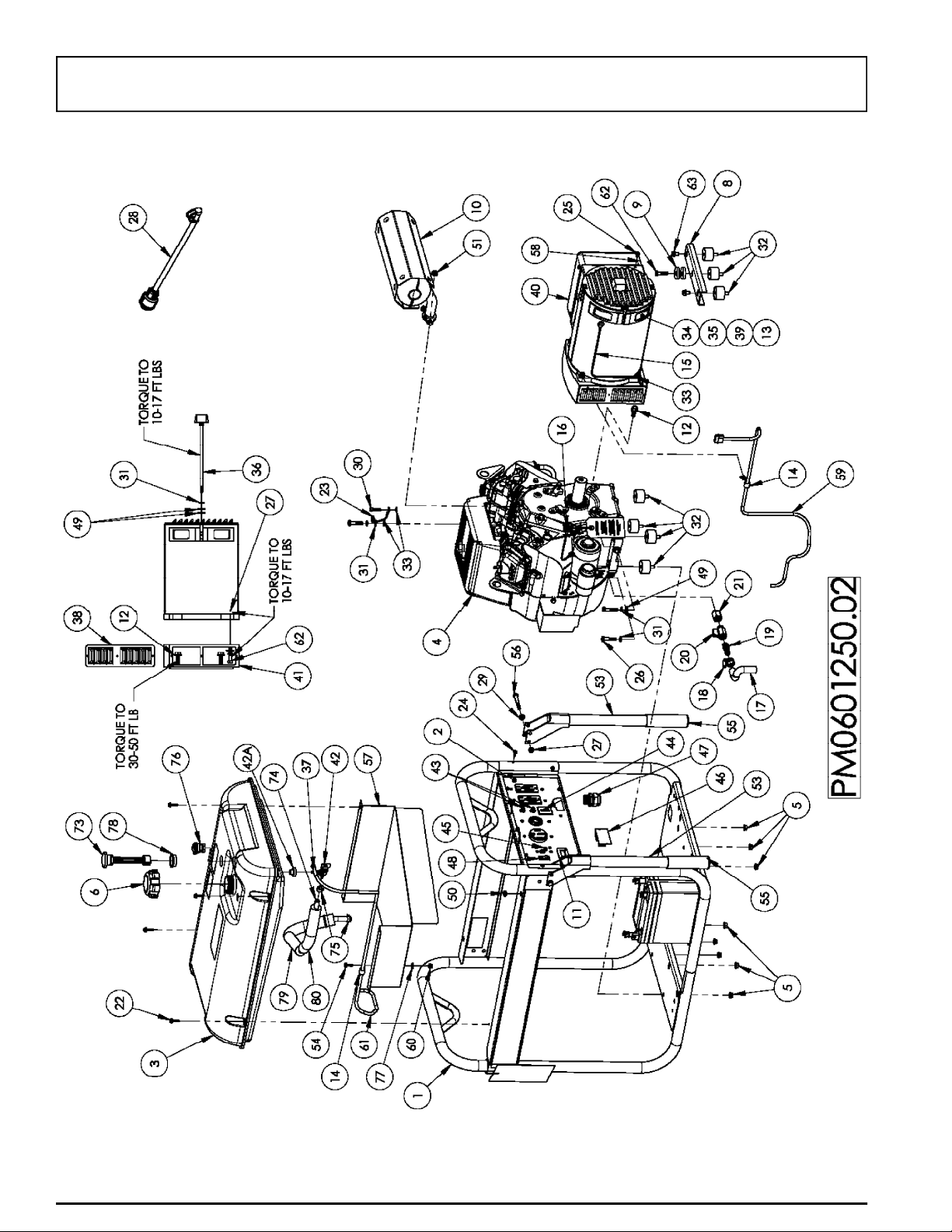
PARTS DRAWING / SCHEMA DES PIÈCES / DIAGRAMA DE PIEZAS
14
Page 2

PARTS LIST / LISTE DES PIÈCES / LISTA DE PIEZAS
REF.PART DESCRIPTION DESCRIPTION DESCRIPCIÓN QTY
NO.NO.
10068928Carrier, assembly, fullEnsemble transport Transportador, conjunto 1
20067517Panel, wired completeTableau compl. câblé Panel, abeado completo 1
3Note C Fuel tank Assembly Ensemble complet du réservoir Conjunto tanque 1
4Note A Engine, 22hp Subaru Moteur Motor 1
50057254Nut, hex flg 5/16-18 Écrous 5/16-18 Tuerca, 5/16-18 8
60065163Cap Fuel Capuchon, réservoir Tapa combustible
d’essence 1
7Note B Washer, flat 7/16 Rondelle plate Arandela plana 2
80056427Assy, Stator bracketPatte de fixation statorSoporte, estator 1
90055620Washer, flat .42 x 1.5Rondelle plate Arandela plana 2
100067206Muffler Silencieux Silenciador 1
110069300Hour meter Horomètre Contador Horario 1
120068937Bolt whz 3/8-16 X 1.00Boulon whz Perno whz 4
130063133Varistor Varistor Varistor 2
140052931Clamp, Vinyl J 1/2” Collier Abrazadera 2
150006253Assy Wire Blk 8ga 17.25Fil Alambre 1
160006254Assy Wire Red 8ga 17.25Fil Alambre 1
17 1130564770 Oil Drain Hose Boyau de vidange d’huileManguera para drenar el
aceite 6”
18Note B Clamp hose worm SAE6Collier SAE6 Abrazadera SAE6 1
190057747Fitting 3/8NPT x 1/2 barbRaccord Adaptador 1
200057746Valve ball 3/8NPT M/FSoupape Válvula 1
210062499Fitting 3/8NPTF 14mm-MRaccord Adaptador 1
220058618Screw, #10 x 1 Vis Tornillo 4
230049224Assembly, ground wireEns. fil de masse tresséConjunto, cable trenzado a tierra 1
240053320Screw HWH #10-14 x .63Vis Tornillo 4
250047864Screw HSW #10-32 x .5Vis Tornillo 1
26Note B Bolt HH 5/16-18 x 1.5Boulon Perno 6
270048736Nut Nyloc 5/16-18 Écrous nyloc Tuerca, nyloc 20
280056680Filler Flootool FunnelEntonnoir Embudo 1
29Note B Washer, flat 5/16 Rondelle plate Arandela plana 18
30Note B Bolt HH 5/16-18 x 1 Boulon Perno 9
31Note B Washer, lock 5/16 Contre-écrou Arandela, de cierre 9
320051094Isolator Sectionneur Aislador 7
33Note B Washer, star ext 5/16Rondelle à dents Arandela, estrella externa 3
34 AMM12000RB0000Y Alternator Alternateur Alternador 1
350062581Diode Diode Diode 2
360062582Bolt, rotor Boulon, rotor Perno, rotor 1
370050859Clamp, Hose Crampon, tuyau Abrazadera, manguera 1
380056629Louvered Side Panel Panneau latéral à persiennes Tablero lateral con rejillas 2
39G079102Capacitor, 35uf 450VCapaciteur Capacitor 2
400062585Generator Head coverCouvercle de la tête de la Cubierta del cabezal del
génératrice generador 1
410056623Adapter, engine Adaptateur pour moteurAdaptador, motor 1
420064729Fuel valve with filter Robinet de carburant avec Válvula combustible con filtro
filtre 1
42A0062673Fuel bushing Bague d’essence Buje de combustible 1
430049071Circuit Protector 20A Protecteur de circuit 20 ampProtector de circuito 20 amp 2
440062838Circuit Protector 30A dualProtecteur de circuit 30 ampProtector de circuito 30 amp 1
450056705Circuit Protector 50A dualProtecteur de circuit 50 ampProtector de circuito 50 amp 1
460062543I/C Module DC Module de commande du Módulo, control en vacío
ralenti 1
470049291Strain Relief Réducteur de tension Protección contra tirones 1
480050298Rocker Switch Interrupteur à bascule Interruptor de balancín. 1
490049352Washer, flat 5/16 W Rondelle plate Arandela plana 8
500066813Grommet, 3/8 ID Oeillet Arandela de cabo 1
510061393Nut, whz 8mm Écrous whz 8mm Tuerca whz 8mm 4
520059392Pin, release Epingle de relâchementAlfileres de la liberación 2
530067471Handle Poignée Manija 2
54Note B Bolt HH 1/4-20 x .75 Boulon Perno 1
15
Page 3

PARTS LIST / LISTE DES PIÈCES / LISTA DE PIEZAS
REF.PARTDESCRIPTION DESCRIPTION DESCRIPCIÓN QTY
NO.NO.
550062495Grip, handle Poignée Empuñadura 2
56Note BBolt HH 5/16-18 x 2.25Boulon Perno 2
570062540Shield, heat
580057183Grommet 7/8 ID Oeillet Arandela de cabo 1
590064639Assy, wire harness Ensemble, d'harnais de fil Conjunto de arreos de alambre 1
60
0040832Nut Nyloc 1/4-20 Écrou nyloc Tuerca, nyloc 1
610068954Fuel hose 4.5mm ID Flexible de carburant Manguera de combustible 1
62Note BBolt HH 5/16-18 x 1.25Boulon Perno 1
630049279Bolt whz 5/16-18 X .50Boulon whz Perno whz 2
640069998Wheel Roue Rueda 2
650056406Wheel bracket Ferrure de la roue Ménsula de la rueda 2
660067477Foot bracket Ferrure de la pied Ménsula de la pie 1
670008433Foot, rubber Pied Pie 2
680056409Strap, foot bracket Sangler, ferrure de la piedCorrea, ménsula de la pie 1
690056444Cap, axle Capuchon Tapa 2
700062510Wheel spacer Bague d’espacement Espaciador de la rueda 2
71Note BBolt HH 5/16-18 x 2.00Boulon Perno 4
720062174Lanyard Lanyard Acollador 2
730067718Fuel gauge Jauge de carburant Indicador de combustible 1
74 1130634480 Fuel hose 1/4 ID Flexible de carburant Manguera de combustible 1
750035857Clamp, Hose Crampon, tuyau Abrazadera, manguera 2
760070391Valve, rollover Soupape Válvula 1
77Note BWasher, flat 1/4 Rondelle plate Arandela plana 1
780068002Grommet 1.20 ID Oeillet Arandela de cabo 1
790057797Foam insulation 12” Isolation 12 po Aislamiento12 pulg 1
800051669Foam insulation 7.25”Isolation 7,25 po Aislamiento7,25 pulg 1
Écran de chaleur Pantalla para el calor 1
Note A:
Pramac America, LLC will not provide engines as replacement parts. Engines are covered through the engine manufacturer's warranty. Consult the accompanying
engine manual or contact our service department for assistance.
Note B:
These are standard parts available at your local hardware store.
Note C:
Contact your nearest Powermate ® Service Center for replacement fuel tanks.
WARNING: To avoid possible personal injury or equipment damage, a registered electrician or an authorized service representative should
perform installation and all service. Under no circumstances should an unqualified person attempt to wire into a utility circuit.
Remarque A:
manuel du moteur inclus ou contacter notre département de service après-vente pour toute assistance.
Remarque B:
Remarque C:
Nota A:
manual adjunto del motor o comuníquese con nuestro departamento de servicio para recibir ayuda al respecto.
Nota B:
Nota C:
Pramac America, LLC ne fournit pas de moteurs dans ses pièces détachées. Les moteurs sont couverts par la garantie du fabricant de moteurs. Consulter le
Ces pièces sont des pièces standard disponibles en quincaillerie.
Pour commander un réservoir de rechange, contacter Centre de service Powermate ® le plus proche.
AVERTISSEMENT: Pour éviter toute blessure personnelle ou dommage à l’équipement, l’installation et tout entretien devralent être effectués par un
électricien qualifié ou un préposé au service autorisé. En aucun cas, une personne non-qualifiée ne devrait essayer de faire le raccord au circuit principal.
Pramac America, LLC no proporcionará los motores como repuestos. Los motores están cubiertos por medio de la garantía del fabricante del motor. Consulte el
Estas son piezas estándar disponibles en su ferretería local.
Para hacer pedidos de tanques, localice el Centro de Servicio de Powermate ®más cercano.
ADVERTENCIA: Para evitar posibles lesiones físcas o daños materiales, es necesario que la instalación y todo el servicio sea realizado por un electricista
matriculado o representatnte de servicio autorizado. Bajo ninguna circunstancia debe permitirse que una persona que no está capacitad trate de
manipular cables dentro del circuito de servicio eléctrico.
16
Page 4

PORTABILITY KIT INSTALLATION
TOOLS REQUIRED: Hammer, 1/2” wrench, ratchet with a 1/2” socket, and wood blocks.
Refer to the drawing for proper alignment of Foot bracket and Wheel brackets.
Refer to the parts list on pages 15 and 16.
Wheel Bracket & Wheel Installation
1. Block up end of generator, about 8” high, opposite the fuel tank cap to install wheels and wheel bracket assy.
2. Add 5/16 washer (item 29) to the 1 3/4” bolts (item 71) and insert bolts/washers through the holes located in the base pan of
the carrier.
3. Place the wheel bracket (item 65) through the bolts and add a 5/16 nyloc nut (item 27) and tighten securely. (On the bottom
side of the pan in-between the holes will be a 1” square brace, the wheel bracket will set on this brace).
4. Add wheel spacer (item 70) to the axle.
5. Slide the wheel (item 64) onto the axle until it is snug against the spacer. The wheel is on correctly if there is approximately a
1/2” gap between the carrier tubing and the side of the wheel. If it is less then 1/2” from the carrier, turn the wheel over and
reinstall. Align the wheels parallel to the carrier tubing and tighten nuts securly. To align correctly, the bolts holding the wheel
bracket may have to be loosened.
6. With a hammer, add the plastic cap (item 69) on end of axle.
7. Repeat above instructions for the remaining wheel.
Foot bracket Installation
1. Block up opposite end of the unit, about 8” high.
2. Add 5/16 washer (item 29) to 1” bolts (item 30) and place through holes in the base pan.
3. Add foot bracket assembly (item 66) to bolts, add 5/16 nyloc nuts (item 27) and tighten securely.
4. Repeat above instructions for the remaining foot bracket assembly.
Locking Handle
1. Attach the lanyards (item 72) to the release
pins (item 73) and carrier as shown in the
illustration.
2. To lock the handle in the extended position,
align the holes in the handle brackets with the
holes in the carrier brackets and insert the
release pins.
1
72
52
2
4
English
 Loading...