

Page 1
Page 2

Installation Instructions and
Instructions for Continued Airworthiness
Kit: PFS-13204, PFS-13205
TABLE OF CONTENTS
1.0 INTRODUCTION....................................................................................................................................................... 3
1.1 General 3
1.2 Upgrading 3
2.0 KIT CONTENTS......................................................................................................................................................... 5
2.1 Classic Tailpipes 5
2.2 Short Stack Tailpipes 6
3.0 PREPARATION.......................................................................................................................................................... 7
4.0 INSTALLATION OF THE PFS EXHAUST SYSTEM.............................................................................................. 7
4.1 Installing Collector Box assembly and Exhaust pipes: 7
4.2 Classic Tailpipe Installation 8
4.3 Short Stack Tailpipe Installation 10
INSPECTION AND PAPERWORK......................................................................................................................... 11
5.0
6.0 INSTRUCTIONS FOR CONTINUED AIRWORTH INE SS .................................................................................... 11
6.1 Basic Operation 11
6.2 Airworthiness Limitations 11
6.3 Troubleshooting 13
6.4 Maximizing Service Life 14
6.5 Removal 14
6.6 Inspection 14
DETAIL A ............................................................................................................................................................................. 16
DETAIL B.............................................................................................................................................................................. 17
DETAIL C.............................................................................................................................................................................. 18
DETAIL D ............................................................................................................................................................................. 19
INSTALLATION OVERVIEW - CLASSIC......................................................................................................................... 20
PASSENGER SIDE VIEW - CLASSIC................................................................................................................................21
PILOT SIDE VIEW - CLASSIC............................................................................................................................................ 22
REAR VIEW - CLASSIC...................................................................................................................................................... 23
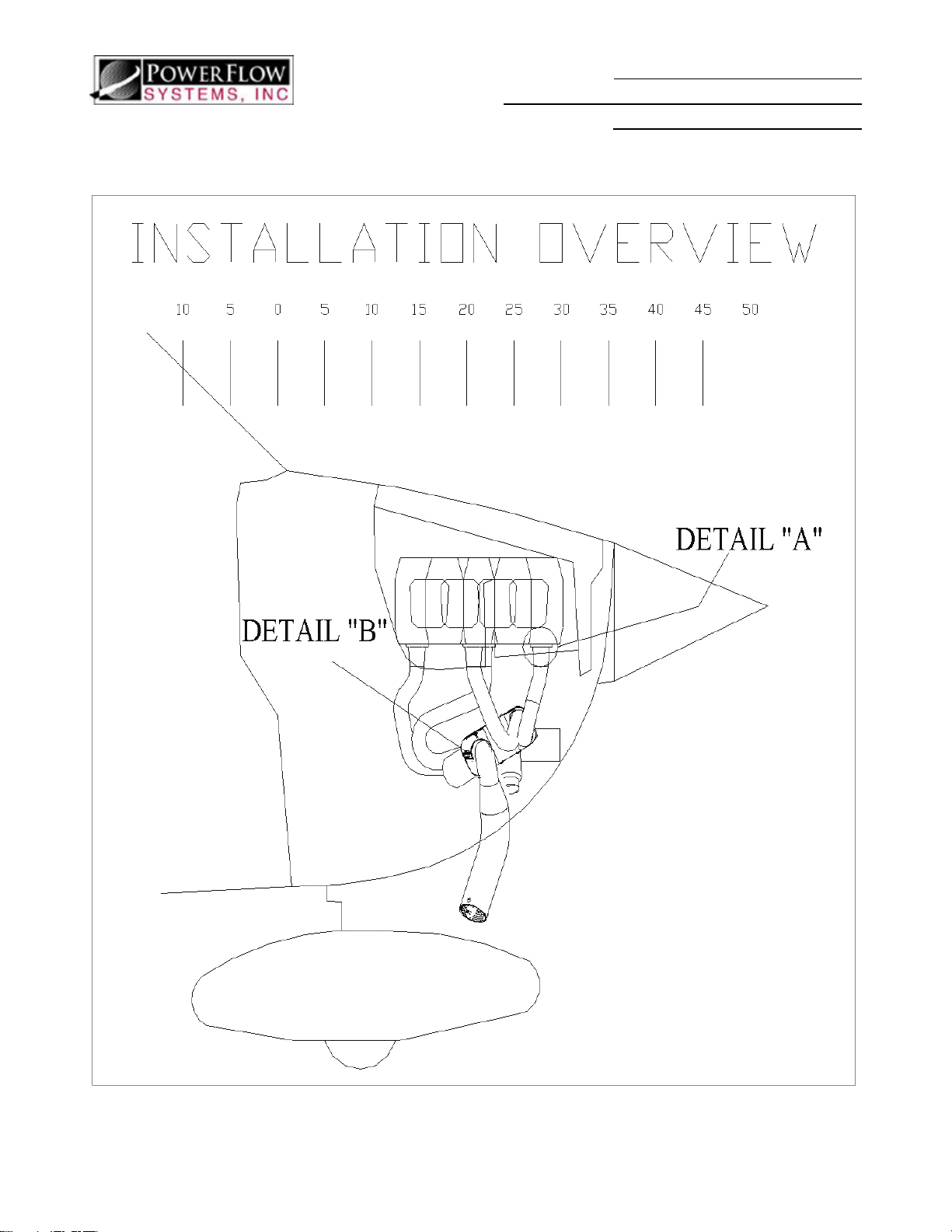
INSTALLATION OVERVIEW – SHORT STACK.............................................................................................................. 24
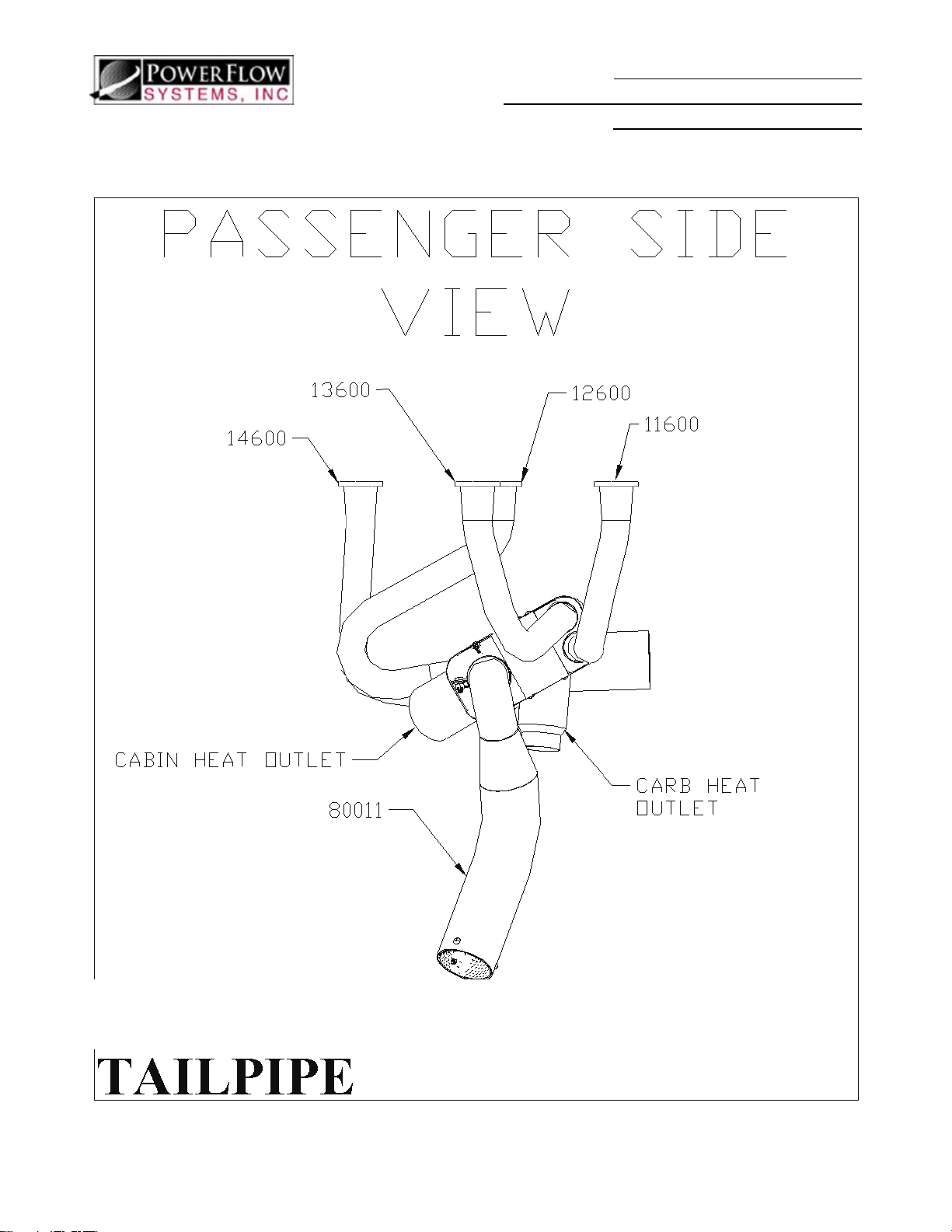
PASSENGER SIDE VIEW – SHORT STACK..................................................................................................................... 25
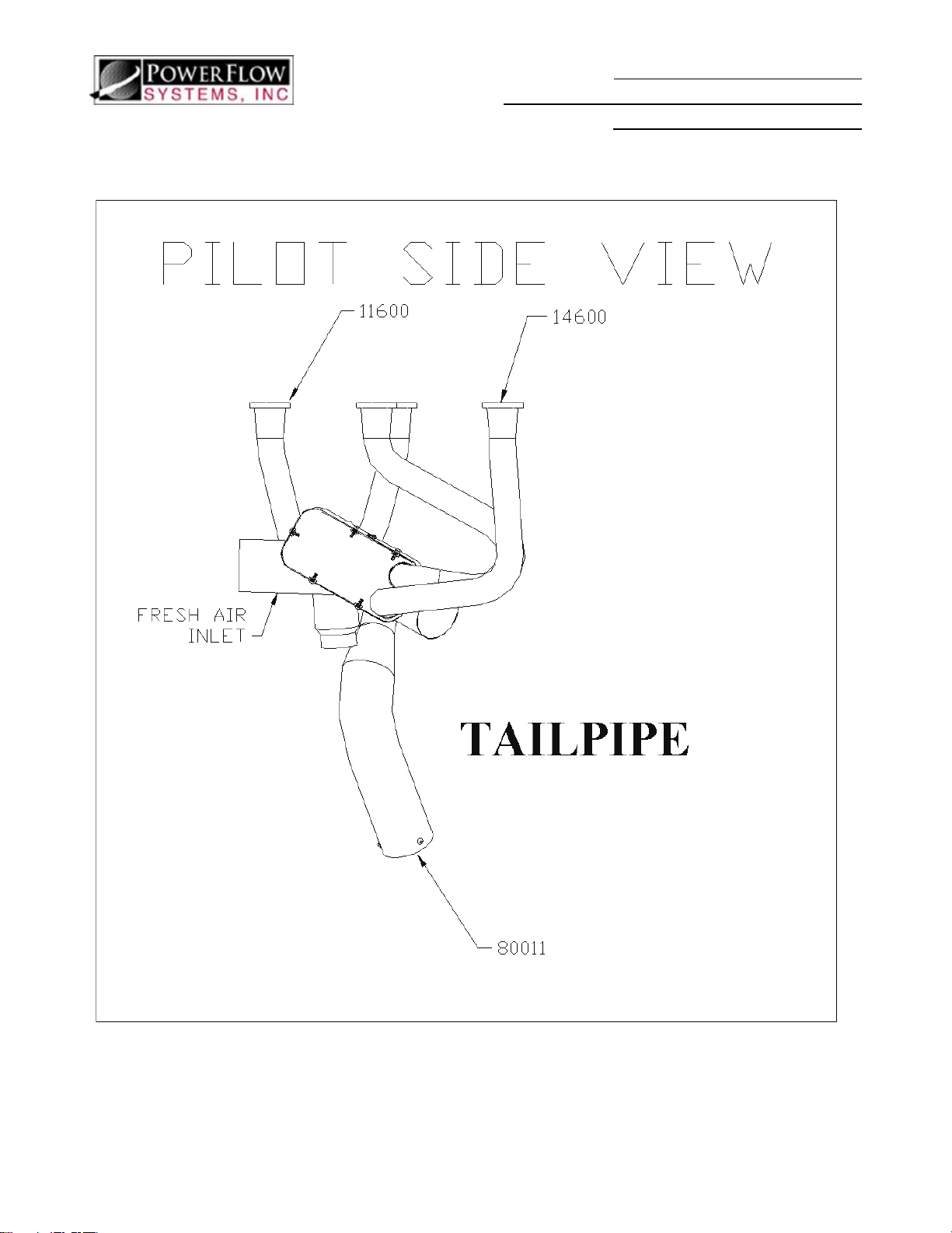
PILOT SIDE VIEW – SHORT STACK................................................................................................................................26
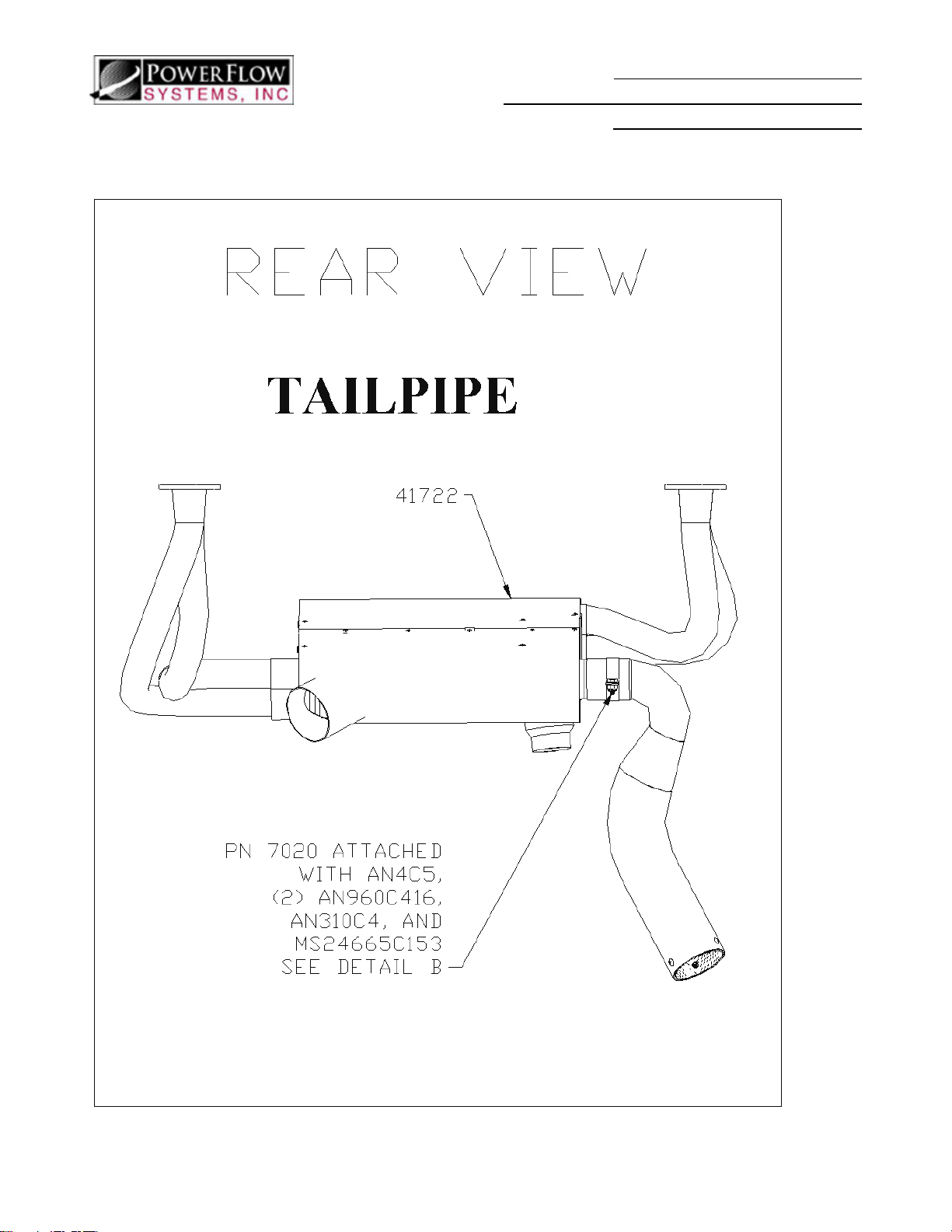
REAR VIEW – SHORT STACK........................................................................................................................................... 27
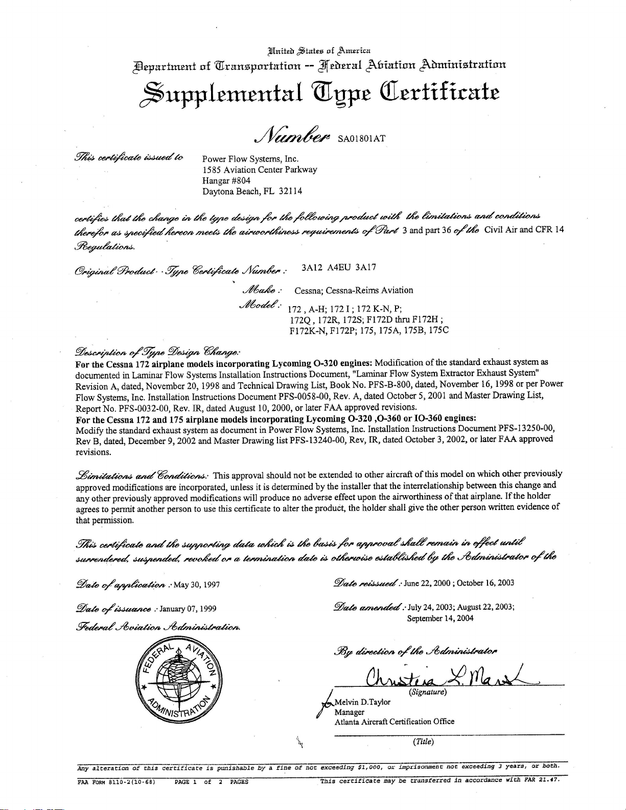
STC ................................................................................................................................................................................... 28
PFS-13250-00 Rev G Page 2 of 28 July 23, 2009
Page 3

1.0 INTRODUCTION
1.1 General
• PFS is the abbreviation for Power Flow Systems.
• Please read these instructions and the instructions for continued airworthiness comp letely
before starting installation. Please call us at 386-253-8833 during normal business hours if
you have any questions regarding the installation of this kit.
• The Power Flow Systems Exhaust has been designed and FAA certified to be installed in
accordance with these instructions. Any modification to the exhaust system or its
components, or any deviation from these instructions without express written permission
from Power Flow Systems, Inc. invalidates the design and the FAA approval. Any such
modifications or deviations will also void the exhaust system warranty.
• If your cowling has been modified at all to be different than when it was originally built,
please ensure our modification will be compatible before installation or flying.
Installation Instructions and
Instructions for Continued Airworthiness
Kit: PFS-13204, PFS-13205
• Customers with classic tailpipes please note: Carbon Monoxide testing was performed
with the muffler positioned as described in these instructions. Repositioning the muffler
and/or support rod may cause carbon monoxide to enter the aircraft cabin.
1.2 Upgrading
• The installer should complete FAA 337 paperwork (or their international equivalent) for
upgrade installations. All upgrades are approved under the original STC number. The
STC has been provided as the last page of these instructions.
• The new parts will be warranteed for 1 year or 500 tach hours, following their installation,
whichever comes first. Parts that are reused will be subject to their original warranty and
will be covered based on the time of their initial installation.
• If you require a new muffler (Ceramic Coated Mufflers are now available) or muffler
insert (P/N 8016), please contact Power Flow Systems, Inc. for details.
1.2.1 Upgrading from “Classic System”
• If you are upgrading from a PFS-13201, PFS-13202, or PFS-13203 exhaust system
you will need to reuse your existing support rod, muffler, and muffler clamp (unless
upgraded to Short Stack tailpipe at the same time). New hardware has been
provided.
1.2.2 Upgrading to “Short Stack” Tailpipe
• If your exhaust system has already been installed, and you are just upgrading to the
Short Stack tailpipe, skip to Section 4.3 of the installation instructions. Before you
begin, remove the support rod (PN 90020) from the lower right engine lord mount
(be sure to reinstall the bolt and torque to the aircraft or engine manufacturer’s
recommended value). Also, remove the intermediate tube (PN 78102) from the 4-1
outlet. If a hole was cut in your cowling for the support rod to pass through, you
PFS-13250-00 Rev G Page 3 of 28 July 23, 2009
Page 4

Installation Instructions and
Instructions for Continued Airworthiness
Kit: PFS-13204, PFS-13205
may wish to patch the hole. This should be done in accordance with the latest
revision of AC43.13.
1.2.3 Upgrading from a Lycoming O-320 to O-360
• If upgrading your aircraft from an O-320 engine to an O-360 engine, you will need
to change your number 2 and number 4 headers.
• If your O-360 airbox requires a 3.0” carb heat adapter, contact Power Flow Systems,
Inc. for a P/N 6583 adapter.
• If your new engine uses a 2.5” carb heat connection and your previous engine used a
2.0” carb heat connection, cut off the reducer portion of the carb heat outlet on the
heat shroud.
PFS-13250-00 Rev G Page 4 of 28 July 23, 2009
Page 5

Installation Instructions and
Instructions for Continued Airworthiness
Kit: PFS-13204, PFS-13205
2.0 KIT CONTENTS
2.1 Classic Tailpipes
Quantity Part Description Part Number
1 #1 Header 11600
1 #2 Header 12600*
1 #3 Header 13600
1 #4 Header 14600*
4 No-blow Header Gasket 77611
8 Exhaust Nut SL-STD-1410
8 Lock Washer MS35333-41
8 Plain Washer AN960-516
1 Shrouded Collector Assembly 41722**
1 Exhaust Extension Assembly 78102
2 Exhaust Clamp (2” with pin) 7020
3 Bolt AN4C5A
3 Castle Nut AN310C4
3 Cotter Pin MS24665-153
8 Flat Washer AN960C416
1 Adel Clamp size 6 MS21919WH6
1 Adel Clamp size 12 MS21919WH12
1 Locknut MS21044C3
1 Bolt MS51958-63
2 Flat Washer AN960C10
1 Muffler Assembly 80010
1 Support Rod 90020
1 Muffler Clamp (3 1/2” without pin) 8030
42” Scat Tubing SCAT-12
Equivalent hardware may be supplied.
*Aircraft with O320 Engines will receive 12600-1 and 14600-1 headers.
**Cessna 172R and 172S will use P/N 41723.
PFS-13250-00 Rev G Page 5 of 28 July 23, 2009
Page 6

Installation Instructions and
Instructions for Continued Airworthiness
Kit: PFS-13204, PFS-13205
2.2 Short Stack Tailpipes
Quantity Part Description Part Number
1 #1 Header 11600
1 #2 Header 12600*
1 #3 Header 13600
1 #4 Header 14600*
4 No-blow Header Gasket 77611
8 Exhaust Nut SL-STD-1410
8 Lock Washer MS35333-41
8 Plain Washer AN960-516
1 Shrouded Collector Assembly 41722**
1 Short Stack Tailpipe Assembly 80011
1 Exhaust Clamp (2” with pin) 7020
1 Drilled Bolt AN4C5
1 Castle Nut AN310C4
1 Cotter Pin MS24665-153
2 Flat Washer AN960C416
42” Scat Tubing SCAT-12
Equivalent hardware may be supplied.
*Aircraft with O320 Engines will receive 12600-1 and 14600-1 headers.
**Cessna 172R and 172S will use P/N 41723.
PFS-13250-00 Rev G Page 6 of 28 July 23, 2009
Page 7

Installation Instructions and
Instructions for Continued Airworthiness
Kit: PFS-13204, PFS-13205
3.0 PREPARATION
Verify that all contents listed on page 4 of this instruction set are included in your kit. Read all
instructions before attempting installation, to become familiar with the procedure. If you have any
questions regarding the installation, please call (386) 253-8833 before
3.1 Remove lower cowl components in accordance with the latest approved revision of the
Aircraft Service Manual.
3.2 Disconnect flexible ducts from muffler assembly.
3.3 Cover heat carb inlet to prevent debris from entering the carburetor (if applicable).
3.4 Remove EGT probe(s), if installed.
3.5 Remove nuts attaching exhaust pipes to exhaust studs.
3.6 Remove exhaust pipes and exhaust gaskets.
3.7 The PFS Carburetor heat outlet is designed to accept 2 common sizes of SCAT hose. If your
hose is 2.5” in diameter, cut off and de-burr the reducer portion of the adapter. If your aircraft
uses a 3” carb heat connection, install PN 6583 (reducer) to step your 3” SCAT hose down to
2” for attachment to the carb heat shroud. Be sure that the SCAT tube routing does not
interfere with any moving parts. PN 6583 can be installed with two band clamps. (Not
applicable to fuel injected engines).
attempting installation.
4.0 INSTALLATION OF THE PFS EXHAUST SYSTEM
4.1 Installing Collector Box assembly and Exhaust pipes:
Both collector styles, 41722 and 41723, are installed in the same manner.
4.1.1 Insert the number 1 and number 3 exhaust header pipes into the collector assembly
as per the numbering on the collector and headers. Be sure to use the alignment
marks. A minimum of 1 ½ ” penetration is required for proper operation. Put new
gaskets into position on each cylinder. It is suggested that you keep them in place
temporarily with either a loop of safety wire or a large cotter pin. Lift and hold the
assembly into position; be sure the shroud inlet tube passes cleanly through the front
baffle. Start a nut on each header to hold the entire assembly in place. See Detail
“A”, Passenger and Pilot Side Views.
4.1.2 Insert the number 2 and number 4 header pipes into the collector assembly as per
the numbering on the collector and headers. Be sure to use the alignment marks. A
minimum of 1 1/2” penetration is required for proper operation. Be sure to use the
new gaskets provided. If the system is being re-installed and alignment marks are
not visible, set the collector box to a 30 degree up-angle with respect to the engine
centerline and make sure all headers are inserted equally (about 1.6 inches).
4.1.3 Install a washer, a lock washer and a nut on each stud (there are 8 sets of these). If
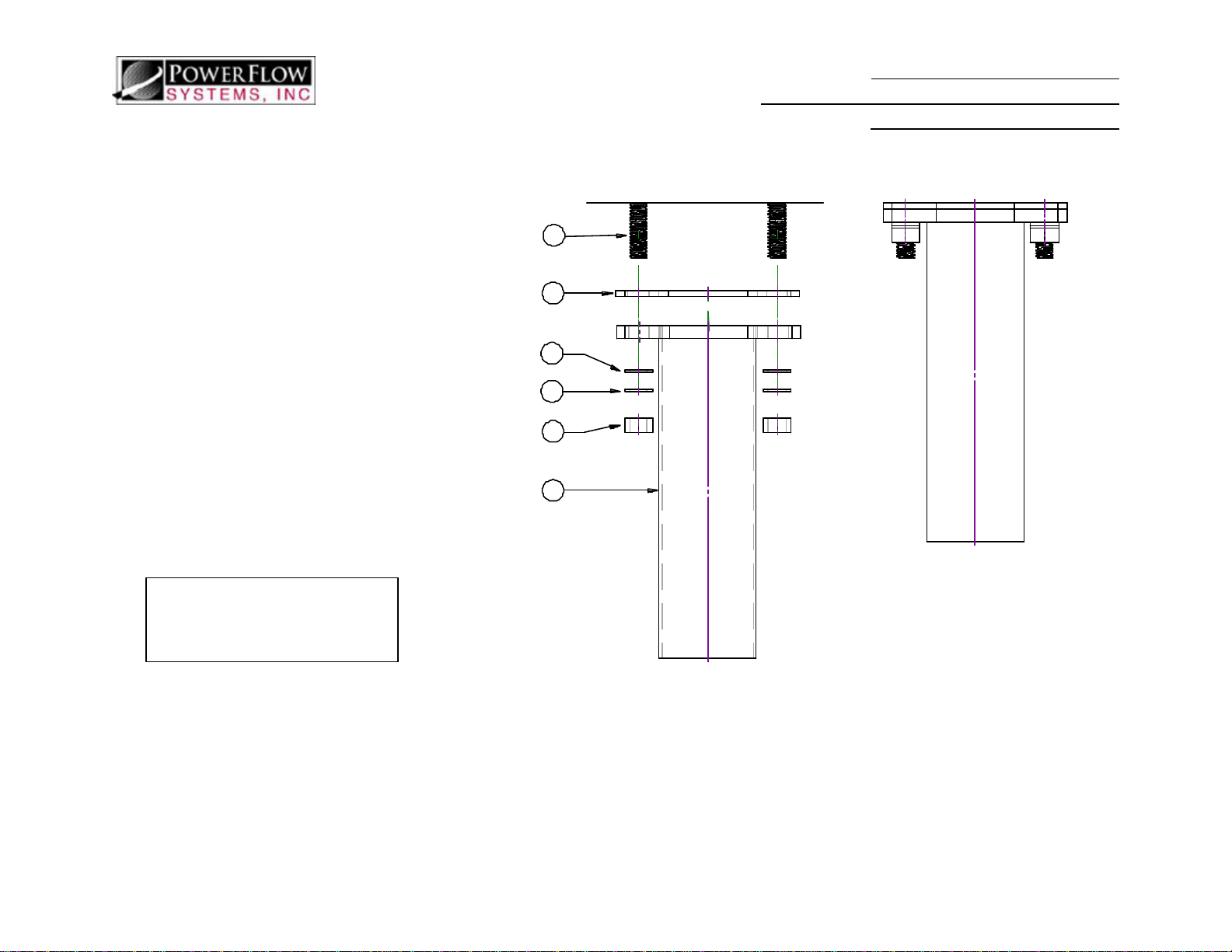
utilized, remove the loops of safety wire or cotter pins. Torque I.A.W. the latest
revision of the aircraft or engine service manual. See Detail “A” and Pilot Side
View.
4.1.4 Install EGT Probes (If Applicable) I.A.W. the manufacturer’s recommendations. All probes should be the same distance from the port, typically 2-4 inches.
4.1.5 Install flexible tubing to shroud connections. The cabin heat outlet is on the aftpilot side of the shroud (PN 41722 and PN 41723). PN 41722 has a carb heat outlet
on the passenger side of the shroud. PN 41723 does not have a carb heat outlet.
PFS-13250-00 Rev G Page 7 of 28 July 23, 2009
Page 8

4.2 Classic Tailpipe Installation
If your exhaust has a Short Stack Tailpipe, Please Skip to Section 4.3.
Installing Support Rod P/N 90020:
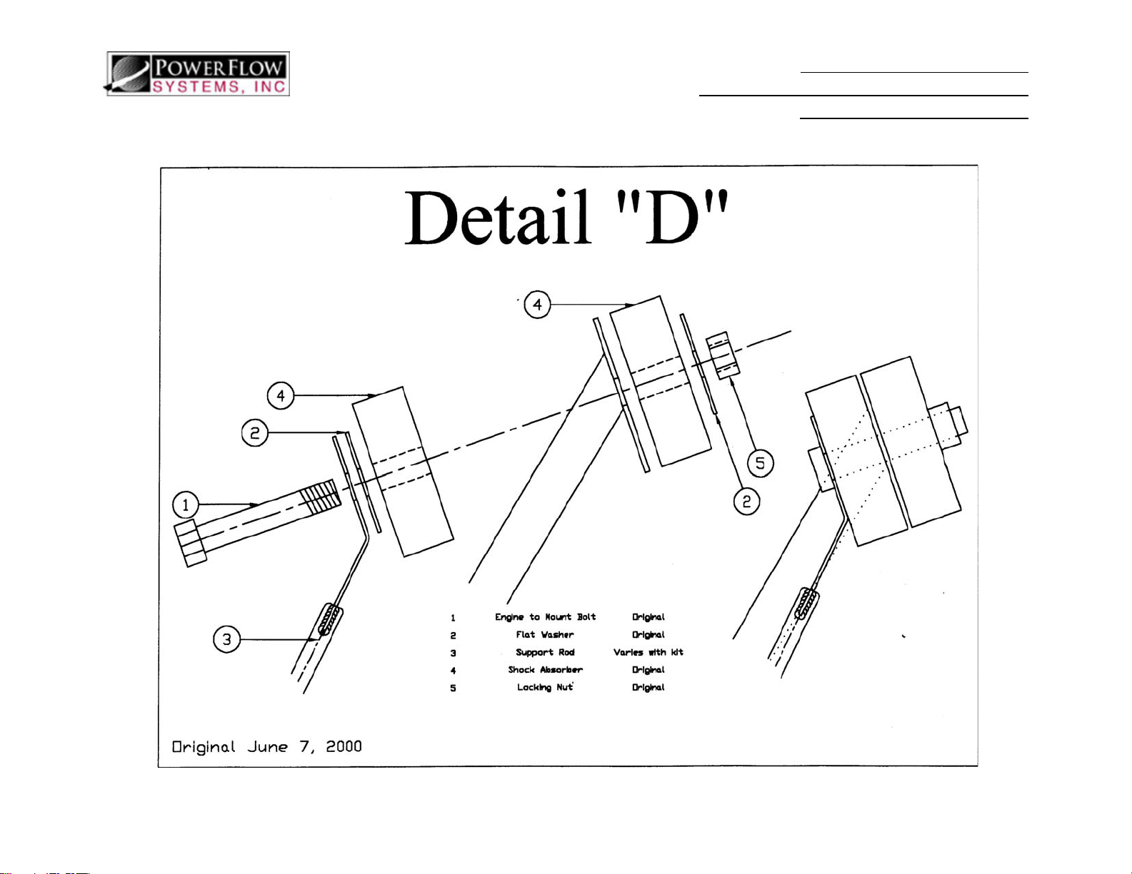
4.2.1 Examine the right lower engine mount bolt and nut. If you have one to two threads showing at the nut, it may be necessary to install the next dash number longer AN7 bolt after installing our support rod adapter. See Detail “D”.
4.2.2 Loosen and remove the lower right engine Lord mount bolt. Our support rod adapter
(the teardrop shaped piece of metal welded to the support rod) goes under the bolt
head, on top of the existing large area washer. This large area washer may be
omitted if the bolt is too short. See Detail “D”. Ensure that the rod clears all engine
compartment parts, and will exit the cowl well forward of the firewall, slightly
outboard of the engine lord mount and directly above the muffler assembly (The
muffler, PN 80010, can be temporarily installed onto exhaust extension PN 78102 to
check this alignment). Also make sure that the end of the support rod will clear the
bottom of the aircraft cowl.
4.2.3 Tighten the Lord mount bolt, but DO NOT TORQUE TO VALUE YET. You will fully torque the mount once the position and adjustment of the support rod is complete.
4.2.4 Using the Adel clamps provided, secure the support rod to the engine mount. MODIFYING THIS SUPPORT ROD OR FABRICATING ADDITIONAL SUPPORT MAY CAUSE PARTS TO FAIL AND WILL VOID YOUR WARRANTY.
4.2.5 Place the included template of the lower cowling according to the instructions on
the template. Generally, cowlings built prior to 1972 do not require any hole
cutting.
4.2.6 Cut out the hole as indicated. If the template doesn’t fit, or if you have any
questions regarding this cut, please call for assistance before cutting hole.
4.2.7 Slide the exhaust extension PN: 78102 all the way onto the end of the 4-to-1 collector. DO NOT drill for clamp installation, yet.
4.2.8 Position the lower cowl onto the airplane. Attach the cowl with enough screws to
ensure the proper angle of the cowl. The support rod should pass cleanly through
the hole drilled through the cowl, and the exhaust extension should pass through the
middle of the stock exhaust outlet. It may be necessary to temporarily attach the
upper cowl to attain the proper cowling angle.
4.2.9 Slide the muffler assembly, P/N 80010, over the exhaust extension outlet. It should
be pushed up as far it can go, oriented straight back. The support rod should be
contacting the muffler. You may have to make minor adjustments in alignment and
rotation of both the muffler assembly and the exhaust extension assembly. Any
deviation in muffler and/or support rod alignment may cause carbon monoxide to
enter the aircraft cabin. The muffler must be pointed down and away from the
aircraft—not parallel to the fuselage—in order to ensure that no exhaust gases enter
the aircraft cabin.
Installation Instructions and
Instructions for Continued Airworthiness
Kit: PFS-13204, PFS-13205
PFS-13250-00 Rev G Page 8 of 28 July 23, 2009
Page 9
Installation Instructions and
Instructions for Continued Airworthiness
Kit: PFS-13204, PFS-13205
4.2.10 Position the large clamp, P/N 8030, around the muffler so that it will attach to the support rod.
4.2.11 If a nose pant is installed, turn the nose gear fully to the left and ensure that the
muffler assembly does NOT strike the pant. If needed, rotate the muffler outward.
The support rod can be carefully bent to assist in assuring that the support rod and
muffler clamp stay in alignment. If the end tab does not align flat against the clamp,
twist the tab with pliers until it lays flat.
Warning: Fuel strainer outlet must be redirected so that it does not spray fuel on tailpipe during fuel
strainer drain operation.
Installing Exhaust Extension and Muffler
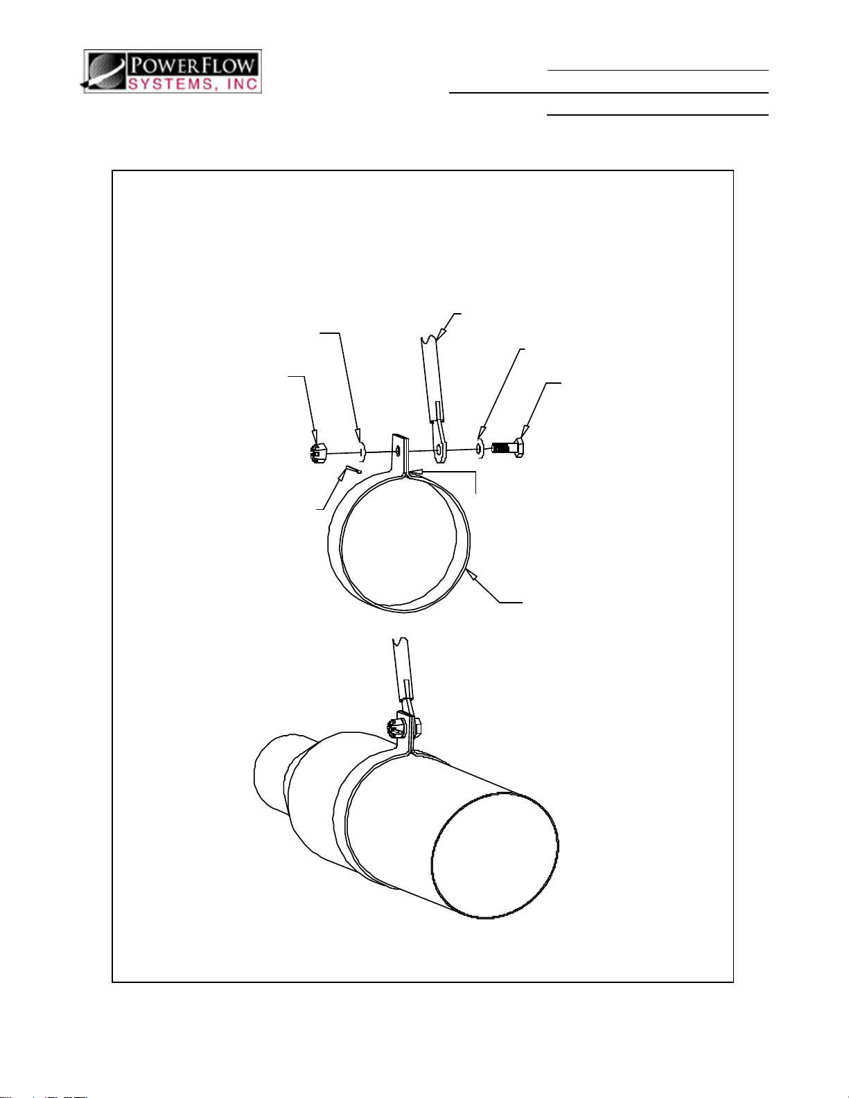
4.2.12 Install the large clamp (without the pin) so that the holes will align with the hole in the support rod. See Detail “C”.
4.2.13 Drill a 0.25” hole through the pilot hole in the muffler through the exhaust extension.
4.2.14 Remove the muffler.
4.2.15 Remove the lower cowl.
4.2.16 Reattach the muffler and temporarily install the large clamp.
4.2.17 Drill a 0.25” hole through the flared end of the exhaust extension, about one inch
from the end of the flare. Drill through the exhaust extension and the 4 to 1
collector. Be sure to de-burr all the holes or later removal of muffler components
will be difficult.
4.2.18 Clamp the exhaust extension to the 4 to 1 using one of the provided 2” clamps (PN
7020). See Detail “B”. The pin should insert with minimal force. If any binding
exists, the hole may need further reaming.
4.2.19 Remove the muffler and re-install the lower cowl. Install the muffler assembly and clamp to the exhaust extension with the other 2” clamp. See Detail “B”. Again, if the pin is a tight fit, further reaming of the hole may be necessary.
4.2.20 Clamp the muffler assembly to the support rod with the provided 3.5” clamp. See Detail “C”.
4.2.21 Now that all of the support mechanism for the muffler is correct, tighten the engine
mount to manufacturer’s specified torque. Be sure that the support rod doesn’t
rotate when tightening. Make sure that you have at least one to two threads showing
through the nut on the engine mount. It may be necessary to install a longer bolt.
4.2.22 Depending on your aircraft, it may be necessary to slightly increase the size of the
tailpipe opening in the cowling. Some aircraft with engine conversions may require
more clearance on the outboard side of the tailpipe. If this is necessary, a doubler
may be installed to cover some of the excessive opening on the inboard side of the
tailpipe.
Any deviation in muffler and/or support rod alignment may cause carbon monoxide to enter the
aircraft cabin. The muffler must be pointed down and away from the aircraft—not parallel to
the fuselage—in order to ensure that no exhaust gases enter the aircraft cabin.
PFS-13250-00 Rev G Page 9 of 28 July 23, 2009
Page 10

4.3 Short Stack Tailpipe Installation
If your exhaust has a Classic Tailpipe, Skip to Section 5.0
4.3.1 Slide the tailpipe, PN 80011 all the way onto the end of the 4-to-1 collector. DO NOT drill for clamp installation, yet.
4.3.2 Position the lower cowl onto the airplane. Attach the cowl with enough screws to
ensure the proper angle of the cowl (please note that the lower cowl may “sag”
without the top cowl installed, for best results, we recommend installing the top
cowl). The tailpipe should pass cleanly through the exhaust pipe opening. The pipe
should be angled slightly outboard and slightly aft, just like the stock exhaust
tailpipe.
4.3.3 Depending on your aircraft, it may be necessary to slightly increase the size of the
tailpipe opening in the cowling. Some aircraft with engine conversions may require
more clearance on the outboard side of the tailpipe. If this is necessary, a doubler
may be installed to cover some of the excessive opening on the inboard side of the
tailpipe.
4.3.4 Mark the junction of the slip joint to indicate the proper rotation angle.
4.3.5 Remove the cowling.
4.3.6 Drill a 0.25” hole through the flared end of the tailpipe, about one inch from the end of the flare.
4.3.7 Install clamp PN 7020 using provided hardware. See Detail B. The pin should insert with no more than moderate hand pressure. If binding exists the hole may need further reaming.
Installation Instructions and
Instructions for Continued Airworthiness
Kit: PFS-13204, PFS-13205
PFS-13250-00 Rev G Page 10 of 28 July 23, 2009
Page 11

Installation Instructions and
Instructions for Continued Airworthiness
Kit: PFS-13204, PFS-13205
5.0 INSPECTION AND PAPERWORK
5.1 Be sure that the final installation allows a minimum of 2” clearance between unshielded
exhaust tubes and fuel and oil lines or battery cables. Verify that fuel, oil, and electrical lines
are properly supported. Nylon, plastic, or rubber ties can melt and cause fuel, oil, or electrical
lines to fall onto exhaust system components.
5.2 After installing the cowling and performing run-up, inspect the tailpipe and cowling for rubbing
or chafing. The hole that the tailpipe passes through may need to be enlarged based on the
amount of motion caused by engine start and shutdown. The motion of the tailpipe will be
greatest during engine start and shutdown. Excessive motion could be an indication of worn
engine Lord mounts.
5.3 Install the placard (enclosed) in clear view of the pilot that reads:
“The Power Flow Systems, Inc. tuned exhaust system may cause the aircraft to burn more fuel at high
power settings when running a rich mixture. It is the Pilot’s responsibility to determine what, if any,
change in fuel flow exists and to plan accordingly.”
5.4 Make appropriate entries in the logbook and on FAA Form 337. This modification is
considered a major airframe change. The STC is located at the back of this instruction set for
easy removal.
5.5 Typical Weight and Balance Information:
• The original Cessna Exhaust System weighs approximately 16.5 lbs at station –26.0.
• The Power Flow Systems, Inc. tuned exhaust system with the classic tailpipe weighs
22.75 lbs at station –21.0.
• The Power Flow Systems, Inc. tuned exhaust system with the short stack tailpipe
weighs 19.0 lbs at station –24.1.
6.0 INSTRUCTIONS FOR CONTINUED AIRWORTHINESS
It is the responsibility of the aircraft owner/technician to ensure that the most recent
revision of these instructions is followed. The most recent revision of this report can
obtained by calling Power Flow Systems, Inc. at (386) 253-8833 or online at
www.powerflowsystems.com
6.1 Basic Operation
Basic operation of the airplane remains the same. The pilot must watch to ensure that
redline of the RPM is not exceeded.
6.2 Airworthiness Limitations
The Airworthiness Limitations section is FAA approved and specifies maintenance required under
§§43.16 and 91.403 of the Federal Aviation Regulations unless an alternative program has been FAA
approved.
6.2.1 Mandatory Replacement Time – None. Any collector assembly that is damaged
and/or fails the pressure test described below must be rebuilt or replaced with new.
PFS-13250-00 Rev G Page 11 of 28 July 23, 2009
Page 12
Installation Instructions and
Instructions for Continued Airworthiness
Kit: PFS-13204, PFS-13205
6.2.2 Structural Inspection Interval – At 100 hour or Annual intervals, depending on the
service regime of the aircraft. WARNING: Carbon Monoxide gas present in
exhaust gases can lead to pilot incapacitation and/or death. A damaged
exhaust system has the potential to allow Carbon Monoxide into the aircraft
cabin. To prevent such an occurrence, it is imperative that the exhaust system
is inspected using the intervals and procedures described in this report. It is
recommended that in-cabin carbon monoxide levels be measured periodically.
Concentrations of greater than 50ppm will require immediate exhaust system
repair, rebuild, or replacement.
6.2.3 All slip joints must be disassembled and lubricated with a high-temperature anti-
seize compound at 500hr or Annual intervals (whichever comes first). While
disassembled, inspect for wear or galling. This should be performed more
frequently if headers seize between inspections.
6.2.4 Structural Inspection Procedure – See Section 6.6 Below.
PFS-13250-00 Rev G Page 12 of 28 July 23, 2009
Page 13
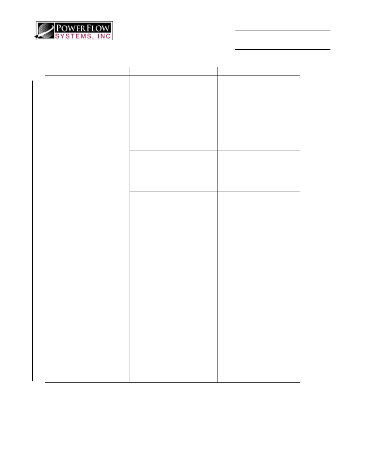
6.3 Troubleshooting
Problem Possible Cause Solution
Exhaust smell or carbon
monoxide in cockpit
Excessive vibration
Excessive noise Muffler insert damaged or
Staining at or near slip
joints.
Exhaust Leak, opening in
firewall or fuselage
Tailpipe or support rod
contacting cowling
Collector not centered on
header pipes
Broken Clamps Replace Broken Clamps
Propeller not properly
balanced
Worn Engine Mounts Inspect Engine mounts
missing
Exhaust Leak or Anti-Seize
stain.
Installation Instructions and
Instructions for Continued Airworthiness
Kit: PFS-13204, PFS-13205
Immediately inspect
exhaust system and
airframe for leaks, do not
return to service until
problem is resolved.
Check for wear marks on
the engine cowling,
reposition tailpipe or trim
opening as necessary.
Reposition collector -ensure minimum of 1 1/2”
penetration per header
into central collector
system
Have propeller
dynamically balanced to
at or below 0.2 ips.
and replace if necessary.
Verify that mounts are
shimmed in accordance
with the Cessna Service
Manual.
Contact PFS, Inc. for new
muffler insert kit, PN
PFS-8016.
Anti-Seize will creep
from slip joints and
appear as a stain, this is
not a problem. Exhaust
leaks from slip joints are
extremely rare, but if
stains are determined to
be from exhaust, the slip
joints should be reworked
for better fit.
PFS-13250-00 Rev G Page 13 of 28 July 23, 2009
Page 14

Installation Instructions and
Instructions for Continued Airworthiness
Kit: PFS-13204, PFS-13205
6.4 Maximizing Service Life
To get the maximum possible service life from your Power Flow Systems Tuned Exhaust,
follow the following steps.
6.4.1 Dynamically balance your propeller to below 0.2 ips (inches per second) every 4
years or 500 hours (whichever occurs first).
6.4.2 Dynamically balance your propeller to below 0.2 ips after modifying, overhauling,
dressing, or replacing any rotating component on the engine or propeller.
6.4.3 Keep slip joints lubricated with a high temperature anti-seize.
6.4.4 Maintain even engine compressions above 70/80 psi.
6.4.5 Keep magnetos in good working order and ensure that mag drops are even and less
than the maximum recommended by the aircraft manufacture.
PLEASE NOTE THAT FAILURE TO COMPLY WITH ONE OR MORE OF THESE
STEPS MAY IMPACT THE PRODUCT WARRANTY. PLEASE CONSULT YOUR
WARRANTY DOCUMENTATION FOR FURTHER DETAILS.
6.5 Removal
6.5.1 Disconnect muffler support rod P/N 90020 from muffler clamp P/N 8030. (Classic
tailpipes only)
6.5.2 Disconnect exhaust clamp P/N 7020 and remove muffler assembly P/N 80010 from
exhaust extension P/N 78102. (Classic tailpipes only)
6.5.3 Remove lower cowl IAW the latest FAA approved revision of the Aircraft Service
Manual.
6.5.4 Disconnect flexible ducts from collector assembly.
6.5.5 Mark each of the header pipes with their respective cylinder number with a felt
tipped pen or marker. Also mark the insertion depth and rotation angle of the
header slip joints. DO NOT MARK EXHAUST PIPES WITH A PENCIL OR
ANY OTHER GRAPHITE OR CARBON BASED MARKING DEVICE.
6.5.6 Remove EGT probes if installed.
6.5.7 Remove exhaust pipes from cylinders 2 and 4 and separate them from the collector
assembly.
6.5.8 Remove the collector assembly by pulling out from the 1 and 3 cylinder side.
6.5.9 Remove the 1 & 3 headers.
6.5.10 Remove the engine mount bolt and support rod if necessary (classic tailpipe only).
6.6 Inspection
The exhaust system must be thoroughly inspected, especially within the heat exchanger
section. A detailed inspection of the exhaust system must be performed in accordance with
the latest revision of the Aircraft Service Manual at either 100 hour or annual intervals.
All components displaying cracking or general deterioration must be replaced with new parts
or repaired in accordance with AC 43.13 or the latest approved revision.
PFS-13250-00 Rev G Page 14 of 28 July 23, 2009
Page 15

Installation Instructions and
Instructions for Continued Airworthiness
Kit: PFS-13204, PFS-13205
6.6.1 Remove exhaust in accordance with paragraphs 6.5.1 through 6.5.9 above.
6.6.2 Loosen and remove heat shroud so that all surfaces of the exhaust system are
visible.
6.6.3 Check for holes, cracks, and burned spots. Especially check areas adjacent to welds.
Look for exhaust gas deposits in surrounding areas. This may indicate an exhaust
leak.
6.6.4 Inspect the baffling in the tailpipe. If the baffling is missing or deteriorated, it will
require replacement. Any deformation of the round perforated tube within the
classic tailpipe indicates that the insert must be replaced. New muffler and baffling
inserts for both tailpipe styles are available from Power Flow Systems, Inc.
6.6.5 Inspect the ball joint for freedom of movement (classic tailpipes only). A seized
ball joint may cause other components to crack. If penetrating lube won’t free a
seized ball joint, please contact Power Flow Systems, Inc. for a replacement.
6.6.6 Inspect screen covering carb heat outlet. Screens must be secure with no risk of
material breaking off.
6.6.7 Inspect pins on clamps. Pins should not indicate excessive wear or cutting. If worn
or cut contact Power Flow Systems, Inc. for replacement.
6.6.8 Inspect holes that pins are inserted in for elongation. If elongated contact Power
Flow Systems, Inc. for a replacement.
6.6.9 All slip joints must be disassembled and lubricated with a high-temperature anti-
seize compound. (Only necessary at 500hr or annual intervals, whichever comes
first). This should be performed more frequently if headers seize between
inspections. While disassembled, inspect slip joints for wear or galling.
6.6.10 Ensure Placard is visible to pilot that states “The Power Flow Systems, Inc. tuned
exhaust system installed on this aircraft may cause the aircraft to burn more fuel at
certain power settings. It is the Pilot’s responsibility to determine what, if any,
change in fuel flow exists and to plan accordingly.
If any defects (cracks, burns, etc.) on the collector assembly (other than on the shroud) are
noted during the visual inspection, then the collector needs to be pressure tested using the
procedure below:
6.6.11 Remove exhaust pipes and heat exchanger assembly.
6.6.12 Remove shrouds.
6.6.13 Seal openings with expansion rubber plugs.
6.6.14 Submerge the collector assembly in water.
6.6.15 Using a manometer or pressure gauge, apply 3.0 to 3.5 PSI (approximately 7” Hg)
of air pressure.
6.6.16 Let the unit sit pressurized for 10 to 30 seconds. The leak rate should be zero.
6.6.17 If a leak is found in the collector assembly, replace or repair before further flight.
6.6.18 If no leaks are found, dry components and install on airplane.
All components displaying cracking or general deterioration must be replaced with new parts
or repaired in accordance with AC 43.13 or the latest approved revision.
PFS-13250-00 Rev G Page 15 of 28 July 23, 2009
Page 16
DETAIL A
Installation Instructions and
Instructions for Continued Airworthiness
Kit: PFS-13204, PFS-13205
1
1 -
EXHAUST STUD
2 -
NO-BLOW GASKET
3 -
FLAT WASHER
4 -
LOCK WASHER
5 -
6 -
Equivalent Hardware May Be
Supplied.
NUT
HEADER
LYCOMING ENGINE
77611
AN960-516
MS35333-41
SL-STD-1410
VARIOUS
2
3
4
5
6
PFS-13250-00 Rev G Page 16 of 28 July 23, 2009
Page 17

DETAIL B
DETAIL B
Installation Instructions and
Installation Instructions and
Instructions for Continued Airworthiness
Instructions for Continued Airworthiness
Kit: PFS-13204, PFS-13205
Kit: PFS-13204, PFS-13205
AN4C5
AN960C416
AN960C416
AN310C4
MS24665-153
EQUIVALENT HARDWARE MAY BE USED THROUGHOUT
PFS-13250-00 Rev G Page 17 of 28 July 23, 2009
PFS-13250-00 Rev G Page 17 of 28 July 23, 2009
Page 18
DETAIL C
DETAIL C
AN960C416
Installation Instructions and
Instructions for Continued Airworthiness
Kit: PFS-13204, PFS-13205
SUPPORT ROD
AN960C416
AN310C4
MS24665-153
AN4C5
DO NOT SPLIT TABS
8030
EQUIVALENT HARDWARE MAY BE USED THROUGHOUT
PFS-13250-00 Rev G Page 18 of 28 July 23, 2009
Page 19
DETAIL D
Installation Instructions and
Instructions for Continued Airworthiness
Kit: PFS-13204, PFS-13205
PFS-13250-00 Rev G Page 19 of 28 July 23, 2009
Page 20
Instructions for Continued Airworthiness
INSTALLATION OVERVIEW - CLASSIC
Installation Instructions and
Kit: PFS-13204, PFS-13205
PFS-13250-00 Rev G
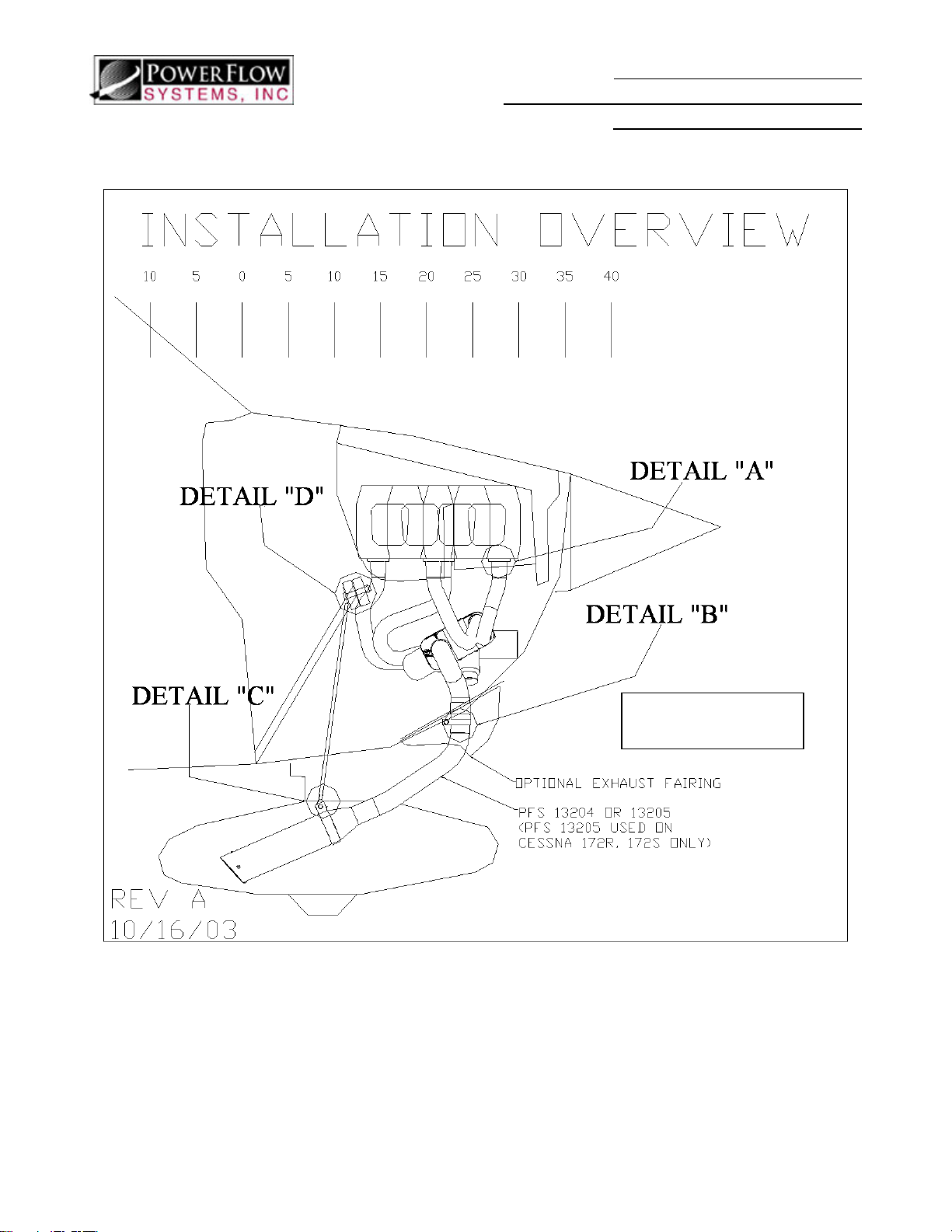
PFS-13204 with Classic
Tailpipe Shown
Page 20 of 28 July 23, 2009
Page 21
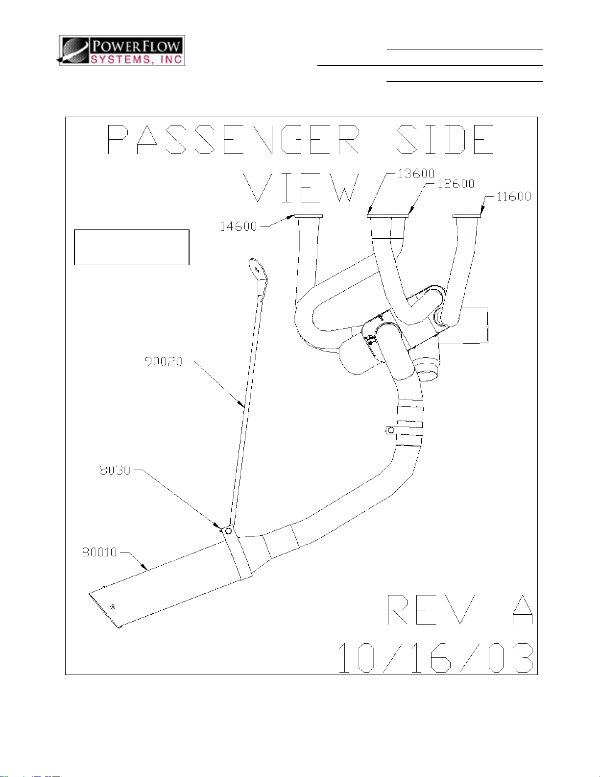
PASSENGER SIDE VIEW - CLASSIC
PFS-13204 with Classic
Tailpipe Shown
Installation Instructions and
Instructions for Continued Airworthiness
Kit: PFS-13204, PFS-13205
PFS-13250-00 Rev G Page 21 of 28 July 23, 2009
Page 22
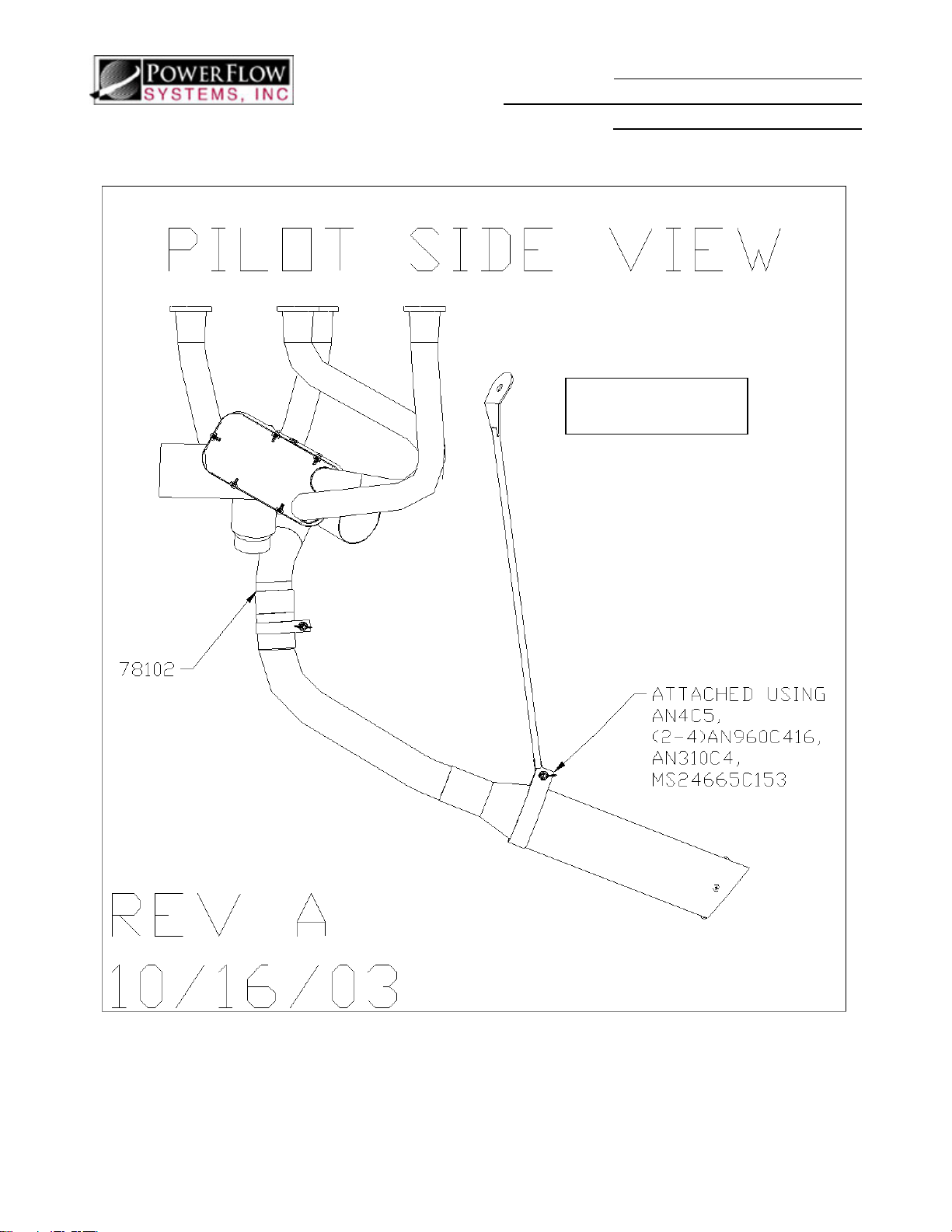
PILOT SIDE VIEW - CLASSIC
Installation Instructions and
Instructions for Continued Airworthiness
Kit: PFS-13204, PFS-13205
PFS-13204 with Classic
Tailpipe Shown
PFS-13250-00 Rev G Page 22 of 28 July 23, 2009
Page 23
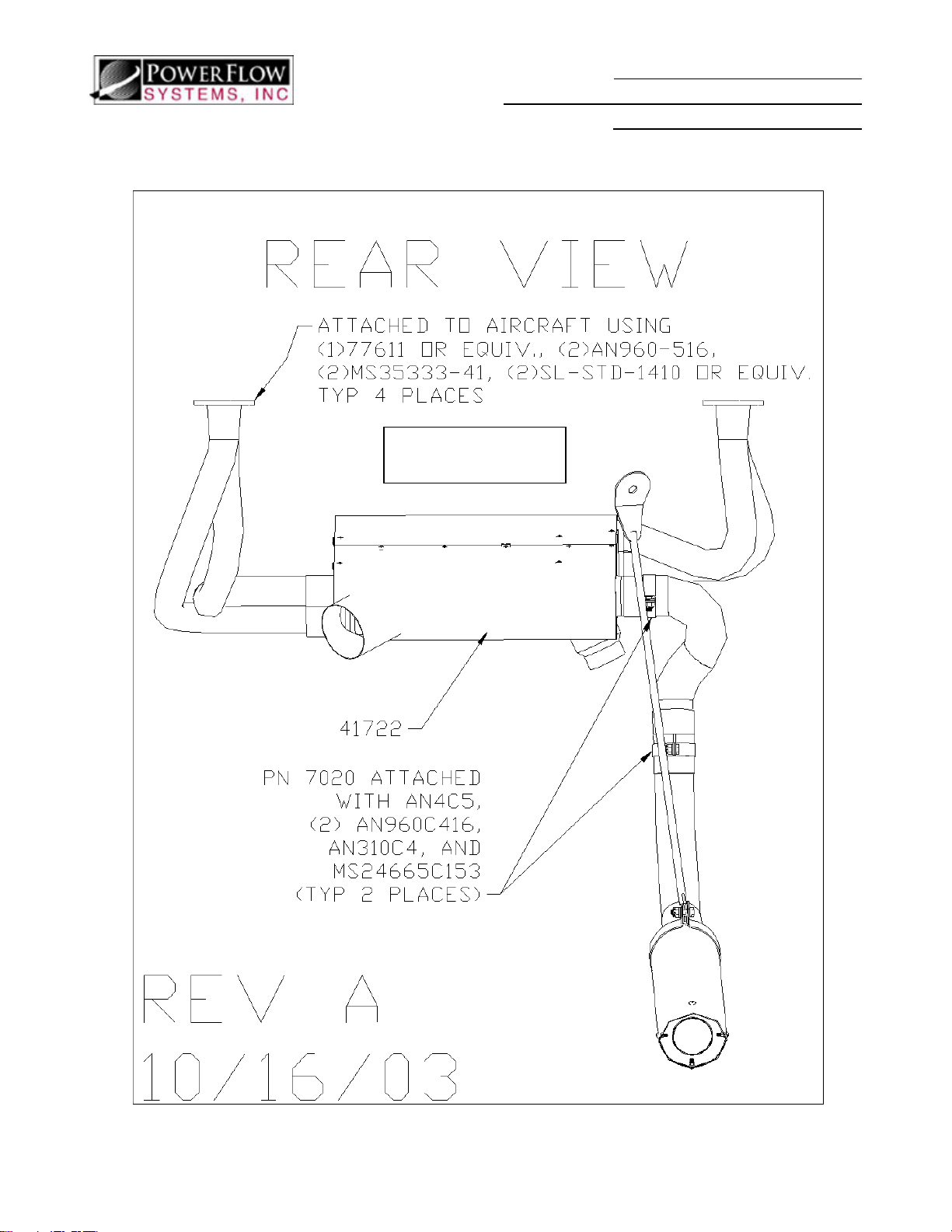
REAR VIEW - CLASSIC
Instructions for Continued Airworthiness
PFS-13204 with Classic
Tailpipe Shown
Installation Instructions and
Kit: PFS-13204, PFS-13205
PFS-13250-00 Rev G Page 23 of 28 July 23, 2009
Page 24
Installation Instructions and
Instructions for Continued Airworthiness
Kit: PFS-13204, PFS-13205
INSTALLATION OVERVIEW – SHORT STACK
SHORT STACK
TAILPIPE
PFS-13250-00 Rev G Page 24 of 28 July 23, 2009
Page 25
Instructions for Continued Airworthiness
K
PASSENGER SIDE VIEW – SHORT STACK
Installation Instructions and
Kit: PFS-13204, PFS-13205
SHORT STAC
PFS-13250-00 Rev G Page 25 of 28 July 23, 2009
Page 26
Instructions for Continued Airworthiness
K
PILOT SIDE VIEW – SHORT STACK
Installation Instructions and
Kit: PFS-13204, PFS-13205
SHORT STAC
PFS-13250-00 Rev G Page 26 of 28 July 23, 2009
Page 27
K
REAR VIEW – SHORT STACK
SHORT STAC
Installation Instructions and
Instructions for Continued Airworthiness
Kit: PFS-13204, PFS-13205
PFS-13250-00 Rev G Page 27 of 28 July 23, 2009
Page 28
 Loading...