

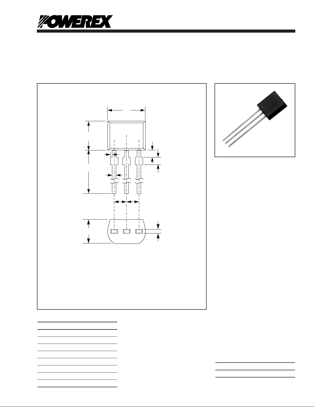
Dimensions Inches Millimeters
A 0.55 Min. 14.0 Min.
B 0.12 Max. 3.0 Max.
C 0.16 4.0
D 0.14 3.55
E 0.098 Max. 2.5 Max.
F 0.016 0.4
G 0.05 ± 0.012 1.27
H 0.018 0.45
Description:
The BS08D bilateral switch is a
silicon planar monolithic integrated
circuit with the electrical characteristics of a bilateral thyristor.The
device is designed to switch at 7
to 9 volts with a 0.01%/°C temperature coefficient and have excellently matched characteristics in
both directions.
Features:
□ Low Switching Voltage of
7 to 9 Volts
□ Excellent Switching Voltage
Temperature Characteristics
(0.01%/°C)
□ High Reliability Devices
□ Gate Electrode Facilitating
Switching Operation Control
and Synchronization.
Applications:
□ Trigger Circuits for Thyristor or
Triac, Oscillators, Timers
Ordering Information:
Example: Select the complete five
digit part number you desire from
the table - i.e.BS08D is a 175mA
Silicon Bilateral Switch.
Type
BS08D
Powerex,Inc., 200 Hillis Street,Youngwood, Pennsylvania 15697-1800 (724) 925-7272
Silicon
Bilateral Switch
BS08D
Outline Drawing
TT-1
➁
GG
D
D
C
B
J
H
A
➀ T2 TERMINAL
➁ GATE
➂ T1 TERMINAL
E
F
➂➀
OUTLINE DRAWING
CONNECTION DIAGRAM

Absolute Maximum Ratings, Ta= 25 °C unless otherwise specified
Ratings Symbol BS08D Units
DC Forward Anode Current I
T
175 mA
Repetitive Peak Forward Current – 1.0 Amperes
(1% Duty Cycle, 10s Pulsewidth), Ta= 100°C
Non-repetitive Peak Forward Current (10s Pulsewidth) – 2.0 Amperes
Power Dissipation P
T
450 mW
DC Gate Current I
G
5mA
Storage Temperature T
stg
-55 to 125 °C
Operating Temperature T
j
-55 to 125 °C
Electrical and Thermal Characteristics, Tj= 25 °C unless otherwise specified
BS08D
Characteristics Symbol Test Conditions Min. Typ. Max. Units
Switching Voltage V
S
Ta= 25°C 7 8 9 Volts
Switching Current I
S
Ta= 25°C ––200 A
Absolute Switching Voltage Difference VS1-VS2 Ta= 25°C ––0.5 Volts
Absolute Switching Current Difference IS1-IS2 Ta= 25°C ––100 A
Holding Current I
H
Ta= 25°C ––1.5 mA
Off-state Current I
D
VD= 5V, Ta= 25°C ––1.0 A
VD= 5V, Ta= 85°C ––10 A
Temperature Coefficient of Switching Voltage – Ta= -55 to 85°C – ±0.01 – %/°C
Peak On-state Voltage V
T
IT= 175mA, Ta= 25°C ––1.4 Volts
Gate Trigger Current I
GT
VD= 5V, Ta= 25°C10– 200 A
Gate Non-trigger Voltage V
GD
VD= 5V, Ta= 85°C 0.2 –– Volts
Powerex,Inc., 200 Hillis Street, Youngwood, Pennsylvania 15697-1800 (724) 925-7272
BS08D
Silicon Bilateral Switch
TT-2

Powerex,Inc., 200 Hillis Street, Youngwood, Pennsylvania 15697-1800 (724) 925-7272
BS08D
Silicon Bilateral Switch
OFF-STATE CURRENT
VS. JUNCTION TEMPERATURE
(TYPICAL)
JUNCTION TEMPERATURE, Tj, (°C)
-40
10
-2
10
-1
10
0
10
1
0 40 80 120-20-60 20 60 100 140
OFF-STATE CURRENT, I
D
, (A)
VD = 5V
SWITCHING VOLTAGE
VS.JUNCTION TEMPERATURE
(TYPICAL)
JUNCTION TEMPERATURE, Tj, (°C)
-60
7.5
7.7
7.9
8.1
8.3
SWITCHING VOLTAGE, V
S
, (VOLTS)
-20 20 60 100 140-40 0 40 80 120
SWITCHING CURRENT
VS. JUNCTION TEMPERATURE
(TYPICAL)
JUNCTION TEMPERATURE, Tj, (°C)
SWITCHING CURRENT, I
S
, (A)
-60 -20 20 60 100 140-40 0 40 80 120
0
80
160
240
320
TYPICAL VALUE
TYPICAL DISTRIBUTION
ON-STATE VOLTAGE
VS. JUNCTION TEMPERATURE
(TYPICAL)
JUNCTION TEMPERATURE, Tj, (°C)
-60
0.80
0.90
1.00
1.10
1.20
1.30
ON-STATE VOLTAGE, V
T
, (VOLTS)
IT = 175mA
-20 20 60 100 140-40 0 40 80 120
HOLDING CURRENT
VS. JUNCTION TEMPERATURE
(TYPICAL)
JUNCTION TEMPERATURE, Tj, (°C)
HOLDING CURRENT, I
H
, (A)
-60 -40 0 40 80-20 20 60 100
0
200
400
600
800
TYPICAL VALUE
TYPICAL DISTRIBUTION
GATE TRIGGER CURRENT
VS. JUNCTION TEMPERATURE
(TYPICAL)
JUNCTION TEMPERATURE, Tj, (°C)
GATE TRIGGER CURRENT, I
GT
, (A)
0 20 40 60 80 100
0
40
80
120
160
TYPICAL VALUE
TYPICAL DISTRIBUTION
VD = 5V
GATE TRIGGER VOLTAGE
VS. JUNCTION TEMPERATURE
(TYPICAL)
JUNCTION TEMPERATURE, Tj, (°C)
GATE TRIGGER VOLTAGE, V
GT
, (VOLTS)
0 20 40 60 80 100
0
0.2
0.4
0.6
0.8
TYPICAL DISTRIBUTION
VD = 5V
TT-3

Powerex,Inc., 200 Hillis Street, Youngwood, Pennsylvania 15697-1800 (724) 925-7272
BS08D
Silicon Bilateral Switch
CIRCUIT SYMBOL
5V
10k
47
A
A
V
V
GATE CHARACTERISTICS
MEASUREMENT CIRCUIT
APPLICATION EXAMPLES
THYRISTOR TRIGGER CIRCUIT EQUIVALENT CIRCUIT
T
2
T
1
G
LOAD
SBS
BS08D
BCR16
HM-8
Triac
VR
200K
AC INPUT
100VAC
R
1
100, 0.25W
R
2
100
0.5W
R
3
15k
(1W)
D
1
D
2
C
2
0.1 F
400WV
C
1
0.47F
25WV
This circuit is useable in such applications as lighting
control circuits, electric heater control, and other load
control applications.
TRIAC TRIGGER CIRCUIT
V
T2
V
T1
V
S2
V
S1
I
S2
I
D2
I
D1
I
H2
I
S1
I
H1
-I
+I
-V +V
STATIC CHARACTERISTICS
LOAD
1k
SBS
BS08D
0.1 F
C
1M
VR
DR
220k
CR2AM-8 CRAC INPUT
100VAC
R
2
This circuit is widely used in DC motor
contol and other control applications.
T
1
T
2
G
TT-4
 Loading...