

Page 1
Climate Control Duplex
Please read and save these instructions. Read carefully before attempting to assemble, install, operate or maintain the product
described. Protect yourself and others by observing all safety information. Failure to comply with instructions could result in
personal injury and/or property damage! Retain instructions for future reference.
Description
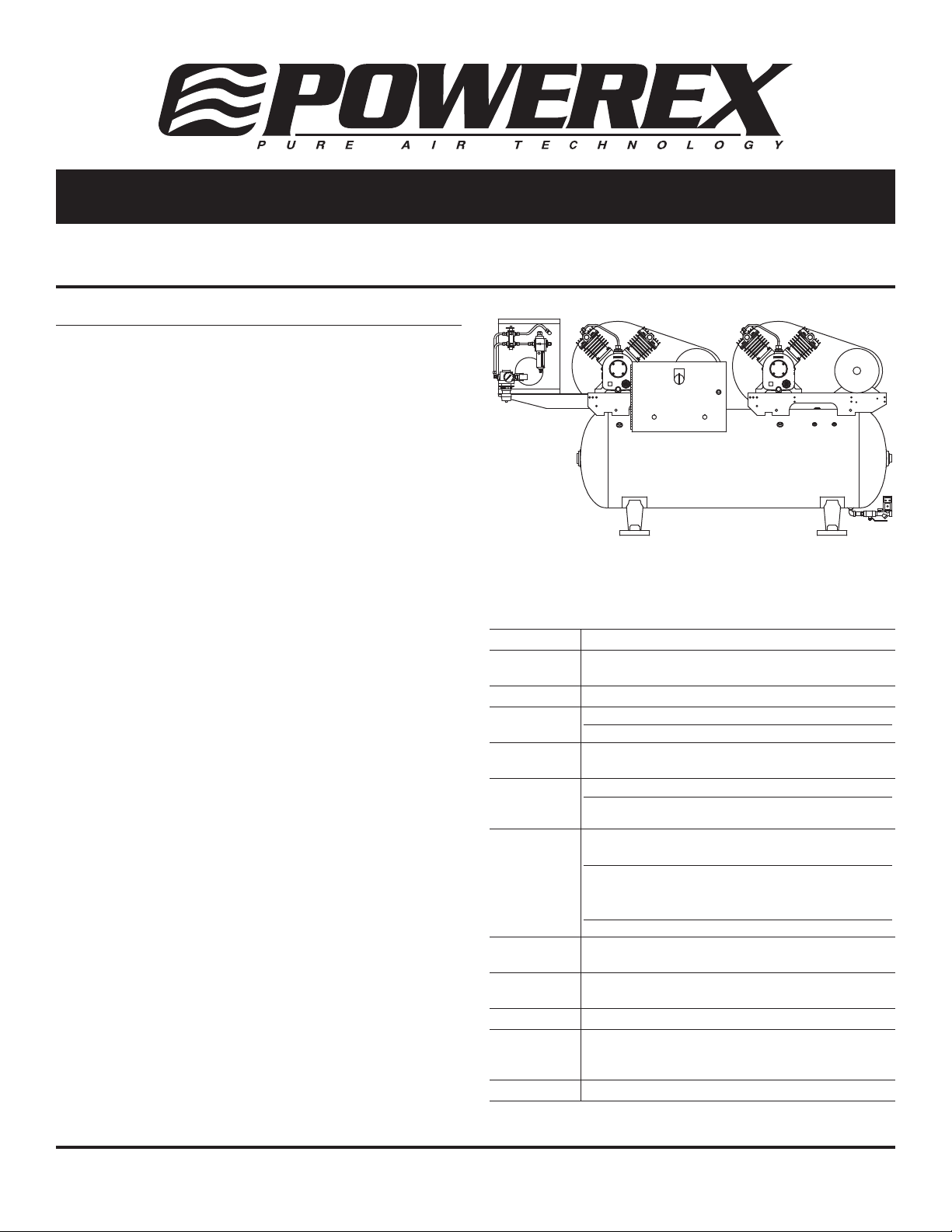
The AD Series Powerex Duplex Air Compressors have been
designed, broken-in and tested to meet the most demanding
specifications for low oil carryover and long life in the
pneumatic climate control industry.
The units consist of two equally rated motor-compressor
assemblies mounted on a single ASME tank. The compressor
motors are NEMA Class B design. The AD Series Compressors
are ideal for instrumentation systems requiring an alternate
compressor for standby or overload capacity. See Table 1 for
motor sizes and air delivery capacities available.
Compressor assemblies are available with or without a factory
mounted basic or deluxe alternator/motor starter package. An
unloading feature is included on all compressors to provide
loadless starting. Models with an alternator are prewired and
ready for operation. Internal wiring allows for shutdown of
either compressor for repair while the other compressor is
running.
An alternating type operation is desirable for many reasons.
When a duplex air compressor is alternated, the temperature
of both units is kept above the ambient dew point to minimize
moisture deterioration and corrosion. Also, the reduction in
on-time provides a lower average head temperature with
reduced oil entrainment potential and improves the motor life
by holding down the average heat rise.
All units are run through a factory break-in and are tested
for air delivery, leakage and power consumption. Tankmounted units are shipped with a proper fill of compressor
oil in the crankcase and are furnished with an intake filter
with a replaceable cartridge. This filter is designed to remove
contaminates in the inlet air, as well as provide a quiet
operation.
All models have conveniently located oil drain and filler ports
to facilitate routine maintenance. Tanks have a condensate
drain valve with an extension for easy access. Mounting bases
are slotted to allow tension adjustments to aid in maintaining
proper compressor and motor alignment while adjusting
tension.
INLET
OUT IN
OUTLET
NORGRENN
40
60
PRESSURE GAGE
80
20
100
0
PSI
Specifications
Product AD Series Powerex Duplex Air Compressors
Performance
Specifications
Lubrication Splash Lubrication System (3/4 HP - 10 HP Models)
Operating
Voltages
Compression
Cycle
Motor
Overload
Protection
Pressure
Settings
Overpressure
Protection
Outlet Air
Connections
Tank Sizes 30 Gallon to 200 Gallon
California
Ordinance
462 (L) (2)
Tank Isolation Standard All Units
See Page 2
1Ø 115 - 280 / 230 Volts, 60 Hz
3Ø 280 - 230 / 460 Volts, 60 Hz
Single-Stage (3/4 HP - 10 HP Models)
1Ø Built-in Thermal Overload (Standard)
3Ø Magnetic Starter and Three Thermal
Overload Heaters (Optional)
Lead
Cut-In: Factory Set at Approximately 70 psig (490 kPa)
Cut-Out: Factory Set at Approximately 90 psig (630 kPa)
Lag
Cut-In: Factory Set at Approximately 60 psig (420 kPa)
Cut-Out: Factory Set at Approximately 80 psig (560 kPa)
ASME Safety Valve Factory Set and Sealed at
Approximately 115 psig (805 kPa)
3/4 inch NPT (30, 60, and 80 Gallon Tanks)
1 inch NPT (120 and 200 Gallon Tanks)
Meets Requirements of this Ordinance
TEST
ON
OFF
6
4
20
30
10
2
8
40
5
0.5
10
0.5
45
min.
sec.
The performance specifications are nominal and conform to acceptable industry standards. For application at conditions beyond these
specifications, consult the local Powerex office. Powerex shall not be liable for damages resulting from misapplication or misuse of its products.
Powerex • 150 Production Drive • Harrison, OH 45030 • USA
IN558203AV 9/11
1-888-769-7979 • www.powerexinc.com
Page 2
Climate Control Duplex
Performance Specifications
Motor Rating
Base Model
AD-107 0.75 1725 980 2.1 1.07 0.71
AD-007 0.75 1725 980 2.1 1.07 0.71
AD-110 1.0 1725 1120 3.5 1.74 1.15
AD-010 1.0 1750 1120 3.5 1.74 1.15
AD-015 1.5 1760 860 4.6 2.3 1.5
AD-020 2.0 1755 1250 6.9 3.4 2.3
AD-030 3.0 1725 1050 10.3 5.2 3.4
AD-050 5.0 1750 1150 19.0 9.5 6.3
AD-075 7.5 1750 950 28.6 14.3 9.5
AD-100 10.0 1765 880 37.8 18.9 12.5
NOTE: 0.75 HP pumps must be used under altitudes of 5000 feet.
Above 5000 feet, 1 HP pumps must be used.
HP RPM 100% Runtime 50% Runtime 33% Runtime
Compressor RPM
Safety Guidelines
This manual contains information that is very important
to know and understand. This information is provided for
SAFETY and to PREVENT EQUIPMENT PROBLEMS. To help
recognize this information, observe the following symbols.
Danger indicates an imminently
hazardous situation which, if
not avoided, WILL result in death or serious injury.
Warning indicates a potentially
not avoided, COULD result in death or serious injury.
Caution indicates a potentially
Notice indicates important
followed, may cause damage to equipment.
hazardous situation which, if
minor or moderate injury.
information, that if not
NOTE: Information that requires special attention.
CALIFORNIA PROPOSITION 65
This product or its power cord
may contain chemicals known
to the State of California to cause cancer and birth defects or
other reproductive harm. Wash hands after handling.
Installation
MOUNTED AND CONNECTED OPTIONS
Deluxe Alternator Package
All Powerex Duplex air compressors may be ordered with
an optional deluxe alternator package consisting of two
magnetic motor starts with thermal overloads, an alternating
coil, a 120 VAC control transformer and a three-position
selector switch. The three-position switch allows for
automatic alternation or only running one unit at a time. This
will allow for service on one unit while other unit is running.
Compressor Capacity ACFM @ 80 psig
Basic Alternator Package
All Powerex duplex air compressors may be ordered with a
simplified line voltage basic alternator package. The basic
alternator package consists of an alternating coil and two
magnetic motor starters. Motor starters are selected and
wired for intended input voltage and are furnished with
properly sized overload heaters.
Automatic Tank Drain
Powerex air compressors may be ordered with a manual
or electric type automatic tank drain. A manual drain
attachment is furnished with each unit.
Vibration Dampening Pads
Waffle type design vibration pads are provided as standard
equipment.
Operation
Factory calibrated DPST pressure switches provide lead and lag
settings. When using an alternator-starter package, the lead
switch energizes the alternator and the alternator activates
the compressor that was on standby during the previous cycle.
If the demand exceeds the capacity of one compressor, the lag
switch will cause both compressors to run simultaneously. Upon
failure of either compressor, the lag switch will continue to
activate the workable compressor.
Single-phase motors (3/4 HP & 1 HP) have built-in overload
protection with manual reset. Three-phase motors require
a magnetic starter and three overload heaters. Heaters are
included with three-phase compressors that have a factory
mounted alternator.
NOTE: All pump models operate turning clockwise opposite
the motor shaft / pump flywheel / belt guard side of the unit.
Improper rotation will cause oil to spray out of the breather
vent opening.
2
Page 3

Climate Control Duplex
Operation (Continued)
LUBRICATION
Check lubricating oil level at gauge. Refill if necessary. See
Figure 1.
Change oil according to maintenance schedule. Before
draining oil, remove oil supply cap and loosen oil drain cap to
release trapped air. Use Mobil Rarus 427® or Mobil DTE heavy
oils.
Dispose of oil in accordance
with state or local codes.
Remove cap and use funnel
to add oil
Round (Red)
Full
Low
Oil drain
cap
Oil
gauge
AUTO E-DRAIN ASSEMBLY (See Figure 2)
NOTE: The automatic E-drain is assembled to tank.
1. Plug E-drain into 115V power outlet supply.
2. Adjust times accordingly.
Manifold Assembly
TEST
ON
OFF
6
4
20
30
2
10
8
40
5
0.5
10
0.5
45
sec.
min.
Auto E-Drain
Figure 1
Single
Disconnect
Field
Supplied
Red
Red
L
L 2L
1
Red
IT1IT2IT
Motor
1
3
Black
Blue
3
1M
Red
Red
Black
Blue
Alt L Alt R
Alt C
Alt
A251
A251
2M
PS 1
2M
A252
PS 2
Oil gauge close-up
Lag Switch
Cut In: 60 psig (420 kPa)
Cut Out: 80 psig (560 kPa)
L
1
L
2
L
3
2T12T22T
Motor
2
3
PS 2
Starter
Overload
Lead Switch
Cut In: 70 psig
(490 kPa)
Cut Out: 90 psig
(630 kPa)
Figure 2
A1 A2
1M
L 1L 2L
1
2
IT
IT
Motor
1
Lag Switch
Cut In: 60 psig
3
(420 kPa)
Cut Out: 80 psig
(560 kPa)
L
1L 2L 3
A1
A2
Alt
FU
FU
3
IT
X2
X1
2M
2T12T22T
Motor
2
3
FU
Selector
Switch
Lead Switch
Cut In: 70 psig
(490 kPa)
Cut Out: 90 psig
(630 kPa)
Figure 3 - Basic Alternator package wiring diagram for
three-phase units
Figure 4 - Deluxe Alternator package wiring diagram for
three-phase units
3
Page 4

Climate Control Duplex
Unit Dimensions (inches *) and Shipping Weights (pounds *)
Optional Dryer
(3 HP and under)
Discharge
A
Plug
B
F
D
G
Base
Model A
AD-107-1XX 41.50 24.00 17.75 36.50 18.00 15.75 12.25 57.25 298 278
AD-007-1XX 41.50 24.00 17.75 36.50 18.00 15.75 12.25 57.25 298 278
AD-107-3XX 63.60 27.00 20.00 42.50 40.00 18.00 14.60 70.00 463 443
AD-007-3XX 63.60 27.00 20.00 42.50 40.00 18.00 14.60 70.00 463 443
AD-110-1XX 41.50 24.00 17.75 36.50 18.00 15.75 12.25 57.25 297 277
AD-010-1XX 41.50 24.00 17.75 36.50 18.00 15.75 12.25 57.25 297 277
AD-110-3XX 63.60 25.00 20.00 43.30 40.00 18.00 14.60 69.80 462 442
AD-010-3XX 63.60 25.00 20.00 43.30 40.00 18.00 14.60 69.80 462 442
AD-015-1XX 41.50 25.80 17.75 38.75 18.00 15.75 12.25 57.10 322 302
AD-015-3XX 63.75 25.00 20.00 43.30 40.00 18.00 14.60 69.80 487 467
AD-020-3XX 63.75 26.00 20.00 43.60 40.00 18.00 14.60 80.60 512 492
AD-030-3XX 64.10 25.4 20.00 43.70 40.00 18.00 14.60 80.25 715 695
AD-030-4XX 70.75 28.10 24.00 48.20 42.00 18.00 16.80 81.75 845 825
AD-050-4XX 71.60 29.00 24.00 50.50 42.00 18.00 16.80 -- 988 968
AD-050-5XX 82.60 33.25 30.50 56.60 42.00 22.00 18.75 -- 1213 1193
AD-075-4XX 71.58 29.57 24.80 54.25 42.00 18.00 16.80 -- 1113 1088
AD-075-5XX 82.62 33.25 30.00 59.40 42.00 22.00 18.75 -- 1338 1313
AD-100-5XX 82.62 33.25 30.00 59.40 42.00 22.00 18.75 -- 1553 1528
* inches x 2.54 = centimeters; pounds x 0.454 = kilograms
** Add 60.0 pounds for units equipped with a factory mounted air dryer
B
with
Alternator
B
without
Alternator C D E F G
E
Unit Weight **
with
Alternator
without
Alternator
C
4
Page 5

Maintenance Schedule
Climate Control Duplex
Action
Item
Tank Drain moisture
Inlet air
filter
Pump
flywheel
Compressor
fins
Oil change Replace
Compression
rings
Check oil Inspect
V-belt
Pressure
switch
Magnetic
starter
Safety valve
Pressure
gauge
needed
Inspect,
Replace
Clean
Clean
Replace
Inspect,
Replace
Confirm
operation
Inspect
Confirm
operation
Inspect
Operating Hours
RemarksDaily 500 1500 2500 5000 10,000 15,000 20,000
l
l s
l l l l
l
s
s
l
l s s s s
l l
l l
l
l
Drain tank daily
Every 2500 hours
or less
Every 2500 hours
or less
Every 1500 hours
See Note 3
Replace if contact
points deteriorated
Every 2500 hours
or 6 months
Every 2500 hours
or less
l Inspect
s Replace
NOTES:
1. Inspect and perform maintenance periodically according to maintenance schedule.
2. The maintenance schedule relates to the normal operating conditions. If the circumstances and load condition
are adverse, shorten the cycle time and do maintenance accordingly.
3. The tension of the V-belt should be adjusted during initial start up and inspected every 1,500 hours afterwards.
Proper belt tension for 3/4 to 3 HP units is 2-3 lbs. / 0.5 inch deflection; for 5 to 10 Hp units, 4-6 lbs. / 0.5 inch deflection.
Oil Capacity Chart
Model HP
LPS007 0.75 0.44 0.12
LPS010A 1.0 0.44 0.12
LPS020A 1.5 / 2 0.44 0.12
LPS030A 3 0.70 0.20
LPS050A 5 1.03 0.35
LPS075A 7.5 1.70 0.45
LPS100A 10 1.70 0.45
Oil Capacity
0 to High (liters)
Oil Range
Low to High (liters)
5
Page 6

Climate Control Duplex
L
G (inside belt guard)
J
H (inside belt guard)
D
M
B
C
A
E
K
E
F
Replacement Parts List
Quantity Shipping Code
Item Description Required Weight (lbs.) Number
A PUMP AND FLYWHEEL:
Motor HP 3/4 2 38 A-007-6001AP
1 2 38 A-010-6001AP
1-1/2, 2 2 51 A-020-6001AP
3 2 93 A-030-6001AP
5 2 120 A-050-6001AP
7-1/2 2 175 A-075-6001AP
10 2 198 A-100-6001AP
B VALVE KIT: Includes valve plate, spacer and head gasket
Motor HP 3/4, 1 2 0.5 A-010-6002AP
1-1/2, 2 2 0.5 A-010-6002AP
3 4 0.7 A-030-6002AP
5 4 1.2 A-050-6002AP
7-1/2 4 1.2 A-075-6002AP
10 6 1.2 A-075-6002AP
C RING/CYLINDER KIT: Includes all compression rings, oil control rings, cylinder, gasket and sealant
Motor HP 3/4, 1 2 4.8 A-010-6004AP
1-1/2, 2 2 4.8 A-010-6004AP
3 4 5.5 A-030-6004AP
5 4 10 A-050-6004AP
7-1/2 4 10 A-075-6004AP
10 6 10 A-075-6004AP
D INTAKE FILTER ELEMENT:
Motor HP 3/4, 1 2 0.1 A-010-6023AP
1-1/2, 2 2 0.2 A-010-6023NP
3 4 0.2 A-010-6023NP
5 4 0.2 A-010-6023NP
7-1/2 4 0.2 A-010-6023NP
10 4 0.2 A-010-6023NP
E IN-TANK CHECK VALVE:
Motor HP Size
3/4 Through 3 1/2 inch MPT x 1/2 inch FPT 2 0.3 A-010-6008
5 Through 10 3/4 inch MPT x 3/4 inch FPT 2 0.4 A-075-6008
F SAFETY RELIEF VALVE: Set at approximately 115 psig (805 kPa)
3/4 Through 5 HP Models 1 0.1 A-050-6009
7-1/2 Through 10 HP Models 1 0.2 A-200-6009
6
Page 7

Climate Control Duplex
Replacement Parts List (Continued)
Quantity Shipping Code
Item Description Required Weight Number
G BELT:
Motor HP Size
3/4 A-42 2 0.3 A-010-6006AP
1 A-43 2 0.3 A-010-6006AP
1-1/2 AX-46 2 0.3 A-015-6006AP
2 A-59 2 0.4 A-020-6006AP
3 B-62 2 0.4 A-030-6006AP
5 B-67 2 1.6 A-050-6006AP
7-1/2 B-69 4 2.0 A-075-6036AP
7-1/2 B-75 4 2.0 A-075-6056AP
10 A-80 4 2.4 A-100-6006AP
H MOTOR PULLEY:
Motor HP Type
3/4 1A-5.7 inch P.D., 5/8 inch Bore 2 3.9 A-007-6007AP
1 (1Ø) 1A-5.7 inch P.D., 5/8 inch Bore 2 3.2 A-110-6007AP
1 (3Ø) 1A-6.0 inch P.D., 7/8 inch Bore 2 3.2 A-010-6007AP
1-1/2 1A-5.5 inch P.D., 7/8 inch Bore 2 5.6 A-015-6007AP
2 1BK-8.0 inch P.D., 7/8 inch Bore 2 5.2 A-020-6007AP
3 1B-8.0 inch P.D., 1-1/8 inch Bore 2 6.3 A-030-6007AP
5 1B-9.4 inch P.D., 1-1/8 inch Bore 2 7.6 A-050-6007AP
7-1/2 2B-8.6 inch P.D., 1-3/8 inch Bore 2 12.5 A-100-6007AP
10 2B-8.6 inch P.D., 1-3/8 inch Bore 2 13.5 A-100-6007AP
J PRESSURE ELECTRIC SWITCHES: (For all models)
Lead Switch: Set at approximately
70 psig (490 kPa) cut-in and
90 psig (630 kPa) cut-out 1 0.9 A-100-6010
Lag Switch: Set at approximately
60 psig (420 kPa) cut-in and
80 psig (560kPa) cut-out 1 0.9 A-100-6011
K TANK:
Motor HP Tank Size
3/4 Through 1-1/2 30 gallon 1 134.0 A-015-6030AP
3/4 Through 1-1/2 80 gallon 1 235.0 A-015-6080AP
2 & 3 80 gallon 1 243.0 A-030-6080AP
2 & 3 120 gallon 1 398.0 A-030-6120AP
5 & 7-1/2 120 gallon 1 415.0 A-075-6120AP
5 Through 10 200 gallon 1 677.0 A-100-6200AP
L BELT GUARD:
Motor HP
3/4 Through 1-1/2 2 2.4 A-015-6012AP
2 2 12.5 A-020-6012AP
3 2 12.5 A-030-6012AP
5 2 12.5 A-075-6012AP
7-1/2
7-1/2
10 2 12.5 A-100-6012AP
M MOTOR:
Motor HP
3/4 (1Ø) 2 32.0 MC301510AV
3/4 (3Ø) 2 25.0 MC301511AV
1 (1Ø) 2 36.0 MC022371AV
1 (3Ø) 2 36.0 MC301512AV
1-1/2 (1Ø) 2 42.0 MC022320AV
1-1/2 (3Ø) 2 44.0 MC301513AV
2 (1Ø) 2 65.0 MC022317AV
2 (3Ø) 2 44.0 MC303300AV
3 2 58.0 MC303301AV
5 2 70.0 MC303303AV
7-1/2 2 73.0 MC303308AV
10 2 124.01 MC303310AV
(120 Gal) 2 12.5 A-075-6012AP
(200 Gal) 2 12.5 A-075-6022AP
7
Page 8

Climate Control Duplex
Powerex Limited Warranty
Warranty and Remedies.
(a) General. Powerex warrants each Compressor System, Vacuum System, Vacuum Pump, Compressor Air-End, or Powerex branded
Accessory (collectively “Products”, individually each a “Product”) to be free from defects in material and workmanship (“Defects”)
at the date of shipment. EXCEPT AS SET FORTH BELOW, NO OTHER WARRANTY, WHETHER EXPRESS OR IMPLIED, INCLUDING ANY
WARRANTY OF MERCHANTABILITY OR FITNESS FOR A PARTICULAR PURPOSE, SHALL EXIST IN CONNECTION WITH THE SALE OR USE
OF SUCH PRODUCTS. TO THE EXTENT PERMITTED BY LAW, ANY AND ALL IMPLIED WARRANTIES ARE EXCLUDED. All claims under this
warranty must be made in writing and delivered to Powerex, or such claim shall be barred. Upon timely receipt of a claim, Powerex shall
inspect the Product claimed to have a Defect, and Powerex shall repair, or, at its option, replace, free of charge, any Product which it
determines to have had a Defect at the time of shipment from Powerex; provided, however, that if circumstances are such as to preclude
the remedying of Defect by repair or replacement, Powerex shall, upon return of the Product, refund to buyer any part of the purchase
price of such Products paid to Powerex. Freight for returning Products to Powerex for inspection shall be paid by buyer. The warranties
and remedies herein are the sole and exclusive remedy for any breach of warranty or for any other claim based on any Defect, or nonperformance of the Products, whether based upon contract, warranty or negligence.
b) Initial Period of Warranty – Parts and Labor. Powerex warrants and represents all Products shall be free from Defects for the
first twelve (12) months from the date of shipment by Powerex, or five thousand (5,000) hours of use, whichever occurs first. During
such warranty period, Powerex shall be fully liable for all Defects in the Products (the “Product Defects”), i.e., all costs of repair or
replacement, which may include “in and out” charges, so long as the Products are located in the continental United States, and the
Products are reasonably located and accessible by service personnel for removal. “In and out” charges include the costs of removing a
Product from buyer’s equipment for repair or replacement.
(c) Additional Period of Warranty – Parts Only (No Labor). In addition to the above, Powerex warrants each Powerex branded
Compressor Air-End, and Vacuum Pump shall be free of Defects for a period of thirty-six months from the date of shipment of Product, or
10,000 hours of use, whichever occurs first. Supplier’s repair or replacement of any Product shall not extend the period of any warranty of
any Product. This warranty applies to the exchange of part(s) found to be defective by an Authorized Powerex Service Center only.
(d) Coverage. The above mentioned warranty applies to Powerex manufactured units or systems only.
(e) Exceptions. Notwithstanding anything to the contrary herein, Powerex shall have no warranty obligations with respect to Products:
(i) that have not been installed in accordance with Powerex’s written specifications and instructions;
(ii) that have not been maintained in accordance with Powerex’s written instructions;
(iii) that have been materially modified without the prior written approval of Powerex; or
(iv) that experience failures resulting from operation, either intentional or otherwise, in excess of rated capacities or in an otherwise
improper manner.
(f) The warranty provided herein shall not apply to: (i) any defects arising from corrosion, abrasion, use of insoluble lubricants, or
negligent attendance to or faulty operation of the Products; (ii) ordinary wear and tear of the Products; or (iii) defects arising from
abnormal conditions of temperature, dirt or corrosive matter; (iv) any OEM component which is shipped by Powerex with the original
manufacturer’s warranty, which shall be the sole applicable warranty for such component.
Limitation of Liability. TO THE EXTENT ALLOWABLE UNDER APPLICABLE LAW, NOTWITHSTANDING ANYTHING TO THE CONTRARY
HEREIN, UNDER NO CIRCUMSTANCES SHALL POWEREX BE LIABLE FOR ANY INCIDENTAL, CONSEQUENTAL, PUNITIVE, SPECULATIVE OR
INDIRECT LOSSES OR DAMAGES WHATSOEVER ARISING OUT OF OR IN ANY WAY RELATED TO ANY OF THE PRODUCTS OR GOODS SOLD
OR AGREED TO BE SOLD BY POWEREX TO BUYER. TO THE EXTENT ALLOWABLE UNDER APPLICABLE LAW, POWEREX’S LIABILITY IN ALL
EVENTS IS LIMITED TO, AND SHALL NOT EXCEED, THE PURCHASE PRICE PAID.
Warranty Disclaimer. Powerex has made a diligent effort to illustrate and describe the Products in this literature accurately; however,
such illustrations and descriptions are for the sole purpose of identification, and do not express or imply a warranty that the Products are
merchantable, or fit for a particular purpose, or that the Products will necessarily conform to the illustrations or descriptions.
Product Suitability. Many jurisdictions have codes and regulations governing sales, construction, installation, and/or use of Products for
certain purposes, which may vary from those in neighboring areas. While Powerex attempts to assure that its Products comply with such
codes, it cannot guarantee compliance, and cannot be responsible for how the product is installed or used. Before purchase and use of a
Product, please review the Product applications, and national and local codes and regulations, and be sure that the Product, installation,
and use will comply with them.
Claims. Claims pertaining to the Products, with the exception of warranty claims, must be filed with Powerex within 6 months of the
invoice date, or they will not be honored. Prices, discounts, and terms are subject to change without notice or as stipulated in specific
Product quotations. All agreements are contingent upon strikes, accidents, or other causes beyond our control. All shipments are
carefully inspected and counted before leaving the factory. Please inspect carefully any receipt of Products noting any discrepancy or
damage on the carrier’s freight bill at the time of delivery. Discrepancies or damage which obviously occurred in transit are the carrier’s
responsibility and related claims should be made promptly directly to the carrier. Returned Products will not be accepted without prior
written authorization by Powerex and deductions from invoices for shortage or damage claims will not be allowed. UNLESS OTHERWISE
AGREED TO IN WRITING, THESE TERMS AND CONDITIONS WILL CONTROL IN ANY TRANSACTION WITH POWEREX any different
or conflicting terms as may appear on any order form now or later submitted by the buyer. All orders are subject to acceptance by
Powerex.
Powerex • 150 Production Drive • Harrison, OH 45030 • USA
1-888-769-7979 • www.powerexinc.com
8
 Loading...