

Page 1
Page 2
Page 3

Page 4

Page 5

5.2
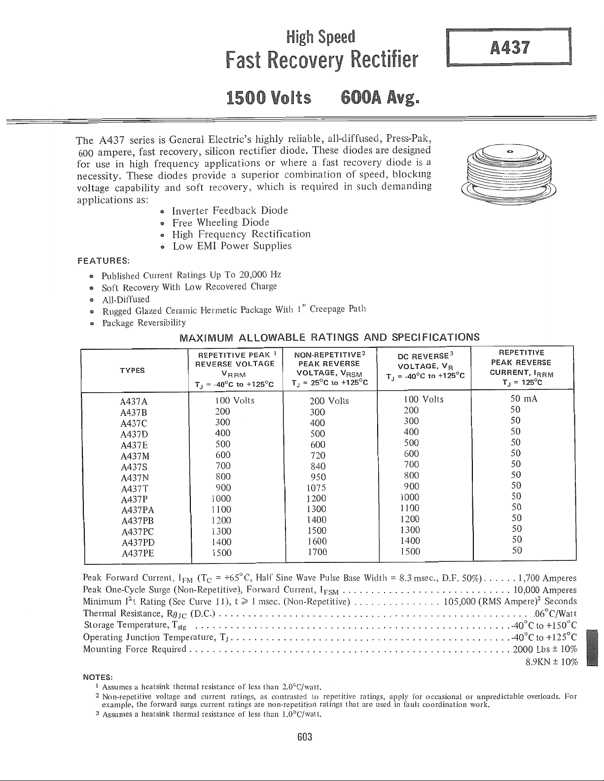
A437
Condensed Electrical and Thermal Characteristics and Ratings
RECTIFIERS
600
TO
1000
6
JEDECTYPE
GETYPE
SPECIFICATIONS
IFM(AV)
V
(Rep)
RM
IFM
(Surge)
2
t
I
T
J
RSJC
V
FM
QR(REC)
tIT
V
F
RSJC
Package Outline No.
Max
Mounting Force (Lbs/Kn)
Expanded Electrical Characterization, see page:
109.1
Max. average forward
Tc
= (0C)
Max. repetitive peak reverse voltage (V)
Max. peak one cycle, non-recurrent
surge current
@ max. rated load conditions (A)
Max. non-repetitive for 1.5 msec (A 2sec)
Operating junction temperature range
Max. thermal resistance,
junction-to-case (OC/W)
Max. peak forward voltage drop @ rated
IF(AV)
@T
c
Reverse recovered charge @ rated T
Reverse recovery time @ rated T
"
Max. forward
voltage drop
for the current
range:
Transient thermal(2)
resistance for
time:
(1
(1
phase operation)
= (0C)
(1
phase operation)
phase operation) 50 Hz.
(I)
60 Hz.
J
(ILS)
J
IM1N(A)
IMAX(A)
A
B
C
D
TM1N(S)
TMAX(S)
F
G
(0C)
(ILC)
AMPERES
600
65
100-1500 100-1500
9000 9000
10000 10000
140,000
-40
to
.06
2.0 1.9
25
100
3.5
10 10
9000 9000
.348 .348
.1
.0002 .0002
.008 .008
.001
.01 .01
.33
.63 .63
183
2000/8.9 2000/8.9
168
125
650
65
140,000
-40
.045
25
100
3.5
.001
.33
109.1
to
.1
155
182
750
100
1600-3000
9000
10000
200,000
125
-40
to
175
.06
1.25
25
-
-
10
8000 10000 7000
-.13
.22 0.192 .04
.0006 .00067 .0002
-.02
.001 .001 .001
.1
.05 0.29
.42 0.61 .6
182 183 183
2200/9.8 2000/8.9
N.A.
750 1000
83
1600-3200
9500
10000
200000
-40
to 200
.06 .06
1.7 1.55
25 25
2000 -
12
200
0.102 .38
-.021
.01 .01
167
183
113
100-1500
9500
10000
200000
-40
to 200
-
10
.003
.32
2000/8.9
164
(I)Voltage Drop Model:
(2)Transient Thermal Resistance Model:
= A + B . LN(I) + C . I + Dy'I
V F
RSJC = F·
to
115
 Loading...