

Page 1
High
Speed
145.73
11/77
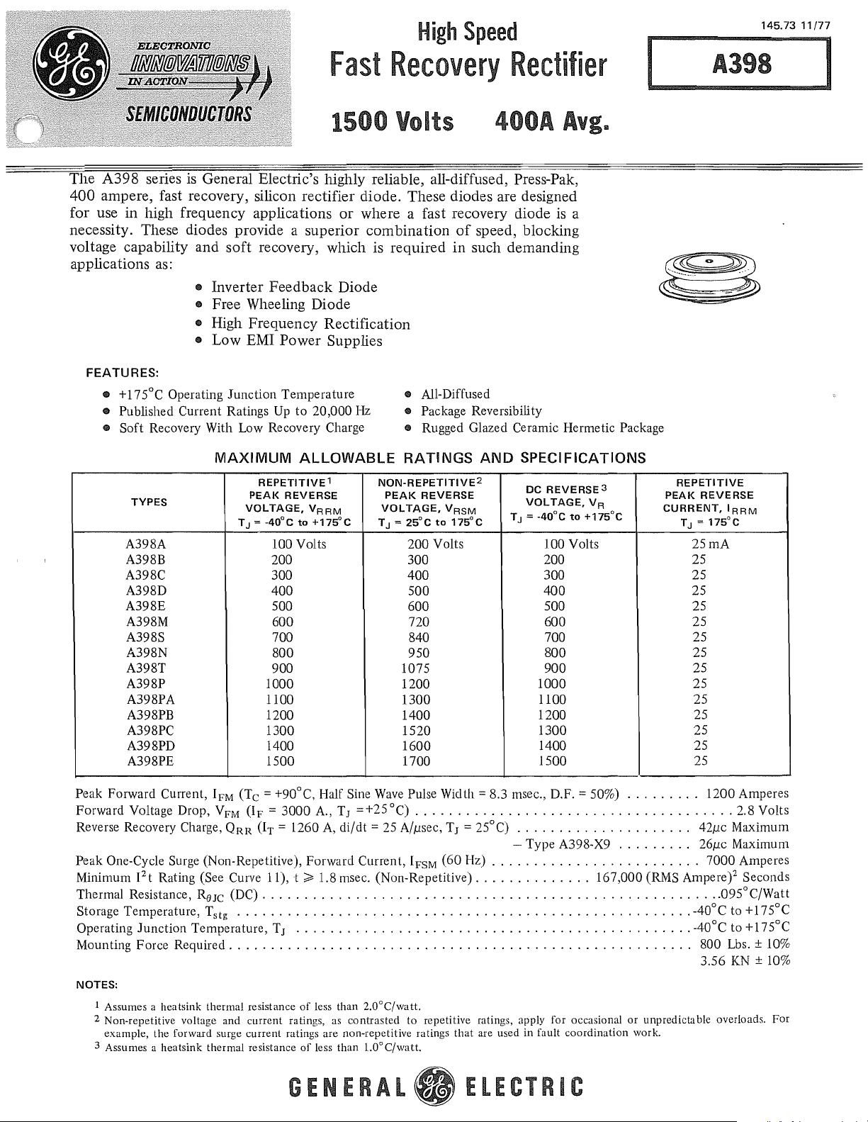
The A398 series
Fast
1500 Volts
is
General Electric's highly reliable, all-diffused, Press-Pak,
Recovery
Rectifier
400A
Avg
400 ampere, fast recovery, silicon rectifier diode. These diodes are designed
for use
necessity. These diodes provide a superior combination
in
high frequency applications
or
where a fast recovery diode
of
speed, blocking
is
voltage capability and soft recovery, which is required in such demanding
applications
as:
• Inverter Feedback Diode
• Free Wheeling Diode
• High Frequency Rectification
• Low EMI Power Supplies
FEATURES:
ED
+175°C Operating
ED
Published Current Ratings Up
ED
Soft
Recovery With Low Recovery Charge • Rugged Glazed Ceramic Hermetic Package
Junction
MAXIMUM
REPETITIVE
TYPES
A39SA 100 Volts
A39SB
A39SC
A39SD
A39SE 500
A39SM
A39SS 700
A39SN
A39ST
A39SP 1000
A39SPA 1100
A39SPB
A39SPC
A39SPD 1400
A39SPE
PEAK
VOLTAGE,
TJ = -40°C
200 300
300
400
600
SOO
900
1200
1300
1500
Temperature
to
20,000 Hz
ALLOWABLE RATINGS
1
REVERSE
V
RRM
to
+175°C
• All-Diffused
ED
Package Reversibility
NON-REPETITIVE2
PEAK
REVERSE
VOL
TAGE,
V
TJ =
25°C
200
400
500
600
720
S40
950
1075
1200
1300
1400
1520
1600
1700
RSM
to
175°C
Volts 100 Volts
AND
SPECIFICATIONS
DC
REVERSE3
VOLTAGE,V
T
= -40°C
J
200
300 25
400
500 25
600 25
700
SOO
900
1000
1100
1200
1300
1400
1500 25
to
a
+175°C
R
..
A398
··~·~·o
........
,
.••
,.
.'
-..;.::-.~".
B
REPETITIVE
PEAK
REVERSE
CURRENT,
TJ =
IRRM
175°C
25mA
25
25
25
25
25
25
25
25
25
25
IFM
(Tc
Peak Forward Current,
Forward Voltage Drop, V
Reverse Recovery Charge,
Peak One-Cycle Surge (Non-Repetitive), Forward Current, I
Minimum
Thermal Resistance,
Storage Temperature, Tstg ,
Operating
Mounting Force Required
NOTES:
1 Assumes a heatsink thermal resistance
2 Non-repetitive voltage and current ratings, as contrasted to repetitive ratings, apply for occasional
3 Assumes a heatsink thermal resistance
1
Junction
example,
2
t Rating (See Curve 11), t ~ I.S
ROJe
Temperature, T
the
forward surge current ratings are non-repetitive ratings that are used in fault
= +90°C, Half Sine
(IF
=
FM
QRR
(DC),
..... , ..
3000
(IT
=
....
.... , ... , ...
J
A., TJ =+25°C)
1260
A,
, . _ ,
,.,"
, . , . ,
of
less than
of
less
GENERAL
Wave
Pulse Width = S.3 msec., D.F. = 50%) . , , . , . ,
, . ' , , ,
di/dt
= 25 A//lsec, TJ = 25°C) , , , , . ,
, ,
FSM
..
msec. (Non-Repetitive)
..
_ , , , , , . , . ,
' , ,
.........
•.•.•....•.
... , ...
2.0°C/watt.
than
1.00 C/watt.
(60
.....
, . , . ,
,
......
, ,
.... , ...
.. , ....
Hz) _ . , , , ,
.......
, , . , ,
ELECTRIC
-
.. , ...
_ . , • ,
, ' , , . , ,
, . ,
.. , ..
Type
...
,
....
.....
, , . _ , , ,
.............
...
A39S-X9
, , . , _ ' . ,
_ , , , , _ ,
coordination
, . ' . , . , . , , . ,
, ,
..
, . , , , ,
....
..... , ..
, .
167,000
.....
..........
(RMS
.....
, ,
,
or
unpredictable overloads, For
work,
..
.....
.,
42/lc Maximum
. . .
..
26/lc Maximum
Ampere?
, ,
....
....
_40°C to +175°C
.. , ..
_40°C to +175°C
, .
,.
SOO
3.56 KN
1200
Amperes
2,S Volts
7000
Amperes
Seconds
_095°C/Watt
Lbs. ± 10%
± 10%
Page 2
10,000
Ul
W
0:
W
0..
::IE
<
I
I-
~
1000
0:
0:
::J
U
o
0:
;
0:
~
100
Ul
::J
o
W
Z
~
Z
~
;!:
I-T
•
J
/ I
1.
I I
.4
175'CHT
'/
•
J
/1
1.0
INSTANTANEOUS
MAXIMUM
/
/'
,.-
25'C
2.0
FORWARD
3.0
FORWARD
4.0
VOLTAGE - VOLTS
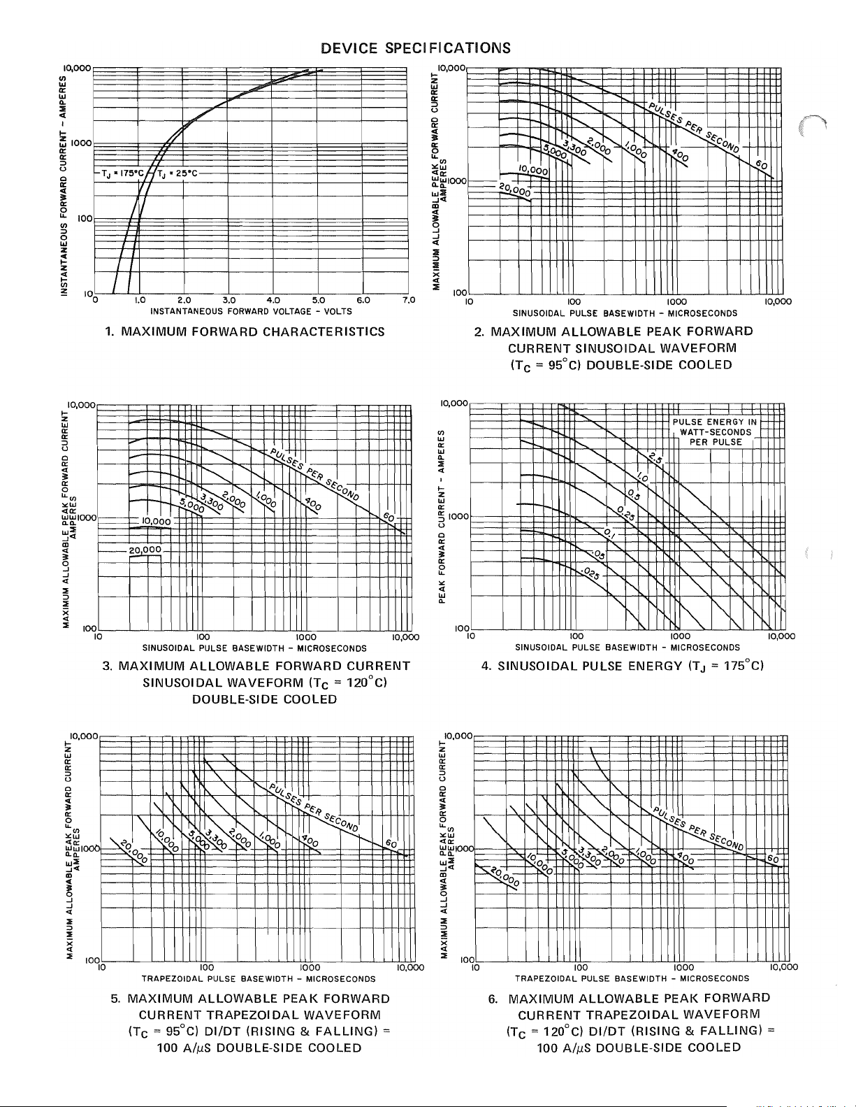
CHARACTERISTICS
DEVICE
5.0
SPECIFICATIONS
10,000
I-
Z
w
0:
0:
::J
U
o
0:
;
~
Ul
><w
<0:
~~Iooo
w:l!
..J<
m
;
o
..J
..J
<
~
!
X
<
6.0
7.0
::IE
100
-
-<0000
10
r--
,
t"--I'-
~o
,0
"u(,
PEAK
..........
-
.........
-
1
~d.l
_'DODO
2.
MAXIMUM
e90~
SINUSOIDAL PULSE BASE WIDTH - MICROSECONDS
CURRENT
["-.,
~
......
~o~
t"--
100
ALLOWABLE
SINUSOIDAL
(TC = 95°C) DOUBLE-SIDE COOLED
$~$
I"h::
"~~
1I1
~COl\to-
"~
1000
",
FORWARD
WAVEFORM
6'0
10,000
10,000
I-
Z
W
0:
0:
::J
U
o
0:
;
0:
o
U,Ul
><w
<0:
i---
~~Iooo
w::E
..J<
m
<
I---~~
:=
o
..J
..J
<
::Ii
::J
::Ii
X
<
::Ii
100
10
3.
10,00 I-0
Z
W
0:
0:
::J
U
o
0:
;
0:
o
U,
Ul
><w
<0::
000
~qo-
~~I
I "
w::E
..J<I
m
l
..J
..J
<
:IE
::J
:IE
X
<I
::Ii
100
10
.........
........
.............
""-
d
-
r.Aoo~'o~
-10,000
SINUSOIDAL PULSE BASE WIDTH - MICROSECONDS
MAXIMUM
",-"",
100
ALLOWABLE
SINUSOIDAL
..,f;U(,$
~$
I"--
-(0
0
r--9
FORWARD
WAVEFORM
1K-9
I
~
1000
DOUBLE-SIDE COOLED
I'\.
'\.
"-
I'--
'\..
1\
1\
\
00
TRAPEZOIDAL PULSE BASE WIDTH MICROSECONDS
5.
MAXIMUM
CURRENT
(Tc
-t
/0
"
~o
'~~~~
-~O
ALLOWABLE
= 95°C)
~~
""
100
TRAPEZOIDAL
DliDT
"u($
r-...
'"
"<.00
_
....
0
PEAK
(RISING &
~$
"~~
U
'100
1000
WAVEFORM
100 AiMS DOUBLE-SIDE COOLED
$
~~o
I"--
CURRENT
(Tc
= 120°C)
$~C~
FORWARD
FALLING)
--..
6'0
10,000
60
=
10,000
10,000
Ul
W
0:
W
0..
::IE
<
I
I-
Z
W
0::
~IOOO
u
o
0::
<
:=
0::
~
><
<
W
0..
100
10
4.
10,
000
I-
Z
W
0::
0::
::J
U
o
0::
<
3t
0:
o
u'Ul
><w
<0::
Ww
0..0..
w::IE
..J<I
m
~r-
~
..J
..J
<
:IE
::J
::!!
x
<
::Ii
100
10
PULSE ENERGY IN
r--.....
-
-I-
'-I-
'"
""
~
'-t.d
"
I""~
i'-.
'1",
-t
"~-t
i'-
'1,
""
"'-
I---:
~-t
,0",
~
r-.....
"-
i'
"
"'\.
SINUSOIDAL PULSE BASEWIDTH - MICROSECONDS
SINUSOIDAL
100
PULSE
'"
1000
ENERGY
'\
I"\..
"\..
r---..
I'\.
~
'00-
6.
'\
\.
~\
f'.
/0L-
p.:O
r--~O
--!2
TRAPEZOIDAL PULSE BASEWIDTH - MICROSECONDS
MAXIMUM
CURRENT
(TC
= 120°C)
"\..
""'\.."
-t~~~~~
o
00
100
ALLOWABLE
"u($
,~
,
I 0
::::?.o0o
0
1000
PEAK
TRAPEZOIDAL
DliDT
(RISING &
100 AiMS DOUBLE-SIDE COOLED
WATT-SECONDS_
PER PULSE
~
"'\.
" "
"-
"-
'"
~
"""
~
"00
WAVEFORM
0..
(TJ = 175°C)
~
$~cOIV
FORWARD
FALLING)
'\."
10,000
60
10,000
=
Page 3

DEVICE
SPECIFICATIONS
10,000
en
IIJ
a:
1&1
Q.
::II
oil(
•
I-
Z
1&1
a:
§ 1000
o
o
a:
oil(
31
~
'"
'"
~
100
i'
"-
I'
10
1.0
TRAPEZOIDAL PULSE
7.
TRAPEZOIDAL
(RISING & FALLING)
d./dl
t-tA
--T~
IRM
Ie'"
j
O.
75
- - - -
I I
{R~~l
- - - -
_f--
~
.I
o
1.0
REVERSE
9.
RECOVERED
TYPICAL
PULSE
ENERGY
........
i'..
f'
f"\.
DIIDT
"-
'l"-
IN
I"
I"-
,
'"
'r--
1"-"
r-..
........
1'\
'"
'1/
f'
"-fZ~,$
III
i'
III
~,$
~O
'1,$
WATT-SECONDS
PER PULSE
'"
"-
"-
r"..
f'
~
~"
100
f'
BASEWIDTH
PULSE
= 100
{d,/dtlREC
--l<t-tB~
-
I
I
:'
-:-.
':;"~ACTOR=
~
tA
'"
"
1000
'"
-.
MICROSECONDS
ENERGY
AlpS
(TJ = 175°C)
I
-
i--
-
-
10
CHARGE-OR
"S"
FACTOR VERSUS
CHARGE (TJ = 175°C)
100 1000
(RECl
I"
COULOMBS
RECOVERY
10.000
en
1000
I1D
~
...J
~
g
a:
o
i 100
•
IIJ
!
%
o
o
:t!
10
~
I&!
I
1.0
!:
~
I
W
U
Z
g
W
0-
;!
-'
I
~
O.
0:
W
J:
..
..
z
w
in
z
..
0:
..
)
.0
./
8.
V-
.00)
10.
e
V
REVERSE dildt -
TYPICAL
FOR
PARTS
GRAPH
L.--
.....
.0)
TRANSIENT
-
....-
LA~
\"
REVERSE
o
di/dl
I IIII1I I
10
AMPERES
RECOVERED CHARGE (TJ = 175°C)
SUPPLIED
8 REPRESENTS A
CHARG
VIA
E
(TJ=~1750C)
DOU
100
PER
MICROSECOND
A398·X9
MAXIMUM
BlE
SIDE
"'""
0.1
TIME IN SECONDS
THERMAL
JUN CTI ON-TO-CASE
).0
IMPEDANCE
0"
.S~
~~Rlt
PART
NUMBER,
RECOVERED
COOLED
10
IFM~t
1000A
40b1
200A
1000
4oo
T
t'::.;
-.-L
-,-25,000
,000
N
300.0ool-----t----I---I---I--+--+--+-t--+--I--+-f-+-I
ill"'250.0001-----t----I---+---I--+--+--+-t--+--+--+-f-+-I
lOa:o
~
\l:~
200,000t===t===f==f=i=~==j=trH-ti1i
!;{~[;J
a:
J,
'"
150.00011-----+----l----l---I1-+-+--+--+-+---l--+-l--~
Ha:
100.000)L-
!z
20.000
w'"
~~~
<t::JW
UCL
W
CL
::';
W
1O<t
a:
iii
I
..--L-5,000
__
--L
__
--L._--L._L-...L.....L--L--L.....L--L........l_L...-.l--l
1--
151000
r--
10,000
9,000
8,000
7,000
6,000
I
11. SUB-CYCLE SURGE FORWARD
FOLLOWING
AND
--
---
1.5
2
PULSE BASEWIDTH - MILLISECONDS
2
1
t
RATING
RATED
I--
2.5:3
VERSUS PULSE
LOAD
r-..
4 5 6 7 8 9
CURRENT
TIME
CONDITIONS
F
..L
t
10
/-:;-----,
! I \ \
f/
\.'
E
1
t
I!
OUTLINE
R-DIA.
S-
.--
--..
...........
DEEP
\\
,'::=-::::::/
/ /
o
~
c-rrt
~~P~
=t-11
SEATING
FLAT WITHIN
.001 TOTAL 1.03MM
DRAWING
SYM
A
-
B
C
D
E
F
PLANES
R
S
J
TABLE OF DIMENS)ONS
Conversion Tuble
i .060
I -
I .017
.145
.083
METRIC
MIN.
18.89
40.64
2.79
.33
3.42
l.70 i 21
MAX.
11
!
:41.9
3.68
i
._-
DECIMAL
INCHES MM
MIN·IMAX.
.744\.752
-r-
.030
.5151 .565 13.08
1.600 1.656
.110
.031
.1351
067 i
.43
Page 4

When
SUGGESTED
the Press-Pak
MOUNTING
is
assembled to a heat sink in accord-
METHODS FOR PRESS-PAKS TO
ance with the following general instructions, a reliable and
low thermal resistance interface will result:
1.
Check each mating surface for nicks, scratches, flatness
and surface fmish. The heat dissipator mating surfaces
should be flat within
face finish
It
2.
is
of
recommended that the heat dissipator be plated
with nickel, tin,
faces will oxidize
63
.0005 inch/inch and have a sur-
micro-inches.
or
silver. Bare aluminum
in
time resulting in excessively high
or
copper sur-
thermal resistance.
HEAT
DISSIPATORS
3. Sand each surface lightly with 600 grit paper just prior
to
assembly. Clean
off
and apply silicone oil (GE
SF 1154 200 centistoke viscosity) or silicone grease
(GE G322L or Dow Corning
off
Clean
and apply again as a
3, 4, 340
thin
film. (A thick fIlm
or
640).
DC
will adversely affect the electrical and thermal
reSistances.)
4. Assemble with the specified mounting force applied
through a self-leveling, swivel connection. The force has
to be evenly distributed over the full area. Center holes
both
top
and
on
bottom
of
the Press-Pak are for locat-
ing purposes only.
MOUNTING
THE A398, ONE-HALF INCH PRESS-PAK USING THE SERIES 1000 CLAMP
CLAMP FEATURES:
II
Hardened Steel Pivot insuring constant pressure in
rugged applications over long periods.
II
One-piece phenolic insulator
gives
added 1/2" creep
distance.
II
Use
of
special Force Indicator
for torque wrenches, inaccurate
Gauge
"flex"
eliminates need
gauges and
guesswork.
II
Various bolt lengths available
to
accommodate most
mounting situations.
..
No
loose parts to complicate assembly.
II
Stiffening brace to reinforce heat sink available upon
request.
MOUNTING
PROCEDURE:
With the semiconductor positively located in place on the
heatsink(s), place the clamp in position with the bolts
through the holes
1.
Refer to SCR Manual, Fifth Edition for Preparation
in
the heatsink(s), and proceed
as
follows:
Mounting the Press-Pak SCR, 18.2.7.
2. Tighten the nuts evenly until finger tight.
3. Tighten each
1/2 turn, using a
7/16
socket wrench
bolt
on the bolt heads.
4.
Place the Force Indicator Gauge firmly against the
springs,
as
shown on the Outline Drawing,
so
that
both
ends and the middle are in solid contact with the
springs. The holes
of
the gauge will then indicate the
spring deflection, or force; correct mounting force
indicated when the holes coincide.
of
is
II
Single-side cooling terminal available upon request.
II
Positive, non-binding swivel action.
To
Calibrate Force Gauge:
If
the gauge
wear or damage, check it on a flat surface
is
suspected
~
of
being
to-
0.300*·010
out
of
calibration due
as
SERIES
1000
to
shown below.
Examples:
Less
than
Tighten
ly
Yo
turn
until
points
SEMICONDUCTOR
ELECTRONICS
nuts
rated
PARK,
force.
alternate-
at a time
coincide.
PRODUCTS
SYRACUSE.
Correct
Force
DEPARTMENT
N. Y 1:'3201
Holes
Lined Up
Excessive
en
nuts
and
NEVER
spring
ing
friction
false readings. Always
start
force
off
the
at
G
ENE
try
will
Step
force.
start
to
by
nuts,
1.
Loos-
over.
adjust
back-
spring
produce
-
R
'It
E • E U E
TRUE
FLAT
(OR
-rrr~~rr~~~rr~7T~~~
STRAIGHT
SURFACE
EDGE)
If the points are not 0.300 ± .010 apart, calibrate the gauge
by filing the
bottom
C'f
contact points.
~
RIC
.
(In
~anada~·
Canadian
OutSide
•
Bldg.
#7,
the
U.S.A
Mall
.•
and
Drop
General
Canada,
49,
Electric.
by:
Semiconductor
Electronics
PRINTED
~=
Company,
Park,
Syracuse,
IN
""
LId.,
products
U.S.A.
= '"
Toronto,
Department,
N.
Y.
13201)
~'"
Onto
Page 5

5.2
A398
Condensed Electrical and Thermal Characteristics and Ratings
~
~109.1
JEDECTYPE
GETYPE
SPECIFICATIONS
(1
Max. average forward
IFM(AV)
V
RM
IFM
(Surge)
I2t
T
J
ReJc
V
FM
QRLREC)
tIT
V
F
ReJc
Package Outline No.
Maximum Stud Torque (In-Lbs/N-M)
Max Mounting Force (Lbs/Kn)
Expanded Electrical Characterization, see page:
Tc = (DC)
(Rep)
Max. repetitive peak reverse voltage (V)
Max. peak one cycle, non-recurrent .
.
surge current
@ max. rated load conditions (A)
Max. non-repetitive for 1.5 msec (A2sec)
Operating junction temperature range
Max. thermal resistance,
junction-to-case (DC/W)
Max. peak forward voltage drop @ rated
I
FrAV
@Tc = (DC)
Reverse recovered charge @,rated TJ (p.c)
Reverse recovery time @ rated TJ (p.s)
Max. forward
voltage drop
for the current
range:
Transient thermal(2)
resistance for
time: F
(1
phase operation) 50 Hz.
)
(1
phase operation)
(I)
phase operation)
300
60
Hz.
(DC)
IMIN(A)
IMAX(A)
A
B
C
D
TM1N(S)
TMAX(S)
G
TO
RECTIFIERS
450
AMPERES
300
68
50-800
5000
5500 7000
95000
-40to175
0.3 .15
1.2 1.4
68
-
- -
100
6000 8000
-.607
.378 .2393
.00081 .0005
-.05
.001 .001
.01
.128 .072
.431 .24
324 109.1
15/1.7
152
400
145
100-1500
6600
82000
-40
to 200
144
-
100
- .1115
-.0244
.01
-
800/3.56
157
324
400 400
110 90 65
100-1500 100-1500
4800
5000
51000
-40
to 125
.095 .095
1.75
25
70
2.8
20
7000 9000 5000
.2337
.1446 .18 .165
.0004 .0004
-.0055
.001 .001 .001
.01 .01 .01
.072 .072
.24
109.1 109.1 183
-
800/3.56 800/3.56 2000/8.9
158
6500
7000 7400
170000
-40
to 175
1.7 2.65
25 65
15
1.5 5
10
-.02
-.0005
.24
- -
160
450
1600-2600
7000
98000
-40
to 150
.06
230
200
.24
.00067
.01
.29
.61
165
(l)Voltage Drop Model: V F
(2)Transient Thermal Resistance Model: ReJc
= A + B . LN(I) + C . I + DVI
/
=
F·
to
114
 Loading...