

Page 1
ast
High
Speed
ecovery
7
Rectifier
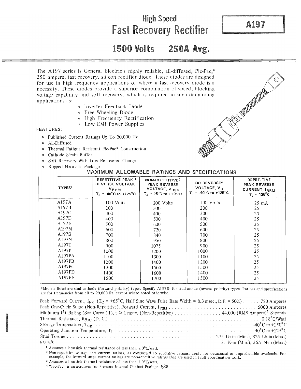
The
A197
250
ampere,
for use in high
necessity. These
voltage
applications
FEATURES:
..
Published Current Ratings Up To
..
All-Diffused
..
Thermal
..
Cathode Strain Buffer
..
Soft
..
Rugged Hermetic Package
series is
tast
General
recovery,
frequency
diodes
capability
and
as:
..
Inverter
..
Free
..
High
'"
Low
Fatigue Resistant Pic-Pac4 Construction
Recovery With Low Recovered Charge
MAXIMUM
TYPES*
A197A
A197B
A197C
A197D
A197E
A197M
A197S
A197N
A197T
A197P
A197PA
A197PB
A197PC
A197PD
A197PE
1
Electric's
sIlIcon
applications
provide a superior
soft
recovery,
Feedback
Wheeling
Frequency
EMI
Power
REPETITIVE
REVERSE
VRRM
= -40°C
T
J
100 Volts
200
300
400
500
600
700
800
900
1000
1100
1200
1300
1400
1500
highly
rectifier
which
Diode
Rectification
Supplies
20,000
ALLOWABLE RATINGS
PEAK
VOLTAGE
to
+125°C
Volts
reliable, all-diffused, Pic-Pac,4
diode.
or
where a fast recovery
Diode
Hz
I
These
combination
is
required in
NON·REPETITIVE2
PEAl<
REVERSE
VOLTAGE,
T
J =
25°C
to
200
Volts
300
400
500
600
720
840
950
1075
1200
1300
1400
1500
1600
1700
diodes
of
speed,
such
AND
VRSM
+125°C
are designed
diode
is
a
blocking
demanding
SPECIFICATIONS
to
3
R
+125°C
DC
REVERSE
VOLTAGE,V
T J = -40°C
100 Volts
200
300
400
500
600
700
800
900
1000
1100
1200
1300
1400
1500
REPETITIVE
PEAl<
REVERSE
CURRENT,IRRM
=
125°C
T
J
25
mA
25
25
25
25
25
25
25
25
25
25
25
25
25
25
I
"'Models listed are stud cathode (forward polarity) types. Specify A197R- for stud
are for frequencies from
Peak
Forward Current,
Peak One-Cycle Surge (Non-Repetitive),
Minimum
Thermal
Storage
Operating
Stud
NOTES:
1 Assumes a heatsink
2 Non-repetitive voltage and current ratings, as contrasted to repetitive ratings,
3 Assumes a heatsink thermal resistance
4 "Pic-Pac"
2
I
t Rating (See Curve
Resistance, R8JC (D.
Temperature,
Junction
Torque
example,
...................................................
the
is
50
to
20,000
Hz, except where noted otherwise.
IFM
(Tc
= +65°C,
11),
C.)
...................................................
Tstg
......................................................
Temperature,
thermal
forward surge current ratings are non-repetitive ratings
an
acronym
for Pressure Internal
TJ ................................................
resistance
Half
Sine
Wave
Forward
t
;;;,
1 msec. (Non-Repetitive)
of
less
of
less
than
2.0°C/watt.
than
l.O°C/watt.
Contact
Current, I
Package.
Pulse Base Width =
FSM
.......................•......
................
that
are used in fault
588
anode
(reverse polarity) types. Ratings and specifications
8.3
msec., D.F. = 50%)
apply
for occasional
coordination
44,000
275
Lb-in (Min.),
31 N-m (Min.), 36.7 N-m (Max.)
......
5000
(RMS Ampere)2 Seconds
-40°C to
-40°C
325
or
unpredictable overloads.
work.
720
Amperes
Amperes
0.18°C/Watt
+I50°C
to
+125°C
Lb-in (Max.)
For
Page 2
til
W
Q:
W
"-
::::
<I:
I
I-
z
W
Q:
Q:
::>
L>
Cl
Q:
~
Q:
~
gJ
@
Z
~
Z
~
til
~
10,000
1,000
100
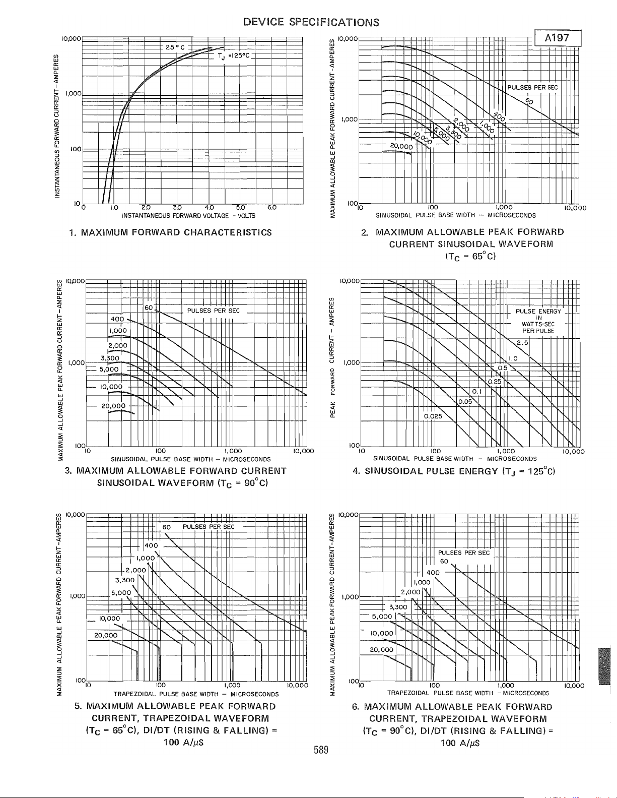
1.
MAXIMUM
1/
I
II
1.0
INSTANTANEOUS
25
.Q
..,,'P'
L~
2.0
FORWARD
3.0 4.0 5.0
FORWARD
DEVICE
° C
TJ '125°C
VOLTAGE -VOLTS
CHARACTERISTICS
SPECIFICATIONS
til
w
Q:
W
"-
::::
~
I-
Z
W
Q:
Q:
::>
u
Cl
Q:
~
Q:
~
<!
'"
w
"-
W
...J
ro
~
o
...J
...J
<I:
::;;
::>
::::
6.0
x
<I:
::::
10,000
1,000
-
-
-
-
I---
20,000
SINUSOIDAL PULSE
2.
MAXIMUM
CURRENT
..........
-
-
-
-
.....
~
~,<~~>,
/q~~Oo
100
ALLOWABLE
.......
""'"
.......
t?-
BASE
WIDTH -MICROSECONDS
SINUSOIDAL
(TC
= 65°C)
"
'-l!.o
/ 0
-<Cb
r-,0
1,000
PEAK
WAVEFORM
PULSES
PER
~O
'"
FORWARD
A197
SEC
i'-
10,000
~
IQ,oOO
Q:
w
"-
::::
<I:
I
I-
Z
w
Q:
0:
::>
u
Cl
0:
~
Q:
1,000
~
'"
<I:
W
"-
W
oj
~
o
...J
...J
<I:
::;;
::>
::;;
~
::::
3.
~
10,000
Q:
W
"-
::::
<I:
I
I-
Z
W
Q:
Q:
::>
u
Cl
~
~
1,000
'"
<I:
W
"-
W
...J
ro
~
g
...J
<I:
::::
::>
~
<I:
::::
j------
400
1,000
~
3,300
r-.
= 5,.000
-IO,~
-26~l
100
10
SINUSOIDAL PULSE BASE
MAXIMUM
f---
I-
20,000
10010
5.
MAXIMUM
CURRENT,
(Tc
ALLOWABLE
SINUSOIDAL
1,000
2,000
3
300
1\
,
,\
5,00~
10,000
I'
I'
......
.......
1'-
TRAPEZOIDAL
ALLOWABLE
= 65°C),
60
PULSES
"-
r--.
"
~
"'"
"'-
"'-
""
"'"
"
100
WAVEFORM
60
400
_\.
.'"
'"
WIDTH -MICROSECONDS
FORWARD
PULSES
\.
'\.
"-
'"
"
'\.
'"
I"
I~
100
PULSE
TRAPEZOIDAL
DI/DT
100
~
"
BASE
WIDTH -MICROSECONDS
PEAK
(RISING & FALLING)
AlpS
PER
SEC
~
1,000
CURRENT
(Tc
= 90°C)
PER
SEC
i'-
"'"
""
"""-
1,000
FORWARD
WAVEFORM
=
10,000
10,000
589
til
W
0:
W
"-
::::
«
I
I-
Z
w
0:
0:
::>
u
0
a:
;l:
'"
a:
0
U-
<I:
'"
w
"-
~
0:
W
"-
::;;
~
I-
Z
w
Q:
0:
::>
u
Cl
0:
~
0:
~
«
'"
w
"-
W
...J
ro
«
3:
o
...J
...J
«
::;;
::>
::;;
~
::::
10,000
1,000
100
10,000
1,000
6.
4.
10
~
r--
r--.
-
-
I-
SINUSOIDAL PULSE
SINUSOIDAL
2,000
3,300
5,000
.,
I
!-.....
10,000
20,000
MAXIMUM
CURRENT,
(TC = 90°C),
I'-
.......
1'
........
.......
r-,
TRAPEZOIDAL PULSE
"-
"'-
.......
"-
"-
~
~
0.Q2~
III
100
BASE
PULSE
PULSES
400
I'OOO~
!"-.
......."'"
100 1,000
ALLOWABLE
TRAPEZOIDAL
DIIDT
I'-.
['-.
"
"
"
0.05"
0.1
'\.
'\.
r-..,
'"
WIDTH
ENERGY
PER
60
"
I'-.
""
I"
-
.......
I'-.
'"
"""-
"
BASE
(RISING &
100 AlpS
1""
WIDTH -MICROSECONDS
PEAK
PULSE
"-
"
0.2
G
0.5
I'..
WATTS-SEC
PER
1.0 I'..
"'"
\
,
'"
~
1,000
- MICROSECONDS
(TJ = 125°C)
SEC
i'
~
'1
FORWARD
WAVEFORM
FALLING)
ENERGY
IN
PULSE
"
",
"'r-..,
=
'1'\
10,000
10,000
Page 3

A197
10,000
Ul
w
er
w
11.
::;
<1
,
I-
:2
w
er
er
::J
U
a
er
<1
:;:
er
f2
<1
'"
w
11.
1,000
-
-
-
0.0251'
100
10
7.
TRAPEZOIDAL
DIIDT
2.5
1.0,
0.5",
0.25",
0.1
=
0.05
"-
"-
'"
TRAPEZOIOAL PULSE BASE
100 1,000 10,000
""
PULSE
(RISING &
"
I'.
"-"
'"
'"
'"
""
"
WIDTH
ENERGY
FALLING)
DEVICE
PULSE
ENERGY
IN
WATTS-5EC
PER PULSE
"'"
"-
"-
"-
"
"
"
""
"'I'.
"
"
""
- MICROSECONDS
(TJ = 125°C)
= 100
A//lS
I'.
SPECI
FICATIONS
1,000
Ul
CD
::;
:3
§
~IOO
w
(!)
er
<1
:r:
u
a
w
er
w
1)
10
td
er
w
(J)
er
w
>
w
er
lil
er
lE
CI
I
II
8. RECOVERED CHARGE (T
(Maximum Recovered
If
maximum
request
....
~
REVERSE
A197
~
10
dildl
- AMPERES I MICROSECOND
recovered charge
__
X9, e.g.
A197BX9,
100
ChargE,!
group
I
.-/
V-
100
~
r\FM
erO
~
'I
REVERSE
di/dl
= 125°C)
J
Group
12
is
required,
A197RBX9,
Iit"
,......
RCW
12)
1,000
....!-1"
200
-IR
etc.
400
(REC)
1,000
d,/dl
r'A
--i\?-
IRM
~e;~,
j_
1.0
(~~~)
- - -
_f-
--
.I
o
1.0
REVERSE RECOVERED CHARGE -
9.
REVERSE
TYPICAL
RECOVERED
(di/dl)REC
.+-tB~
I '"I
I
I
I
/
,
_
L_
I
I
'~;"~ACTOR-
t B
tA
-I-"""
I
--
-
10
"s"
FACTOR
CHARGE
z _
"l("
a:
.... ~ Q
~
N
H I
100
OR
(REC)
P.
COULOMBS
VERSUS
(TJ = 125°C)
m
400,-----,-----,-------~--_,----,__,--,_,__"
~
300~----~-----~------t---~.----~_+--+_~~~
u
~
200r-----+-----~-------+---_4----~_+--+_~~~
~
0
80
60
[flOIOO~~~!~'§~~!1
oCt
x
50
40
m
:IE
0:
1000
;l:
,
u
UJ
U
Z
C3
UJ
a.
~
.J
<t
:IE
0:
~
l-
I-
z
UJ
iii
z
<t
0:
I-
1.0
o.
0.5
.0 I
.5
I
V-
.001
10.
.01
TRANSIENT
I'
......
0.1
TIME
THERMAL
JUNCTION-TO-CASE
1.0
IN
SECONDS
IMPEDANCE -
10
100
I
1.5
11. SUB-CYCLE SURGE
AND
J2
t
FOLLOWING
PULSE
RATINGS
RATED
590
3 4 5 6 7 B 9
WIDTH-MILLISECONDS
FORWARD
VERSUS PULSE
LOAD
CURRENT
TIME
CONDITIONS
10
Page 4

MODEL
AI97
FORWARD
POLARITY
AI97R
REVERSE
POLARITY
TERMINAL
1
ANODE
CATHODE
OUTLINE
TERMINAL
2 THREAD SIZE
CATHODE
MIODE
3/4
Uf\JF
DRAWING
S
-
16
- 2A
TABLE OF DIMENSIONS
DECIMAL INCHES METRIC MM
SYM.
A 1.450 1.550 36.8: 39.37
B
2.300 2.500 58.42 63.50
C
D
5.300 5.700
F
J .665 .755 16.89 19.18
K 322 333 8.17
L 437
M .325 .360 8.25
N .155
P 1.060 1.100 26.92 27.94
0 .660
T
1.240
V
NOTES:
Flexible
COJlper Lead.
One
Nut
and
Hardware
"T"
are
Angular
Dimension
Within
Qnental10n
is
3.
4.
Conversion Table
MIN.
MAX.
500
750
.797
2.5
.827 20.24 21.01
-
.170
.749 16.76 19.02
-
.156
1.250 31.49 31.75
One
Lockwasller
Steel, Cad Plated.
IS Area
of
Threilds
of
Seating
of
Terminals
MIN.
'.7C
134.62 144.78
11.99
-
Supplied
Unthreaded
Plane
IS
Undefmed.
With
PortIOn
MAX.
19.05
8.46
9.14
3.96
Each
-
-
Unlt.
Complete
NOTES
3
Material
Threads
A197
of
MOUNTING INSTRUCTIONS
Following these installation instructions will result
or less.
1.
Be
sure mounting surface
2. Mounting hole diameter should
and should be deburred.
3.
Use
Dow Corning's DC3, 4, 340 or 640 or
the heatsinlc
Use
only hardware furnished with each rectifier diode.
4.
5.
Tighten with a torque wrench, from nut side,
is
clean and flat within .001 inch/inch.
not
exceed the outside diameter
in
a rectifier diode-to-heatsinl< contact thermal resistance
of
the rectifier diode stud
GE
G322L or equivalent, on mounting surfaces that come in contact with
to
325 lb-in max.
by
of
O.OgO
more than 1/16 inch,
Cjwatt
591
Page 5

5.2
A197
Condensed Electrical and Thermal Characteristics and Ratings
RECTIFIERS
250
TO
275
AMPERES
JEDECTYPE
GETYPE
SPECIFICATIONS
(1
phase operation)
IFM(AV)
V
(Rep)
RM
IFM
(Surge)
2
1
t
T
J
Rmc
Max. average forward
Tc = (DC)
Max. repetitive peak reverse voltage (V)
Max. peak one cycle, non-recurrent
surge current
(1
phase operation) 50 Hz.
@ max. rated load conditions (A) 60 Hz.
Max. non-repetitive for 1.5 msec (A2sec)
Operating junction temperature range
Max. thermal resistance,
junction-to-case (DC/W)
Max. peak forward voltage drop @ rated
I
)
(1
V
FM
FCAV
phase operation)
@Tc = (DC)
QR(REC)
tIT
V
F
Reverse recovered charge @ rated T J
Reverse recovery time @ rated:rJ
Max. forward
(I)
voltage drop
for the current
range:
Transient thermal(2)
Rmc
resistance for
time: F
Package Outline No.
Maximum Stud Torque (In-Lbs/N-M)
Expanded Electrical Characterization, see page:
(DC)
(ILc)
(ILs)
IM1N(A)
IMAX(A)
A
B
C
D
TM1N(S)
TMAX(S)
G
250
\ 144 130
100-1500
6000
6500
70,000
-40
to 200
.18
1.3
144
-
- -
100
8000
.318
.0186 .007
2.62E-4 .0002
.022
.001
.01
.138
.33
128
325/36.72
N.A.
250
100-1400
-
4500
-
-40
to 200
.18
1.3
130
-
20
7000
.27
.03
.001
.01
.14
.33
128
325/36.72
N.A.
250 250 275
110
100-1500
4800
95
100-1500 100-1000
-
5000 7000
50,000 166,000 73,000
-40
to 125
.18
1.5
-40
to 175
.18 .18
1.7
-65
25 25 120
70
2.8
85
3.1
40 20 40
6000
-.94
.51
6000
- .145 .6
.29
.0009 .0007
-.06
-.03
.001 .001
.01 .01
.138 .138
.33
128
325(36.72 325/36.72
146
.33
128
325/36.72
148
120
4500
5000
to 190
l.35
-
-
4000
-.056
.0003
.03
.001
.01
.1
.2
128
N.A.
(I
JVoltage Drop Model: V F = A + B . LN(I) + C . I + DVI
(2JTransient Thermal Resistance Model:
I
RSJC
= F .
TO
113
 Loading...