

Page 1
The
150
A187
ampere,
series
is
General Electric's highly reliable, all-diffused, Pic-Pac,4
fast recovery, silicon rectifier diode. These diodes are designed
for use in high frequency applications
necessity. These diodes provide a
soft
voltage capability and
recovery, which
superior
applications as:
..
FEATURES:
..
Published
..
All-Diffused
..
Thermal
..
Cathode
..
Soft
Recovery
..
Rugged
..
Available
TYPES*
A187A
A187B
A187C
A187D
A187E
A187M
A187S
A187N
A187T
A187P
A187PA
A187PB
A187PC
A187PD
A187PE
Inverter
..
Free Wheeling Diode
..
High
..
Low EMl Power Supplies
Current
Fatigue Resistant Pic-Pac4 Construction
Strain
Hermetic
in
Buffer
With
3/8"
Ratings Up
Package
or
MAXIMUM
Feedback
Frequency
To
Low
Recovered Charge
1/2"
Stud
REPETITIVE
REVERSE
V
T J = -40°C
RRM
lOO
200
300
400
500
600
700
800
900
1000
1100
1200
1300
1400
1500
Rectification
20,000
ALLOWABLE
PEAK
VOLTAGE
to
+125°C
Volts
High
ec
or
where a fast recovery diode
combination
is
Diode
Hz
NON-REPETITIVE2
1
VOLTAGE,V
J =
T
e
of
speed, blocking
required in such demanding
RATINGS
PEAK
REVERSE
25°C
200
Volts
300
400
500
600
720
840
950
1075
1200
1300
1400
1500
1600
1700
to
AND
RSM
+125°C
er
DC
REVERSE3
VOLTAGE,V
= -40°C
T
J
100 Volts
200
300
400
500
600
700
800
900
1000
1100
1200
1300
1400
1500
A190
is
a
FICATIONS
R
to
+125°C
SEE
lN3735,
PEAl<
CURRENT,I
1 1
PAGE
REPETITIVE
REVERSE
=
25
25
25
25
25
25
25
25
25
25
25
25
25
25
25
125°C
mA
RRM
T
J
241
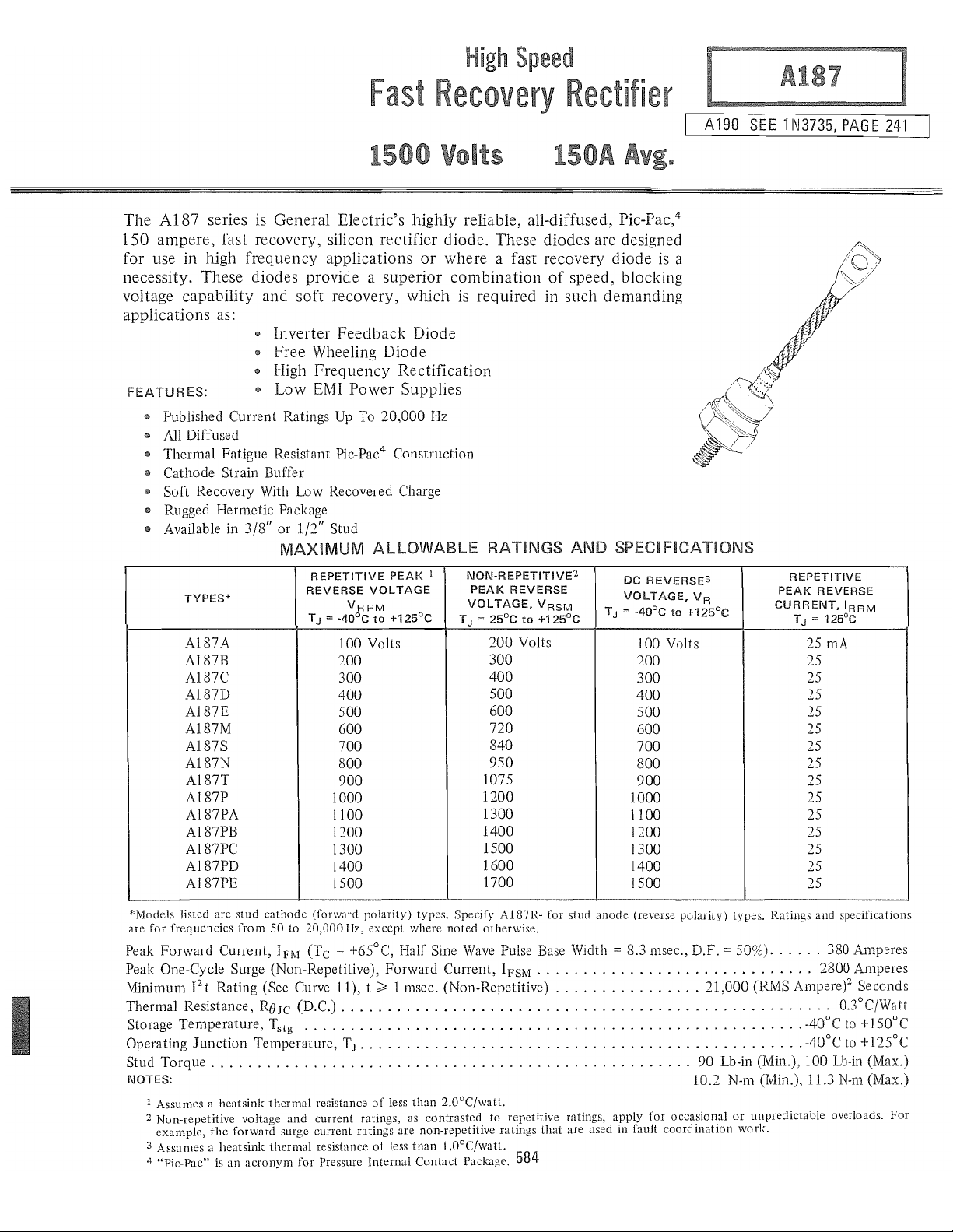
"'Models listed are
are for frequencies from 50 to 20,000 Hz, except where
Peak
Forwanl
Peak One-Cycle Surge (Non-Repetitive),
Minimum I
Thermal Resistance,
Storage
Operating
Stud
NOTES:
Temperature,
Torque
1 Assumes a heatsink
2 Non-repetitive voltage
example,
3 Assumes a
4 "Pic-Pac" is an
stud
cathode
Current,
2
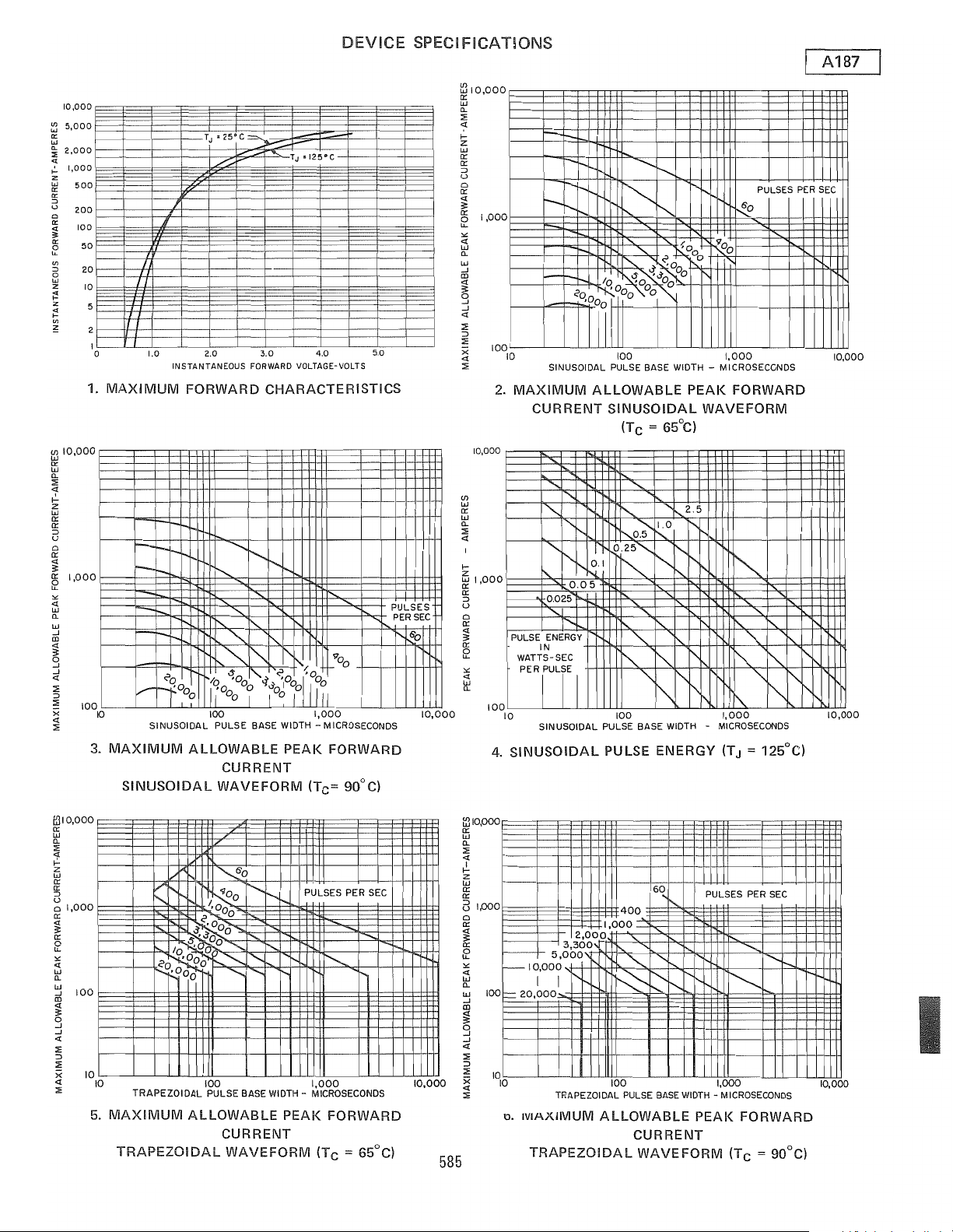
t Rating (See Curve
ReJc
Junction
Temperature,
....................................................
the
forward surge current ratings are non-repetitive ratings
heatsink
acronym
(forward polarity) types. Specify A187R- for stud
IFM
(Tc = +65°C,
II),
(D.C.)
.....................................................
Tstg
......................................................
T
J
thermal
thermal
resistance
and
current ratings, as contrasted to repetitive ratings, apply for occasional
resistance
for Pressme Internal Contact Package.
Hail' Sine Wave Pulse Base Width = 8.3 msec.,
Forward
t > 1 msec.
•.•.••••.••••••••••••..•....••••••••••••.•.••...
of
less
than
of
less
than
noted
otherwise.
Current,
(Non-Repetitive)
2.0oC/watt.
l.O°C/watl.
IFsM
584
anode
(reverse polarity) types. Ratings and specifications
D.F.
..............................
................
90
10.2 N-m (Min.), 11.3
that
are used in fault coordination work.
= 50%)
......
21,000
(RMS
Lb-in (Min.),
or
unpredictable overloads.
380 Amperes
2800 Amperes
Ampere)2
O.3°C/Watt
-40°C
to
-40°C to
100
Lb-in (Max.)
N-m
Seconds
+150°C
+125°C
(Max.)
For
Page 2
10,000
~
51000
0:
W
~
2,000
>-
1,000
"
z
Ii!
500
0:
"
u
200
Cl
0:
~
100
gs
50
"-
20
'"
o
"
w
Z
;0
z
«
>-
'"
"
1il10,000
0:
w
0-
::E
<t
.:-
Z
w
0:
0:
::J
U
o
0:
~
~
1,000
ox:
<t
W
0-
W
-'
aJ
~
-'
-'
<t
::E
::J
::E
100
x
<t
:;;
10
5
ITT
I
a
1.
MAXIMUM
10
3.
MAXIMUM
SINUSOIDAL
DEVICE
•
T
25·
C
=---
.....
J
.....-::
/
:.-r-
TJ
B125'"C
"
1.0
I--
1-'
l-
I-
r----
i-
V
11
SINUSOIDAL PULSE BASE WIDTH - MICROSECONDS
2.0
INSTANTANEOUS
FORWARD
l-
f'--...
I"-....
_"'"
/,
0
Ilqo
°0
11°011
100
ALLOWABLE
CURRENT
WAVEFORM
3.0
FORWARD VOLTAGE-VOLTS
CHARACTERISTICS
'-..,
\'-.
1'-r-.
"
1"...
'J'.
r'-.,
~
1')'-.
"'"
10
i"..
00
~o
of".,
00
I
00
/ 0
:{OO
I (
1
1,000
PEAK
(TC==
4.0
110
III
FORWARD
90°C)
SPECIFICAT!ONS
~
w
0-
:;:
«
>-
z
w
0:
0:
::J
U
o
0:
«
3:
~
'"
<t
W
0-
W
-'
aJ
<t
~
-'
«
:;:
::J
:;:
10,000
><
«
:;;
(/)
W
0:
W
0-
:;:
«
>-
z
~
0:
::J
U
o
0:
0:
5.0
PULSES
PER
SEC
1'6'0
10,000
10,000
1,000
~
::2
'"
«
i'C
1,000
100
10
2.
MAXIMUM
i----'
PULSE
WATTS-SEC
PERjUT
0
10
10
4.
SINUSOIDAL
I--
:-
-..
\'-.
'"
r~
I'...
.......
1"-
~O
r--
'-"'1"'-
i"-
"'"
110
I"'-
t--b
-
20
'Ill
SINUSOIDAL PULSE BASE WIDTH - MICROSECONDS
"
~
is
10
'0
~OOO
100
<?
<{".,'OOO
00
00
~O
ALLOWABLE
CURRENT
"'-
"'"
........
1'-,.....
/'...
0.025
1"1-
"
ENERGY
IN
"
"1'
0.05
I
N.
0.1
SINUSOIDAL
(T c
==
65°C)
"'-
.....
~
1.0
~O?-
r-...
0.25"-
~
~
"
.""-
""-
I"-
1'-
~
r"
/'-,
1'0,
I"
~
SINUSOIDAL PULSE BASE WIDTH -
100
PULSE
ENERGY
0
0
1,000
PEAK
FORWARD
WAVEFORM
2.5
"-
1'1'
~
l"\
I'
~
I"f'
t-."
1,000
MICROSECONDS
(TJ
"
==
PULSES
r'-.,
~
""-
I"-
125°C)
i'-
PER
i'
1'.1'
A187
SEC
10,000
10,000
ffjIO,OOO
0:
w
0-
::E
~
z
W
0:
~
U
01,000
0:
~
0:
f2
'"
«
w
0-
'j
100
aJ
~
o
-'
-'
«
:;;
::J
::E
;(
~
10
10
TRAPEZOIDAL
5.
MAXIMUM
TRAPEZOIDAL
~o
/r-.
"
~O
10'
<:0
,OOd'r-....~
I"r=...ooo
,
'\10
0
1'000
<:'0
0
,
0"'"
0
"-
I"
......
...........
100
PULSE BASE WIDTH - MICROSECONDS
ALLOWABLE
CURRENT
WAVEFORM
PULSES PER
"-
~
1,000
PEAK
SEC
I'-...
FORWARD
(Tc
==
65°C)
10,000
585
1il10,000
0:
w
0-
:;:
<t
~
Z
W
0:
0:
i:3
IPOO
o
0:
~
)----
5?
r--IO,OOO
'"
«
w
0-
100
w
=
-'
aJ
~
9
-'
<t
::E
::J
:;:
10
;(
10
«
:;;
o. IVIAXiMUM
2,000
3,300
I-
5,000
I
I
20,000
TRAPEZOIDAL PULSE
ALLOWABLE
TRAPEZOIDAL
6~
400
1,000
~
"
I"-
b:::--
1'-.
100 1,000
BASE
PULSES PER
"-
r--
I'--
WIDTH -MICROSECONDS
PEAK
CURRENT
WAVEFORM
SEC
"-
.......
"'"
~
FORWARD
(TC
==
90°Cl
10,000
Page 3

If)
W
0::
W
a.
:;:
<t
I
I-
Z
W
0::
0::
=>
U
0
0::
~
0::
It
<t
'"
w
a.
«
...
......
II!l
...
II:
0
t-
o
~
:
(/)
A187
1,000
100
10
10
0.3
"-
."
PULSE ENERGY
IN
WATTS-SEC
PER
PULSE
i'
'-
""-
"-
'"
"-
~.o25
~.I
"-~oi
""
I"-
"-
di/dl
100
PULSE ENERGY,
FALLING)
(TJ = 125°C)
=
TRAPEZOIDAL PULSE BASE WIDTH - MICROSECONDS
7.
TRAPEZOIDAL
(RISING &
.......
~.5
""-
1.0
0.25
~
I'"
~
""
"-
l'-.
'"
~
['.
'"
1,000
DI/DT
100
AIMS
I
+-+-+-t--HH-I
DEVICE
0
"-
"-
i'
"'t'-
l'
SPECIFICATIONS
600
Vl
III
:i!
9
200
5
u
:t.
,
100
w
IE
..
50
0
c
ll!
20
~
l:!
10
~
>
W
.....
0:
U
2
W
~
Il:
I
~
~
I
W
U
Z
C!i
W
Il.
~
;;t
:i!
Il:
W
J:
... .
...
z
w
iii
z
..
Il:
...
0
8.
If
request
1.0
.5
I
o.
05
1/
V-
10,000
.....
50
r:-
.......
~
r-
r--
........
10
i/dl
20
(AMPERES IMICROSECONDI
~
~FM
::>
0
I
REVERSE
50
41'.
~
I..<:
~I-""
5
REVERSE d
RECOVERED CHARGE (TJ = 125°C)
(Maximum
maximum
A187_
Recovered
recovered charge
X9, e.g.
A187BX9,
Charge
group
Group
12
is
required,
A187RBX9,
vrV
V
V
IFM=400A
10
A
R!:fi
di/dl
LRM
100
12)
etc.
A-
-
(RECI
I
.0
o.
:.'=0---L-----''---'--..J........L..J.--'-"''"''0!c---..J.......-.L---'-......L.--'-..L...l~1
REVERSE RECOVERED CHARGE Q
9.
TYPICAL
"S"
FACTOR VERSUS REVERSE
RECOVERED CHARGE (TJ
(REC)JL COULOMBS
R
= 125°C)
90
~g
70
1r0
~;
50
~'"
~~
30
-
N
H
~~
20
- l
i
10
...
z
71-
W
0
Il:
0
5
ll:
0
::J :
4
u
w
Vl
3
(!)
w
ll:
Il:
::J W
2
'"
Il.
:IE
..
..
"
W
Q.
11. SUB-CYCLE SURGE FORWARD CURRENT
AND
-l-
1.5
2
1
t RATINGS VERSUS PULSE
00
----.
PULSE
FOLLOWING RATED
I
.001
10.
TRANSIENT
.
-~.-
r--
-
WIDTH-MILLISECONDS
4 6 7 8 9
LOAD
CONDITIONS
.01
0.1
TIME IN SECONDS
THERMAL
JUNCTION-TO-CASE
l-
-
10
TIME
1.0
10
IMPEDANCE -
100
586
Page 4

A187
MODEL
M07
FORWAno
POLARITY
AlaTR
REVERSE
POLARITY
TERMINAL
CATHODL:
TERMINAL
1
ANODE CATHODE
THREAD
2
ANODE UNF -
SIZE
J/8 -24
5
THREAD
LENGTH DIAMETER
.640 .373
-.610 IN.
16.26 9.47
2A
15.49 MM
MOUNTING
OUTLINE
F a
RELIEF
-:344
BT4
DRAWING
DECIMAL
IN.
MM
SYM.
NOTES:
1.
2.
3.
4.
S.
6.
MIN.
A 1.020 1.140 25.9D
.390
B
1.570 1.750
C
4.750
0
,520
J
K .270 .291 6.85
L
.320
.280
M
N .070
.840
P
.920
R
Nut
Dimension
Dimension
Within
Orientation
-
1.052
and
is
Steel-Cad Plated.
2.5
T
V
Flexible Copper Lead,
One
Hardware
"R"
"T"
are
Angular
Approximate
INSTRUCTIONS
TABLE
OF
DIMENSIONS
C ve T bl
on
r5lon a e
INCHES METRIC MM
MAX.
.500
5.150
.625 13.20
-
.320
.110
.910
-
.060
1.063
9/32
Inch
One
Lackwasher
is
Diameter
is
Area of
Threads
of
Weight: 105 Grams.
Supplied
of
Effective
Unthreaded
of
Seating Plane.
Terminals
Nominal
MIN.
9.90 12.70
39.87
120.65
21.33
23.36 -
26.72
is
MAX.
28.96
44.45
130.81
15.88
7.39
8.12
7.11
1.77 2.79
-
Undefined.
-
8.13
23.11
1.52 4
27.00
Diameter.
With
Each
Seating
Area.
Portion. Complete Thremjs
Unit.
NOTES
Material
3
of
Following these installation instructions will result in a rectifier diode-to-heatsink contact thermal resistance
or less.
1.
Be
sure mounting surface
2. Mounting hole diameter should
is
clean and flat within .001 inch/inch.
not
exceed the outside diameter
of
the rectifier diode stud by more than 1/16 inch,
and should be deburred.
Use
3.
Dow Coming's DC3, 4, 340 or 640 or GE G3221 or equivalent, on mounting surfaces
that
come
the heatsink.
Use
4.
5. Tighten with a torque wrench, from nut side,
only hardware furnished with each rectifier diode.
to
100 lb-in max.
of
0.10 C/watt
in
contact with
587
Page 5

SPECIFICATIONS
A187
Max.
average forward
Tc
JFMIAV)
(Rep)
V
RM
IFM
(Surge)
J2
t
T
J
ReJc
V
FM
QR(REC)
tIT
V
F
ReJc
Package
Maximum
Max
Mounting Force
Expanded Electrical Characterization, see page:
= (DC)
Max. repetitive
Max.
peak
surge current
@ max. rated load conditions (A)
Max. non-repetitive
Operation
Max. thermal resistance,
junction-to-case (DC/W)
Max.
I
FIAV
@Tc
Reverse recovered charge @ 'fated T
Reverse recovery time @ rated T,
Max. forward (1)
voltage drop
for the current
range:
Transient thermal(2)
resistance
time:
Outline No.
Stud Torque (In-Lbs/N-M)
one cycle, non-recurrent
(1
junction
peak forward voltage drop @ rated
)
(1
phase operation)
= (DC)
for
(Lbs'/Kn)
(1
phase operation)
peak
reverse voltage (V)
phase operation)
for
1.5 msec (A2sec)
temperature range (DC)
150
50
Hz.
60
Hz.
(p,c)
J
(p,s)
IM1N(A)
IMAX(A)
A
B
C
D
TM1N(S)
TMAX(S)
F
G
TO
RECTIFIERS
225
AMPERES
160 150
125
100-1200 100-1500
-
2000
6000
-55
to 190
.3
1.3 1.3
125 143
-
-
10
2000
.3905 .53
.0l37
.0008
.0343
.001 .001
.01
.21 .21
.34
128 127.1
-
- -
N.A. N.A.
143
3200
3400
26000
-40
to 200
.3
-
-
10
6000
.079
8.85E-4
8.1E-3
-
.01
.34
100/11.3
109.1
150
65
100-1500
2600
2800
23000
-40to
125
.3 .35 .095
1.7
25 108
50
2.3
10
6000
.363
.151
7.04E-4
4.12E-3
.001 .001
.01
.21
.34 .49
127.1 323 109.1
100/11.3
-
N.A.
150
108
800
2800
3000
24000
-40
to 175
1.3
-
-
100
25000
-1.4
0.727
.0022
-1.31
.01
.261 :072
-
-
151
600-1500
-40
225
80
3350
3500
22000
to 125
2.7
65
15
1.5
200
5000
.038
.234
5.95E-4
.025
.001
.01
.24
800/3.56
-
162
Drop
(l)Voltage
(2)Transient Thermal Resistance Model:
Model: V F = A + B . LN(I) + C . I +
ReJc
DVI
= F
112
 Loading...