

Page 1
st
ctifier
Its
The
Al77
100
ampere, fast recovery, silicon rectifier diode. These diodes are designed
for use in high frequency applications
necessity. These diodes provide a superior combination
voltage capability and soft recovery, which
applications as:
FEATURES:
..
..
..
..
..
.. Rugged Hermetic
.,
series
is
General Electric's highly reliable, all-diffused, Pic-Pac,4
" Inverter Feedback Diode
..
Free Wheeling Diode
Freq uency Rectification
.,
Low
EM!
Power Supplies
Published Current Ratings
Up
To
All-Diffused
Thermal
Fatigue Resistant Pic-Pac4 Comtruction
Cathode Strain Buffer
Soft
Recovery With Low Recovered Charge
Available in
3/8/1
or
Stud
MAXIMUM
!
REPETITIVE
TYPES"
Al77A
Al77B
Al77C
Al77D
Al77E
A177M
Al77S
Al77N
Al77T
Al77P
Al77PA
Al77PB
Al77PC
A177PD
A177PE
REVERSE
i T
J
I
VOLTAGE
V
RRM
-40°C
to
100
Volts
200
300
400
500
600
700
800
900
1000
1100
1200
1300
1400
1500 1700
or
where a fast recovery diode
is
20,000
Hz
ALLOWABLE
PEAK
+125°C
NON-REPETITIVE2
1
VOLTAGE,VRSM
T
J
of
speed, blocking
required in such demanding
PEAK
REVERSE
=
25°
200
300
400
500
600
720
840
950
1075
1200
1300
1400
1500
1600
to
+125°C
Volts
T J =
is
a
SPECI FICATIONS
to
3
V
R
+125°C
DC
REVERse
VOLTAGE,
-40°C
100 Volts
200
300
400
500
600
700
800
900
1000
1100
1200
1300
1400
1500
1
REPETITIVE
PEAK
REVERSE
CURRENT,IRRM
T
125°C
J
20mA
20
20
20
20
20
20
20
20
20
20
20
20
20
20
*Models listed
are
for
Peak
Forward
are
frequencies
Current,
stud
from
cathode
50
to
IFM
(forward poJarity)
20,000
Hz,
except
(Ie
+65°C,
Peak One-Cycle Surge (Non-Repetitive),
Minimum
Thermal
Storage
Operating
Stud
NOTES:
1 Assumes a
2 Non-repetitive voltage and
3 Assumes a
4 "Pic-Pac"
12
Resistance,
Temperature,
Junction
Torque
example,
t Rating Curve 11), t
ReJc
(D.C.) . . . . . . . . . . . . . . . . . . . . . . . . . . . . . . . . . . . . . . . . . . . . . . . . .
. . . . . . . . . . . . . . . . . .
....................................................
heatsink
the
heatsink
is
lhermal
forward surge
thermal
an
acronym
resistance
current
ratings, as
current
r;lUngs are
resistance
for Pressure Internal
types.
Specify
where
noted
otherwise.
Half
Sine "lave Pulse Base Width =
Current,
;;;,
1 msec. (Non-Repetitive)
. . . . . . . . . . .
of
less
of
Jess
I
FSM
than
2.0DC/wa
contrasted
non-repetitive
than
l.ODC/walt.
Contact
Package.
•••••..•••...•....•.••..••••••••••••
..
tt.
to
Al
77
R- for stud
................
.............................
..
...........................
repetilive
ratings
that
are
577
anode
apply
in
(reverse
83
polarity)
msec., D.F. 50%)
13,500
90
10.2 N-m (Min.), 11.3 N·m (Max.)
for
occ,!sionul
fault
coordination
types. Ratings
(RIVIS
......
and
specifications
280
2500
..
. 0.4°C/WaH
0
.
_40
C to + 150° C
ru!.ljJC;lv~
Amperes
Seconds
to + 125°C
Lb-in (Min.), 100 Lb-in (Max.)
or
unpredictable
work.
overloads.
For
Page 2
A177
FICATIOf\lS
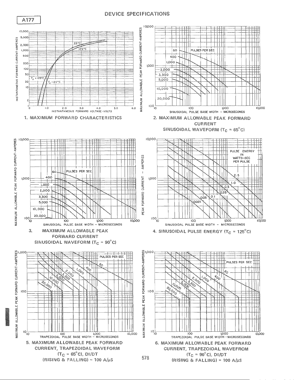
1.
MAXIMUM
10,000
I
100
L-2_0..:..,O-,0_0-""""""---Ll-L
10
SINUSOIDAL PULSE BASE
3,
MAXIMUM
SIf\lUSOIDAL
FORWARD
100
ALLOWABLE
FORWARD
WAVEFORM
CHARACTER
IPOQ
WIDTH
- MICROSECONDS
PEAl<
CURRENT
(Tc
STICS
2.
(/)
w
a:;
w
CL
::;:
«
~
1.000
u
o
a:;
5!
a:;
o
II
..
«
'"
w
CL
4.
SINUSOIDAL PULSE
MAXiMUM
100
BASE
ALLOWABLE
WIDTH
PEAl<
FORWARD
CURRENT
SiNUSOIDAL
WAVEFORM
~~~1Inl~~
SINUSOIDAL PULSE BASE WIDTH
SINUSOIDAL
100
PULSE
ENERGY
5.
MAXIMUM
CURRENT,
ALLOWABLE
TRAPEZOIDAL
(TC:=
65°C),
(RISING & FALLING)
PEAl<
FORWARD
WAVEFORM
DI/DT
100
6.
MAXIMUM
CURRENT,
TRAPEZOIDAL PULSE BASE WIOTH
100
ALLOWABLE
~OOO
PEAl< FORWARD
TRAPEZOIDAL
(T
""
90°C),
DI/DT
(RISiNG &
C
FALLING)
MICROSECONOS
WAVEFROM
100
AlpS
Page 3

U)
W
0::
W
a.
:l:
<t
I
I-
Z
w
0::
0::
:::>
u
0
0::
~
0::
f2
<{
'"
w
a.
<t
-
......
III
.::
a:
0
I-
u
<t
u..
-U)
1,000
100
0.3
PULSE ENERGY
WATTS-SEC
10
10
7.
DI/DT
DEViCE
'1:",2.5
~O
'"
0.25
~'"
1"'-,
"'-
""
i'-.
"'"
1,000
=
100
PER
"-
I'-
IN
PULSE
"'-
'"
~
'"
0.025
""~
'"
1"-0.1
'"
l'
r"
~05
"-
TRAPEZOIDAL PULSE BASE WIDTH - MICROSECONDS
TRAPEZOIDAL
100
(RISING &
PULSE
FALLING)
ENERGY
"'-
"'-
""
"'-
1"'-
""
"'-
I'-
AlpS
SPECI FICATIOI'-JS
<Jl
CD
600
:E
o
...J
:::>
o
u
200
;'-
w
a:
"'
100
J:
"
U
o
50
w
a:
w
i)
20
u
w
a:
10,000
w
a:
10
<Jl
w
>
w
a:
"
u
w
a:
a:
o
A
".
........
2
I
1.0
8.
(Maximum
If
maximum
request
1.0
f-
.5
,
w
u
z
o
"
w
n.
:E
...J
:E
"
a:
w
J:
....
....
z
w
iii
z
0:
"
....
.05
I
I
f-
I
"./
I
I
V
~
REVERSE
di/dl-AMPERES/MICROSECONO
I--""
,-
I-
50
A
t-
~
r\FM
0:0
3
RCfi
I
REVERSE
di/dl
10
20
50
RECOVERED CHARGE (TJ = 125°C)
A177_
Recovered
recovered
X9, e.g.
Charge
charge
A177BX9,
group
Group
12)
12
is
required,
A177RBX9,
I~
l-
.
V
,
I
A177
r'FM'=
200A-
IRM
IREClr--
I
100
etc.
I
=
I--
1=
t=
~
I
200
-
O.
\.Lo-----.J----.l-~~.L.J.....Ll-c!IOo----~-"----...L-...L....L.Ll.~IOO
REVERSE RECOVERED CHARGE
9.
TYPICAL
"S"
FACTOR VERSUS REVERSE
RECOVERED CHARGE
OR
(REC)J.L
(TJ
COULOMBS
= 125°C)
I .0
.001
10.
TRANSIENT
.01
0.1 1.0
TIME
IN
THERMAL
SECONDS
IMPEDANCE -
JUNCTION-TO-CASE
-
F--
r--
-
1.5
I
1.0
11. SUB-CYCLE SURGE FORWARD
AND
2
1
FOLLOWING
t
RATING
PULSE
WIDTH-MILLISECONDS
VERSUS PULSE
RATED
579
4
LOAD
CONDITIONS
l-
t-
5
7 8 9
CURRENT
TIME
r-
I--
10
II
10
100
Page 4

A177
OUTLINE
MOUNTiNG
DRAWING
NOTES:
1.
Fle)uble
Copper
2.
One Nut
imd
Dimension
DImensIOn
Within
One
is
2.5
WeiGht: 105
Hardware
3.
"R"
,:1,
"T"
'!i
Angular Orienttltion
6,
Apprnximnw
INSTRUCTIONS
TABLE
OF
LeJti,
3116
LocKWn:;her
is
Dinmeter
is
Area
of
Threads
of
Seating Plane,
of
Terminals Undefined.
Grams,
DIMENSIONS
Table
Inch f'Jominal Diameter.
Supplied
With Each Unit, Material
of
Effeaive
S<:ilting
Un
threaded
Panlan.
Area.
Complete
NOTES
Threads
Following these installation instructions will result in a rectifier diode-to-heatsink contact thermal resistance
or
less.
I.
Be
sure mounting surface
2.
Mounting hole diameter should
is
clean and
nat
within .001 inch/inch.
not
exceed the outside diameter
of
the rectifier diode stud
by
more than 1/16 inch,
and should be deburred.
Use
3.
Dow Coming's DC3, 4, 340
or
640
or
GE
G322L or equivalent, on mounting surfaces that come
the heatsink.
4.
Use
only hardware furnished with each rectifier diode.
5. Tighten with a torque wrench, from nut side, to
100 Ib·in max.
of
of
0.10°C/watt
in
contact with
I
580
Page 5

5.2
A177
Condensed Electrical and Thermal Characteristics and Ratings
~
~!
~
. . , 127.1
~
JEDECTYPE
GETYPE
SPECIFICATIONS
IFM(AV)
V
(Rep)
RM
IFM
(Surge)
e
t Max. non-repetitive for 1.5 msec (A2sec)
T
J
ReJc
V
FM
QR(REC)
trr
V
F
ReJc
Package Outline No.
Maximum
Expanded Electrical Characterization, see page:
Stud Torque (In-Lbs/N-M)
~.~
... ~ ..
".
20
Max. average forward
Tc
= (DC)
Max. repetitive peak reverse voltage (V)
Max. peak one cycle, non-recurrent
surge current
@ max. rated load conditions (A) 60 Hz.
Operation junction temperature range
Max. thermal resistance,
junction-to-case
Max. peak forward voltage drop @ rated
IF(AV)
@
Tc
Reverse recovered charge @ rated T
Reverse recovery time @ rated,T
Max. forward
voltage drop
for the current
range:
Transient thermal(2)
resistance for
time:
(1
(1
phase operation)
= (DC)
(1
phase operation)
phase operation) 50 Hz.
(DC/W)
(ILS)
J
(I)
IM1N(A)
IMAX(A)
A
B
C
D
TM1N(S)
T
G
(DC)
(ILC)
J
MAX(S)
F
RECTIFIERS
TO
100
AMPERES
50-600 50-1000
-
65
TYPICAL
TYPICAL
20
110
270 360
300
100 500
to
1.5
1.0
25
- -
-
.2
200
.3S
.0352
.00S2
.0559 .1434
-
- -
-
-
126
-
N.A.
175
25
75
400
-40
1.0
1.0
0.5
SOO
.6702
-.0094
-.OOOS
30/3.39
N.A.
to
75
.S
-
-
-
123
125
100
130
200-1200
1440 2250
1600
4000
-40
to 200
.4
1.4
25
-
-
2 1 3
2000
.42S3
-.0099
.0002 .0011 .0007
-0553
.001 .001 .001
.01 .01
.4
.3
127.1 127.1 127.1
100/11.3
N.A.
100
130
100-1500
2500
5500
-40
to 200
.4 .4
1.3 1.3
130 25
100-1500
-40
-
-
1000 3000
.4290 .4405
.100S .1163
-.OOOS
.4 .4
.3
100/11.3
N.A.
100
65
2250
2500
15000
to
125
50
2.3
.0172
.01
.3
100/11.3
N.A.
(I
)Voltage Drop Model: V F = A + B . LN(I) +
(2)Transient Thermal Resistance Model:
/
ReJc
CI + D.JI
= F .
to
111
 Loading...