


Variable Speed Drive
Programming and Software Manual


Variable Speed Drive
Programming and Software Manual
Edition: June 2016
SD50MTSW01EI Rev. E

SD500
POWER ELECTRONICS
2

POWER ELECTRONICS
SD500
3
Edition June 2016
This publication could present technical imprecision or misprints. The information here included will be
periodically modified and updated, and all those modifications will be incorporated in later editions.
To consult the most updated information of this product you might access through our website
www.power-electronics.com where the latest version of this manual can be downloaded.
WARNING
This symbol means improper operation may results in serious personal
injury or death.
CAUTION
Identifies shock hazards under certain conditions. Particular attention should
be given because dangerous voltage may be present. Maintenance
operation should be done by qualified personnel
Identifies potential hazards under certain conditions. Read the message and
follow the instructions carefully.
Identifies shock hazards under certain conditions. Particular attention should
be given because dangerous voltage may be present.
SAFETY SYMBOLS
Always follow safety instructions to prevent accidents and potential hazards from occurring.

SD500
POWER ELECTRONICS
4
Revisions
Date Revision Description
25 / 01 / 2011 A First Edition. Version SW 1.0
28 / 02 / 2011 B SW 1.1 Update
24 / 05 / 2011 C SW 1.2 Update
20 / 05 / 2013 D SW 2.0 Update
07 / 06 / 2016 E SW 2.3 Update
The equipment and technical documentation is updated periodically. Power Electronics reserves the right to modify totally or partially the
content within the present manual without notification.

POWER ELECTRONICS
SD500
INDEX
5
INDEX
SAFETY INSTRUCTIONS ........................................................................................................... 8
1. DISPLAY AND CONTROL KEYPAD UNIT .......................................................................... 12
1.1. Keypad Unit Description ............................................................................................. 12
2. STATUS MESSAGES .......................................................................................................... 15
2.1. Status Messages List ................................................................................................. 15
3. STATUS AND VISUALIZATION SCREENS ........................................................................ 16
3.1. Screens SV.1 – Motor Visualization ........................................................................... 16
3.2. Screens SV.2 – Drive Visualization ............................................................................ 17
3.3. Screens SV.3 – External Visualization ....................................................................... 17
3.4. Screens SV.4 – Internal Visualization ........................................................................ 17
3.5. Screens SV.5 – PID Visualization .............................................................................. 17
3.6. Screens SV.8 – Pump Macro Visualization ................................................................ 18
4. PROGRAMMING PARAMETER DESCRIPTION ................................................................. 19
4.1. Group 1 – G1: Options Menu ..................................................................................... 19
4.2. Group 2 – G2: Nameplate .......................................................................................... 21
4.3. Group 3 – G3: References ......................................................................................... 22
4.4. Group 4 – G4: Inputs .................................................................................................. 23
4.5. Group 5 – G5: Acceleration and Deceleration Ramps ............................................... 27
4.6. Group 6 – G6: PID Control ......................................................................................... 29
4.7. Group 7 – G7: Start / Stop Mode Configuration ......................................................... 30
4.8. Group 8 – G8: Outputs ............................................................................................... 33
4.9. Group 9 – G9: Comparators ....................................................................................... 36
4.10. Group 10 – G10: Limits .............................................................................................. 37
4.11. Group 11 – G11: Protections ..................................................................................... 39
4.12. Group 12 – G12: Auto Reset ...................................................................................... 42
4.13. Group 13 – G13: Fault History ................................................................................... 42
4.14. Group 14 – G14: Multi-references .............................................................................. 44
4.15. Group 15 – G15: Inch Speeds ................................................................................... 45
4.16. Group 16 – G16: Skip Frequencies ............................................................................ 45
4.17. Group 17 – G17: External Brake ................................................................................ 46
4.18. Group 18 – G18: ENCODER ..................................................................................... 46
4.19. Group 19 – G19: Fine Tuning .................................................................................... 47
4.20. Group 20 – G20: Communication Buses .................................................................... 50
4.21. Group 25 – G21: Pump Control ................................................................................. 51
5. MODBUS COMMUNICATION .............................................................................................. 55
5.1. Introduction……………………………………………………………………………………. 55
5.2. Specifications…………… ........................................................................................... 55
5.3. Installation………….. .................................................................................................. 56
5.4. RS485 Modbus Communication Protocol .................................................................. 58
5.5. Address List ..................................................................................................... 58
6. FAULT MESSAGES. DESCRIPTION AND ACTIONS ........................................................ 71
6.1. Description of Fault List .............................................................................................. 71
6.2. Procedure for Fault Solutions ..................................................................................... 72
7. COMMONLY USED CONFIGURATIONS ............................................................................ 75
7.1. Start / Stop Commands and Speed Reference by Keypad ........................................ 75
7.2. Start / Stop Commands by Terminals and Speed Reference by
7.3. Start / Stop Commands by Terminals and Speed Reference by
7.4. Start / Stop Commands by Terminals and Seven Speed References
7.5. Control of the Main Pump 1 and Auxiliary Pump 2, Seven References
8. CONFIGURATION REGISTER ............................................................................................ 86
Analogue Input . ………………………………………………………………………… 75
Buttons……………………………………………………………………………………….. 78
and 15 Selectable by Digital Inputs ............................................................................ 80
by Screen (Underload) ............................................................................................... 83

SD500
POWER ELECTRONICS
6
SAFETY INSTRUCTIONS
Do not remove the cover while the power is applied or the unit is in operation.
Otherwise electric shock could occur.
Do not run the drive with the front cover removed.
Otherwise you may get an electric shock due to the high voltage terminals or exposure of charged
capacitors.
Do not remove the cover except for periodic inspections or wiring, even if the input power is not
applied. Otherwise you may access the charged circuits and get an electric shock.
Wiring and periodic inspections should be performed at least 10 minutes after disconnecting the
input power and after checking the DC Link voltage is discharged with a meter (below 30VDC).
Otherwise you may get an electric shock.
Operate the switches with dry hands.
Otherwise you may get an electric shock.
Do not use cables with damaged insulation.
Otherwise you may get an electric shock.
Do not subject the cables to abrasions, excessive stress, heavy loads or pinching.
Otherwise, you may get an electric shock.
SAFETY INSTRUCTIONS
IMPORTANT!
Read this manual carefully to maximise the performance of this product and to ensure its safe
use.
In this manual, safety messages are classified as follows:
WARNING

POWER ELECTRONICS
SD500
SAFETY INSTRUCTIONS
7
Install the drive on a non-flammable surface. Do not place flammable material nearby.
Otherwise fire could occur.
Disconnect the input power if the drive gets damaged.
Otherwise it could result in a secondary accident or fire.
After the input power is applied or removed, the drive will remain hot for a couple of minutes.
Touching hot parts may result in skin burns.
Do not apply power to a damaged drive or to a drive with parts missing even if the installation is
complete.
Otherwise you may get an electric shock.
Do not allow lint, paper, wood chips, dust, metallic chips or other foreign matter into the drive.
Otherwise fire or accident could occur.
RECEPTION
The SD500 is carefully tested and perfectly packed before leaving the factory.
In the even of transport damage, please ensure that you notify the transport agency and POWER
ELECTRONICS: 902 40 20 70 (International +34 96 136 65 57) or your nearest agent, within
24hrs from receipt of the goods.
UNPACKING
Make sure model and serial number of the variable speed drive are the same on the box, delivery
note and unit.
Each variable speed drive is supplied with a SD500 technical manual.
RECYCLING
Packing of the equipments should be recycled. For this, it is necessary to separate different
materials included (plastic, paper, cardboard, wood, ...) and deposit them on proper banks.
Waste products of electric and electronic devices should be selectively collected for their correct
environmental management.
EMC
According to EN 61800-3 the frequency inverter is not intended to be used in low voltage public
network which supplies in domestic premises. Radio frequency interference is expected in such a
network.
With additional activities (e. g. EMC-Filter) it is possible to use these devices in the “Firs
environment” according to EN 61800-3 Category C2.
CAUTION
WARNINGS

SD500
POWER ELECTRONICS
8
SAFETY INSTRUCTIONS
SAFETY
Before operating the drive, read this manual thoroughly to gain and understanding of the unit. If
any doubt exists then please contact POWER ELECTRONICS, (902 40 20 70 / +34 96 136 65
57) or your nearest agent.
Wear safety glasses when operating the drive with power applied and the front cover is
removed.
Handle the drive with care according to its weight.
Install the drive according to the instructions within this manual.
Do not place heavy objects on the drive.
Ensure that the mounting orientation is correct.
Do not drop the drive or subject it to impact.
The SD500 drives contain static sensitive printed circuits boards. Use static safety procedures
when handling these boards.
Avoid installing the drive in conditions that differ from those described in the Technical
Characteristics section.
CONNECTION PRECAUTIONS
To ensure correct operation of the drive it is recommended to use a SCREENED CABLE for the
control wiring.
For EMERGENCY STOP, make sure supply circuitry is open.
Do not disconnect motor cables if input power supply remains connected. The internal circuits of
the SD500 Series will be damaged if the incoming power is connected and applied to output
terminals (U, V, W).
It is not recommended to use a 3-wire cable for long distances. Due to increased leakage
capacitance between conductors, over-current protective feature may not operate correctly.
Do not use power factor correction capacitors, surge suppressors, or RFI filters on the output
side of the drive. Doing so may damage these components.
Always check whether the DC Link LED is OFF before wiring terminals. The capacitors may
hold high-voltage even after the input power is disconnected. Use caution to prevent the
possibility of personal injury.
TRIAL RUN
Verify all parameters before operating the drive. Alteration of parameters may be required
depending on application and load.
Always apply voltage and current signals to each terminal that are within levels indicated within
this manual. Otherwise, damage to the drive may result.

POWER ELECTRONICS
SD500
SAFETY INSTRUCTIONS
9
OPERATION PRECAUTIONS
When the Auto Restart function is enabled, keep clear of driven equipment, as the motor will
restart suddenly after a fault is reset.
The “STOP / RESET” key on the keypad is active only if the appropriate function setting has been
made. For this reason, install a separate EMERGENCY STOP push button that can be operated
at the equipment.
If a fault reset is made with the reference signal still present then a restart will occur. Verify that it
is permissible for this to happen, otherwise an accident may occur.
Do not modify or alter anything within the drive.
Before programming or operating the SD500 Series, initialise all parameters back to factory
default values.
EARTH CONNECTION
The drive is a high frequency switching device and leakage current may flow. Ground the drive to
avoid electrical shock. Use caution to prevent the possibility of personal injury.
Connect only to the dedicated ground terminal of the drive. Do not use the case or the chassis
screw for grounding.
When installing, grounding wire should be connected first and removed last.
The earth cable must have a minimal cross sectional area that meets local country electrical
regulations.
Motor ground must be connected to the drive ground terminal and not to the installation’s ground.
We recommend that the section of the ground connection cable should be equal or higher than
the active conductor.
Installation ground must be connected to the drive ground terminal.

SD500
POWER ELECTRONICS
10
DISPLAY AND CONTROL KEYPAD UNIT
LED
COLOR
FUNCTION
ON
Yellow
Switched on indicates the equipment is powered.
RUN
Green
Switched on indicates the motor receives voltage from the SD500.
FAULT
Red
Flashing indicates the equipment is in fault.
1. DISPLAY AND CONTROL KEYPAD UNIT
1.1. Display and Keypad Unit Description.
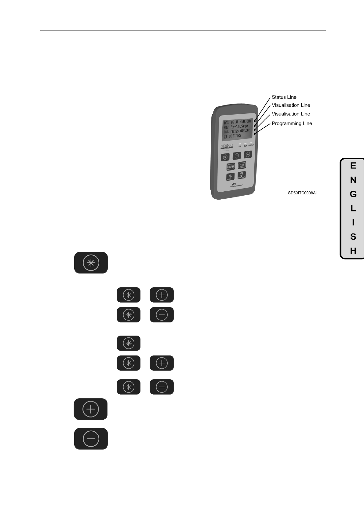
The SD500 membrane display is a removable display for remote installation, as shown in the
illustration. The display integrates three LEDs indicating the drive operating status, an LCD display
screen with 4 lines of 16 characters and control keypad and setting parameters.
.
Figure 1.1 Display and Keypad Unit
1.1.1. LED Status Indicators.
Leds show at any time and simply for the user, if the SD500 is powered, provides output voltage
or a fault has taken place.
Figure 1.2 Display Status
POWER ELECTRONICS
SD500
DISPLAY AND CONTROL KEYPAD UNIT
11
1.1.2. Alphanumeric LCD Display Screen.
The SD500 display counts with a four-line LCD screen with sixteen characters per line (16x4).
Each line has different functions.
Status Line: Is the upper line.
Always present and shows the SD500 status
(RUN, STP, etc…).
It also shows the motor output current and speed.
It is not configurable by the user.
Display Line 1: Second screen line.
Always present and allows the user to select the
different variables within the display menu.
It is configurable by the user.
Display Line 2: Third screen line.
Always present and allows the user to select the
different variables within the display menu.
Programming Line: The lower line
The user can view and set the different SD500
parameters
Figure 1.3 Display lines detail
1.1.3. Control Keypad
The keypad items have different function depending on their individual or combined use:
Authorise to enter into a parameter group to access the subgroups. In case a
group does not have subgroups, the access would be straight to the group
parameters.
Modifying numeric parameters:
Modifying parameter numbered options:
Scroll through the parameter groups. Within a parameter group, it is possible to
browse the different parameters in ascending order. It also allows setting
(increase) the value of configurable parameters.
Same function than the previous key. However, downstream. It also allows
setting (decrease) the value of configurable parameters.
Y Pressed simultaneously the value is increased.
Y Pressed simultaneously the value is decreased.
Pressing this key, the user will have access to the option
extended description.
Y Pressed simultaneously is possible to pass the
different codes in ascending order.
Y Pressed simultaneously is possible to pass the
different codes in descending order.
SD500
POWER ELECTRONICS
12
DISPLAY AND CONTROL KEYPAD UNIT
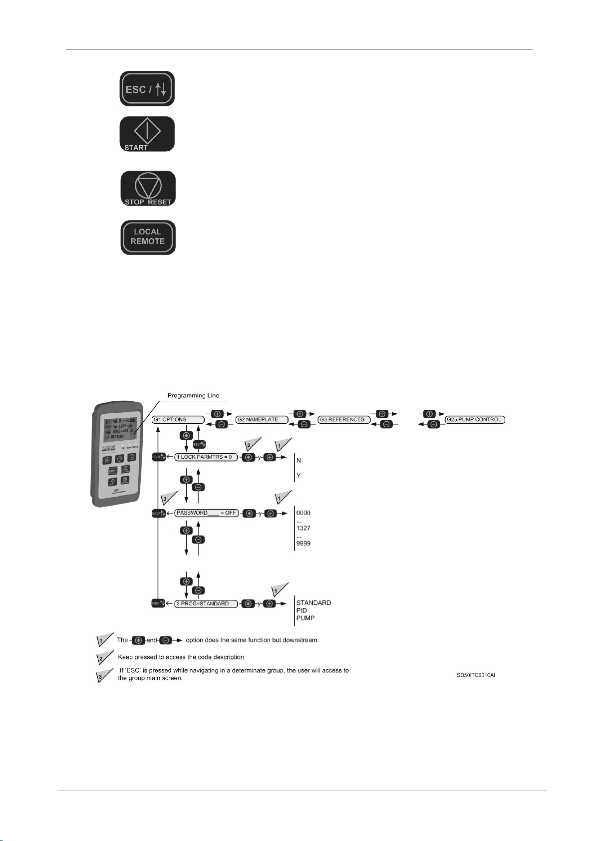
Pressing for a 2 second period (approximately), the cursor changes within the
different lines configurable by the user. It also allows to exit from a menu
location to a previous one.
Pressing this key, the drive starts if it is configured in local control mode (check
equipment configuration). This button will only operate whenever the equipment
is configured in local control mode.
Pressing this key stops the drive if it is running. In case the equipment is at
fault, pressing this button will reset the drive whenever the fault conditions have
disappeared. This button will only work when the equipment is configured in
local control.
Pressing this key, the drive will change from remote mode to local mode and
vice versa. To activate this key functionality, the parameter [G1.12 ENB/DIS
L/R] must be set to ‘E’ (Enabled). Pressing the key once, the drive switches to
be controlled locally so the start command and the speed reference must be set
in the display. The symbol “►” appears in the status line showing that the
display is in local mode. Pressing the key again, the drive switches to remote
mode, communications mode, or PLC mode, depending on the drive previous
configuration. Also, the symbol “►” disappears from the status line of the
display.
Note: There must be an elapsed time of two seconds between keystrokes for
changes to take effect.
The following figure shows a programming example, indicating the previous explication.
Figure 1.4 Parameters navigation example

POWER ELECTRONICS
SD500
STATUS MESSAGES
13
Screen
Name
Description
FLT
Fault trip
The drive is in fault state
DCB
DC Brake
The SD500 has injected DC current to stop the motor.
STP
Stopping
The drive is decreasing the output frequency due to a stop order.
DCL
Decelerating
The drive is decreasing the output frequency. The motor is decreasing its
speed, it is decelerating.
ACL
Accelerating
The drive is increasing the output frequency. The motor is increasing its
speed, its accelerating.
RUN
Running
The drive is operating at reference speed. The motor will keep the introduced
speed. Operating in nominal rate.
RDY
Ready
The drive is ready for commissioning.
2. STATUS MESSAGES
The upper line of the display corresponds to the status line. In this line we can see the equipment status,
motor mean current consumption (A), and motor speed (Hz). Always visible in the display screen and it
can not be modified by the user.
Figure 2.1 Description of the Status Line
Note: The user can access to the displayed information in the status line through the Modbus communication. Consult
section “Modbus Communication”.
2.1. Status Messages List

SD500
POWER ELECTRONICS
14
STATUS AND VISUALIZATION SCREENS
Screen
Units
Description
Mtr I out=0.0
MTR O/P current
A
Shows the current running through the motor, corresponding to the second field of the status line
OFF 0.0A +0.0Hz
Mtr Freq= 0.00Hz
Motor Frequency
Hz
Shows the motor frequency
Mtr Sp= 0rpm
Motor Speed(rpm)
rpm
Shows the motor speed in rpm
Mtr FBSp=+0rpm
MTR FBK Speed
rpm
Shows the motor encoder speed. The value will be only shown if an encoder board has been
installed in the drive.
Mtr Vout=0V
MTR O/P voltage
V
Shows the motor voltage
Mtr Pow = 0.00kW
MTR O/P power
kW
Shows the motor instantaneous power consumption
Mtr Torqe = 0.0%
MTR O/P torque
% Motor torque
Shows the torque applied to the motor.
EncMon= 0 Hz (*)
Hz
Shows the encoder speed in terms of motor frequency.
PulMo = 0 kHz (*)
kHz
Shows the encoder speed in terms of encoder pulses.
3. STATUS AND VISUALIZATION SCREENS
These screens show all time the SD500 input and output (signals and dynamic parameters) status. Display
lines are lines 2 and 3. Anyway, the user can select in each line the parameter to visualise.
In order to select a parameter, the user must place the cursor in lines 2 and 3 pressing during 2 seconds,
ESC /
. so that the cursor will jump from one line to the other. Once located in lines 2 and 3, the user
can navigate as done in the programming line (line 4) and visualise the selected parameter. Once the
parameter has been chosen, it is saved in the display memory. This way, when the display is powered, it
will show the last selected parameter in lines 2 and 3.
By the use of these two lines the user can choose a parameter to see and obtain further information in a
simple and easy way.
Figure 3 Display Lines Description
3.1. Screens SV.1 – Motor Visualization
(*) Available if parameter G19.1.1 =VECTOR

POWER ELECTRONICS
SD500
STATUS AND VISUALIZATION SCREENS
15
Screen
Units
Description
Bus vol= 528V
Bus voltage
VDC
Shows the DC voltage measured in the driver bus.
Temperature=27ºC
Temperature
ºC
Shows the internal temperature of the drive.
Screen
Units
Description
ANLG IN1 = +0.0V
A|1 Monitor
V
Shows the Analogue Input 1 mean value.
ANLG IN2 = +0.0mA
A|2 Monitor
mA
Shows the Analogue Input 2 mean value.
DigI= 00000000
Dig I/P Status
-
Shows the activation or rest status of the Digital Inputs, from left to right ED8 to ED1.
ANL OUT1 = 0.0%
Anl Out1 Monitor
%
Shows the value of the Analogue Output 1.
ANL OUT2 = 0.0%
Anl Out2 Monitor
%
Shows the value of the Analogue Output 2.
DOstatus= 0-00
Dig Output status
-
Shows the status of the digital outputs in the following order: SD1-Relay2 Relay1.
Screen
Units
Description
Inv.Power=
Inv.Power
kW
Shows the drive capacity in kW
Inv. S/W
Inv.SW
0x103
Shows the last software version installed in the drive Ex. 0x103 v1.03
SW Disp=
Display Rev Num
1.2_0_0
Shows the last software version installed in the display.
Screen
Units
Description
S=0.0% F=0.0%
Set- Fdb PID
%
Shows the PID set point value of the analogue PID (left) and the sensor value that sends the
feedback signal (right).
PID Out=+0.00%
PID Out
%
Shows the t PID Output
3.2. Screens SV.2 – Drive Visualization
3.3. Screens SV.3 – External Visualization
3.4. Screens SV.4 – Internal Visualization
3.5. Screens SV.5 – PID Visualization
This display group appears when the parameter [G1.3 PROG] has been set to the PID option.

SD500
POWER ELECTRONICS
16
STATUS AND VISUALIZATION SCREENS
Screen
Units
Description
S=0.0% F=0.0%
Set-Fdb PID
%
Shows the PID reference value of the analogue PID (left) and the sensor value that sends the
feedback signal (right).
Sal PID=+0.00%
PID OUTPUT
%
Shows the PID output.
No Bmb Ma=0
Num Pumps on
-
Shows the number of pumps running
Screen
Units
Description
1 MREF1= 10.00%
Multireference1
%
When operating with a single local reference in PID mode, use the value set [SV8.4.1 MREF1]
The speed applied in each case will depend on the activation status of the digital inputs
configured with the following options:
[G4.1.8 ED6 = ′MRefPID-H′]
[G4.1.9 ED7 = ′MRefPID-M′]
[G4.1.10 ED8 = ′MRefPID-L′]
The assignment is done as shown on the following table:
DIGITAL OUTPUTS
REFERENCE PID
ED6=00
ED7=00
ED8=00
0 0 X
G25.1.1 ‘M_Ref1’
0 X 0
G25.1.2 ‘M_Ref2’
0 X X
G25.1. ‘M_Ref3’
X 0 0
G25.1.4 ‘M_Ref4’
X 0 X
G25.1.5 ‘M_Ref5’
X X 0
G25.1.6 ‘M_Ref6’
X X X
G25.1.7 ‘M_Ref7’
2 MREF2= 20.00%
Multireference2
%
3 MREF3= 30.00%
Multireference3
%
4 MREF4= 40.00%
Multireference4
%
5 MREF5= 50.00%
Multireference5
%
6 MREF6= 50.00%
Multireference6
%
7 MREF7= 50.00%
Multireference7
%
3.6. Screens SV.8 – Pump Macro Visualization
This display group is shown when the parameter [G1.3 PROG] is set as the ‘PUMPS’ option.
3.6.1. Subgroup SV8.4 – References
In order to facilitate access to the configuration of different references, this display group is
programmable. Its function is the same as the parameter group [G25.1 References] found on the
pump application program.

POWER ELECTRONICS
SD500
PROGRAMMING PARAMETER DESCRIPTION
17
Screen / Default Value
Name /
Description
Range
Function
Set on
RUN
1 LOCK PARMTRS= N
Lock Parameters
G1.1 / Parameters
lock N Y
Enables a total lockage of the SD500 parameters. This lockage is
enabled after introducing on screen [G1.1b] a password.
DESCRIPTION
FUNCTION
N=NO
Lock is disabled
Y=YES
Only screen [G1.1 Lock Parameters] can
be modified.
NO
PASSWORD= 0
Lock Password
G1.1b/ Access
Password
OFF,
0000 to 9999
Enables a password entrance to lock the parameters and prevent non
authorised modifications within the configuration.
When [G1.1 LOCK PARMTRS'] Y is selected, this screen appears
automatically.
Unlock: In [G1.1 = S] set N NO. The screen PASSWORD=0 will
appear.
YES
ERRPWD= XXXX
Password Clue
G1.1c / Unlock
recovery clue
0000 to 9999
Provides information for the lock code recovery:
Unlock password = (XXXX/2)-3.
YES
4. PROGRAMMING PARAMETER DESCRIPTION
The various parameters found in the SD500 are arranged in functional groups (G1, G2, G3,…). To access
the screens or subgroups found on a lower level press the key. Once the parameter has been
accessed, it may show a numeric value or an option list.
Figure 4.1 Programming Line Detail
The next section shows the screen lists and the different configuration options.
4.1. Group 1 – G1: Options Menu

SD500
POWER ELECTRONICS
18
PROGRAMMING PARAMETER DESCRIPTION
Screen / Default Value
Name /
Description
Range
Function
Set on
RUN
2LOCK SCRENS= N
ViewLock Screens
G.1.2 / Screen
Lock N Y
Allows the user to lock the access to the different SD500 parameter
groups, excluding the [G1] parameter group. This lockage is enabled after
introducing on screen [G1.2b] a password
DESCRIPTION
FUNCTIÓN
N=NO
No, lockage is not active.
Y=YES
Screen lock is active.
NO
PASSWORD = 0
Enter Password
G1.2b/ Password
OFF,
0000 to 9999
Allows the user to introduce a password to lock the screen display.
When on screen [G1.2 LOCK SCRENS], Y is selected, this screen will
appear automatically.
Unlock: In [G1.2=′Y] set N NO. The screen PASSWORD= 0 appears.
YES
ERRORWD= XXXX
Clue
G1.2c / Unlock
recovery
password
0000 to 9999
Provides the information for the lock code recovery:
Unlock Password = (XXXX/2)-3.
YES
3 PROG= STANDARD
Program Select
G1.3 / Program
activation
STANDARD
PID
PUMP
Select additional functions.
When PID is selected, the drive is in PID control mode. This mode
parameter setting is done in group [G6 ‘PID Control’]. Thus, new
functionality will be available in some parameters such as Digital Inputs in
group [G4], and visualization group [SV5 ‘PID Visualization’].
When PUMP is selected, an extended available function will appear for
the pump control [G25].
The screen group [G25] will remain hidden while the pump program is
defused. Furthermore, another available configuration options relative to
the pump control found in other parameters will not appear, as well as the
multi-reference parameters [G14] due to the fact that those settings will
be carried out from group G25. The visualization group [SV8 ‘Pump
Macro Visualization’] is displayed
NO
4 LANGUA= ENGLISH
Languag selection
G1.4 / Language
display
ENGLISH
Shows the users operating language.
NO
5 INITIALIZE= NO
Parameter Init
G1.5 / Default
values initialisation
NO
YES
Initialise the parameters to reset the factory default settings.
DESCRIPTION
FUNCTION
NO
No parameter has been initialised
YES
All parameters have been initialised
NO
6 UPLOAD= N
Eloader Upload
G1.6 / Save
display
parameters
N
Y
Save the complete drive parameter configuration
NO
Upload STS=
Upload Status
G1.6b / Uploading
parameter status
0 to 100%
Show the parameter uploading process
NO
7 DOWNLOADM= N
Eloader Download
G1.7 /
Downloading
parameters
N
Y
Recovery of the parameter complete configuration previously saved in the
memory
NO
DownloadSts=
Download Status
G1.7b /
Downloading
parameter status
0 to 100%
Show the parameter downloading process from the memory.
NO
8 Changed Para= N
ViewChangedParam
G1.8 / Changed
parameter display
N
Y
Show the parameters that have changed their values from their default
value. This way, the user can identify which parameters have changed
and the parameters adjusted to the default value are hidden.
Note: Enabling this function may cause the display to run slowly. Use this
functionality only when needed.
YES

POWER ELECTRONICS
SD500
PROGRAMMING PARAMETER DESCRIPTION
19
Screen / Default Value
Name /
Description
Range
Function
Set on
RUN
9 ADMIN PW= 0
Admin_Serv PWD
G1.9 / Software
Administration
0 to 65535
Restricted for internal use.
YES
10 LCDContra= 60
Display Contrast
G1.10 / Set
display contrast
0 to 63
Enables the display contrast set.
YES
11 FAN= Run
FAN Control
G1.11 / Drive Fan
Control
DuringRun
Always ON
Temp Ctrl
The user will be able to decide the drive fan operating mode.
OPTION
FUNCTION
DuringRun
The drive fans will connect with the start command and
disconnect three minutes after the drive stops.
Always
ON
The fans are permanently working whenever the drive
is powered.
Temp Ctrl
The fan will connect at 51ºC and disconnect below
47ºC.
YES
12 ENB/DIS L/R=D
Enb/Ds Key Lc/Re
G1.12 / LOCAL /
REMOTE key
enabling
D
E
The user will be able to enable or disable the operation of the LOCAL /
REMOTE key of the display:
OPTION
FUNCTION
D=DISABLED
LOCAL / REMOTE key is disabled.
E=ENABLED
LOCAL / REMOTE key is enabled.
Note: For further information about the operation of this key go to section
‘1.1.3 Control Keypad’.
NO
Screen / Default Value
Name /
Description
Range
Function
Set on
RUN
1 ACi/pVolt= 380V
AC Input Volt
G2.1.1 / Input
Voltage
170 to 230V
320 to 480V
In order to set the input voltage.
Note: The default setting value and this parameter range will vary
depending on the drive supply voltage:
220V220
400V380
YES
2 I/P Freq= 50Hz
Input Frequency
G2.1.2 / Input
frequency
50 – 60Hz
In order to set the input frequency. If the user changes from 50Hz to
60Hz, the parameters related to the frequency (or rpm) defined in a value
greater than 50Hz will change to 60Hz.
However, if the frequency is changed from 60Hz to 50Hz, the parameters
related to the frequency (or rpm) defined in a value lower than 60Hz will
change to 50Hz.
NO
3 TrimPwr%= +100%
Trim Power %
G2.1.3 / Power
display setting
70 to 130%
Set the output power display, increasing its value if it is lower than
expected or otherwise reducing it to coincide with the real value.
YES
Screen / Default Value
Name /
Description
Range
Function
Set on
RUN
1 MTRPWR= 0.0kW
[1]
Motor Power
G2.2.1 / Motor
rated Power
0.2 to 185kW
Set the power to motor rated values in accordance with the nameplate.
Note: When this parameter is changed, parameters [G2.2.2 MTR CUR],
[G2.2.3 NOLOADC] and [G2.2.4 MTR VOLT] are automatically modified.
NO
2 MTR CUR= 0.0A
[1]
Motor Current
G2.2.2 / Motor
rated current
1.0 to 200.0A
Set the motor nominal current in accordance with the nameplate.
Note: The value of this parameter will be automatically configured when
setting parameter [G2.2.1 MOTRPWR].
NO
3 NOLOADC= 0.0A
[1]
No load Current
G2.2.3 / No load
current
0.5 to 200A
Set the current measured of the motor at rated frequency without load. If
difficulties found when measuring the current without load, this setting
should be between 30% and 50% of the motor nameplate rated current.
Note: The value of this parameter will be automatically configured when
setting parameter [G2.2.1 MOTRPWR].
NO
4.2. Group 2 – G2: Nameplate
4.2.1. Subgroup 2.1 – G2.1: Drive Parameters
Note: If all of these values are not introduced correctly, the SD500 would not work properly. Whenever the motor
nameplate offers multiple options or the star-delta coil configuration can be altered make sure to introduce the data
correctly in accordance with its configuration.
4.2.2. Subgroup 2.2 – G2.2: Motor Parameters

SD500
POWER ELECTRONICS
20
PROGRAMMING PARAMETER DESCRIPTION
Screen / Default Value
Name /
Description
Range
Function
Set on
RUN
4 MTR VOLT= 0V
Motor Voltage
G2.2.4 / Motor
nominal voltage
180 to 480V
Set the motor rated voltage according to its nameplate.
Note: The value adjusted in this parameter will be automatically set to 0V
when changing the value of parameter [G2.2.1 MTRPWR]. Be careful of
setting the motor rated voltage after changing the motor power
parameter.
NO
5 POLE Number= 4
[1]
POLE Number
G2.2.5 / Motor
Poles
2 to 48
Set the number of poles in the motor according to its nameplate.
NO
6 ADJTSPD= 100.0%
FineAdjustSpeed
G2.2.6 / Fine
speed setting
0.1 to 6000%
Set the motor fine rated speed in accordance with the nameplate.
YES
7 EFICIENC= +85%
[1]
Efficiency
G2.2.7 / Motor
Efficiency
70 to 100%
Set the motor efficiency according to its nameplate.
NO
8 MTR FRC = 50.00Hz
Motor Frequency
G2.2.8 / Motor
frequency
30 to 400Hz
Set the motor frequency to rated value according to its nameplate.
NO
9 MTRCOOL=SELF
Motor Cooling
G2.2.9 / Motor
cooling
SELF
FORCED
Sets the drive with the motor characteristics to control. Provides
information for the thermal electric protection based on the motor thermal
model.
OPTIÓN
FUNCTION
SELF
Motor Self cooling
FORZAD
Motor with forced cooling
YES
Screen / Default Value
Name / Description
Range
Function
Set on
RUN
1 REF1 SP= LOCAL
Speed Reference 1
G3.1 / Speed
Reference Source 1
LOCAL
AI1
AI2
AI3
AI4
MDBUS
COMMS
PLC
Select the speed reference source associated with each control mode:
- The reference source [G3.1 ‘REF1 SP’] is associated with the main
control model [G4.1.1 ‘CONTRL MODE 1’].
- The reference source 2 [G3.2 ‘REF2 SP’] is associated with the
alternative control mode [G4.1.2 ‘CONTRL MODE 2’].
OPTION
FUNCTION
LOCAL
The reference will be introduced by the use of the
keypad and set on [G3.3LOCAL].
AI1
The reference will be introduced through the Analogue
Input 1.
AI2
The reference will be introduced through the Analogue
Input 2.
AI3
The reference will be introduced through the Analogue
Input 3.
Note: This option is only available if the I/O expansion
board has been installed.
AI4
The reference will be introduced through the Analogue
Input 4.
Note: This option is only available if the I/O expansion
board has been installed.
MDBUS
The reference will be installed by the use of MODBUS
communications.
COMMS
The reference will be installed by the use of the optional
communications board installed in the drive.
Note: This option is only available if any of the
communication boards have been installed.
PLC
The reference will be introduced through a
programmable Logic Controller.
Note: This option is only available if the optional PLC
board has been installed.
Note: In case an unavailable option is selected, the parameter will return
to the previously selected option.
NO
2 REF2 SP= LOCAL
Alt Speed Ref
G3.2 / Speed
Reference Source 2
NO
3 LCLSP= 0.00Hz
Local Speed
G3.3 / Local Speed
Reference
[G19.2.5]
to [G10.1]
The user can set the motor spinning speed value whenever the speed
reference has been set as LOCAL.
YES
[1] Value that depends on the drive rated current.
Note: If all of these values are not introduced correctly, the SD500 would not work properly. Whenever the motor
nameplate offers multiple options or the star-delta coil configuration can be altered, make sure to introduce the data
correctly in accordance with its configuration.
4.3. Group 3 – G3: References

POWER ELECTRONICS
SD500
PROGRAMMING PARAMETER DESCRIPTION
21
Screen / Default Value
Name / Description
Range
Function
Set on
RUN
4 REF1 TQ = LOCAL (*)
G3.4 / Torque
Source Reference 1
LOCAL
AI1
AI2
AI3
AI4
MDBUS
COMMS
PLC
Allows to select supply 1 or supply 2 of the torque reference:
OPTION
FUNCTION
LOCAL
Reference will be introduced through keyboard and
will be adjusted in G3.6 ‘Local Torque Reference’.
AI1
The reference will be introduced through the analog
input 1.
AI2
The reference will be introduced through the analog
input 2.
AI3
The reference will be introduced through the analog
input 3.
AI4
The reference will be introduced through the analog
input 4.
MDBUS
The reference will be introduced through Modbus.
COMMS
The reference will be introduced through the
communications.
PLC
The reference will be introduced through PLC.
NO
5 REF2 TQ = LOCAL (*)
G3.5 / Torque
Source Reference 2
NO
6 LclTQ = 0 % (*)
G3.6 / Local Torque
Reference
-180 to
180%
Allows the user to set the torque value of the motor if the torque reference
source has been adjusted to “LOCAL”
YES
Screen / Default Value
Name /
Description
Range
Function
Set on
RUN
1 CONTROL MODE1= 1
Control Mode 1
G4.1.1 / Main
Control Mode
LOCAL
REMOTE
MODBUS
COMMS
PLC
The user is able to set the main control mode to order the command
functions (Start/Stop, Reset, …).
OP.
DESCRIP.
FUNCTION
0
LOCAL
The drive is controlled from the keypad.
1
REMOTE
The drive is controlled from the control
terminals.
3
MODBUS
The drive is controlled through the
communications bus, integrated in the
equipment.
4
COMMS
The drive control is carried out by the use of
any of the optional communication boards.
Note: This option is only available if any of the
communication boards have been installed.
5
PLC
The drive control is carried out through a
programmable Logic Controller.
Note: This option is only available if the
optional PLC board has been installed.
Note: In case an unavailable option is selected, the parameter will return
to the previously selected option.
NO
2 CONTROL MODE2= 1
Alt Ctrl Mode
G4.1.2 /
Alternative Control
Mode
LOCAL
REMOTE
MODBUS
COMMS
PLC
Enables the user to set the secondary control mode to order the
command functions ( Start, Stop, Reset…)
The control mode 2 will enable exclusively through digital inputs.
Therefore, set any of these to [15 CTR/REF 2]. When the input is
active, it will operate in the auxiliary control mode, inhibiting the main
mode.
OP.
DESCRIP.
FUNCTION
0
LOCAL
The drive is controlled from the keypad.
1
REMOTE
The drive is controlled from the control
terminals.
3
MODBUS
The drive is controlled through the
communications bus, integrated in the
equipment.
4
COMMS
The drive control is carried out by the use of
any of the optional communication boards.
Note: This option is only available if any of the
communication boards have been installed.
5
PLC
The drive control is carried out through a
programmable Logic Controller.
Note: This option is only available if the
optional PLC board has been installed.
Note: In case an unavailable option is selected, the parameter will return
to the previously selected option.
NO
4.4. Group 4 – G4: Inputs
4.4.1. Subgroup 4.1 – S4.1: Digital I/P
(*) Available if parameter G19.1.1 =VECTOR

SD500
POWER ELECTRONICS
22
PROGRAMMING PARAMETER DESCRIPTION
Screen / Default Value
Name /
Description
Range
Function
Set on
RUN
3 DI1= START (+)
Digital I/P 1
G4.1.3 /
Multifunction
Digital Input 1
Configuration
NONE
MRefPID-H
MRefPID-M
MRefPID-L
START (+)
START (-)
RESET
EXT TRIP
DIS START
INCH 1
SPEED-L
SPEED-M
SPEED-X
XCEL-L
XCEL-M
3 WIRE
CTR/REF 2
UP
DOWN
RESERVED
POT CLEAR
AnalogHLD
PIDOPLoop
RESERVED
Pre-Excit
Speed/Torque
ASR GAIN2
ASR P/PI
ThermalIn
INCH (+)
INCH (-)
Tq OFFSET
Digital Inputs configuration for individual use.
OPTION
FUNCTION
None
Not programmed entry.
MRefPID-H
High Bit for the PID multireference. See [Group 14 –
′Multi-references′] (NO).
Note: This option is only available for Digital Input 6.
MRefPID-M
Medium Bit for the PID multireference. See [Group
14 – ′Multi-references′] (NO).
Note: This option is only available forDigital Input 7.
MRefPID-L
Low Bit for the PID multireference. See [Group 14 –
′Multi-references′] (NO).
Note: This option is only available for Digital Input 8.
START (+)
In order to command the ‘Direct Start’ order through
the selector (NO). This option will not work if there is
any digital input programmed as ‘3 WIRE’, ‘UP’, or
‘DOWN’.
START (-)
In order to command the ‘Inverse Start order through
the selector (NO). This option will not work if there is
any digital input programmed as ‘3 WIRE’, ‘UP’, or
‘DOWN’.
RESET
In order to command the ‘Reset’ order through
digital inputs. (NO)
EXT TRIP
Allows an extreme fault generation in order to stop
the drive through digital inputs (NO). Is advisable to
invert the digital input logic configured as Extreme
Fault and set it as contact (NC). See parameter
[G4.1.16].
DIS START
In order to stop the drive removing the motor output
power supply forcing a stop by inertia. (NO)
INCH 1
In order to enable the speed reference programmed
in [G15.1 ′InchFq′]. (NO)
SPEED-L
[1]
Bit 0 speed reference. Allows selecting the multiple
preconfigured speed references. See [Group 14 –
′Multi-references′] (NO)
SPEED-M
[1]
Bit 1 speed reference. Allows selecting the multiple
preconfigured speed references. See [Group 14 –
′Multi-references′] (NO)
SPEED-H
[1]
Bit 2 speed reference. Allows selecting the multiple
preconfigured speed references. See [Group 14 –
′Multi-references′] (NO)
SPEED-X
[1]
Bit 3 speed reference. Allows selecting the multiple
preconfigured speed references. See [Group 14 –
′Multi-references′] (NO)
XCEL-L
Bit 0 for alternative acceleration ramps. Allows the
selection of the multiple preconfigured
acceleration/deceleration ramps. See [Subgroup
5.16 – ‘Alternative Ramps’]
XCEL-M
Bit 1 for alternative acceleration ramps Allows the
selection of the multiple preconfigured
acceleration/deceleration ramps. See [Subgroup
5.16 – ‘Alternative Ramps’]
3 WIRE
‘Speed through Buttons’ function’.
Example:
DI1 = 1 START(+) (NO)
DI2 = 14 3 WIRE (NC)
DI3 = 17 UP (NO)
DI4 = 18 DOWN (NO)
This way, the DI1 button orders to start and the DI2
orders to stop. The DI3 and DI4 buttons allow the
user to increase or decrease the speed.
CTR/REF 2
Enables the alternative control mode programmed in
[G4.1.2. ′Alt Ctrl Mode′] (NO).
[1]
Available if [G1.3 PROG=STANDARD]
Note: Continues on the following page.
NO
4 DI2= START(-)
Digital I/P 2
G4.1.4 /
Multifunction
Digital Input 2
Configuration
5 DI3= DIS START
Digital I/P 3
G4.1.5 /
Multifunction
Digital Input 3
Configuration
6 DI4= EXT TRIP
Digital I/P 4
G4.1.6 /
Multifunction
Digital Input 4
Configuration

POWER ELECTRONICS
SD500
PROGRAMMING PARAMETER DESCRIPTION
23
Screen / Default Value
Name /
Description
Range
Function
Set on
RUN
7 DI5= SPEED-L
[1]
Digital I/P 5
G4.1.7 /
Multifunction
Digital Input 5
Configuration
NONE
MRefPID-H
MRefPID-M
MRefPID-L
START (+)
START (-)
RESET
EXT TRIP
DIS START
INCH 1
SPEED-L
SPEED-M
SPEED-X
XCEL-L
XCEL-M
3 WIRE
CTR/REF 2
UP
DOWN
RESERVED
POT CLEAR
AnalogHLD
PIDOPLoop
RESERVED
Pre-Excit
Speed/Torque
ASR GAIN2
ASR P/PI
ThermalIn
INCH (+)
INCH (-)
Tq OFFSET
Note: Previous page continuation.
DESCRIPTION
FUNCTION
UP
Assigns to the digital input the function of increasing
the speed reference by the use of a button(NO). The
reference limits will be the ones set on [G.10 LIMITS].
DOWN
Assigns to the digital input the function of decreasing
the speed reference by the use of a button(NO). The
reference limits will be the ones set on [G.10 LIMITS].
RESERVED
-
POT CLEAR
Deletes the speed reference memory set with
motorized potentiometer. This way, even if parameter
[G4.18 ‘SaveMot Frq’] is set as ‘YES’, when restarting
the drive, the drive will operate depending on the
established reference in [G3.3 ‘LOCAL’].
AnalogHLD
Allows set a speed reference from an analog input to
the value present at the activation time. When this
digital input is active, the drive will ignore any change
produced in the analog input reference (NO).
PIDOPLoop
Allows disabling the PID function. When it is disabled,
the control PID will be resumed.
Note: This option must be used when the PID
reference is set by analogue input. If PID reference is
set by display, use option ‘INCH1’.
RESERVED
-
Pre-Excit
Enables the motor pre-excitation activation, before
start. The user can adjust this functionality in
parameters [G7.1 ‘START’], [G7.12 ‘DCSt T’] and
[G7.13 ‘DC Curr’].
Speed/Torque(*)
Allows setting speed mode (NO) or torque mode (NC).
ASR GAIN2(*)
Allows changing the gain of the speed controller to
[G19.3.7] after [G19.3.10].
ASR P/PI (*)
Allows disabling the Integral gain of the speed
controller (NC).
Thermalln
Assigns the over temperature trip function when a
PTC sensor is connected to a digital input. Therefore,
the PTC should be connected between a digital input
and the common terminal. Furthermore, this input
should be configured as (NC) in the parameter
[G4.1.16 - ′DCTy′] and the overheat protection must
be enabled in parameter [G11.23 ‘OvHM’].
INCH (+)
In order to define the direct starting fix speed
reference to the one set in parameter [G15.1 -′InchFq′]
INCH (-)
In order to define the direct starting fix speed
reference to the one set in parameter [G15.1 -′InchFq′]
Tq OFFSET(*)
In order to activate the Tq OFFSET option.
Parameters are configured in screens [G10.8.6] to
[G10.8.8].
NO
8 DI6= SPEED-M
[1]
Digital I/P 6
G4.1.8 /
Multifunction
Digital Input 6
Configuration
9 DI7= SPEED-H
[1]
Digital I/P 7
G4.1.9 /
Multifunction
Digital Input 7
Configuration
10 DI8= INCH 1
Digital Input 8
G4.1.10 /
Multifunction
Digital Input 8
Configuration
14 DIOnF= 10ms
DI On Filter
G4.1.14 / Digital
Input activation
delay
0 to 10000ms
In order to set the delay time when activating the digital input. In case any
variation occurs within a smaller time gap, the input will remain disabled.
YES
15 DIOffF= 3ms
DI Off Filter
G4.1.15 / Digital
Input
deactivation
delay
0 to 10000ms
In order to set the delay time when disabling a digital input. In case any
variations occur within a smaller time gap, the input will remain enabled.
YES
16 DCTy= 00000000
DiContactType
G4.1.16 / Digital
input contact
type selection
00000000
to
XXXXXXXX
Allows defining the digital inputs as usually opened contactors (NO). or
usually closed (NC)
OPTION
FUNCTION
0
Contact normally open (NO)
X
Contact normally closed (NC)
The assignment order is DI1, DI2, …, DI8 starting from the bit placed
farthest to the right.
NO
17 DiScan= 1ms
Di Scan Time
G4.1.17 /
Multireference
delay time
1 to 5000ms
In order to set how much time must pass to refresh the digital inputs
configured as multireference.
NO
18 SaveMot Frq= N
Save motpot freq
G4.1.18 / Save
operating
frequency
motorised
Potentiometer
NO
YES
Save automatically the speed reference defined by the motorised
potentiometer.
YES
[1]
These parameters default values depends on the program mode set in [G1.3 PROG].
(*) Available if parameter G19.1.1 =VECTOR

SD500
POWER ELECTRONICS
24
PROGRAMMING PARAMETER DESCRIPTION
Screen / Default Value
Name /
Description
Range
Function
Set on
RUN
1 An1PT= 0-10v
Ain1PolarityType
G4.2.1 / Analog
Input Mode
Selection
0-10V
-/+10V
The user is able to select between the single-pole or bipolar analog input
mode.
OPTION
FUNCTION
0-10V
Single-pole of 0-10V
10V
Bipolar of 10V
In addition to change this parameter, the user should ensure that the
analog input wiring is correct as shown in the Hardware and Installation
Manual.
NO
2 Ain1LPF= 10ms
Ain1LPF
G4.2.2 / Low
Pass Filter for
Analog Input 1
0 to
10000ms
Enables the setting of the time response against a change produced in the
speed reference, so that it can reduce the speed fluctuation due to
unstable signs or noise. This results that the response becomes slower.
YES
3 A1MnV= +0.00V
Ain1 Min V
G4.2.3 / Analog
Input 1 Minimum
Range
0 to [G4.2.5]
In order to define the minimum voltage for the analog input 1 according to
the connected sensor characteristics.
YES
4 A1MnRf= +0.00%
An1MxV
G4.2.4 / Analog
Input 1 Minimum
Range Speed
0 to 100.00%
The user is able to set the speed reference corresponding to the analog
input 1 minimum range. It corresponds to the minimum voltage level set in
[G4.2.3 ‘Ain1LPF’]. It is configured to introduce the speed reference
through the analog input. The value is a percentage of the frequency
adjusted in parameter [G4.2.12 ‘MxFqA’].
YES
5 A1MxV= +10.00V
Ain1 Max V
G4.2.5 / Analog
Input 1 Maximum
Rage
[G4.2.3] to
10.00V
Defines the maximum voltage for the analog input 1, according to the
connected sensor characteristics.
YES
6 A1MxR= +100.00%
Ain1 Max Ref
G4.2.6 / Analog
Input 1 Maximum
Range Speed
0 to 100.00%
The user is able to set the speed reference corresponding to the analog
input 1 minimum range. It corresponds to the minimum voltage level set in
[G4.2.5 ‘A1MxV’]. It is configured to introduce the speed reference through
the analog input. The value is a percentage of the frequency adjusted in
parameter [G4.2.12 ‘MxFqA’].
YES
7 An1NgMn=+0.00V
[1]
Ain1 neg min V
G4.2.7 / Analog
Input 1 Negative
Minimum Range
-10.00 to 0V
Defines the negative minimum voltage for the analog input 1, according to
the connected sensor characteristics.
YES
8 A1MnR= +0.00%
[1]
Ain1 Neg Min Ref
G4.2.8 / Analog
Input 1 Minimum
Negative Range
-100.00 to
0%
The user is able to set the speed reference corresponding to the analog
input 1 minimum negative range. Is corresponds to the minimum voltage
level set in [G4.2.7 ‘An1NgMn’]. It is configured to introduce the speed
reference through the analog input. The value is a percentage of the
frequency adjusted in parameter [G4.2.12 ‘MxFqA’].
YES
9 A1MxR= -10.00V
[1]
Ain1 Neg MaxV
G4.2.9 / Analog
Input 1 Maximum
Negative Range
-10.00 to 0V
Defines the maximum negative voltage for the analog input 1 according to
the connected sensor characteristics.
YES
10 A1MxR= -100.00
[1]
Ain1Neg Max Ref
G4.2.10 / Analog
Input 1 Maximum
Negative Range
Speed
-100.00 to
0%
The user is able to set the speed reference corresponding to the analog
input 1 maximum negative range. It corresponds to the maximum voltage
level set in [G4.2.8 ‘A1MnR’]. It is configured to introduce the speed
reference through an analog input. The value is a percentage of the
frequency adjusted in parameter [G4.2.12 ‘MxFqA’].
YES
11 A1DeLI= 0.04%
Ain1 Discre Lv
G4.2.11 / Analog
Input 1
Quantification
Level
0.04 to 10%
The user is able to set the analog input 1 quantification level. It is used
when too much noise is present within the analog input signals. The
quantification value is defined as the analog input 1 maximum percentage
value. For example, if the input maximum value is 10V and the
quantification level is 1%, the frequency will change in 0.05Hz (when the
maximum frequency is 50Hz), in 0.1V intervals. As the input voltage
increases or decreases, the output frequency will differ, removing the
fluctuation effect within the analog input value.
NO
12 MxFqA= 50.00Hz
Max Freq Ang Inp
G4.2.12 /
Maximum
frequency at
analogue input
[G19.2.5] to
[G10.1]
The user is able to set the operating frequency of the drive at the maximum
voltage input of the analogue input.
YES
4.4.2. Subgroup 4.2 – S4.2: Analog Input 1
[1]
Available if the Analog Input 1 is configured as bipolar (10V) in parameter [G4.2.1 EA1Md = 1].

POWER ELECTRONICS
SD500
PROGRAMMING PARAMETER DESCRIPTION
25
Screen / Default Value
Name /
Description
Range
Function
Set on
RUN
1 Ain2LPF= 10ms
Ain2LPF
G4.3.1 / Low Pass
Filter for Analog
Input 2
0 to 10000ms
Enables the setting of the time response against a change produced in
the speed reference, so that it can reduce the speed fluctuation due to
unstable signs or noise. This results that the response becomes slower.
NO
2 A2MnC= 4.00mA
Ain2 Min C
G4.3.2 / Analog
Input 2 Minimum
Range
0 to 20.00mA
In order to define the minimum current for the analog input 2 according to
the connected sensor characteristics.
YES
3 A2MnR= +0.00%
Ain2 Min Ref
G4.3.3 / Analog
Input 1 Minimum
Range Speed
0 to 100.00%
The user is able to set the speed reference corresponding to the analog
input 2 minimum range. It corresponds to the minimum voltage level set
in [G4.3.2 ‘A2MnC’]. It is configured to introduce the speed reference
through the analog input. The value is a percentage of the frequency
adjusted in parameter [G4.3.7 ‘MxFqA’].
YES
4 A2MxC= 20.00mA
Ain2 Max Curr
G4.3.4 / Analog
Input 2 Maximum
Range
4 to 20.00mA
Defines the maximum current for the analog input 2, according to the
connected sensor characteristics.
YES
5 A2MxR= +100.00%
Ain2 Max Ref
G4.3.5 / Analog
Input 2 Maximum
Range Speed
0 to 100.00%
The user is able to set the speed reference corresponding to the analog
input 2 maximum range. It corresponds to the maximum current level set
in [G4.3.4 ‘A2MxC’]. It is configured to introduce the speed reference
through the analog input. The value is a percentage of the frequency
adjusted in parameter [G4.3.7 ‘MxFqA’].
YES
6 A2DeLl= 0.04%
Ain2 Dze Level
G4.3.6 / Analog
Input 2
Quantification
level
0.04 to 10%
Same function as the quantification parameter shown in [G4.2.11
‘A1DeLl‘].
NO
7 MxFqA= 50.00Hz
Max Freq Ang Inp
G4.3.7 / Maximum
frequency at
analogue input
[G19.2.5] to
[G10.1]
The user is able to set the operating frequency of the drive at the
maximum voltage input of the analogue input.
YES
Screen / Default Value
Name /
Description
Range
Function
Set on
RUN
1 ACC1= 20.0s
Acc Ramp
G5.1 /
Acceleration
Ramp 1
0 to 600.0s
The user is able to set the acceleration ramp 1. The established setting
within the parameter is the time required to reach the maximum
frequency value, starting form 0Hz.This ramp will be set according to the
process necessities.
SI
2 DECEL1= 30.0s
Decel Ramp
G5.2 /
Deceleration
Ramp 1
0 to 600.0s
The user is able to set the deceleration ramp 1. The established setting
within the parameter is the time required to reach the maximum
frequency value, starting form 0Hz.This ramp will be set according to the
process necessities.
SI
4 RmpT= MaxFreq
Ramp T Mode
G5.4 / Type of
Acceleration
Ramp
MaxFreq
FrqDelta
Enables the acceleration ramp settings:
OPTION
FUNCTION
MaxFreq
Allows accelerating or decelerating with the same
ramp based on the maximum frequency,
independently from the operating frequency.
FrqDelta
Allows defining the accelerating/decelerating time
which will reach the next speed reference when
working at constant speed.
NO
5 AccPn= Linear
Acc Pattern
G5.5 /
Acceleration
Pattern
LINEAR
S CURVE
In order to set the type of acceleration depending on the application:
OPTION
FUNCTION
LINEAR
The output frequency is constant and increases/
decreases linearly.
S CURVE
Used in applications which require a soft
acceleration/deceleration, such as lifting loads. The S
curve index can be set from parameters
[G5.7 – G5.10]
NO
4.4.3. Subgroup 4.3 – S4.3: Analog Input 2
4.5. Group 5 – G5: Acceleration and Deceleration Ramps

SD500
POWER ELECTRONICS
26
PROGRAMMING PARAMETER DESCRIPTION
Screen / Default Value
Name /
Description
Range
Function
Set on
RUN
6 DecPn= Linear
Dec Pattern
G5.6 /
Deceleration
Pattern
LINEAR
S CURVE
Allows the setting of the same functions found in parameter [G5.5
‘AccPn’]
NO
7 AcSSrt= +40%
Acc S Start
G5.7 / S Curve
Acceleration
Starting Ramp
1 to 100%
The user is able to set the curve whenever the acceleration/deceleration
pattern is defined as S curve. It is used to set the S curve curvilinear
relation when starting the acceleration.
NO
8 AccSEnd= +40%
Acc S End
G5.8 / S-Curve
Acceleration
Ending Ramp
1 to 100%
The user is able to set the curve’s ramp once the
acceleration/deceleration pattern has been defined as S Curve. It is used
to set the S Curve curvilinear relation when ending the acceleration.
NO
9 DeISSrt= +40%
Dec S Start
G5.9 / S- Curve
Deceleration
Starting Ramp
1 to 100%
The user is able to set the curve whenever the acceleration/deceleration
pattern is defined as S curve. It is used to set the S curve curvilinear
relation when starting the deceleration.
NO
10 DecSEnd=+40%
Dec S End
G5.10 / S-Curve
Decelerating
Ending Ramp
1 to 100%
The user is able to set the curve’s ramp once the
acceleration/deceleration pattern has been defined as S Curve. It is used
to set the S Curve curvilinear relation when ending the deceleration.
NO
11 AccDWF= 5.00Hz
Acc Dwell Freq
G5.11 /
Acceleration
Frequency Pause
[G19.2.5] to
[G10.1]
During the acceleration process, the drive will pause at this frequency,
keeping it constant during a period of time set in parameter
[G5.12 – ′AccDWT′].
NO
12 AccDWT= 0.0s
Acc Dwell Time
G5.12 /
Acceleration Time
Pause
0 to 60s
During the acceleration process, this parameter allows to set during how
long the drive will operate at the constant frequency set in parameter
[G5.11 - AccDWF′].
NO
13 DecDWF= 5.00Hz
FDec Dwell Freq
G5.13 /
Deceleration
Frequency Pause
[G19.2.5] to
[G10.1
During the deceleration process, the drive will pause at this frequency
value, remaining constant during the period of time established in
parameter [G5.14 – ′DecDWT′].
NO
14 DecDWT= 0.0s
Dec Dwell Time
G5.14 /
Deceleration Time
0 to 60.0s
During the deceleration process, this parameter allows to set how long
will the drive be operating at the constant frequency set in parameter
[G5.13 - ′DecDWF′].
NO
15 TDedFll= 3.0s
Fault decal time
G5.15 / Fault
Deceleration Time
0 to 600.0s
To proceed with the deceleration time settings, whenever a fault occurs.
YES
Screen / Default Value
Name /
Description
Range
Function
Set on
RUN
1 ACC2= 20.0s
Acc Ramp 2
G5.16.1 /
Alternative
Acceleration
Ramp 2
0 to 600.0s
This parameter allows up to three alternative acceleration/deceleration
ramps. The main acceleration/deceleration ramps can be set in
parameters [G5.1 ‘ACC1’] and [G5.2 ‘DECEL1’].
The alternative ramps will be enabled by means of the digital inputs,
configured as multiple acceleration/deceleration references. See
parameters [G4.1.3] to [G4.1.10].
To proceed with their use, the user must select the digital inputs which
control the alternative ramps setting them as ‘XCEL-L and XCEL-M.
The setting is carried out by assigning a time value to each of the
parameters within the [G5.16.1] to [G5.16.6] groups.
The following table link the configured digital inputs as Alternative Ramps
with the selected acceleration/deceleration:
PARM.
DESCRIP
DIGITAL. I:
START/STOP
DIGITAL.I.
ACC/DEC
STOP(+)
START(-)
M
B
G5.1
ACC1 1 0 0 0
G5.2
DECEL1 0 1 0 0
G5.16.1
ACC2 1 0 0 X
G5.16.2
DEC2 0 1 0 X
G5.16.3
ACC3 1 0 X 0
G5.16.4
DEC3 0 1 X 0
G5.16.5
ACC4 1 0 X X
G5.16.6
DEC4 0 1 X X
Note: 0: Disabled y X: Enabled.
YES
2 DEC2= 20.0s
Decel Ramp 2
G5.16.2 /
Alternative
Deceleration
Ramp 2
0 to 600.0s
3 ACC3= 30.0s
Acc Ramp 3
G5.16.3 /
Alternative
Acceleration
Ramp 3
0 to 600.0s
4 DEC3= 30.0s
Decel Ramp 3
G5.16.4 /
Alternative
Deceleration
Ramp 3
0 to 600.0s
5 ACC4= 40.0s
Acc Ramp 4
G5.16.5 /
Alternative
Acceleration
Ramp 4
0 to 600.0s
6 DEC4= 40.0s
Decel Ramp 4
G5.16.6 /
Alternative
Deceleration
Ramp 4
0 to 600.0s
4.5.1. Subgroup 5.16 – S5.16: Alternative Ramps

POWER ELECTRONICS
SD500
PROGRAMMING PARAMETER DESCRIPTION
27
Screen / Default Value
Name /
Description
Range
Function
Set on
RUN
1 SEL REF= MREF
Select Reference
G6.1 / Source
Selection to
introduce the set
point
MREF
AI1
AI2
AI3
AI4
MODBUS
COMMS
PLC
The user is able to select the source to introduce the PID regulator
reference.
OPTION
FUNCTION
MREF
PID reference introduced by keypad. The different
references are set in parameter [Group 14
MULTIREFERENCES]
AI1
PID reference introduced through Analog Input 1
AI2
PID reference introduced through Analog Input 2
AI3
PID reference introduced through Analog Input 3
Note: This option is only available if the I/O expansion
board has been installed.
AI4
PID reference introduced through Analog Input 4
Note: This option is only available if the I/O expansion
board has been installed.
MODBUS
PID reference introduced through integrated Modbus
communications
COMMS
PID reference introduced through communications of any
of the optional communication boards.
Note: This option is only available whenever any of the
optional communication boards have been installed.
PLC
PID reference introduced through the equipments
programmable logic controller
Note: This option is only available whenever the PLC
optional board has been installed.
Note: Whenever an unavailable option is selected, the parameter will
return to the previously selected option.
NO
2 SEL FBK= AI1
Select Feedback
G6.2 / Source
Selection to
Introduce the
Feedback Signal
AI1
AI2
AI3
AI4
MODBUS
COMMS
PLC
In order to select the source this will introduce the feedback to close the
control loop.
OPTION
FUNCTION
AI1
Feedback signal through the Analog Input 1
AI2
Feedback signal through the Analog Input 2
AI3
Feedback signal through the Analog Input 3
Note: This option is only available whenever the I/O
expansion board has been installed.
AI4
Feedback signal through the Analog Input 4
Note: This option is only available whenever the I/O
expansion board has been installed.
MODBUS
Feedback signal through the equipment integrated
Modbus communications
COMMS
Feedback signal through communications of any of the
optional communication boards.
Note: This option is only available whenever any of the
optional communication boards have been installed.
PLC
Feedback signal through a programmable logic controller
Note: This option is only available whenever the PLC
optional board has been installed.
Note: Whenever an unavailable option is selected, the parameter will
return to the previously selected option.
NO
3 GainKp= +50.0%
Gain Kp
G6.3 / PID
Regulator Gain
0 to 1000.0%
In order to set the value of the proportional gain controller. This value
should be increased, whenever a greater control response is needed,
Note: Increasing too much this value can cause a greater system
instability
YES
4 INTEGRL= 10.0s
PID Integral
G6.4 / PID
Regulator
Integrating Time
0 to 200.0s
Set the regulator integration time. In case greater precision is needed,
increase this value.
Note: Increasing this value may slow down the system.
YES
5 T Der= 0ms
PID Differential
G6.5 / PID
Regulator
Differential Time
0 to 1000ms
Set the regulator differential time. Whenever a greater response is
needed, this value can be increased.
Note: Increasing too much this value can cause a precision loss.
YES
4.6. Group 6 – G6: PID Control
This configuration group allows adjusting the PID control of the drive. To enable this control mode it is
necessary to adjust parameter [G1.3 ‘PROG’] as ‘PID’.

SD500
POWER ELECTRONICS
28
PROGRAMMING PARAMETER DESCRIPTION
Screen / Default Value
Name /
Description
Range
Function
Set on
RUN
6 MxSL= +50.00Hz
Max Speed LIM
G6.6 / PID Upper
Frequency Limit
From [G6.8]
to 300Hz
Set the upper limit at the PID output
YES
7 MnSL= 0.00Hz
Min Speed Lim
G6.7 / PID Lower
Frequency Limit
From -300.00
to [G6.7] Hz
Set the lower limit at the PID output
YES
8 INVERT PID= N
Invert PID
G6.8 / PID Output
Inverting N Y
In order to invert the drive PID output.
OPTION
FUNCTION
N=NO
The PID regulator answers in normal mode. This means,
when the feedback value is greater than the reference
signal, the speed will be reduced. Whenever the
feedback is lower than the reference signal, the speed
will be increased.
Y=YES
The PID regulator responds in inverted mode. Therefore,
whenever the feedback value is higher than the
reference signal, speed will be increased. However,
whenever the feedback is lower than the signal reference
value, speed will be decreased.
NO
9 OutSc= +100.0%
Out Scale
G6.9 / PID Output
Scale
0.1 to
1000.0%
To set the PID regulator output magnitude.
NO
Screen / Default Value
Name /
Description
Range
Function
Set on
RUN
1 START= RAMP
Start Mode
G7.1 / Start Mode
RAMP
DCSTART
Define the motor start
OPT.
FUNCTION
RAMP
The drive will start applying a frequency ramp to the
motor.
DCSTART
Allows accelerating after having stopped the motor by
the use of the DC Brake. It can also be used after a
normal brake whenever some torque is needed after
opening the external brake.
To configure this option, see parameters [G7.12
‘DCSt T’] and [G7.13 ‘DC Curr’].
NO
2 StrDly= 0.00s
Start Delay
G7.2 / Start Delay
Time
0 to 100.00s
Provides the delay setting from the moment the drive receives the start
order until the start begins. After receiving the start order, the drive will
wait until the delay time to start has passed.
NO
3 STOP= RAMP
Stop Mode
G7.3 / Stop Mode 1
RAMP
DC BRAKE
SPIN
POW BRKE
Select the drives main stop mode. This value should be adequate for
each application.
OPT.
FUNCTION
RAMP
The drive will stop applying a frequency ramp to stop
the motor.
DC BRAKE
The drive will apply DC to stop the motor. To
configure this option, see parameters from [G7.14
‘PreDC T’] to [G7.17 ‘DCBk F’].
SPIN
The drive will cut the motor output supply, stopping
due to inertia.
POW BRKE
The drive will stop the motor as soon as possible by
controlling the regenerative energy to avoid an
overvoltage fault. This option may increase or
decrease the deceleration time according to the
inertia of the load.
Note: Do not use this option in applications where
decelerations are frequent or it may cause motor
overheating.
NO
Note: The PID regulator functions will be set whenever the PID parameter has been enabled [G1.3 PROG].
4.7. Group 7 – G7: Start / Stop Mode Configuration

POWER ELECTRONICS
SD500
PROGRAMMING PARAMETER DESCRIPTION
29
Screen / Default Value
Name /
Description
Range
Function
Set on
RUN
4 SAFE STOP= N
Stop Without VIN
G7.4 / Safe Stop
N
Y
Select the safe stop mode.
OPT.
FUNCTION
N=NO
The drive will stop with a normal deceleration
Y=YES
The drive will be loaded with the regenerative energy
generated by the motor, controlling the drive output
frequency when there is a power loss.
NO
5 SFSStr= 125.0%
SafeStop Start
G7.5 / Safe Stop
Start
110.0
to
140.0%
Defines the point from which the safe stop starts.
The difference between this parameter and parameter [G7.6 ‘SFSStp]
should be between a 0% and a 10%.
NO
6 SFSStp = 130.0%
SafeStop Stop
G7.6 / Safe Stop
Ending
130.0
to
145.0%
Defines the point from which the safe stop function ends.
The difference between this parameter and parameter [G7.5 ‘SFSStr’]
should be between a 0% and a 10%.
NO
7 SFSGain= 1000
SafeStop Gain
G7.7 / Safe Stop
Gain
1 to 2000
Allows the control of the regenerative energy accumulation. Whenever
the load torque is high, a low gain must be set. However, if the torque is
low, high gain will be set.
YES
10 Run Aft Rst= N
Str Aft Restart
G7.10 / Start after
Low Voltage Fault
N
Y
In order to set whether to start once voltage is present at the input after a
low voltage fault.
OPT.
FUNCTION
N=NO
Disables the start function after fault due to low supply
voltage.
Y=YES
Enables the start function after the fault caused by low
supply voltage.
Note: If there is an instantaneous power interruption, the right function
must be enabled in parameter [G7.18.1 ‘Srch Mode’].
YES
11 Str Aft Rst= N
Str Aft Reset
G7.11 / Start after
reset due to fault
N
Y
Allows to reset the drive after a fault has occurred:
OPT.
FUNCTION
N=NO
Disables the start function after reset.
Y=YES
Enables the start function after reset.
YES
12 DCSt T= 0.00s
[1]
Time to Dc Start
G7.12 / Dc Start
Time
0 to 60.00s
Allows setting the time during which the equipment applies DC voltage
before starting to accelerate when the equipment is set in DC start mode.
To enable the DC start, the parameter [G7.1 ‘START’] must be set as
‘DCSTART’.
NO
13 DC Curr= 50%
[1]
Curr Inj DC Strt
G7.13 / DC Current
Start
0 to 200%
Set the start current level when the equipment is set in DC START mode.
To enable the DC start option, the parameter [G7.1 ‘START’] must be set
as ‘DCSTART’.
NO
14 PreDC T= 0.10s
[2]
Pre DCBrake Time
G7.14 / Previous
DC Brake lock Time
0 to 60.0s
In order to set the time before starting the DC Brake. Once the frequency
is below the value adjusted in parameter [G7.17 ‘DCBkF’] the drive will
wait this time before the DC Brake operation starts.
NO
15 DCBrk T= 1.00s
[2]
Dc Brake Time
G7.15 / DC Brake
Time
0 to 60.0s
Set the DC Brake operation time
NO
16 DCBkCur= 50%
[2]
Levl Cur DC Brake
G7.16 / DC Brake
Level
0 to 200%
Set the current level which will be applied to the motor in percentage of
the motor rated current during DC Brake operation.
NO
17 DCBk F= 5.00Hz
[2]
Frq Strt DCBrake
G7.17 / DC Brake
Frequency
0 to 60Hz
Set the frequency value at which the drive will enable the DC brake. The
DC Brake operation will start once the frequency is below this value and
the time set in parameter [G7.14 ‘PreDC T’] has elapsed.
NO
19 PreExt = 1 s (*)
G7.19 / Pre-excit
Time
0 to 60s
Set the initial excitation time.
NO
20 PreExF = 100 % (*)
G7.20 / Pre-excit
Flux
100 to 500%
Set the flux supplied during the pre-exit time configured in [G7.19].
NO
21 PwofDl = 1s (*)
G7.21 / Power off
Delay
0 to 60s
After the motor stops, this parameter sets the time during which direct
current from the drive is fed into the motor.
NO
[1] This parameter is only shown if parameter [G7.1 START] is configured as ‘DCSTART’
[2] This parameter is only shown if the [G7.3 STOP] parameter is configured as DCBRAKE
(*) Available if parameter G19.1.1 =VECTOR

SD500
POWER ELECTRONICS
30
PROGRAMMING PARAMETER DESCRIPTION
Screen / Default Value
Name /
Description
Range
Function
Set on
RUN
1 Srch Mode= 0000
Search Mode
G7.18.1 / Speed
Search Mode
0000 to XXXX
In order to configure four different types of speed search.
XFunction enabled
0 Function disabled
BIT
FUNCTION
000X
Speed search during acceleration.
00X0
Speed search at the start after reset due to fault. Parameter
[G7.11 ‘Str Aft Rst’] must be set to ‘YES’.
0X00
Speed search at the start after instantaneous power
interruption.
X000
Speed search at the start at the time of power on. Parameter
[G7.10 ‘Run Aft Rst’] must be set to ‘YES’.
NO
2 Srch I= 150%
Search Current
G7.18.2 / Speed
Search Current
80 to 200%
The user is able to control the current during the speed search in
percentage in relation with the motor rated current.
YES
3 Kp Srch= 100
Search Proport
G7.18.3 /
Proportional Gain
for Speed Search
0 to 9999
This parameter allows setting the proportional gain for the speed search.
YES
4 Ki Srch= 200
Search Integral
G7.18.4 / Integral
Gain Speed
Search
0 to 9999
Allows the integral gain setting for the speed search.
YES
5 Srch Dly= 1.0s
Search Sp Delay
G7.18.5 / Speed
Search Delay
0 to 60.0s
The user is able to lock the output during an established time within this
parameter before proceeding with the speed search.
NO
4.7.1. Subgroup 7.18 – S7.18: Speed Search
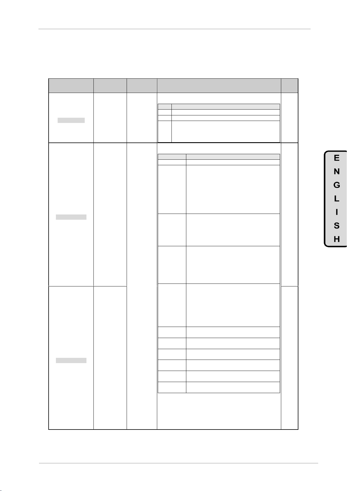
POWER ELECTRONICS
SD500
PROGRAMMING PARAMETER DESCRIPTION
31
Screen / Default Value
Name /
Description
Range
Function
Set on
RUN
1 OP FLT RLY= 0X0
Operate flt rely
G8.1.1 / Relay
Output due to
Fault
000 to XXX
This parameter allows setting when will the relay output enable
configured as [29 FAULT]:
BIT
FUNCTION
00X
Fault due to Low Voltage
0X0
Fault excluding Low Voltage cause.
X00
Final automatic restart fault. The relay will enable whenever
all of the restarting trials have been carried out, which have
been set in parameter [G12.1 ‘Retry Num’] or the time set in
parameter [G12.2 ‘Retry Dly’] has elapsed.
YES
2 RLY1= Trip
Function Relay 1
G8.1.2 / Relay 1
Control Source
Selection
NONE
FDT-1
FDT-2
FDT-3
FDT-4
OVERLOAD
IOL
UNDRLOAD
VENTWARN
OVERVOLT
LOWVOLT
OVERHEAT
RUN
STOP
STEADY
SPD SRCH
READY
PUMP
TRIP
ENCODER DIR
COMPARAT
BRCTRL
Configures each relay and digital output according to the options of the
following table:
OPTION
FUNCTION
NONE
The output has no effect.
FDT-1
In order to check when the output frequency has
reached the defined frequency by the user. The
relay will enable whenever the following equation is
satisfied:
OutputF>frequency – ([G9.2 ′FDTBnd′] / 2).
Example: If the reference frequency is 50Hz and
[G9.2 ‘FDTBnd’]=10Hz, then 50 – (10/2)=45Hz. The
contactwill close with frequencies greater than
45Hz.
FDT-2
The relay is active whenever the frequency
reference is set [G9.1 ′FDTLvl′] being [G9.2
‘FDTBnd’] the bandwidth.
For example: If the frequency value is 40Hz, [G9.1
′FDTLvl′]=40Hz and [G9.2 ‘FDTBnd’]=4Hz, the
contact will close from 38Hz to 42Hz.
FDT-3
The relay will enable with frequencies from
[G9.1 ‘FDTLvl’] – ([G9.2 ‘FDTBnd’]/2) to [G9.1
‘FDTLvl’] + ([G9.2 ‘FDTBnd’]/2).
For example: If [G9.1 ‘FDTLvl’]=30Hz and [G9.2
‘FDTBnd’]=10Hz, then the contact will close from
(30 – (10/2)) to (30 + (10/2)). This means, from
25Hz to 35Hz during acceleration.
FDT-4
The relay will be active whenever the output
frequency is greater than the [G9.1 ‘FDTLvl’] value
and remains closed until it decreases under [G9.1
‘FDTLvl’] – ([G9.2 ‘FDTBnd’]/2).
For Example: If [G9.1 ‘FDTLvl’]=30Hz and [G9.2
‘FDTBnd’]=10Hz, then the contact will close with
values greater than 30Hz and it will not open until it
decreases under 25Hz.
OVERLOAD
The relay will be active when the motor is in
overload.
IOL
The relay will be active in case a fault due to
overload protection occurs.
UNDRLOAD
The relay will be active in case of an underload
warning.
VENTWARN
The relay will be active in case a fan fault occurs, if
parameter [G11.27 FANTrip] is set as ‘WARN’.
OVERVOLT
The relay will enable whenever the drives DC bus
voltage is greater than the protection voltage.
LOWVOLT
The relay will enable whenever the drives bus DC
voltage is lower than the protection voltage.
Note: Continues on next page.
SI
3 RLE2= Run
Function Relay 2
G8.1.3 / Relay 2
Control Source
Selection
YES
4.8. Group 8 – G8: Outputs
4.8.1. Subgroup 8.1 – S8.1: Digital O/P

SD500
POWER ELECTRONICS
32
PROGRAMMING PARAMETER DESCRIPTION
Screen / Default
Value
Name / Description
Range
Function
Set on
RUN
4 DOP1= FDT-1
Digital Output1
G8.1.4 / Digital
Output 1 Control
Source Selection
NONE
FDT-1
FDT-2
FDT-3
FDT-4
OVERLOAD
IOL
UNDRLOAD
VENTWARN
OVERVOLT
LOWVOLT
OVERHEAT
RUN
STOP
STEADY
SPD SRCH
READY
PUMP
TRIP
ENCODER DIR
COMPARAT
BRCTRL
Note: Previous page continuation.
OPTION
FUNCTION
OVERHEAT
The relay will enable if the cooling fan is out of service.
RUN
The relay will enable with the start command. However,
it will not enable during the DC brake.
STOP
The relay will enable whenever no start command has
been sent and no output voltage is present within the
drive.
STEADY
The relay will enable when the drive operates at
constant speed.
SPD SRCH
The relay will be enabled whenever the drive is in
search speed mode. For further information, check
subgroup [G7.18 ‘Speed Search’].
READY
The relay will enable whenever the drive is ready to
start (without any warnings or trips).
PUMP
Used to configure an auxiliary fixed pump in the pump
programme.
TRIP
The relay will enable due to a trip, according to
parameter [G8.1.1 ‘OP FLT RLY’].
ENCODER
DIR (*)
It is a warning of the encoder. The relay will be active
when the encoder is misplaced.
COMPARAT
The relay will enable whenever the setting conditions
found in [Group 9: ‘Comparators’] are satisfied.
BRCTRL
Used to control the brake opening. See group [G17:
External Brake’].
YES
5 T RL ON= 0.00s
Delay Dig O/P On
G8.1.5 / DO1 and
Relays Connection
Delay
0 to 100.00s
The user is able to specify a delay in the relays and digital output 1
connections. If during the connection delay time the activation condition
disappears, the relay will not enable.
YES
6 T RL OF= 0.00s
Dely Dig I/P Off
G8.1.6 / DO1 and
Relays
Disconnection delay
0 to 100.00s
The user is able to specify a delay within the digital output 1 and relays
disconnection. If during the disconnection delay time, the disable condition
disappears, the relay will not disable.
YES
7 INV NA/NC= 000
Logic NC/NO Rlys
G8.1.7 / Digital
Output and Relay
Contact Type
Selection
000 to XXX
Defines the type of contact following this order: Digital Output 1, Relay 2
and Relay 1, from left to right according to the bit assignment:
BIT
FUNCTION
0
Contact normally open (NO)
X
Contact normally closed (NC)
NO
(*) Available if parameter G19.1.1 =VECTOR

POWER ELECTRONICS
SD500
PROGRAMMING PARAMETER DESCRIPTION
33
Screen / Default Value
Name /
Description
Range
Function
Set on
RUN
1 A01= Frequency
AO1 Mode
G8.2.1 / Analog
Output 1 Selection
Mode
Frequency
O/ pCurr
O/pVolt
DCLinkV
O/p Power
TargetFq
RampFreq
PIDRefVal
PIDFdbVal
PIDO/p
Constant
The analog output 1 is programmable according to the following table:
DESCR.
FUNCTION
Frequency
Signal proportional to the motor speed. For the
maximum frequency defined in [G10.1 - MsSpL] a 10V
voltage will be present
O/ pCurr
Signal proportional to the motor current. 10V are
generated when the drive rated current is at 200%.
O/pVolt
Signal proportional to the motor voltage. For the
voltage value defined in [G2.2.4 ′MTR VOLT′] a 10V
voltage will be present.
DCLinkV
Signal proportional to the bus DC voltage. The
analogue output is 10V when the DC voltage is
410Vdc for 220Vac drives and 820Vdc for 400Vac
drives.
O/p Power
Signal proportional to the output power.
10V are generated operating 200% of the nominal
power.
TargetFq
Signal proportional to the target frequency set in the
drive.
RampFreq
Sign proportional to the frequency which has executed
the acceleration and deceleration functions and it can
be different to the real output frequency.
PIDRefVal
PID reference value signal. Generates 6,6V working to
the 100% of the reference.
PIDFdbVal
Sign proportional to the feedback in PID mode.
Generates 6,6V at 100% of the reference value.
PIDO/p
Signal proportional to the PID controller output value.
Generates 5V at 100% of the reference value.
Constant
[G8.2.5 ′SA1Con′] value
NO
2 AO1Ga= +100.0%
AO1 Gain
G8.2.2 / Analog
Output 1 Gain
-1000.0
to
1000.0%
These parameters allow adjusting the gain and offset level of the
analogue output 1. If a current signal is desired, the set value will be 20%
For example, when the analogue output is configured as ‘Frequency’, the
equation that governs the operation is:
where Gain AO1 is set in parameter [G8.2.2 AO1Ga] and Offset
AO1 is set in parameter [G8.2.3 AO1Ofst].
YES
3 AO1Ofst= +0.0%
AO1Bias
G8.2.3 / Analog
Output 1Offset
Level
-100.0
to
100.0%
YES
4 AO1OFil = 5ms
AO1 Filter
G8.2.4 / Analog
Output 1 Filter
Selection
0 to 10000ms
Filter for the analog output 1 value.
Occasionally, the analog signal is slightly unstable. It can be improved
selecting another filter value.
Note: The use of a filter can add a slight delay within the analog output
YES
5 AO1Con= 0.0%
AO1 Constant Set
G8.2.5 / Analog
Output 1
Constant Value
0 to 1000.0%
Allows the setting of the constant speed found in the analog output 1,
whenever it has been configured as ‘Constant’ in parameter [G8.2.1
‘AO1’].
YES
6 AO2= Frequency
AO2 Set
G8.2.6 / Analog
Output 2 Mode
Selection
Frequency
O/ pCurr
O/pVolt
DCLinkV
O/p Power
TargetFq
RampFreq
PIDRefVal
PIDFdbVal
PIDO/p
Constant
The analog output 2 is programmable according to the following table:
DESCR.
FUNCTION
Frequency
Signal proportional to the motor speed. For the
maximum frequency defined in [G10.1 - MsSpL] a
20mA current will be present
O/ pCurr
Signal proportional to the motor current. 20mA are
generated when the drive rated current is at 200%.
O/pVolt
Signal proportional to the motor voltage. For the
voltage value defined in [G2.2.4 ′MTR VOLT′] a 20mA
current will be present.
DCLinkV
Signal proportional to the bus DC voltage. The
analogue output is 20mA when the DC voltage is
410Vdc for 220Vac drives and 820Vdc for 400Vac
drives.
Note: Continues on next page.
YES
4.8.2. Subgroup 8.2 – S8.2: Analog O/P

SD500
POWER ELECTRONICS
34
PROGRAMMING PARAMETER DESCRIPTION
Screen / Default Value
Name /
Description
Range
Function
Set on
RUN
6 AO2= Frequency
AO2 Set
G8.2.6 / Analog
Output 2 Mode
Selection
Frequency
O/ pCurr
O/pVolt
DCLinkV
O/p Power
TargetFq
RampFreq
PIDRefVal
PIDFdbVal
PIDO/p
Constant
Note: Previous page continuation.
DESCR.
FUNCTION
O/p Power
Signal proportional to the output power.
20mA are generated operating 200% of the nominal
power.
TargetFq
Signal proportional to the target frequency set in the
drive.
RampFreq
Sign proportional to the frequency which has executed
the acceleration and deceleration functions and it can
be different to the real output frequency.
PIDRefVal
PID reference value signal. Generates 13,2mA
working to the 100% of the reference.
PIDFdbVal
Sign proportional to the feedback in PID mode.
Generates 13,2mA at 100% of the reference value.
PIDO/p
Signal proportional to the PID controller output value.
Generates 13,2mA at 100% of the reference value.
Constant
[G8.2.5 ′SA1Con′] value
YES
7 OA2Ga= +100.0%
AO2 Gain
G8.2.7 / Analog
Output 2 Gain
-1000.0
to
1000.0%
These parameters allow adjusting the gain and offset level of the
analogue output 2. If a current signal is desired, the set value will be 20%.
For example, when the analogue output is configured as ‘Frequency’, the
equation that governs the operation is:
where Gain AO2 is set in parameter [G8.2.7 AO2Ga] and Offset
AO2 is set in parameter [G8.2.8 AO2Ofst].
YES
8 AO2Ofst= +20.0%
AO2 Bias
G8.2.8 / Analog
Output Offset
Level
-100 to 100%
YES
9 AO2Fil= 5ms
AO2 Filter
G8.2.9 / Analog
Output 2 Filter
Selection
0 to 10000ms
Filter for the analog output 2 value.
Occasionally, the analog signal is slightly unstable. It can be improved
selecting another filter value.
Note: The use of a filter can add a slight delay within the analog output
YES
10 AO2Con= 0.0%
AO2 Const Set
G8.2.10 / Analog
Output 2 Constant
Value
0 to 1000%
Set the constant current values found in the analog output 2, whenever it
is set as ‘Constant’ in parameter [G8.2.6 ‘AO2’].
YES
Screen / Default Value
Name /
Description
Range
Function
Set on
RUN
1 FDTLvl= 30.00Hz
Relay FDT level
G9.1 / Transfer
Function Level
0 to
[G10.1]Hz
Set the reference frequency level for the comparator. See options ‘FDT1’, ‘FDT-2’, ‘FDT-3’ and ‘FDT4’ in parameters subgroup [S8.1 DIGITAL
O/P].
YES
2 FDTBnd= 10.00Hz
Relay FDT band
G9.2 / Transfer
Function
Bandwidth
0 to
[G10.1]Hz
Set the bandwidth according to the frequency defined in parameter [G9.1
′FDTLvl′].
See options ‘FDT-1’, ‘FDT-2’, ‘FDT-3’ and ‘FDT4’ in parameters group
[S8.1 ‘Digital O/P’].
YES
3 SLCOM= None
Selec sourc comp
G9.3 / Comparator
Source Selection
None
AI1
AI2
AI3
AI4
The comparator source can be set according to the following table:
OPTION
FUNCTION
None
There is no source for the comparator
AI1
Analog input 1 will be used as source by the comparator.
AI2
Analog input 2 will be used as source by the comparator.
AI3
Analog input 3 will be used as source by the comparator.
Note: This option is only available whenever the I/O
Expansion Board has been installed.
AI4
Analog input 4 will be used as source by the comparator.
Note: This option is only available whenever the I/O
Expansion Board has been installed.
Note: Whenever an unavailable option is selected, the parameter will
return to the previously selected option.
NO
4 S C ON= +90.00%
Setpoint On comp
G9.4 / Output
Activation Level in
Comparator Mode
10 to 100%
In order to define the level to compare with the source selected in
parameter [G9.3 ′SLCOM′]. In case this level is over passed, one of the
digital outputs adjusted as ‘COMPARAT’ in [S8.1 DIGITAL O/P] will
enable. See parameters [G8.1.2 RLY1] to [G8.1.4 DOP1].
NO
5 S C OF= +10.00%
Setpoint Off Comp
G9.5 / Output
Deactivation Level
in Comparator
Mode
-100 to
adjusted level
in [G9.4 S C
ON]
In order to define the level to compare with the source selected in
parameter [G9.3 ′SLCOM′]. In case this level is over passed, one of the
digital outputs adjusted as ‘COMPARAT’ in [S8.1 DIGITAL O/P] will
enable. See parameters [G8.1.2 RLY1] to [G8.1.4 DOP1].
NO
4.9. Group 9 – G9: Comparators

POWER ELECTRONICS
SD500
PROGRAMMING PARAMETER DESCRIPTION
35
Screen / Default Value
Name /
Description
Range
Function
Set on
RUN
1 MxSpL= 50.00Hz
Max Speed Lt
G10.1 / Maximum
Speed Limit
40 to
400.00Hz
In order to set the maximum speed limit that the drive can apply to the
motor. If a value above this limit is received, the drive will ignore it and will
take the limit value.
Note: Enabling the PID or the PUMP programme in parameter [G1.3
PROG], the units will be % instead of Hz. Furthermore, the default value
will change from 50Hz to 100%.
NO
2 FWR/RV= None
Prevention Rotat
G10.2 / Speed
Inverting
Permission
None
FWDPrev
RevPrev
Inverting the motor speed is possible. This function helps to prevent the
motor from rotating in inverse direction.
OPT.
FUNCTION
None
The motor spins in both directions.
FWDPrev
Motor can not rotate clockwise.
RevPrev
Motor can not rotate anti clockwise.
YES
3 UseFrqLimit= Y
Use Freq Limit
G10.3 / Frequency
Limit N Y
Enable or disable the frequency limit
OPT.
FUNCTION
N=NO
Frequency limit disabled.
Y=YES
Frequency limit enabled.
NO
4FqLtLo= 0.50Hz
Freq Limit Lo
G10.4 / Lower
Frequency Limit
0 to [G10.5
FqLtHi]
Set the lower frequency limit if parameter is set as [UseFrqLimit= S]
YES
5 FqLtHi= 50.00Hz
Freq Limit Hi
G10.5 / Upper
Frequency Limit
0.5 to [G10.1
MxSpL]
Set the upper frequency limit whenever the parameter is set as
[UseFrqLimit= S]
NO
6 TORQUE LIMIT= N (*)
Torque Limit
G10.6 / Torque
Limit Activation
N
Y
In order to enable or disable the torque limit applied to the load.
OPT.
FUNCTION
N=NO
Torque limit disabled.
Y=YES
Torque limit enabled.
NO
7 LvTrqLt= 180%
[1]
(*)
Level Torq Limit
G10.7 / Torque
Limit Level
30 to 250%
Keeps the maximum torque adjusted value, preventing a greater value
from being applied. This parameter unit is %, in reference to the motor
nominal torque.
NO
Screen / Default Value
Name /
Description
Range
Function
Set on
RUN
1 TqLimRef = LOCAL
G10.8.1 / Torque
lim Ref
LOCAL
AI1
AI2
AI3
AI4
MDBUS
ENCOD
COMMS
PLC
The user is able to select the source to introduce the torque limit
reference.
OPTION
FUNCTION
LOCAL
Reference will be introduced through keyboard and
will be adjusted in G10.8.2, G10.8.3, G10.8.4 and
G10.8.5.
AI1
The reference will be introduced through the analog
input 1
AI2
The reference will be introduced through the analog
input 2
AI3
The reference will be introduced through the analog
input 3
AI4
The reference will be introduced through the analog
input 4
MDBUS
The reference will be introduced through Modbus
ENCOD
The reference will be taken from the encoder
COMMS
The reference will be introduced through the
communications
PLC
The reference will be introduced through PLC
NO
2 TLposFW = 180%
G10.8.2 / Tq lim
positiv FW
0 to 200%
The user can set the forward motoring operation torque limit whenever
the torque limit reference has been set as LOCAL
YES
3 TLnegFW = 180%
G10.8.3 / Tq lim
negatv FW
0 to 200%
The user can set the forward regeneration operation torque limit
whenever the torque limit reference has been set as LOCAL
YES
4 TLposRV = 180%
G10.8.4 / Tq lim
positiv RV
0 to 200%
The user can set the reverse motoring operation torque limit whenever
the torque limit reference has been set as LOCAL
YES
5 TLnegRV = 180%
G10.8.5 / Tq lim
negatv RV
0 to 200%
The user can set the reverse regeneration operation torque limit
whenever the torque limit reference has been set as LOCAL
YES
4.10. Group 10 – G10: Limits
[1]
Available whenever [G10.6 TORQUE LIMIT] =Y.
(*) Hidden if parameter G19.1.1 =VECTOR
4.10.1. Subgroup 10.8 – S10.8 : Vector Lim (*)
(*) Available if parameter G19.1.1 = VECTOR

SD500
POWER ELECTRONICS
36
PROGRAMMING PARAMETER DESCRIPTION
Screen / Default Value
Name /
Description
Range
Function
Set on
RUN
6 TqOffRf = LOCAL
G10.8.6 / Tq offset
Ref
LOCAL
AI1
AI2
AI3
AI4
MDBUS
COMMS
PLC
The user is able to select the source to introduce the torque offset
reference.
OPTION
FUNCTION
LOCAL
Reference will be introduced through keyboard and
will be adjusted in G10.8.7 and G10.8.8
AI1
The reference will be introduced through the analog
input 1
AI2
The reference will be introduced through the analog
input 2
AI3
The reference will be introduced through the analog
input 3
AI4
The reference will be introduced through the analog
input 4
MDBUS
The reference will be introduced through Modbus
COMMS
The reference will be introduced through the
communications
PLC
The reference will be introduced through PLC
NO
7 TqOfLO = 0 %
G10.8.7 / LOCAL
Ref OffTq
-120 to 120%
The user can set the torque offset whenever the torque offset reference
has been set as LOCAL
YES
8 TqOfcmp = 0 %
G10.8.8 / Tq
compens offst
0 to 100%
The user can set the compensation torque offset whenever the torque
offset reference has been set as LOCAL
YES
9 SpLimRf = LOCAL
G10.8.9 / Speed
Lim Ref
LOCAL
AI1
AI2
AI3
AI4
MDBUS
COMMS
PLC
The user is able to select the source to introduce the speed limit
reference
OPTION
FUNCTION
LOCAL
Reference will be introduced through keyboard and
will be adjusted in G10.8.10 and G10.8.11
AI1
The reference will be introduced through the analog
input 1
AI2
The reference will be introduced through the analog
input 2
AI3
The reference will be introduced through the analog
input 3
AI4
The reference will be introduced through the analog
input 4
MDBUS
The reference will be introduced through Modbus
COMMS
The reference will be introduced through the
communications
PLC
The reference will be introduced through PLC
NO
10 SpL (+) = 50 Hz
G10.8.10 / Speed
Lim FW
0 to [G10.5]
and [G10.1]
The user can set the forward speed limit whenever the speed limit
reference has been set as LOCAL
YES
11 SpL (-) = 50 Hz
G10.8.11 / Speed
Lim REV
0 to [G10.5]
and [G10.1]
The user can set the reverse speed limit whenever the speed limit
reference has been set as LOCAL
YES
12 SpLGa = 500 %
G10.8.12 / Speed
Lim Gain
100 to 5000%
Set how much the speed reference has to decrease when motor speed
exceeds the speed limit.
YES

POWER ELECTRONICS
SD500
PROGRAMMING PARAMETER DESCRIPTION
37
Screen / Default Value
Name /
Description
Range
Function
Set on
RUN
1 RIRLs= None
ResponIf_REF_Ls
G11.1 /
Response in case
of a Speed
Reference Loss
None
FreeRun
Dec
Hold I/P
Hold O/P
LostPrst
The drive will carry out one of the following actions when losing a speed
reference:
OPT.
FUNCTION
None
Protection is disabled.
FreeRun
The drive cuts the output voltage and allows the motor
free run.
Dec
A deceleration until stop is produced in the time defined
in parameter [G5.15 ′FltDecT′]
Hold I/P
The drive will keep operating to the input value, mean
value obtained from the last 10 seconds until the
moment the reference los has been detected.
Hold /P
The drive will keep operating to the input value, mean
value obtained from the last 10 seconds until the
moment the reference loss has been detected
LostPrst
The drive operates to the frequency defined in
parameter [G11.4 ′RfLRf′]
Caution: Users should ensure that disabling this
protection does not compromise the operation of the
installation and/or equipment.
SI
3 RfLsDly= 1.0s
Ref Loss Dly
G11.3 / Trip Delay
Time Due to
Speed Reference
Loss
0.1 to 120s
Delay time setting after which the speed reference loss protection will
enable.
YES
4 RefLRf= 0.00Hz
Ref Loss Ref
G11.4 / Speed in
case of Reference
Loss
[G19.2.5] to
[G10.1] (Hz)
In order to set the frequency value at which the drive will operate in case
a speed reference loss occurs. Therefore, the parameter [G11.1 ′RIRLs′]
must be set to the value ‘LostPrst’.
YES
5 OLWarnSel= NO
OL Warn Select
G11.5 / Overload
Warning
NO
YES
In order to enable/disable the overload protection. The relay output or
digital output used for enabling the warning must be configured as
‘OverLoad’. See subgroup [S8.1 DIGITAL O/P], parameters [G8.1.2
RLY1] to [G8.1.4 DOP1].
OPTION
FUNCTION
NO
Overload warning disabled.
YES
Overload warning enabled.
YES
6 OLWrnL= +150%
OL Warn Level
G11.6 / Overload
Warning Level
30 to 200%
The overload warning is a combination of the parameters [G11.5], [G11.6]
and [G11.7]. The drive will enable some of the digital outputs configured
as ‘OverLoad’ whenever the current flowing within the motor is greater
than the value defined in parameter [G11.6 OLWrnL′] during the time
established in parameter [G11.7 ′OLWrnT′].
YES
7 OLWrnT= 10.0s
OL Warn Time
G11.7 / Delay
Time for Enabling
the Overload
Warning
0 to 30.0s
YES
8 OLTS= FreeRun
OL Trip Select
G11.8 / Action
Selection due to
Overload Fault
None
FreeRun
Dec
The drive will carry out the following actions in case an overload fault
occurs:
OPTION
FUNCTION
None
Protection is disabled.
FreeRun
The drives output is cut, having as a consequence the
motor free run.
Dec
A deceleration until stop is produced in the time defined
in parameter [G5.15 ′FltDecT′]
Caution: Users should ensure that disabling this
protection does not compromise the operation of the
installation and/or equipment.
YES
9 OLLevel= 180%
Overload Level
G11.9 / Trip Level
in case of
Overload Fault
30 to 200%
The overload warning protection is a combination of the parameters
[G11.8], [G11.9] and [G11.10]. The drive will carry out the action selected
in parameter [G11.8 ′OLTS′] whenever the current flow within the motor is
greater than the parameter [G11.9 ′OLLevel’] value during the time
defined in parameter [G11.10 ′ETH1minnTFllSC′].
YES
10 OLTrpT= 60.0s
OL Trip Time
G11.10 / Delay
Time for in case of
Trip due to
Overload Fault
0 to 60.0s
YES
11 ETH1min= +150%
ETH 1 min
G11.11 /
Overcurrent Level
During 1 Minute
120 to 200%
The user is able to set the current level which flows continuously during
one minute in % referenced to the motor nominal current. The motor
nominal current is set in parameter [G2.1.2 MTR CUR]. Whenever this
limit is over passed, the thermo-electronic protection will be enabled, and
the action defined in parameter [G11.13 ‘ThMM] will be executed.
YES
4.11. Group 11 – G11: Protections

SD500
POWER ELECTRONICS
38
PROGRAMMING PARAMETER DESCRIPTION
Screen / Default Value
Name /
Description
Range
Function
Set on
RUN
12 ETHcont== 120%
ETH Cont Rating
G11.12 /
Continuous
Overcurrent Level
50 to 200%
This parameter sets the overcurrent level under which the drive is able to
work without enabling the thermo-electronic protection.
YES
13 ThMM= None
ThermModelMode
G11.13 / Action
Selection in case
of Thermoelectronic Fault
None
FreeRun
Dec
The drive will carry out one of the following actions in café of a motor
thermo-electronic fault:
OPTION
FUNTION
None
Protection is disabled.
FreeRun
The drives output is cut which allows the motor free run
Dec
A deceleration until stop is produced in the time defined
in parameter [G5.15 ′FltDecT′]
Caution: Users should ensure that disabling this
protection does not compromise the operation of the
installation and/or equipment.
YES
14 EnableUL= NO
Enable UL
G11.14 / Enabling
Underload
Warning
NO
YES
Enabling or disabling the warning in case of underload. The relay output
or digital output used for enabling the warning must be configured as
‘UndrLoad’. See subgroup [S8.1 DIGITAL O/P], parameters [G8.1.2
RLY1] to [G8.1.4 DOP1].
OPTION
FUNTION
N=NO
Underload warning disabled.
Y=YES
Underload warning enabled.
YES
15 ULWnDI= 10.0s
UL Warn Dly
G11.15 / Delay
Time Enabling
Underload
Warning
0 to 600.0s
Delay time set when enabling the underload warning. The drive will wait
this time before enabling the warning.
YES
16 ULFM= None
UL Fault Mode
G11.16 / Action
Selection in case
of Underload Fault
None
FreeRun
Dec
The drive will carry out one of the following actions in case of underload
fault:
OPTION
FUNCTION
None
Protection is disabled.
FreeRun
The drives output is cut, having as a consequence the
motor free run.
Dec
A deceleration until stop is produced in the time defined
in parameter [G5.15 ′FltDecT′]
Caution: Users should ensure that disabling this
protection does not compromise the operation of the
installation and/or equipment.
YES
17 ULFltDI= 30.0s
UL Fault Dly
G11.17 / Delay
Time Enabling
Underload Fault
0 to 600.0s
Delay time set enabling the underload protection fault. The drive will wait
this time before enabling the protection fault.
YES
18 UlMnL = +30%
UL Min Level
G11.18 /
Underload
Detection Lower
Level
10
to
[G11.19]
In order to set the underload lower level limit when the drive is in normal
duty (Variable Torque). The protection will be enabled if the current is
below the value adjusted in this parameter when the operating frequency
is twice the motor rated slip speed.
Note: The motor rated slip speed is set in parameter [G19.2.6 RtSlip] and
the type of load can be set in parameter [G19.2.9 ‘Load Duty’].
YES
19 ULMxL= +30%
UL Max Level
G11.19 /
Underload
Detection Upper
Level
[G11.18]
to
100%
This parameter sets the upper limit in order to detect the underload when
the drive is in normal duty (Variable Torque). The protection will be
enabled if the current is below the value adjusted in this parameter when
the operating frequency is equal to the motor rated frequency.
When the drive is in heavy duty (Constant Torque), the protection will be
enabled if the current is below the value adjusted in this parameter at any
operating frequency.
Note: The type of load can be set in parameter [G19.2.9 ‘Load Duty’].
YES
20 NoMD= None
NoMotorDetect
G11.20 / Action
Selection in case
of No Motor
Connection
Detected Fault
None
FreeRun
The drive will carry out one of the following actions whenever a fault is
present due to the fact that no motor has been connected to the drives
output terminal:
OPTION
FUNCTION
None
Protection is disabled.
FreeRun
The drives output is cut, having as a consequence the
motor free run.
Caution: Users should ensure that disabling this
protection does not compromise the operation of the
installation and/or equipment.
YES
21 NoMtrLvl= +5%
No Motor Level
G11.21 / Trip
Level in case of
No Motor
Detection Fault.
1 to 100%
The fault protection due to not detecting a motor is a combination of the
following parameters [G11.20], [G11.21] and [G11.22]. The drive will
carry out an action selected in parameter [G11.20 ′NoMD′] whenever the
current flowing within the motor does not exceed the value defined in
parameter [G11.21′NoMtrLvl′] during the time defined in parameter
[G11.22 ′NoMtrDl′].
YES
22 NoMtrDl= 3.0s
No Motor Dly
G11.22 / Delay
Time due to Lack
of motor Fault
0.1 to 10.0s
YES

POWER ELECTRONICS
SD500
PROGRAMMING PARAMETER DESCRIPTION
39
Screen / Default Value
Name /
Description
Range
Function
Set on
RUN
23 OvHM= None
Overheat Mode
G11.23 / Selection
in case of Motor
Overheat Fault
None
FreeRun
Dec
In order to enable this protection, it is necessary to connect the PTC
thermistor and select the analogue input where it is connected in
parameter [G11.24 ‘OvrHtSen’] or select the digital input from [G4.1.3] to
[G4.1.10] set as ‘ThermalIn’.
The drive will carry out one of the following actions in case of motor
overheat fault:
OPTION
FUNCTION
None
No action is carried out
FreeRun
The drives output is cut, having as a consequence the
motor free run.
Dec
A deceleration until stop is produced in the time defined
in parameter [G5.15 ′FltDecT′]
Caution: Users should ensure that disabling this
protection does not compromise the operation of the
installation and/or equipment.
YES
24 OvrHtSen= None
Overheat Sensor
G11.24 / Motor
Overheat
Detection Sensor
Selection
None
AI1
AI2
AI3
AI4
The user is able to select the type of analog input which will be used to
connect the PTC thermisor. For further information related to the PTC
thermistor, read SD500 Hardware and Installation Manual.
OPTION
FUNCTION
None
No connection
AI1
Analog input 1 is used, setting the PTC thermisor by
voltage.
AI2
Analog input 2 is used, setting the PTC thermisor by
current.
AI3
Analog input 3 is used, setting the PTC thermisor by
voltage.
Note: This option is only available whenever the I/O
expansion board has been installed.
AI4
Analog input 4 is used, setting the PTC thermisor by
current.
Note: This option is only available whenever the I/O
expansion board has been installed.
Note: Whenever an unavailable option is selected, the parameter will
return to the previously selected option.
NO
25 OvrHtL= +50.0%
Overheat Level
G11.25 / Motor
Overheat
Detection Fault
0 to 100%
In order to set the PTC thermistor level. For Analog Input 1(Voltage), the
100% corresponds to 10V. For Analog Input 2 (Current), the 100%
corresponds to 5V (Current converted into voltage through PTC).
For example, if the AI2 is used and this parameter is set to 50%, the
protection will be enabled if the applied voltage to AI2 is less than 2,5V.
YES
26 OvrHtAr= Low
Overheat Area
G11.26 / Trip Area
Selection Due to
Overheat.
LOW
HIGH
The overtemperature protection function can be enabled according to the
following table:
OPTION
FUNCTION
LOW
Trips whenever the voltage present in the analog input is
under the value set in parameter [‘G.11.25 OvrHtL’]
HIGH
Trips whenever the voltage present in the analog input
exceeds the value set in parameter [‘G.11.25 OvrHtL’].
YES
27 FANTrip=Trip
FAN Trip Mode
G11.27 / Action
Selection in case
of Fan Trip
Trip
Warn
In order to select the action to carry out in case a fault within the cooling
fan is detected:
OPTION
FUNCTION
Trip
The drive generates a Fan-trip.
Warn
The drive will enable the relay configured as
‘VentWarn’.
YES
28 DBWarnED= +0%
[1]
DB Res Warn Lvl
G11.28 / Brake
Unit Overload
Warning Level
0 to 30%
In order to set the overload warning level within the brake unit in an
operative cycle. The braking resistor can be used during 15 seconds.
After that, the drive will disable the output relay configured as
‘DBOvrLoad’.
YES
29 LSS PH= NONE
Lss Phase Type
G11.29 / Phase
loss Detection
NONE
OUTPUT
INPUT
ALL
The user is able to enable or disable the protection when detecting a
phase loss:
OPT.
FUNCTION
NONE
Phase loss protection disabled.
OUTPUT
Output phase loss protection enabled.
INPUT
Input phase loss protection enabled. For its correct
operation, the user should set the parameter G11.30.
ALL
Input and output phase loss protection enabled. For its
correct operation, the user should set the parameter
G11.30.
Caution: Users should ensure that disabling this
protection does not compromise the operation of the
installation and/or equipment.
NO
[1] This parameter is only present in drives under 22kW.

SD500
POWER ELECTRONICS
40
PROGRAMMING PARAMETER DESCRIPTION
Screen / Default Value
Name /
Description
Range
Function
Set on
RUN
30 Ripple V=40V
Ripple Voltage
G11.30 / DC Bus
Ripple voltage
1 to 100V
In order to set the DC Bus ripple voltage that must be exceeded to get a
phase loss phase input fault when G11.29 is set as “INPUT” or “ALL”.
This value is set following customer’s requirements.
YES
31 GND Fault Level=
20%
GND Fault Level
G11.31 / GND
Fault Level
0 to 100%
Set ground fault threshold. Default value is 20%.
YES
32 GND Fault Tout= 30
ms
GND Fault Tout
G11.32 / GND
Fault Tout
0 to 250 ms
Allows adjusting the timeout in case the threshold defined for ground fault
(G11.31) is exceeded. Default timeout is 30 ms.
YES
Screen / Default Value
Name /
Description
Range
Function
Set on
RUN
1 Retry NUm= 0
Retry Number
G12.1 / Auto Reset
Number of Trials
0 to 10
This parameter allows the setting of the number of reset trials, which the
drive will carry out in case a fault occurs. This parameter and [‘G12.2
RetryDly’] one must force the drive to execute the auto reset function
safely.
In order to start the motor after executing a reset caused by a fault, the
parameter [G7.11 ‘ST Aft Rst’] must be configured as ‘Yes’.
YES
2 Retry Dly= 1.0s
Retry Delay
G12.2 / Delay Time
before Auto Reset
0 to 60.0s
This parameter sets the time elapsed between a fault and rearming. After
this time has elapsed, if the fault condition is still active, the drive will
disable the auto-reset function and will remain in fault status.
YES
Screen / Default Value
Name /
Description
Range
Function
Set on
RUN
No Fault
G13.1 /Current
Fault status
visualization
-
This screen will be automatically displayed every time the drive trips with
a new fault.
Shows the current fault status of the drive. In case there is no fault the
screen will display the message ‘No Fault’. By pressing the ‘*’ key the
fault number will be displayed.
The drive resets pressing the display STOP-RESET key or using an
external reset when available. Faults can be automatically reset using the
Auto Reset function. See parameter group [G12 ′Auto Reset′].
The following table shows all of the possible faults:
COD
FAULT
COD
FAULT
0
No Fault
20
FAN Trip
1
OverLoad
21
RESERVED
2
UnderLoad
22
Param_Wr_Err
3
Inv OverLoad
23
Pipe Fill Flt
4
E-Thermal
24
IO Board Fail
5
Ground Fault
25
External Brake
6
Output Ph Loss
26
No Motor
7
Input Ph Loss
27
Slot 1 Fail
8
OverSpeed
28
Slot 2 Fail
10
NTC
29
Slot 3 Fail
11
OverCurrent
33
Free Run
12
OverVoltage
34
Low Voltage
13
External Trip
35
Lost Command
14
Short ARM
36
KeypadLostCMD
15
OverHeat
49
ADC Error
16
Fuse Open
50
EEPROM
17
MC Fail
51
Watchdog-1 Err
18
Encoder Error
52
Watchdog-2 Err
19
PTC
Note: For further information about faults see section ‘6. FAULT
MESSAGES. DESCRIPTION AND ACTIONS’.
-
4.12. Group 12 – G12: Auto Reset
4.13. Group 13 – G13: Faults History

POWER ELECTRONICS
SD500
PROGRAMMING PARAMETER DESCRIPTION
41
Screen / Default Value
Name /
Description
Range
Function
Set on
RUN
FAULT 1 INFO
[1]
G13.2 / Fault
History Register 1
-
The first group called [FAULT INFO 1] shows the information of the last
fault and will be used as the first fault history register.
The last five faults, listed in chronological order, are shown as new faults
occur, with the most recent fault in the first place [FAULT INFO 1]. Every
time a fault is produced, the drive shows the [FAULT INFO 1] screen,
moving the previous fault to the next register position [FAULT INFO 2].
The rest of stored faults will move down a position. The oldest fault
message [FAULT INFO 5] will be lost.
These groups enable accessing to the extended information of every one
of the last five faults registers. This information displays the drive status in
the moment the fault has been produced.
OPT.
FUNCTION
X Fault=
Fault register X display
X Op Fq=
Output frequency value when fault occurred.
X Out I=
Output current value when fault occurred
X DC Volt=
Bus voltage value when fault occurred
X Temp=
Equipments temperature when fault occurred.
X DI=
Digital input s status values when fault
occurred.
X DO Sta=
Digital outputs status values when fault
occurred
X On Days=
Number of days the equipment has been
turned on until fault.
X On Min=
Number of minutes the equipment has been
turned on until fault.
X RUN Days=
Number of days the equipment has been
running until fault.
X RUN Min=
Number of minutes the equipment has been
running until fault.
-
FAULT 2 INFO
[1]
G13.3 / Fault
History Register 2
-
-
FAULT 3 INFO
[1]
G13.4 / Fault
History Register 3
-
-
FAULT 4 INFO
[1]
G13.5 / Fault
History Register 4
-
-
FAULT 5 INFO
[1]
G13.6 / Fault
History Register 5
-
-
Clr FaultHist= N
ClearFLTHistory
G13.7 / Clear
Fault History
N
Y
OPT.
FUNCTION
N=NO
Function disabled.
Y=YES
Deletes the fault history (the last five faults). The screen
will return to the default value ‘NO’ once all of the faults
have been deleted.
YES
ENB/DIS LV Flt= D
Enb/Dis LV Fault
G13.8 / Low
Voltage fault
register
D
E
In order to select if Low Voltage fault must be saved in the fault history
register or not.
OPT.
FUNCTION
D=DISABLED
The Low Voltage fault will not be saved in the fault
history.
E=ENABLED
The Low Voltage fault will be saved in the fault
history.
Note: If the drive losses power completely before displaying the fault, the
Low Voltage fault will not be saved despite having enabled this
parameter.
YES
[1] These groups will be displayed as new faults are produced.

SD500
POWER ELECTRONICS
42
PROGRAMMING PARAMETER DESCRIPTION
Screen / Default Value
Name /
Description
Range
Function
Set on
RUN
1 MREF 1= 10.00Hz
Multi-Reference 1
G14.1 / Multi-
Reference 1
[G19.2.5] to
[G10.1]
The user is able to set multiple references for the drive. This will be
enabled by the use of the digital inputs configured as speed multireferences.
In order to proceed with their use, firstly, the operating mode must be
selected:
STANDARD mode:
Set option ‘STANDARD’ in parameter [G1.3 PROG]. Then, the digital
inputs that control the multi-references should be selected, being set as
SPEED-L, SPEED-M, SPEED-H and SPEED-X.
The adjustment is carried out by assigning a speed value for every
parameter within this group, from [G14.1] to [G14.15].
The following table links the digital inputs configured as SPEED to the
selected multi-reference:
PARM
REF
DIGITAL. O: SPEED
X H M L G14.1
MREF 1
0 0 0
X
G14.2
MREF 2
0 0 X
0
G14.3
MREF 3
0 0 X X G14.4
MREF 4
0 X 0
0
G14.5
MREF 5
0 X 0
X
G14.6
MREF 6
0 X X 0 G14.7
MREF 7
0 X X
X
G14.8
MREF 8
X 0 0
0
G14.9
MREF 9
X 0 0 X G14.10
MRF 10
X 0 X
0
G14.11
MRF 11
X 0 X
X
G14.12
MRF 12
X X 0 0 G14.13
MRF 13
X X 0
X
G14.14
MRF 14
X X X
0
G14.15
MRF 15
X X X
X
Note: 0: Inactive and X: Active.
PID mode:
Set option ‘PID’ in parameter [G1.3 PROG]. Then, the digital inputs DI6,
DI7 and DI8 must be selected, setting these digital inputs as MRefPID-H,
MRefPID-M and MRefPID-L respectively. The adjustment is carried out
by assigning a value (in %) for every parameter from [G14.1] to [G14.7].
The following table links the digital inputs configured as MRefPID to the
selected multi-reference:
PARM
REF
DIGITAL. O: MRefPID
H M L
G14.1
MREF 1 0 0 X G14.2
MREF 2 0 X
0
G14.3
MREF 3 0 X
X
G14.4
MREF 4 X 0 0 G14.5
MREF 5 X 0
X
G14.6
MREF 6 X X
0
G14.7
MREF 7 X X
X
Note: 0: Inactive and X: Active.
YES
2 MREF 2= 20.00Hz
Multi-Reference2
G14.2 / Multi-
Reference 2
3 MREF 3= 30.00Hz
Multi-Reference3
G14.3 / Multi-
Reference 3
4 MREF 4= 40.00Hz
M Multi-Reference4
G14.4 / Multi-
Reference 4
5 MREF 5= 50.00Hz
Multi-Reference5
G14.5 / Multi-
Reference 5
6 MREF 6= 50.00Hz
Multi-Reference6
G14.6 / Multi-
Reference 6
7 MREF 7= 50.00Hz
Multi-Reference7
G14.7 / Multi-
Reference 7
8 MREF 8= 50.00Hz
Multi-Reference8
G14.8 / Multi-
Reference 8
9 MREF 9= 50.00Hz
Multi-Reference9
G14.9 / Multi-
Reference 9
10 MRF 10= 45.00Hz
Multi-Reference10
G14.10 / Multi-
Reference 10
11 MRF 11= 40.00Hz
Multi-Reference11
G14.11 / Multi-
Reference 11
12 MRF 12= 35.00Hz
Multi-Reference12
G14.12 / Multi-
Reference 12
13 MRF 13= 25.00Hz
Multi-Reference13
G14.13 / Multi-
Reference 13
14 MRF 14= 15.00Hz
Multi-Reference14
G14.14 / Multi-
Reference 14
15 MRF 15= 5.00Hz
Multi-Reference15
G14.15 / Multi-
Reference 15
4.14. Group 14 – G14: Multi-references

POWER ELECTRONICS
SD500
PROGRAMMING PARAMETER DESCRIPTION
43
Screen / Default Value
Name /
Description
Range
Function
Set on
RUN
1 InchFq= 10.00Hz
Inch Frequency
G15.1 / Inch
Frequency
0.5 to [G10.1]
This parameter allows the setting of the motor inch frequency. The inch
frequency selection can be executed through a digital input. Therefore,
the digital input used should have been configured as ‘INCH1’. See
[G4.1.3] to [4.1.10] parameters. Enabling the inch frequency prevails over
the rest of multi-reference inputs.
YES
2 InchAcT= 20.0s
INCH Acc Timer
G15.2 / Inch
Frequency
Accelerating Time
0 to 600.0s
In order to set the time in which the drive accelerates to reach the inch
speed.
YES
3 InchDeT= 30.0s
INCH Dec Time
G15.3 / Inch
Frequency
Decelerating Time
0 to 600.0s
In order to set the time in which the drive decelerates to reach the inch
frequency.
YES
Screen / Default Value
Name /
Description
Range
Function
Set on
RUN
1 Jmp Freq= NO
Jump Frequency
G16.1 / Enabling
Frequency Jumps
NO
YES
The user is able to enable or disable a band of jump frequencies to avoid
resonance frequencies or other frequency types that the motor will avoid
as references. The drive will pass these frequencies during the speed
changes (acceleration and/or deceleration) but will not operate within
these values.
OPT.
FUNCTION
NO
In order to disable the frequency jump function
YES
In order to enable the frequency jump function
NO
2 JmpLo1= 10.00Hz
Jump Low 1
G16.2 / Frequency
Jump 1 Lower
Limit
0 to [G16.3]
Allows setting the frequency jump 1 lower limit.
YES
3 JmpHi1= 15.00Hz
Jump High 1
G16.3 / Frequency
Jump 1 Upper
Limit
[G16.2] to
[G10.1]
Allows setting the frequency jump 1 upper limit.
YES
4 JmpLo2= 20.00Hz
Jump Low 2
G16.4 / Frequency
Jump 2 Lower
Limit
0 to [G16.5]
Allows setting the frequency jump 2 lower limit.
YES
5 JmpHi2= 25.00Hz
Jump High 2
G16.5 / Frequency
Jump 2 Upper
Limit
[G16.4] to
[G10.1]
Allows setting the frequency jump 2 upper limit.
YES
6 JmpLo3= 30.00Hz
Jump Low 3
G16.6 / Frequency
Jump 3 Lower
Limit
0 to [G16.7]
Allows setting the frequency jump 3 lower limit.
YES
7 JmpHi3= 35.00Hz
Jump High 3
G16.7 / Frequency
Jump 3 Upper
Limit
[G16.6] to
[G10.1]
Allows setting the frequency jump 3 upper limit.
YES
4.15. Group 15 – G15: Inch Speeds
4.16. Group 16 – G16: Frequency Jumps

SD500
POWER ELECTRONICS
44
PROGRAMMING PARAMETER DESCRIPTION
Screen / Default Value
Name /
Description
Range
Function
Set on
RUN
1 RIsCurr= 50.0%
Brake Open Curr
G17.1 / Opening
Brake Current
0 to 180.0%
This parameter is able to set the brake current opening of the relay
configured as ‘BRCtrl’. See parameter [G8.1 – DIGITAL I/O] subgroup.
YES
2 RlsDly= 1.00s
Brake Open Delay
G17.2 /Opening
Brake Delay
0 to 10.00s
Once the motor current is greater than the one set in this parameter
[G17.1 ‘RlsCurr’] and the frequency reached in the motor is the same as
the one set in parameter [G17.3 ‘FwdFrq’]. The drive will open the relay
configured as ‘BRCtrl’ and will keep this speed during the time
established in this parameter.
NO
3 FwdFrq= 1.00Hz
BrakeOpenFWDFrq
G17.3 / Opening
Brake Frequency
(Foward)
0 to 400.00Hz
In order to set the brake opening frequency of the relay configured as
‘BRCtrl’ while the motor is accelerating in positive direction.
NO
4 RevFrq= 1.00Hz
BrakeOpenRevFrq
G17.4 / Opening
Brake Frequency
(Reverse)
0 to 400.00Hz
In order to set the brake opening frequency of the relay configured as
‘BRCtrl’ while the motor is accelerating in negative direction.
NO
5 BrEngFr= 1.00s
Brake Close Dly
G17.5 / Closed
Brake Delay
0 to 10.00s
Once the motor has reached the frequency set in [G17.6 ‘BrEngFr’], the
drive will close the braking relay and will keep this speed during the time
established in this parameter.
NO
6 BrEngFr= 2.00Hz
Brake Close Freq
G17.6 / Closed
Brake Frequency
0 to 400.00Hz
In order to set the frequency value at which the braking relay will stop
operating, allowing the closed brake function.
NO
Screen / Default Value
Name /
Description
Range
Function
Set on
RUN
1 EncMode = None
G18.1 / Encoder
Function
None
FBK
REF
Select the encoder function:
OPTION
FONCTION
None
The encoder function is not active
FBK
The encoder is used as feedback
REF
The encoder is used as reference
YES
2 Type = LineDrive
G18.2 / Encoder
Type Select
LineDrive
Totem/Com
Open Coll
Select signal delivery method of encoder.
NO
3 Pulse = (A+B)
G18.3 / Encoder
Pulse Select
(A+B)
-(A+B)
(A)
Set the way of encoder pulse.
OPTION
FONCTION
(A+B)
Forward operation
-(A+B)
Reverse operation
(A)
Only one channel is used
NO
4 PulseNum = 1024
G18.4 / Number of
Encoder Pulses
10 to 4096
Set the number of pulses per rotation
NO
5 EncMo = 0 Hz
G18.5 / Feedback
Monitor
-300 to 300
Hz
Shows the encoder speed in terms of motor frequency.
YES
6 Pulse Monitor = 0 kHz
G18.6 / Ref
Monitor
-200 to 200
kHz
Shows the encoder speed in terms of encoder pulses.
YES
7 Filter = 3 ms
G18.7 / Encoder
I/P Filter
0 to 10000ms
Set the time constant of the encoder filter.
YES
8 X1 = 0 kHz
G18.8 / Encoder
IP Min Pulse
0 to [G18.10]
Set the minimum number of pulses in harmony with the encoder
specification in kHz.
YES
9 Y1 = 0 %
G18.9 / Perc.
Encoder Min
Pulse
0 to 100%
Set the minimum frequency of the input enconder.
YES
4.17. Group 17 – G17: External Brake
4.18. Group 18 – G18: ENCODER

POWER ELECTRONICS
SD500
PROGRAMMING PARAMETER DESCRIPTION
45
Screen / Default Value
Name /
Description
Range
Function
Set on
RUN
10 X2 = 100 kHz
G18.10 /Encoder
IP Max Pulse
[G18.8] to
200 kHz
Set the maximum number of pulses in harmony with the encoder
specification in kHz.
YES
11 Y2 = 100%
G18.11 / Perc
Encoder Max
Pulse
0 to 100%
Set the maximum frequency of the input encoder.
YES
12 WireChk = N
G18.12 / Encoder
option connection
check
N
Y
Set if you want to check or not the state of enconder connection.
OPTION
FUNCTION
N
Enconder connection won’t be checked
Y
Enconder connection will be checked
YES
13 ChTim = 1s
G18.13 / Encoder
Connection Check
Time
0.1 to 1000s
Set the time during which check is being done.
YES
Screen / Default Value
Name /
Description
Range
Function
Set on
RUN
1 CTRL T.= V/Hz
Control Type
G19.1.1 / Control
Type Selection
V/Hz
SlipCom
S-less1
VECTOR
This selection determines the drives control type.
OPT.
FUNCTION
V/Hz
Scalar control mode, where control is carried out
applying to the motor a voltage/frequency ramp.
SlipCom
Whenever this function is active, it compensates the
slip produced in the motor. In case a heavy load
capable of producing a big slip during the start, set
the parameter as ‘SlipCom’. This option can be
adjusted with parameters [G19.2.1 ‘InertiaRate’] and
[G19.2.6 ‘RtSlip’].
S-less1
This function applies a vector control without encoder.
VECTOR(*)
This function applies a vector control with encoder.
NO
2 FREQ= 2.0kHz
[1]
Modulat Frequenc
G19.1.2 /
Modulation
Frequency
From 0.7 to
15kHz
[2]
Varies the commutation frequency in the motor output stage, reducing the
noise within the motor.
[2]
The modulation frequency range depends on the drive capacity which
is shown in the following table:
POWER
MODULATION FREQ.
Up to 22kW
From 0.7 to 15kHz
From 30 to 45kW
From 0.7 to 10kHz
From 55 to 75kW
From 0.7 to 7kHZ
YES
3 V/FPn= Linear
V/F Pattern
G19.1.3 / V/F
Pattern
Linear
Square
V/F Us
The user is able to set the alternative acceleration ramp.
OPTION
FUNCTION
Linear
Output voltage increases and decreases at constant
rate proportional to voltage/frequency (V/F) relation.
Used in order to achieve a constant torque load
regardless of the frequency.
Square
Output voltage increases quadratically according to the
frequency.
V/F Us
This parameter defines a V/F pattern customised by the
user. The voltage and frequency settings are carried out
in parameter [G19.1.4 ‘V/F USER’] subgroup.
NO
4 Torque CTRL(*) = N
G19.1.4 / Speed
or Torque Control
N
Y
The user is able to set the control mode:
OPTION
FUNCTION
NO
Speed control is selected
YES
Torque control is selected
NO
4.19. Group 19 – G19: Fine Setting
4.19.1. Subgroup 19.1 – S19.1: IGBT Control
[1]
Value that depends on the drive rated current.
(*) Available if parameter G19.1.1 =VECTOR

SD500
POWER ELECTRONICS
46
PROGRAMMING PARAMETER DESCRIPTION
Screen / Default Value
Name /
Description
Range
Function
Set on
RUN
5 Auto Tuning =
NONE(*)
G19.1.5 / Auto
tunning
None
All
Allst
Rs+Lsig
Enc test
Tr
Set the type of auto tuning:
OPTION
FUNCTION
None
Auto-tunning is not active
All
The motor parameters are measured with the motor
rotating. The stator resistance (Rs), leak inductance
(Lσ), stator inductance (Ls), no-load current and rotor
time constant are all measured. The encoder state is
also measured. The encoder related functions should
be rightly set. If load is connected to the motor axis, the
parameter might not be correctly measured so remove
the load before measurement.
Allst
Motor parameters are measured when the motor is
stopped. Stator resistance (Rs), leak inductance (Lσ)
and rotor time constant are measured at the same time.
Rs+Lsig
The parameter is measured when the motor is not
operating. The measured values are used for auto
torque boost and sensorless vector control.
Enc test
When the encoder optional card is connected, the motor
checks connection and misconnection of A and B
pulses. The encoder related functions should be rightly
set.
Tr
If the drive operates with a vector control, the motor
measures the rotor time constant while rotating. If the
drive operates with sensorless control, the motor
measures the rotor time constant while being static.
NO
Screen / Default Value
Name /
Description
Range
Function
Set on
RUN
1 UsFrq1= 15.00Hz
User Frequency 1
G19.1.4.1 / User
Frequency 1
0 to [G10.1]
In order to set the user frequency 1. The drive will provide at this
frequency value the voltage set in parameter [G19.1.4.2 User V1].
NO
2 User V1= 25%
User Voltage 1
G19.1.4.2 / User
Voltage 1
0 to 100%
In order to set the user voltage 1. The drive will provide at this voltage
value the frequency set in parameter [G19.1.4.1 UsFrq1].
NO
3 UsFrq2= 30.00Hz
User Frequency 2
G19.1.4.3 / User
Frequency 2
0 to [G10.1]
In order to set the user frequency 2. The drive will provide at this
frequency value the voltage set in parameter [G19.1.4.4 User V2].
NO
4 User V2= 50%
User Voltage 2
G19.1.4.4 / User
Voltage 2
0 to 100%
In order to set the user voltage 2. The drive will provide at this voltage
value the frequency set in parameter [G19.1.4.3 UsFrq2].
NO
5 Us Frq3= 45.00Hz
User Frequency 3
G19.1.4.5 / User
Frequency 3
0 to [G10.1]
In order to set the user frequency 3. The drive will provide at this
frequency value the voltage set in parameter [G19.1.4.6 User V3].
NO
6 User V3= 75%
User Voltage 3
G19.1.4.6 / User
Voltage 3
0 to 100%
In order to set the user voltage 3. The drive will provide at this voltage
value the frequency set in parameter [G19.1.4.5 UsFrq3].
NO
7 Us Frq4= 60.00Hz
User Frequency 4
G19.1.4.7 / User
Frequency 4
0 to [G10.1]
In order to set the user frequency 4. The drive will provide at this
frequency value the voltage set in parameter [G19.1.4.8 User V4].
NO
8 User V4= 100%
User Voltage 4
G19.1.4.8 / User
Voltage 4
0 to 100%
In order to set the user voltage 4. The drive will provide at this voltage
value the frequency set in parameter [G19.1.4.7 UsFrq4].
NO
(*) Available if parameter G19.1.1 =VECTOR
4.19.1.1.1. Subgroup 19.1.4 – S19.1.4 V/F USER Pattern

POWER ELECTRONICS
SD500
PROGRAMMING PARAMETER DESCRIPTION
47
Screen / Default Value
Name /
Description
Range
Function
Set on
RUN
1 InertiaRate= 0
[1]
Inertia Rate
19.2.1 / Inertia
Range
0 to 8
In order to select the inertia load according to the motor inertia value:
OPT.
FUNCTION
0
Smaller than 10 times the motor inertia
1
10 times greater than the motor inertia.
2 a 8
More than 10 times greater than the motor inertia value.
NO
2 T Boost= Manual
Torque Boost
G19.2.2 / Initial
Voltage
MANUAL
AUTO
Proportional to the initial voltage value applied to the motor in the start
moment to overcome the resisting torque in heavy starts.
OPT.
DESCRIPTION
FUNCTION
0
MANUAL
Starting voltage manual setting by the
use of parameters [G19.2.3 ′FWBoost′]
and [G19.2.4 ′RVBoost′].
1
AUTO
The drive calculates automatically the
voltage to apply at the start using the
motor parameters.
NO
3 FWBoost= +20%
Fwd Boost
G19.2.3 / Starting
Torque (Foward
Direction)
0 to 150%
This parameter sets the intensified torque in forward direction
NO
4 RVBoost= +20%
Rev Boost
G19.2.4 / Starting
Torque (Reverse
Direction)
0 to 150%
This parameter sets the intensified torque in reverse direction
NO
5 STR FRQ= 0.50Hz
Start Freq
G19.2.5 / Starting
Frequency
0.01 to 10Hz
The Initial frequency which will be applied when the drive starts is set.
NO
6 RtSlip= 45rpm
[1]
Rated Slip
G19.2.6 / Slip
Compensation
0 to 3000rpm
This function, when enabled, compensates the motor slip. When facing a
heavy load capable of producing a big slip during the start, configure this
parameter.
Note: The value of this parameter will be automatically configured when
setting parameter [G2.2.1 MOTRPWR].
NO
7 FLUX MIN= NONE
Minimum Flux Mod
G19.2.7 /
Minimum Flux
NONE
MANU
AUTO
In order to set the minimum flux that the motor can employ to operate
under low load conditions. With this optimised flux system, noises and
power losses will be reduced due to the automatic flux level arrangement.
The following table shows the different configurations available:
OPTION
FUNCTION
NONE
No action is executed
MANU
Selects the manual mode. If the output current is
lower than the parameter [G2.1.3 ′NOLOADC′] (motor
no load current), output voltage will be reduced in its
magnitude set in parameter [G19.2.8 ′FLUX LVEL′]
AUTO
Selects the automatic mode. The output voltage is set
taking into account the motor rated current set in
[G2.1.2’MTR CUR’] and the no load current
[G2.1.3 ′NOLOADC’]
NO
8 FLUX LVEL= +0%
Nv Flj min mnual
G19.2.8 / Manual
Mode Minimum
Flux Value
0 a 30%
In order to set the output voltage reducing magnitude if parameter
[G19.2.7 ‘FLUX MIN] is set in manual mode ‘MANU’.
YES
9 Load Duty= Hevy
Load Duty Type
G19.2.9 / Load
Type Definition
NRML
HEVY
Selects the applied load type:
OPTION
FUNCTION
NRML
Selects the normal load type (variable torque) for
applications such as fans or pumps
HEVY
Selects the heavy load type (constant torque) for
applications such as elevators and cranes.
NO
4.19.2. Subgroup 19.2 – S19.2: Motor Load
[1]
This value depends on the motor rated current.

SD500
POWER ELECTRONICS
48
PROGRAMMING PARAMETER DESCRIPTION
Screen / Default Value
Name /
Description
Range
Function
Set on
RUN
1 Rs=
Stator Resistor
G19.3.1 / Stator
Resistor (Rs)
*
Stator resistor fine setting.
NO
2 LSigma=
Leak Inductor
G19.3.2 / Leak
Inductor
*
Leak inductor fine setting.
NO
3 Ls=
Stator Inductor
G19.3.3 / Stator
Inductor
*
Inductor stator fine setting.
NO
4 Tr=
Rotor Time Const
G19.3.4 / Rotor
Time Constant
25 to 5000ms
Rotor time constant fine setting.
NO
5 ASR P1 = 50 % (*)
G19.3.5 / Vector
Gain Prop. 1
10 to 500%
Set the proportional gain 1 of the speed controller (ASR). The higher the
proportional gain, the faster the response will be. But if the gain is too
high, the speed of the motor might oscillate.
YES
6 ASR I1 = 300 ms (*)
G19.3.6 / Vector
Integral Time 1
10 to 9999ms
Set the integral gain 1 of the speed controller (ASR).
YES
7 ASR P2 = 50 % (*)
G19.3.7 / Vector
Gain Prop. 2
10 to 500%
Set the proportional gain 2 of a separate controller. The higher the
proportional gain, the faster the response will be. But if the gain is too
high, the speed of the motor might oscillate.
YES
8 ASR I2 = 300 ms (*)
G19.3.8 / Vector
Integral Time 2
10 to 9999ms
Set the integral gain 2 of a separate controller.
YES
9 SwASR = 0 Hz (*)
G19.3.9 / Switch
G ASR
0 to 120Hz
Set the gain change frequency between gain 1 and gain 2.
YES
10 dlASR = 0.10 s (*)
G19.3.10 / Delay
Switch ASR
0 to 100s
The gain of the speed controller changes from gain 1 to gain 2 after this
time if one of the digital inputs is configured as ASR GAIN 2.
YES
11 RASRf = 0 ms (*)
G19.3.11 / Filter
Ref. ASR
0 to 20000ms
Set the time constant of the speed controller reference filter in the vector
speed mode.
YES
12 OurFVec = 0 ms (*)
G19.3.12 / Out
Filter Vector
0 to 2000ms
Set the time constant of the speed controller reference filter in the vector
speed mode and set the time constant of the torque command filter in the
vector torque mode.
YES
Screen / Default Value
Name /
Description
Range
Function
Set on
RUN
1ComUpdate= NO
Comm Update
G20.1.1 /
Communication
Update
NO
YES
This parameter enables the possibility of reconnecting communications
when a parameter has been changed. For example, the communication
speed, frame definition, etc.
YES
2 Slave Addr= 1
Int485 SlaveAddr
G20.1.2 /
Communication
Address
1 to 250
Identifier assigned to the drive to communicate with from the network.
When communicating with several equipments, each one of them should
be assigned to a different address.
YES
3 Prot= ModBus
Int485 Protocol
G20.1.3 / Int485
Communication
Protocol
MODBUS
Select the type of protocol used in communications:
OPTION
FUNCTION
MODBUS
Protocol compatible with MODBUS-RTU.
YES
4 BaudR= 9600 bps
Int485 BautRate
G20.1.4 /
Communication
Speed
1200
2400
4800
9600
19200
38400
This parameter establishes the data transfer speed. It sets the Modbus
communications transfer rate which must match with the bus
communication master within the drive.
YES
4.19.3. Subgroup 19.3 – S19.3: Motor Model
* This value depends on the motor.
(*) Available if parameter G19.1.1 =VECTOR
4.20. Group 20 – G20: Communication Buses
4.20.1. Subgroup 20.1 – S20.1: Int485 Protocol

POWER ELECTRONICS
SD500
PROGRAMMING PARAMETER DESCRIPTION
49
Screen / Default Value
Name /
Description
Range
Function
Set on
RUN
5 Mode= D8/PN/S1
Int485 Mode
G20.1.5 /
Communication
Frame Definition
D8/PN/S1
D8/PN/S2
D8/PE/S1
D8/PO/S1
Select the communication frame composition and defines the data length,
parity confirmation method and the number of stop bits:
OPTION
FUNCTION
D8/PN/S1
8 bits Data / Without parity check / 1 stop bit
D8/PN/S2
8 bits Data / Without parity check / 2 stop bit
D8/PE/S1
8 bits Data / Even numbers parity check / 1
stop bit
D8/PO/S1
8 bits Data / Odd numbers parity check / 1
stop bit
YES
6RespDly= 5ms
Response Delay
G20.1.6 / Transfer
Delay After
Reception
0 to 1000ms
The MODBUS-RTU communication plays the role of the slave device.
The slave will respond the master after a period of time set in this
parameter. This allows the master device to attend to the
communications within a system where the master can not manage a
quick slave answer.
YES
7 ParamSave= NO
Comm Param Save
G20.1.7 / Saving
Communication
Parameters
NO
YES
The communication parameters are stored in the RAM, lost when the
drive is switched off. This parameter stores the information of the rest of
communication parameters, kept in the memory although the drive has
been switched off.
NO
Screen / Default Value
Name /
Description
Range
Function
Set on
RUN
1 MREF1= 10.00%
Mult-Reference1
G25.1.1 / PID
Local Reference 1
[G19.2.5] to
[G10.1]
When working with a single local reference in PID mode, the value will be
set in [G25.1.1. ′MREF1′]
The speed applied in each situation will depend on the digital inputs
enabling status configured with the following options:
[G4.1.8 DI6 = ′MRefPID-H′]
[G4.1.9 DI7 = ′MRefPID-M′]
[G4.1.10 DI8 = ′MRefPID-L′]
Assignment is executed according to the following table:
DIGITAL INPUTS
PID REFERENCE
DI6=00
DI7=00
DI=00
0 0 X
G25.1.1 ‘M_Ref1’
0 X 0
G25.1.2 ‘M_Ref2’
0 X X
G25.1.3 ‘M_Ref3’
X 0 0
G25.1.4 ‘M_Ref4’
X 0 X
G25.1.5 ‘M_Ref5’
X X 0
G25.1.6 ‘M_Ref6’
X X X
G25.1.7 ‘M_Ref7’
YES
2 MREF2= +20.00%
Mult-Reference2
G25.1.2 / PID
Local Reference 2
YES
3 MREF3= +30.00%
Mult-Reference3
G25.1.3 / PID
Local Reference 3
YES
4 MREF4= +40.00%
Mult-Reference4
G25.1.4 / PID
Local Reference 4
YES
5 MREF5= +50.00%
Mult-Reference5
G25.1.5 / PID
Local Reference 5
YES
6 MREF6= +50.00%
Mult-Reference6
G25.1.6 / PID
Local Reference 6
YES
7 MREF7= +50.00%
Mult-Reference7
G25.1.7 / PID
Local Reference 7
YES
4.21. Group 25 – G25: Pump Control
The [G25: ‘Pump Control’] only appears if the [G1.3 PROG=’PUMP’] parameter has been selected.
4.21.1. Subgroup 25.1 – S25.1: System Setpoint

SD500
POWER ELECTRONICS
50
PROGRAMMING PARAMETER DESCRIPTION
Screen / Default Value
Name /
Description
Range
Function
Set on
RUN
1 PIDSetp= MREF
PID Setpoint
G25.2.1 / PID
Setpoint Source
MREF
AI1
AI2
AI3
AI4
MODBUS
COMMS
PLC
The user can select the source to introduce the PID regulator set point.
OPTION
FUNCTION
MREF
PID set point introduced from keypad. The different set
point values are set in the [G25.1: ‘System Setpoint]’.
AI1
PID set point introduced by the analog input 1.
AI2
PID set point introduced by the analog input 2
AI3
PID set point introduced by the analog input 3
Note: This option will be only available whenever the I/O
expansion board has been installed.
AI4
PID set point introduced by the analog input 4
Note: This option will be only available whenever the I/O
expansion board has been installed.
MODBUS
PID set point introduced through the Modbus
communications found within the drive.
COMMS
PID set point introduced through any of the optional
communication boards.
Note: This option will be only available whenever any of
the optional communication boards have been installed.
PLC
PID set point introduced through the equipments PLC.
Note: This option will be only available whenever any of
the optional communication boards have been installed.
Note: In case an unavailable option is selected, the parameter will return
to the previously selected option.
NO
2 PID Fbk= AI2
PID Feedback
G25.2.2 / PID
Feedback Source
MREF
AI1
AI2
AI3
AI4
MODBUS
COMMS
PLC
Selecting the source through which the feedback signal will be introduced
to close the control loop.
OPTION
FUNCTION
AI1
Feedback signal through analog input 1.
AI2
Feedback signal through analog input 2.
AI3
Feedback signal through analog input 3
Note: This option will be only available whenever the I/O
expansion board has been installed.
AI4
Feedback signal through analog input 4
Note: This option will be only available whenever the I/O
expansion board has been installed
MODBUS
Feedback signal through Modbus communications
integrated in the drive.
COMMS
Feedback signal through any optional communication
boards.
Note: This option will be only available whenever any of
the optional communication boards have been installed.
PLC
Feedback signal through the equipments PLC.
Note: This option will be only available whenever any of
the optional communication boards have been installed.
Note: In case an unavailable option is selected, the parameter will return
to the previously selected option.
NO
3 PID Kc= +50.0%
Proportional PID
G25.2.3 / PID
Regulator
Proportional Gain
0 to 1000.0%
In order to set the regulators proportional gain according to the
installations requirements. Whenever a greater control response is
required, increase this value.
Note: Increasing excessively this value may introduce a major instability
within the system.
YES
4 PID It= 10.0s
Integral PID
G25.2.4 / PID
Regulator
Integrating Time
0 to 200.0s
In order to set the regulator integrating time according to the installation
requirements. Whenever a greater precision is required, increase this
value.
Note: Increasing this value excessively, may slow down the system.
YES
5 PID Dt= 0.0s
Differential PID
G25.2.5 / Pid
Regulator
Differential Time
0 to
1000.0ms
Setting the regulator differential time. If a major response is required,
increase this value.
Note: Increasing excessively this value may decrease precision
Note: Usually is recommended not to set this value, due to the fact that
its default value is 0.0 s, adequate for the pump control applications.
YES
6 MxSL= +50.00Hz
Max Speed LIM
G25.2.6 / PID
Frequency Upper
Limit
[G25.2.7] to
300.00Hz
In order to set the PID output upper limit.
YES
7 MnSL= 0.00Hz
Min Speed LIM
G25.2.7 / PID
Frequency Lower
Limit
300 to
[G25.2.6] Hz
In order to set the PID output lower limit.
YES
4.21.2. Subgroup 25.2 – S25.2: PID

POWER ELECTRONICS
SD500
PROGRAMMING PARAMETER DESCRIPTION
51
Screen / Default Value
Name /
Description
Range
Function
Set on
RUN
8 InvertPID= N
PID Out Inv
G25.2.8 / PID
Output Inverting
NO
YES
The user is able to invert the PID output.
OPTION
FUNCTION
NO
The PID regulator answers in normal mode.
Therefore, when the feedback value exceeds the
reference signal, it will decrease its speed. However,
if the feedback is lower than the reference signal
value, the speed will be increased.
YES
The PID regulator answers in inverse mode.
Therefore, when the feedback exceeds the reference
signal, speed will be increased. However, when the
feedback value is lower than the reference signal, the
speed will be decreased.
NO
9 Out Sc= +100.0%
Out Scale
G25.2.9 / PID
Output Scale
0.1 to
1000.0%
In order to set the PID regulator output magnitude.
NO
Screen / Default Value
Name /
Description
Range
Function
Set on
RUN
1 LP Pon= 35%
Awakening Level
G25.3.1 /
Awakening Level
0 to 100%
This parameter sets the resuming PID control level after a suspension
period (sleep mode).
YES
2 FP1Son= 49.99Hz
Fix Pmp1 Str Spd
G25.3.2 / Fix
Pump 1 Starting
Speed
0 to
[G10.1]Hz
In order to set the starting speed o the fix pumps. To start the pumps
successfully, the following conditions must be satisfied:
- Main motor speed exceeds the value set in parameters
[G25.3.2] to [G25.3.5].
-Time set in parameter [G25.3.6 ′FP Ton′] has passed.
- The difference between the reference signal and the PID
controller is greater than the error signal set in parameter
[G25.4.8 ′FP Error’]
YES
3 FP2Son = 49.99Hz
Fix Pmp2 Str Spd
G25.3.3 / Fix
Pump 2 Starting
Speed
0 to
[G10.1]Hz
4 FP3Son = 49.99Hz
Fix Pmp3 Str Spd
G25.3.4 / Fix
Pump 3 Starting
Speed
0 to
[G10.1]Hz
5 FP4Son = 49.99Hz
Fix Pmp4 Str Spd
G25.3.5 / Fix
Pump 4 Starting
Speed
0 to
[G10.1]Hz
6 FP Ton= 60.0s
Fix Pump Str Dly
G25.3.6/ Fix
Pumps Starting
Delay
0 to 3600s
In order to set the time delay within the fix pumps start.
Note: If the times are too short, they might generate overpressures within
the network. Excessive times will generate under pressures within the
network.
YES
Screen / Default Value
Name /
Description
Range
Function
Set on
RUN
1 LP T Slpr= 60.0s
Drive Sleep Dely
G25.4.1 / Delay
Before Enabling
Sleep Mode
0 to 999.0s
This parameter sets the delay time for enabling the sleep mode. If the
drive operates at a speed value under the one established in parameter
[G25.4.2], it will stop running and it will enter in sleep mode.
YES
2 Slp Spd= 0.00Hz
Dr Sleep Speed
G25.4.2 / Enabling
Sleep Mode
Speed
0 to [G10.1]
The user can set the speed under which if a time period greater than the
one defined in parameter [G25.4.1], the drive will stop operating and
enter in sleep mode.
YES
3 SPD1of= 15.0Hz
FPump1 Stp Speed
G25.4.3 / Fix
Pump 1 Stopping
Speed
0 to
[G10.1]Hz
In order to set the speed to stop the fix pumps. In order to produce the
stop of the fix pumps, the following conditions should be satisfied:
- The main pump speed decreases under the value set in
parameters [G25.4.3] to [G25.4.6].
- Time, set in parameter [G25.4.7 ′FP Tof′] has passed.
- The difference between the reference signal and the PID
controller feedback is lower than the error signal set in parameter
[G25.4.8 ′FP Error′]
YES
4 SPD2of = 15.0Hz
FPump2 Stp Speed
G25.4.4 / Fix
Pump 2 Stopping
Speed
0 to
[G10.1]Hz
5 SPD3of = 15.0Hz
FPump3 Stp Speed
G25.4.5 / Fix
Pump 3 Stopping
Speed
0 to
[G10.1]Hz
6 SPD4of = 15.0Hz
FPump4 Stp Speed
G25.4.6 / Fix
Pump 4 Stopping
Speed
0 to
[G10.1]Hz
7 Fp Tof= 60.0s
FPump Stp Delay
G25.4.7 / Stopping
Fix Pump Delay
0 to 3600s
Fix pumps stopping delay setting
YES
8 FP Error= 2%
FPmp Str/Stp Err
G25.4.8 / PID
Maximum Error
Stopping Fix
Pumps
0 to 100%
PID error under which the fix pumps will stop
YES
4.21.3. Subgroup 25.3 – S25.3: Start Conditions
4.21.4. Subgroup 25.4 – S25.4: Stop Conditions

SD500
POWER ELECTRONICS
52
PROGRAMMING PARAMETER DESCRIPTION
Screen / Default Value
Name /
Description
Range
Function
Set on
RUN
1 AccTime= 2.0s
Aux Accl Time
G25.5.1 / Main
Motor Accelerating
Time after Fix
Pump Stop
0 to 600.0s
In order to set the main motor accelerating time after a fix pump has been
disabled. Set 0.1s to deactivate this option.
YES
2 Dec Timel= 2.0s
Aux Decl Time
G25.5.2/ Main
Motor Accelerating
Time after Fix
Pump Activation
0 to 600.0s
In order to set the main motor decelerating time after a fix pump has been
enabled.
YES
Screen / Default Value
Name /
Description
Range
Function
Set on
RUN
1 Fill Sp= 0.00Hz
Pipe filling Spd
G25.7.1 / Filling
Pipes Speed
0 to [G10.1]
This parameter sets the speed reference during a pipe filling period.
During this period, acceleration is carried out without PID control
NO
2 Fill P= 0.0%
PFill end Pressu
G25.7.2 / Filling
Pipes Pressure
0 to 100%
This parameter determines when has the filling pipes process conclude
by setting the pressure of the filling pipes ending value. The PID mode
will start if the PID controller feedback is greater than the value defined in
this parameter.
NO
3 Fill Tim= 600s
PFill End Delay
G25.7.3 / Filling
Pipes Delay
0 to 9999s
If a lower value defined in [G25.7.2] parameter during a longer time
period than the one defined in this parameter, a ‘Pipe Fill Flt’ will take
place.
YES
Screen / Default Value
Name /
Description
Range
Function
Set on
RUN
1 First FP= 1
First Start.FP
G25.9.1 / First
Fixed Pump
Selection
1 to 4
Select the fixed pumps controlled by the drive which will run in first place
For Example:
If there are 3 fixed pumps controlled by Relay 1, Relay 2 and Digital
Output 1 and this parameter is set as ‘2’, the operating sequence will be
Relay2Digital Output 1Relay 1
NO
2 FP number= 0
Number Fixed Pmp
G25.9.2 / Number
of Fixed Pumps
Selection
0 to 4
In order to set the number of fixed pumps controlled by the drive
NO
4.21.5. Subgroup 25.5 – S25.5: Speed Bypass
4.21.6. Subgroup 25.7 – S25.7: Filling Pipes
4.21.7. Subgroup 25.9 – S25.9: Enable Pump

POWER ELECTRONICS
SD500
MODBUS COMMUNICATION
53
5. MODBUS COMMUNICATION
5.1. Introduction
The drive can be controlled and monitored through a sequence program of a PLC or other master
device.
Various drives or other slave devices can be connected on a RS485 communication network to be
controlled by a PLC or a PC. Like this, the setting of the parameters and its monitoring can be done
from a PC via a user program.
For the communication, the user can operate with any kind of RS232/485 converter. Its
characteristics will depend on each manufacturer.
Figure 5.1:RS485 Network system configuration
Note: It is recommended to install a repeater to increase the speed of the communication or if the
length of the communication cable is much bigger tan 1.200m. It’s also necessary to improve the
quality of the communications in noisy environments.
5.2. Specifications
General specifications:
Communication Method: RS485.
Transmission Type: Bus Method, Multi drop Link system.
Applicable to: SD500.
Converter: RS232.
Number of drives: Max. 16
Transmission distance: Maximum 1.200m (recommended up to 700m).

SD500
POWER ELECTRONICS
54
MODBUS COMMUNICATION
Installation specifications:
Recommended Cable: 0.75mm², shielded twisted pair.
Installation: S+, S-, CM terminals of the control terminals.
Supply: Isolated power supply of the drive.
Communication Specifications:
Communication Speed: 1200/2400/9600/19200/38400bps. Adjustable.
Control Procedure: Asynchronous communication system.
Communication system: Half duplex.
Stop bit length: 1 bit/2bit
Cyclic Redundancy code: 2 byte.
Parity: None/Odd/Even
5.3. Installation
5.3.1. Communication cable connection
In order to connect the high RS485 signal use terminal S+, and to connect the low signal, use
terminal S-.
If more than one drive is going to be connected, connect the CM terminal between them to
establish the communication.
Install a repeater to increase the communication speed, or in the event that the length of the
communication cable is bigger than 1.200m. It is necessary its use in very noisy environments to
improve the quality of communication.
If it is necessary to connect the end of network resistance (120), place the jumper in the TR
connection. This jumper is located above the RS485 connector of the image.
Figure 5.2 Details of the RS485 connectors for power range of 0.75kW ~55kW (left) and 75kW (right)

POWER ELECTRONICS
SD500
MODBUS COMMUNICATION
55
Parameter
Description
Setting
G20.1.1
Communication
Address
0 to 250
Use different numbers in case of installing more than one drive.
G20.1.2
Rs-485 Communication
Protocol
MODBUS
Communication protocol MODBUS-RTU
G20.1.3
Communication Speed
9600bps
(Default setting).
G20.1.4
Communication Pattern
D8 / PN / S1
(Default setting).
G20.1.5
Transmission delay
after reception
5ms
(Default setting).
G4.1.1
Main Control Mode
2 MODBUS
Communication RS485.
G3.1
Source of Speed
reference 1
MDBUS
Communication RS485.
G11.2
Action in case of loss of
speed reference
LostPrst
The drive will work at the defined frequency in the parameter
G11.4
G11.3
Trip time for lack of
speed reference
1.0s
(Default setting)
G11.4
Speed in case of lost of
reference
0.00Hz
(Default setting)
Once the connections are done, supply voltage to the drive and set the related to communication
parameters as follows.
5.3.2. Starting the drive on the communication network
Having carried out the physical installation of the equipment in the communications network, and
adjusted the related parameters, the steps for setting up the network drive are:
Check that the master and the drive are connected properly.
Supply voltage to the drive, but do not connect the load unless it is verified that the
communication between the master and drive is done.
Run the user application to work with the drive from the master port.
Verify that the drive works correctly using the application program form the master port.

SD500
POWER ELECTRONICS
56
MODBUS COMMUNICATION
Function Codes
Description
0x03
Read Hold Register
0x04
Read Input Register
0x06
Preset Single Register
0x10
Preset Multiple Register
Function Codes
Description
0x01
ILLEGAL FUNCTION.
When the master device, sends a code different to the
read or write codes. (See supported function codes).
0x02
ILLEGAL DATA ADDRESS.
When the parameter address does not exist.
0x03
ILLEGAL DATA VALUE.
The data is a value out of the drives parameter range
during writing.
0x06
SLAVE DEVICE BUSY
Address
Parameter
Scale
Units
R/W
Data Values
40000
Inverter Model
R
B: SD500
40001
Drives Power Ratings
R
0: 0.75kW
1: 1.5kW
2: 2.2kW
3: 3.7kW
4: 5.5kW
5: 7.5kW
6: 11kW
7: 15kW
8: 18.5kW
9: 22kW
A: 30kW
B: 37kW
C: 45kW
D: 55kW
E: 75kW
40002
Drive Input Voltage
R
0: 220VAC
1: 400VAC
40003
SW Version
R
(Ex) 0x0100: Version 1.0
(Ex) 0x0101: Version 1.1
40004
Reserved
40005
Reference Frequency
0.01
Hz
R/W
Starting Freq to Max Freq
5.4. RS485 MODBUS Communication Protocol
The Pc or any other device can play the master role and the drives the slave ones. This way, the
drive will answer to the Read/Write orders requested by the ‘master’.
Supported function codes.
Exception of Codes.
5.5. Address List
5.5.1. Common Area

POWER ELECTRONICS
SD500
MODBUS COMMUNICATION
57
Address
Parameter
Scale
Units
R/W
Data Values
40006
Start / Stop Command
R/W
Bit 0: Stop
Bit 1: Forward Start
Bit 2: Reverse Start
Bit 3: Fault Reset
Bit 4: Emergency Stop
-
Bit 5: Not used
R
Bit 6 – 8: Setpoint Introduction
0: Local
1: Start/Stop-1
2: Start/Stop-2
3: RS485 integrated
4: Communications Option
5: PLC Option
Bit 9 – 14: Reference Frequency
0: Local Reference
1: Not used
2: Step frequency 1
3: Step frequency 2
4: Step frequency 3
5: Step frequency 4
6: Step frequency 5
7: Step frequency 6
8: Step frequency 7
9: Step frequency 8
10: Step frequency 9
11: Step frequency 10
12: Step frequency 11
13: Step frequency 12
14: Step frequency 13
15: Step frequency 14
16: Step frequency 15
17: Up Speed
18: Down Speed
19: Constant
20 – 21: Reserved
22: Analog V1
23: Analog I1
24: Analog V2
25: Analog I2
26: Reserved
27: RS485
28: Communication Option
29: PLC Option
30: Fix Frequency
31: PID
Bit 15: Network Error
40007
Acceleration Time
0.1
Sec
R/W 40008
Deceleration Time
0.1
Sec
R/W
40009
Output Current
0.1 A R
40010
Output Frequency
0.01
Hz R
40011
Output Voltage
1 V R
40012
DC Bus Voltage
1 V R
40013
Output Power
0.1
kW R
40014
Drive Status
R
Bit 0: Stop
Bit 1: Start (+)
Bit 2: Start (-)
Bit 3: Fault
Bit 4: Accelerating
Bit 5: Decelerating
Bit 6: Steady Status
Bit 7: DC Brake
Bit 8: Stop
Bit 9: Fix Frequency
Bit 10: Open Brake
Bit 11: Start (+) Command
Bit 12: Start (-) Command
Bit 13: Start / Stop by Communication
Bit 14: Freq. Reference by Communication
Bit 15: 0-Remote; 1-Local

SD500
POWER ELECTRONICS
58
MODBUS COMMUNICATION
Address
Parameter
Scale
Units
R/W
Data Values
40016
Digital Inputs Status
R
Bit 0: P1
Bit 1: P2
Bit 2: P3
Bit 3: P4
Bit 4: P5
Bit 5: P6
Bit 6: P7
Bit 7: P8
40017
Digital Outputs Status
R
Bit 0: Relay 1
Bit 1: Relay 2
Bit 2: Digital Output 1 (Q1)
Bit 3: Relay 3 (Option I/O)
Bit 4: Relay 4 (Option I/O)
Bit 5: Relay 5 (Option I/O)
40018
V1 R Voltage input V1
40019
V2 R Voltage Input V2 (Option I/O)
40020
I R Current Input I1
40021
RPM R Speed Output
40026
Display unit
R
0: Hz
1: rpm
40027
Number of poles
R
Motor poles visualisation
40904
PID Reference
0.1 % R/W
PID reference value
40905
PID Feedback
0.1 % R/W
PID feedback value.
Address
Parameter
Scale
Units
R/W
Data Values
40816
Trip information - 1
-
-
R
Bit 0: OverLoad
Bit 1: UnderLoad
Bit 2: Inv OverLoad
Bit 3: E-Thermal
Bit 4: Ground Fault
Bit 5: Out Ph Loss
Bit 6: Input Ph Loss
Bit 7: OverSpeed
Bit 8: Reserved
Bit 9: NTC
Bit 10: OverCurrent
Bit 11: OverVoltage
Bit 12: External Trip
Bit 13: Short ARM
Bit 14: OverHeat
Bit 15: Fuse Open
40017
Trip information - 2
-
-
R
Bit 0: Mc-Fail
Bit 1: Encoder Error
Bit 2: PTC
Bit 3: FAN TRIP
Bit 4: Reserved
Bit 5: Param_Wr_Err
Bit 6: Pipe Fill Fit
Bit 7: IO Board Fail
Bit 8: External Brake
Bit 9: No Motor
Bit 10: Slot 1 Fail
Bit 11: Slot 2 Fail
Bit 12: Slot 3 Fail
Bit 13: Reserved
Bit 14: Reserved
Bit 15: Reserved
Notes:
1. Start / Stop order through communications (address 0x0006)
Every bit is enabled when they change their status from 0 to 1. For example, the drive stops due to a fault
during start. Until the fault has been reset and the start order is given, the drive will not operate.
2. Addresses of 0x0005 and 0x0006
The addresses values shown above, will be deleted if the drive losses it power supply. This addresses will
only keep their values while the equipment remains powered.
5.5.2. Faults

POWER ELECTRONICS
SD500
MODBUS COMMUNICATION
59
Parameter
Screen
Description
Address
Range
Modbus Range
G1.1
1 LOCK PARMTRS= N
Parameters lockage
-
N
Y
-
G1.1b
PASSWORD= 0
Access Password
-
OFF,
0000 to 9999
-
G1.1c
ERRPWD= XXXX
Unlock recovery clue
-
0000 to 9999
-
G.1.2
2LOCK SCRENS= N
Screen Lock
-
N
Y
-
G1.2b
PASSWORD= 0
Password
-
OFF,
0000 to 9999
-
G1.2c
ERRPWD= XXXX
Unlock recovery clue
-
0000 to 9999
-
G1.3
3 PROG= STANDARD
Default values initialisation
-
ESTANDAR
PID
BOMBAS
-
G1.4
4 LANGUA= ENGLISH
Language display
-
ENGLISH
-
G1.5
5 INITIALISE= NO
Default values initialisation
-
NO
YES
-
G1.6
6 UPLOAD= N
Save display parameters
-
N
Y
-
G1.6b
Upload STS=
Uploading parameter status
-
0 to 100%
-
G1.7
7 DOWNLOADM= N
Downloading parameters
-
N
Y
-
G1.7b
DownloadSts=
Downloading parameter status
-
0 to 100%
-
G1.8
8 Changed Para= N
Default parameter display
-
N
Y
-
G1.9
9 ADMIN PW= 0
Software Administration
-
0 to 65535
-
G1.10
10 LCDContra= 60
Set display contrast
-
0 to 63
-
G1.11
11 FAN= Run
Drive Fan Control
44928
DuringRun
Always ON
Temp Ctrl
0
1
2
G1.12
12 ENB/DIS L/R=D
LOCAL / REMOTE key enabling
30003
D E 0
1
G2.1.1
ACi/pVolt= 380V
Input Voltage
44627
170 to 230V
320 to 480V
170 to 230V
320 to 480V
G2.1.2
2 I/P Freq= 50Hz
Input frequency
44618
60Hz
50Hz 0 1
G2.1.3
3 TrimPwr%= +100%
Power display setting
44626
70 to 130
70 to 130
G2.2.1
1 MTRPWR= 0.0kW
Motor rated Power
44366
0.2 to 185kW
0 to 21
G2.2.2
2 MTR CUR= 0.0A
Motor rated current
44621
1.0 to 200.0A
10 to 2000
G2.2.3
3 NOLOADC= 0.0A
No load current
44622
0.5 to 200A
5 to 2000
G2.2.4
4 MTR VOLT= 0V
Motor nominal voltage
44623
180 to 480V
180 to 480V
G2.2.5
5 POLE Number= 4
Motor Poles
44619
2 to 48
2 to 48
G2.2.6
6 ADJTSPD= 100.0%
Fine speed setting
44925
0.1 to 6000%
1 to 60000
G2.2.7
7 EFICIENC= +85%[
Motor Efficiency
44624
70 to 100%
7 to 100
G2.2.8
8 MTR FRC = 50.00Hz
Motor frequency
44370
30 to 400Hz
3000 to 40000
G2.2.9
9 MTRCOOL=SELF
Motor cooling
46953
SELF
FORCED 0 1
G3.1
1 REF1 SP= LOCAL
Speed Reference Source 1
44359
LOCAL
AI1
AI2
AI3
AI4
MDBUS
COMMS
PLC
0
2
3
4
5
6
8
9
G3.2
2 REF2 SP= LOCAL
Speed Reference Source 2
44613
See [G3.1]
See [G3.1]
G3.3
3 LCLSP= 0.50Hz
Local Speed Reference
44353
[G19.2.5] to [G10.1]
[G19.2.5] to [G10.1]
G3.4
4 REF1 TQ = LOCAL
Torque Source Reference 1
44360
LOCAL
AI1
AI2
AI3
AI4
MDBUS
COMMS
PLC
0
2
3
4
5
6
8
9
5.5.3. Programming Parameters

SD500
POWER ELECTRONICS
60
MODBUS COMMUNICATION
Parameter
Screen
Description
Address
Range
Modbus Range
G3.5
5 REF2 TQ = LOCAL
Torque Source Reference 2
44614
LOCAL
AI1
AI2
AI3
AI4
MDBUS
COMMS
PLC
0
2
3
4
5
6
8
9
G3.6
6 LclTQ = 0%
Local Torque Reference
44354
-180 to 180%
-1800 to 1800
G4.1.1
1 CONTROL MODE1= 1
Main Control Mode
44358
LOCAL
REMOTE
MODBUS
COMMS
PLC
0
1
3
4
5
G4.1.2
2 CONTROL MODE2= 1
Alternative Control Mode
44612
See [G4.1.1]
See [G4.1.1]
G4.1.3
3 DI1= START (+)
Multifunction Digital Input 1 Configuration
45441
None
START (+)
START (-)
RESET
EXT TRIP
DIS START
INCH 1
SPEED-L
SPEED-M
SPEED-H
SPEED-X
XCEL-L
XCEL-M
3 WIRE
CTR/REF 2
UP
DOWN
RESERVED
POT CLEAR
AnalogHLD
PIDOPLoop
RESERVED
Pre-Excit
Speed/Torque
ASR GAIN2
ASR P/PI
Thermalln
INCH (+)
INCH (-)
Tq OFFSET
0
1
2
3
4
5
6
7
8
9
10
11
12
14
15
17
18
19
20
21
23
33
34
35
36
37
39
46
47
48
G4.1.4
4 DI2= START(-)
Multifunction Digital Input 2 Configuration
45442
See [G4.1.3]
See [G4.1.3]
G4.1.5
5 DI3= DIS START
Multifunction Digital Input 3 Configuration
45443
See [G4.1.3]
See [G4.1.3]
G4.1.6
6 DI4= EXT TRIP
Multifunction Digital Input 4 Configuration
45444
See [G4.1.3]
See [G4.1.3]
G4.1.7
7 DI5= SPEED-L
Multifunction Digital Input 5 Configuration
45445
See [G4.1.3]
See [G4.1.3]
G4.1.8
8 DI6= SPEED-M
Multifunction Digital Input 6 Configuration
45446
See [G4.1.3]
See [G4.1.3]
G4.1.9
9 DI7= SPEED-H
Multifunction Digital Input 7 Configuration
45447
See [G4.1.3]
See [G4.1.3]
G4.1.10
10 DI8= INCH 1
Multifunction Digital Input 8 Configuration
45448
See [G4.1.3]
See [G4.1.3]
G4.1.14
14 DIOnF= 10ms
Digital Input activation delay
45461
0 to 10000ms
0 to 10000
G4.1.15
15 DIOffF= 3ms
Digital Input deactivation delay
45462
0 to 10000ms
0 to 10000ms
G4.1.16
16 DCTy= 00000000
Digital input contact type selection
45463
00000000
to
XXXXXXXX
0 to 65535
G4.1.17
17 DiScan= 1ms
Multireference delay time
45465
1 to 5000ms
1 to 5000ms
G4.1.18
18 SaveMot Frq= N
Save operating frequency motorised
Potentiometer
44929
N Y 0
1
G4.2.1
1 An1PT= 0-10v
Analog Input Mode Selection
45382
0-10V
-/+10V 0 1
G4.2.2
2 Ain1LPF= 10ms
Low Pass Filter for Analog Input 1
45383
0 to 10000ms
0 to 10000
G4.2.3
3 A1MnV= +0.00V
Analog Input 1 Minimum Range
45384
0 to 10V
0 a [G4.2.5]
G4.2.4
4 A1MnRf= +0.00%
Analog Input 1 Minimum Range Speed
45385
0 to 100%
0 a 10000
G4.2.5
5 A1MxV= +10.00V
Analog Input 1 Maximum Rage
45386
0 to 10V
[G4.2.3] to 1000
G4.2.6
6 A1MxR= +100.00%
Analog Input 1 Maximum Range Speed
45387
0 to 100%
0 to 10000
G4.2.7
7 An1NgMn=+0.00V
Analog Input 1 Negative Minimum Range
45388
-10 to 0V
[G4.2.9] to 0
G4.2.8
8 A1MnR= +0.00%[
Analog Input 1 Minimum Negative Range
45389
-100 to 0%
-10000 to 0

POWER ELECTRONICS
SD500
MODBUS COMMUNICATION
61
Parameter
Screen
Description
Address
Range
Modbus Range
G4.2.9
9 A1MxR= -10.00V
Analog Input 1 Maximum Negative Range
45390
-10 to 0V
-1000 to [G4.2.7]
G4.2.10
10 A1MxR= -100.00
Analog Input 1 Maximum Negative Range
Speed
45391
-100 to 0%
-10000 to 0
G4.2.11
11 A1DeLI= 0.04
Analog Input 1 Quantification Level
45393
0.04 to 10%
4 to 1000
G4.2.12
12 MxFqA=50.00Hz
Maximum frequency at analogue input
45377
[G19.2.5] to
[G10.1]
[G19.2.5] to [G10.1]
G4.3.1
1 Ain2LPF= 10ms
Low Pass Filter for Analog Input 2
45398
0 to 10000ms
0 to 10000
G4.3.2
2 A2MnC= 4.00mA
Analog Input 2 Minimum Range
45399
0 to 20mA
0 to [G4.3.4]
G4.3.3
3 A2MnR= +0.00%
Analog Input 1 Minimum Range Speed
45400
0 to 100%
0 to 10000
G4.3.4
4 A2MxC= 20.00mA
Analog Input 2 Maximum Range
45401
4 to 20mA
[G4.3.2] to 20000
G4.3.5
5 A2MxR= +100.00%
Analog Input 2 Maximum Range Speed
45402
0 to 100%
0 to 10000
G4.3.6
6 A2DeLl= 0.04%
Analog Input 2 Quantification level
45408
0.04 to 10%
4 to 1000
G4.3.7
7 MxFqA=50.00Hz
Maximum frequency at analogue input
45377
[G19.2.5] to [G10.1]
[G19.2.5] to [G10.1]
G5.1
1 ACC1= 20.0s
Acceleration Ramp 1
44355
0 to 600.0s
0 a 6000
G5.2
2 DECEL1= 30.0s
Deceleration Ramp 1
44356
0 to 600.0s
0 a 6000
G5.4
4 RmpT= MaxFreq
Type of Acceleration Ramp
44616
MaxFreq
FrqDelta 0 1
G5.5
5 AccPn= Linear
Acceleration Pattern
44865
LINEAR
S CURVE 0 1
G5.6
6 DecPn= Linear
Deceleration Pattern
44866
LINEAR
S CURVE 0 1
G5.7
7 AcSSrt= +40%
S Curve Acceleration Starting Ramp
44867
1 to 100%
1 to 100
G5.8
8 AccSEnd= +40%
S-Curve Acceleration Ending Ramp
44868
1 to 100
1 to 100
G5.9
9 DeISSrt= +40%
S- Curve Deceleration Starting Ramp
44869
1 to 100
1 to 100
G5.10
10 DecSEnd=+40%
S-Curve Decelerating Ending Ramp
44870
1 to 100
1 to 100
G5.11
11 AccDWF= 5.00Hz
Acceleration Frequency Pause
44884
[G19.2.5] to [G10.1]
[G19.2.5] to [G10.1]
G5.12
12 AccDWT= 0.0s
Acceleration Time Pause
44885
0 to 60s
0 to 600
G5.13
13 DecDWF= 5.00Hz
Deceleration Frequency Pause
44886
[G19.2.5] to [G10.1]
[G19.2.5] to [G10.1]
G5.14
14 DecDWT= 0.0s
Deceleration Time
44887
0 to 60.0s
0 to 600
G5.15
15 TdedFll= 3.0s
Fault Deceleration Time
46919
0 to 600.0s
0 to 6000
G5.16.1
1 ACC2= 20.0s
Alternative Acceleration Ramp 2
44678
0 to 600.0s
0 to 6000
G5.16.2
2 DEC2= 20.0s
Alternative Deceleration Ramp 2
44679
0 to 600.0s
0 to 6000
G5.16.3
3 ACC3= 30.0s
Alternative Acceleration Ramp 3
44680
0 to 600.0s
0 to 6000
G5.16.4
4 DEC3= 30.0s
Alternative Deceleration Ramp 3
44681
0 to 600.0s
0 to 6000
G5.16.5
5 ACC4= 40.0s
Alternative Acceleration Ramp 4
44682
0 to 600.0s
0 to 6000
G5.16.6
6 DEC4= 40.0s
Alternative Deceleration Ramp 4
44683
0 to 600.0s
0 to 6000
G6.1
1 SEL REF= MREF
Source Selection to introduce the set point
46164
MREF
AI1
AI2
AI3
AI4
MODBUS
COMMS
PLC
0
1
2
3
4
5
7
8
G6.2
2 SEL FBK= AI1
Source Selection to Introduce the Feedback
Signal
46165
MREF
AI1
AI2
AI3
AI4
MODBUS
COMMS
PLC
0
1
2
3
4
6
7
G6.3
3 GainKp= +50.0%
PID Regulator Gain
46166
0 to 1000.0%
0 to 10000
G6.4
4 INTEGRL= 10.0s
PID Regulator Integrating Time
46167
0 to 200.0s
0 to 2000
G6.5
5 T Der= 0ms
PID Regulator Differential Time
46168
0 to 1000ms
0 to 1000
G6.6
6 MxSL= +50.00Hz
PID Upper Frequency Limit
46173
[G6.8] to 300Hz
[G6.8] to 30000
G6.7
7 MnSL= 0.00Hz
PID Lower Frequency Limit
46174
-300 to [G6.7]Hz
-30000 to [G6.7]
G6.8
8 INVERT PID= N
PID Output Inverting
46175
N Y 0
1
G6.9
9 OutSc= +100.0%
PID Output Scale
46176
0.1 to 1000%
1 to 10000
G7.1
1 START= RAMP
Start Mode
44871
RAMP
DCSTART 0 1
G7.2
2 StrDly= 0.00s
Start Delay Time
45464
0 to 100.0s
0 to 10000
G7.3
3 STOP= RAMP
Stop Mode 1
44872
RAMP
DC BRAKE
SPIN
POW BRKE
0
1
2
4
G7.4
4 SAFE STOP=N
Safe Stop
45197
N Y 0
1
G7.5
5 SFSStr= 125.0%
Safe Stop Start
45198
110 to 140%
1100 to 1400

SD500
POWER ELECTRONICS
62
MODBUS COMMUNICATION
Parameter
Screen
Description
Address
Range
Modbus Range
G7.6
6 SFSStp = 130.0%
Safe Stop Ending
45199
130 to 145%
[G7.5] to 1450
G7.7
7 SFSGain= 1000
Safe Stop Gain
45200
1 to 2000
1 to 20000
G7.10
10 Run Aft Rst= N
Start after Low Voltage Fault
44874
N Y 0
1
G7.11
11 Str Aft Rst= N
Start after reset due to fault
46920
N Y 0
1
G7.12
12 DCSt T= 0.00s
Dc Start Time
44876
0 to 60.00s
0 to 6000
G7.13
13 DC Curr= 50%[
DC Current Start
44877
0 to 200%
0 to 200
G7.14
14 PreDC T= 0.10s
Previous DC Brake lock –Time
44878
0 to 60.00s
0 to 6000
G7.15
15 DCBrk T= 1.00s
DC Brake Time
44879
0 to 60.00s
0 to 6000
G7.16
16 DCBk Cur= 50%[
DC Brake Level
44880
0 to 200%
0 to 200
G7.17
17 DCBk F= 5.00Hz
DC Brake Frequency
44881
0 to 60.00Hz
0 to 6000
G7.19
19 PreExt = 1s
Pre-excit Time
45129
0 to 60 s
0 to 6000
G7.20
20 PreExF =100%
Pre-excit Flux
45130
100 to 500 %
1000 to 5000
G7.21
21 PwofDI = 1s
Power off Delay
45131
0 to 60s
0 to 6000
G7.18.1
1 Srch Mode= 0000
Speed Search Mode
45191
0000 to XXXX
0 a 15
G7.18.2
2 Srch I= 150%
Speed Search Current
45192
80 to 200%
80 a 200
G7.18.3
3 Kp Srch= 100
Proportional Gain for Speed Search
45193
0 to 9999
0 a 9999
G7.18.4
4 Ki Srch= 200
Integral Gain Speed Search
45194
0 to 9999
0 a 9999
G7.18.5
5 Srch Dly= 1.0s
Speed Search Delay
45195
0 to 60.0s
0 a 600
G8.1.1
1 OP FLT RLY= 0X0
Relay Output due to Fault
45662
000 to XXX
0 to 7
G8.1.2
2 RLY1= Trip
Relay 1 Control Source Selection
45663
NONE
FDT-1
FDT-2
FDT-3
FDT-4
OVERLOAD
IOL
UNDRLOAD
VENTWARN
OVERVOLT
LOWVOLT
OVERHEAT
RUN
STOP
STEADY
SPD SRCH
READY
PUMP
TRIP
ENCODER DIR
COMPARAT
BRCTRL
0
1
2
3
4
5
6
7
8
10
11
12
14
15
16
19
22
25
29
33
34
35
G8.1.3
3 RLE2= Run
Relay 2 Control Source Selection
45664
See [G8.1.2]
See [G8.1.2]
G8.1.4
4 DOP1= FDT-1
Digital Output 1 Control Source Selection
45665
See [G8.1.2]
See [G8.1.2]
G8.1.5
5 T RL ON= 0.00s
OP1 and Relays Connection Delay
45682
0 to 100.00s
0 to 10000
G8.1.6
6 T RL OF= 0.00
OP1 and Relays Disconnection delay
45683
0 to 100.00s
0 to 10000
G8.1.7
7 INV NA/NC= 000
Digital Output and Relay Contact Type
Selection
45684
000 to XXX
0 to 65535
G8.2.1
1 A01= Frequency
Analog Output 1 Selection Mode
45633
Frequency
O/ pCurr
O/pVolt
DCLinkV
O/p Power
TargetFq
RampFreq
PIDRefVal
PIDFdbVal
PIDO/p
Constant
0
1
2
3
5
8
9
12
13
14
15
G8.2.2
2 AO1Ga= +100.0%
Analog Output 1 Gain
45634
-1000 to 1000%
-10000 to 10000
G8.2.3
3 AO1Ofst= +0.0%
Analog Output 1Offset Level
45635
-100 to 100%
-1000 to 1000
G8.2.4
4 AO1Ofil = 5ms
Analog Output 1 Filter Selection
45636
0 to 10000ms
0 to 10000
G8.2.5
5 AO1Con= 0.0%
Analog Output 1Constant Value
45637
0 to 1000%
0 to 1000
G8.2.6
6 AO2= Frequency
Analog Output 2 Mode Selection
45639
See [G8.2.1]
See [G8.2.1]
G8.2.7
7 OA2Ga= +100.0%
Analog Output 2 Gain
45640
-1000 to 1000%
-10000 to 10000
G8.2.8
8 AO2Ofst= +20.0%
Analog Output Offset Level
45641
-100 to 100%
-1000 to 1000
G8.2.9
9 AO2Fil= 5ms
Analog Output 2 Filter Selection
45642
0 to 10000ms
0 to 10000
G8.2.10
10 AO2Con= 0.0%
Analog Output 2 Constant Value
45643
0 to 1000%
0 to 1000
G9.1
1 FDTLvl= 30.00Hz
Transfer Function Level
45689
0 to [G10.1]Hz
0 to [G10.1]

POWER ELECTRONICS
SD500
MODBUS COMMUNICATION
63
Parameter
Screen
Description
Address
Range
Modbus Range
G9.2
2 FDTBnd= 10.00Hz
Transfer Function Bandwidth
45690
0 to [G10.1]Hz
0 to [G10.1]
G9.3
3 SLCOM= None
Comparator Source Selection
44930
None
AI1
AI2
AI3
AI4
0
1
2
3
4
G9.4
4 S C ON= +90.00%
Output Activation Level in Comparator
Mode
44931
10 to 100%
[G9.5] to10000
G9.5
5 S C OF= +10.00%
Output Deactivation Level in Comparator
Mode
44932
-100 to [G9.4]%
-10000 to [G9.4]
G10.1
1 MxSpL= 50.00Hz
Maximum Speed Limit
44372
40 to 400Hz
4000 to 40000
G10.2
2 FWR/RV= None
Speed Inverting Permission
44873
None
FWDPrev
RevPrev
0
1
2
G10.3
3 UseFrqLimit=Y
Frequency Limit
44888
N Y 0
1
G10.4
4FqLtLo= 0.50Hz
Lower Frequency Limit
44889
0 to [G10.5]
0 to [G10.5]
G10.5
5 FqLtHi= 50.00Hz
Upper Frequency Limit
44890
0.5 to [G10.1]
[G10.4] to [G10.1]
G10.6
6 TORQUE LIMIT= N
Torque Limit Activation
46962
N Y 0
1
G10.7
7 LvTrqLt= 180%
Torque Limit Level
46964
30 to 250%
30 to 250
G10.8.1
1 TqLimRef = LOCAL
Torque lim Ref
45173
LOCAL
AI1
AI2
AI3
AI4
MDBUS
ENCOD
COMMS
PLC
0
2
3
4
5
6
7
8
9
G10.8.2
2 TlposFW = 180%
Tq lim ositive FW
45174
0 to 200%
0 to 2000
G10.8.3
3 TlnegFW = 180%
Tq lim negatv FW
45175
0 to 200%
0 to 2000
G10.8.4
4 TlposRV = 180%
Tq lim ositive RV
45176
0 to 200%
0 to 2000
G10.8.5
5 TlnegRV = 180%
Tq lim negatv RV
45177
0 to 200%
0 to 2000
G10.8.6
6 TqOffRf = LOCAL
Tq offset Ref
45178
LOCAL
AI1
AI2
AI3
AI4
MDBUS
COMMS
PLC
0
2
3
4
5
6
7
8
G10.8.7
7 TqOfLO = 0%
LOCAL Ref OffTq
45179
-120 to 120 %
-1200 to 1200
G10.8.8
8 TqOfcmp = 0%
Tq compens offst
45180
0 to 100 %
0 to 1000
G10.8.9
9 SpLimRf = LOCAL
Speed Lim Ref
45182
LOCAL
AI1
AI2
AI3
AI4
MDBUS
COMMS
PLC
0
2
3
4
5
6
7
8
G10.8.10
10 SpL (+) = 50Hz
Speed Lim FW
45183
0 to [G10.5] and
[G10.1]
0 to [G10.5] and
[G10.1]
G10.8.11
11 SpL (-) = 50 Hz
Speed Lim REV
45184
0 to [G10.5] and
[G10.1]
0 to [G10.5] and
[G10.1]
G10.8.12
12 SpL Ga = 500%
Speed Lim Gain
45185
100 to 5000 %
100 to 5000
G11.1
1 RIRLs= None
Response in case of a Speed Reference
Loss
46924
None
FreeRun
Dec
Hold I/P
Hold O/P
LostPrst
0
1
2
3
4
5
G11.3
3 RfLsDly= 1.0s
Trip Delay Time Due to Speed Reference
Loss
46925
0.1 to 120s
1 to 1200
G11.4
4 RefLRf= 0.00Hz
Speed in case of Reference Loss
46926
[G19.2.5] to
[G10.1]Hz
[G19.2.5] to [G10.1]
G11.5
5 OLWarnSel= NO
Overload Warning
46929
NO
YES 0 1
G11.6
6 OLWrnL= +150%
Overload Warning Level
46930
30 to 200%
30 to [G11.9]

SD500
POWER ELECTRONICS
64
MODBUS COMMUNICATION
Parameter
Screen
Description
Address
Range
Modbus Range
G11.7
7 OLWrnT= 10.0s
Delay Time for Enabling the Overload
Warning
46931
0 to 30.0s
0 to 300
G11.8
8 OLTS= FreeRun
Action Selection due to Overload Fault
46932
None
FreeRun
Dec
0
1
2
G11.9
9 OLLevel= 180%
Trip Level in case of Overload Fault
46933
30 to 200%
30 to 200
G11.10
10 TFllSC= 60.0s
Overload delay time
46934
0 to 60.0s
0 to 600
G11.11
11 SBC1min= +150%
Overcurrent level during 1 minute
46954
120 to 200%
[G11.12] to 200
G11.12
12 SBCCont= 120%
Continuous overcurrent level
46955
50 to 200%
50 to [G11.11]
G11.13
13 ThMM= None
Action Selection in case of Thermoelectronic Fault
46952
None
FreeRun
Dec
0
1
2
G11.14
14 EnableUL= NO
Enabling Underload Alarm
46937
NO
YES 0 1
G11.15
15 ULWnDI= 10.0s
Delay Time Enabling Underload Warning
46938
0 to 600.0s
0 to 6000
G11.16
16 ULFM= None
Action Selection in case of Underload
Fault
46939
None
FreeRun
Dec
0
1
2
G11.17
17 ULFltDI= 30.0s
Delay Time Enabling Underload Fault
46940
0 to 600.0s
0 to 6000
G11.18
18 UlMnL = +30%
Underload Detection Lower Level
46941
10 to [G11.18]
10 to [G11.18]
G11.19
19 ULMxL= +30%
Underload Detection Upper Level
46942
[G11.17] to 100%
[G11.17] to 100
G11.20
20 NoMD= None
Action Selection in case of No Motor
Connection Detected Fault
46943
None
FreeRun 0 1
G11.21
21 NoMtrLvl= +5%
Trip Level in case of No Motor Detection
Fault
46944
1 to 100%
1 to 100
G11.22
22 NoMtrDl= 3.0s
Delay Time due to Lack of motor Fault
46945
0.1 to 10.0s
1 to 100
G11.23
23 OvHM= None
Selection in case of Motor Overheat Fault
46946
None
FreeRun
Dec
0
1
2
G11.24
24 OvrHtSen= None
Motor Overheat Detection Sensor
Selection
46947
None
AI1
AI2
AI3
AI4
0
1
2
3
4
G11.25
25 OvrHtL= +50.0%
Motor Overheat Detection Fault
46948
0 to 100%
0 to 1000
G11.26
26 OvrHtAr= Low
Trip Area Selection Due to Overheat.
46949
LOW
HIGH 0 1
G11.27
27 FANTrip=Trip
Action Selection in case of Fan Trip
46991
Trip
Warn 0 1
G11.28
28 DBWarnED= +0%
Brake Unit Overload Warning Level
46978
0 to 30%
0 to 30
G11.29
29 LSS PH= NONE
Phase loss Detection
46917
NONE
OUTPUT
INPUT
ALL
0
1
2
3
G11.30
30 Ripple V=40V
DC Bus Ripple voltage
46918
1 to 100V
1 to 100
G11.31
31 GND Fault Level= 20%
GND Fault Level
0 to 100%
0 to 100
G11.32
32 GND Fault Tout= 30ms
GND Fault Tout
0 to 250 ms
0 to 250
G12.1
1 Retry Num= 0
Delay Time before Auto Reset
46921
0 to 10
0 to 10
G12.2
2 Retry Dly= 1.0s
Delay Time before Auto Reset
46922
0 to 60.0s
0 to 600
G13.1
No Fault
Current Fault status visualization
- - -
G13.2
FAULT INFO 1
Fault History Register 1
- - -
G13.3
FAULT INFO 2
Fault History Register 2
- - -
G13.4
FAULT INFO 3
Fault History Register 3
- - -
G13.5
FAULT INFO 4
Fault History Register 4
- - -
G13.6
FAULT INFO 5
Fault History Register 5
- - -
G13.7
Clr FaultHist= N
Clear Fault History
-
N
Y
-
G13.8
ENB/DIS LV Flt=D
Low Voltage fault register
- - -
G14.1
1 MREF 1= 10.00Hz
Multi-Reference 1
44658
[G19.2.5] to [G10.1]
[G19.2.5] to [G10.1]
G14.2
2 MREF 2= 20.00Hz
Multi-Reference 2
44659
[G19.2.5] to [G10.1]
[G19.2.5] to [G10.1]
G14.3
3 MREF 3= 30.00
Multi-Reference 3
44660
[G19.2.5] to [G10.1]
[G19.2.5] to [G10.1]
G14.4
4 MREF 4= 40.00H
Multi-Reference 4
44661
[G19.2.5] to [G10.1]
[G19.2.5] to [G10.1]
G14.5
5 MREF 5= 50.00Hz
Multi-Reference 5
44662
[G19.2.5] to [G10.1]
[G19.2.5] to [G10.1]
G14.6
6 MREF 6= 50.00Hz
Multi-Reference 6
44663
[G19.2.5] to [G10.1]
[G19.2.5] to [G10.1]
G14.7
7 MREF 7= 50.00Hz
Multi-Reference 7
44664
[G19.2.5] to [G10.1]
[G19.2.5] to [G10.1]
G14.8
8 MREF 8= 50.00Hz
Multi-Reference 8
44665
[G19.2.5] to [G10.1]
[G19.2.5] to [G10.1]
G14.9
9 MREF 9= 50.00Hz
Multi-Reference 9
44666
[G19.2.5] to [G10.1]
[G19.2.5] to [G10.1]
G14.10
10 MRF 10= 45.00Hz
Multi-Reference 10
44667
[G19.2.5] to [G10.1]
[G19.2.5] to [G10.1]
G14.11
11 MRF 11= 40.00Hz
Multi-Reference 11
44668
[G19.2.5] to [G10.1]
[G19.2.5] to [G10.1]
G14.12
12 MRF 12= 35.00Hz
Multi-Reference 12
44669
[G19.2.5] to [G10.1]
[G19.2.5] to [G10.1]
G14.13
13 MRF 13= 25.00Hz
Multi-Reference 13
44670
[G19.2.5] to [G10.1]
[G19.2.5] to [G10.1]

POWER ELECTRONICS
SD500
MODBUS COMMUNICATION
65
Parameter
Screen
Description
Address
Range
Modbus Range
G14.14
14 MRF 14= 15.00Hz
Multi-Reference 14
44671
[G19.2.5] to [G10.1]
[G19.2.5] to [G10.1]
G14.15
15 MRF 15= 5.00Hz
Multi-Reference 15
44672
[G19.2.5] to [G10.1]
[G19.2.5] to [G10.1]
G15.1
1 InchFq= 10.00Hz
Inch Frequency
44363
[G19.2.5] to [G10.1]
[G19.2.5] to [G10.1]
G15.2
2 InchAcT= 20.0s
Inch Frequency Accelerating Time
44364
0 to 600.0s
0 to 6000
G15.3
3 InchDeT= 30.0s
Inch Frequency Decelerating Time
44365
0 to 600.0s
0 to 6000
G16.1
1 Jmp Freq= NO
Enabling Frequency Jumps
44891
NO
YES 0 1
G16.2
2 Sal1 B= 10.00Hz
Frequency Jump 1 Lower Limit
44892
0 to [G16.3]
0 to [G16.3]
G16.3
3 Sal1 A= 15.00Hz
Frequency Jump 1 Upper Limit
44893
[G16.2] to [G10.1]
[G16.2] to [G10.1]
G16.4
4 Sal2 B= 20.00Hz
Frequency Jump 2 Lower Limit
44894
0 to [G16.5]
0 to [G16.5]
G16.5
5 Sal2 A= 25.00Hz
Frequency Jump 2 Upper Limit
44895
[G16.4] to [G10.1]
[G16.4] to [G10.1]
G16.6
6 Sal3 B= 30.00Hz
Frequency Jump 3 Lower Limit
44896
0 to [G16.7]
0 to [G16.7]
G16.7
7 Sal3 A= 35.00Hz
Frequency Jump 3 Upper Limit
44897
[G16.6] to [G10.1]
[G16.6] to [G10.1]
G17.1
1 RisCurr= 50.0%
Opening Brake Current
44905
0 to 180.0%
0 to 1800
G17.2
2 RlsDly= 1.00s
Opening Brake Delay
44906
0 to 10.0s
0 to 1000
G17.3
3 FwdFrq= 1.00Hz
Opening Brake Frequency (Foward)
44908
0 to 400.0Hz
0 to 40000
G17.4
4 RevFrq= 1.00Hz
Opening Brake Frequency (Reverse)
44909
0 to 400.0Hz
0 to 40000
G17.5
5 BrEngFr= 1.00s
Closed Brake Delay
44910
0 to 10.0s
0 to 1000
G17.6
6 BrEngFr= 2.00Hz
Closed Brake Frequency
44911
0 to 400.0Hz
0 to 40000
G18.1
1 EncMode = None
Encoder Function
46657
None
FBK
REF
0
1
2
G18.2
2 Type = LineDrive
Encoder Type Select
46660
LineDrive
Totem/Com
Open Coll
0
1
2
G18.3
3 Pulse = (A+B)
Encoder Pulse Select
46661
(A+B)
-(A+B)
(A)
0
1
2
G18.4
4 PulseNum = 1024
Number of Encoder Pulses
46662
10 to 4096
10 to 4096
G18.5
5 EncMo = 0 Hz
Feedback Monitor
46664
-300 to 300 Hz
-30000 to 30000
G18.6
6 Pulse Monitor = 0 kHz
Ref Monitor
46665
-200 to 200 kHz
-20000 to 20000
G18.7
7 Filter = 3 ms
Encoder I/P Filter
46666
0 to 10000 ms
0 to 10000
G18.8
8 X1 = 0 kHz
Encoder IP Min Pulse
46667
0 to [G18.10]
0 to [G18.10]
G18.9
9 Y1 = 0 %
Perc. Encoder Min Pulse
46668
0 to 100 %
0 to 10000
G18.10
10 X2 = 100 kHz
E ncoder IP Max Pulse
46669
[G18.8] to 200 kHz
[G18.8] to 20000
G18.11
11 Y2 = 100%
Perc Encoder Max Pulse
46670
0 to 100 %
0 to 10000
G18.12
12 WireChk = N
Encoder option connection check
46689
N Y 0
1
G18.13
13 ChTim = 1s
Encoder Connection Check Time
46690
0.1 to 1000 s
1 to 10000
G19.1.1
1 CTRL T.= V/Hz
Control Type Selection
44361
V/Hz
SlipCom
S-less1
VECTOR
0
2
3
4
G19.1.2
2 FREQ= 2.0kHz
Modulation Frequency
45124
0.7 to 15kHz
7 to 150
G19.1.3
3 V/FPn= Linear
V/F Pattern
44615
Linear
Square
V/F Us
0
1
2
G19.1.4
4 Torque CTRL = N
Speed or Torque Control
44362
N Y 0
1
G19.1.5
5 Auto Tuning = NONE
Auto Tunning
44628
None
All
Allst
Rs+Lsig
Enc test
Tr
0
1
2
3
4
5
G19.1.4.1
1 UsFrq1= 15.00Hz
User Frequency 1
44649
0 to [G10.1]
0 to [G10.1]
G19.1.4.2
2 User V1= 25%
User Voltage 1
44650
0 to 100%
0 to 100
G19.1.4.3
3 UsFrq2= 30.00Hz
User Frequency 2
44651
0 to [G10.1]
0 to [G10.1]
G19.1.4.4
4 User V2= 50%
User Voltage 2
44652
0 to 100%
0 to 100
G19.1.4.5
5 Us Frq3= 45.00Hz
User Frequency 3
44653
0 to [G10.1]
0 to [G10.1]
G19.1.4.6
6 User V3= 75%
User Voltage 3
44654
0 to 100%
0 to 100
G19.1.4.7
7 Us Frq4= 60.00Hz
User Frequency 4
44655
0 to [G10.1]
0 to [G10.1]
G19.1.4.8
8 User V4= 100%
User Voltage 4
44656
0 to 100%
0 to 100
G19.2.1
1 InertiaRate= 0
Inertia Range
44625
0 to 8
0 to 8
G19.2.2
2 T Boost= Manual
Initial Voltage
44367
MANUAL
AUTO 0 1
G19.2.3
3 FWBoost= +20%
Starting Torque (Foward Direction)
44368
0 to 150%
0 to 150
G19.2.4
4 RVBoost= +20%
Starting Torque (Reverse Direction)
44369
0 to 150%
0 to 150
G19.2.5
5 STR FRQ= 0.50Hz
Starting Frequency
44371
0.01 to 10Hz
1 to 1000

SD500
POWER ELECTRONICS
66
MODBUS COMMUNICATION
Parameter
Screen
Description
Address
Range
Modbus Range
G19.2.6
6 RtSlip= 45rpm
Slip Compensation
44620
0 to 3000rpm
0 to 3000
G19.2.7
7 FLUX MIN= NONE
Minimum Flux
44914
NONE
MANU
AUTO
0
1
2
G19.2.8
8 FLUX LVEL= +0%
Manual Mode Minimum Flux Value
44915
0 to 30%
0 to 30
G19.2.9
9 Load Duty= Hevy
Load Type Definition
46916
NRML
HEVY 0 1
G19.3.1
1 Rs=
Stator Resistor (Rs)
44629 - -
G19.3.2
2 Lsigma=
Leak Inductor
44630 - -
G19.3.3
3 Ls=
Stator Inductor
44631 - -
G19.3.4
4 Tr=
Rotor Time Constant
44632
25 to 5000ms
25 to 5000
G19.3.5
5 ASR P1 = 50%
Vector Gain Prop.1
45132
10 to 500 %
100 to 5000
G19.3.6
6 ASR I1 = 300ms
Vector Integral Time 1
45133
10 to 9999 ms
10 to 9999
G19.3.7
7 ASR P2 = 50%
Vector Gain Prop.2
45135
10 to 500 %
100 to 5000
G19.3.8
8 ASR I2 = 300ms
Vector Integral Time 2
45136
10 to 9999 ms
10 to 9999
G19.3.9
9 SwASR = 0Hz
Switch G ASR
45138
0 to 120 Hz
0 to 12000
G19.3.10
10 dIASR = 0.1s
Delay Switch ASR
45139
0 to 100 s
0 to 10000
G19.3.11
11 RASRf = 0ms
Filter Ref. ASR
45171
0 to 20000 ms
0 to 20000
G19.3.12
12 OurFVec = 0ms
Out Filter Vector
45172
0 to 2000ms
0 to 2000
G20.1.1
1ComUpdate= NO
Communication Update
45982
NO
YES 0 1
G20.1.2
2 Slave Addr= 1
Communication Address
45889
1 to 250
1 to 250
G20.1.3
3 Prot= ModBus
Int485 Communication Protocol
45890
MODBUS
0
G20.1.4
4 BaudR= 9600 bps
Communication Speed
45891
1200
2400
4800
9600
19200
38400
0
1
2
3
4
5
G20.1.5
5 Mode= D8/PN/S1
Communication Frame Definition
45892
D8/PN/S1
D8/PN/S2
D8/PE/S1
D8/PO/S1
0
1
2
3
G20.1.6
6 RespDly= 5ms
Transfer Delay After Reception
45893
0 to 1000ms
0 to 1000
G20.1.7
7 ParamSave= NO
Saving Communication Parameters
40992
NO
YES 0 1
G25.1.1
1 MREF1= 10.00%
PID Local Reference 1
44658
[G19.2.5] to [G10.1]
[G19.2.5] to [G10.1]
G25.1.2
2 MREF2= +20.00%
PID Local Reference 2
44659
[G19.2.5] to [G10.1]
[G19.2.5] to [G10.1]
G25.1.3
3 MREF3= +30.00%
PID Local Reference 3
44660
[G19.2.5] to [G10.1]
[G19.2.5] to [G10.1]
G25.1.4
4 MREF4= +40.00%
PID Local Reference 4
44661
[G19.2.5] to [G10.1]
[G19.2.5] to [G10.1]
G25.1.5
5 MREF5= +50.00%
PID Local Reference 5
44662
[G19.2.5] to [G10.1]
[G19.2.5] to [G10.1]
G25.1.6
6 MREF6= +50.00%
PID Local Reference 6
44663
[G19.2.5] to [G10.1]
[G19.2.5] to [G10.1]
G25.1.7
7 MREF7= +50.00%
PID Local Reference 7
44664
[G19.2.5] to [G10.1]
[G19.2.5] to [G10.1]
G25.2.1
1 PIDSetp= MREF
PID Setpoint Source
46164
MREF
AI1
AI2
AI3
AI4
MODBUS
COMMS
PLC
0
1
2
3
4
5
7
8
G25.2.2
2 PID Fbk= AI2
PID Feedback Source
46165
MREF
AI1
AI2
AI3
AI4
MODBUS
COMMS
PLC
0
1
2
3
4
6
7
G25.2.3
3 PID Kc= +50.0%
PID Regulator Proportional Gain
46166
0 to 1000%
0 to 10000
G25.2.4
4 PID It= 10.0s
PID Regulator Integrating Time
46167
0 to 200s
0 to 2000
G25.2.5
5 PID Dt= 0.0s
Pid Regulator Differential Time
46168
0.0 to 1000ms
0 to 1000
G25.2.6
6 MxSL= +50.00Hz
PID Frequency Upper Limit
46173
[G25.2.7] to
300Hz
[G25.2.7] to 30000
G25.2.7
7 MnSL= 0.00Hz
PID Frequency Lower Limit
46174
-300 to
[G25.2.6]Hz
-30000 to [G25.2.6]
G25.2.8
8 InvertPID= N
PID Output Inverting
46175
NO
SI 0 1
G25.2.9
9 Out Sc= +100.0%
PID Output Scale
46176
0.1 to 1000%
1 to 10000
G25.3.1
1 LP Pon= 35%
Awakening Level
46183
0 to 100%
0 to 100

POWER ELECTRONICS
SD500
MODBUS COMMUNICATION
67
Parameter
Screen
Description
Address
Range
Modbus Range
G25.3.2
2 FP1 Son= 49.99Hz
Fix Pump 1 Starting Speed
46679
0 to [G10.1]Hz
0 to [G10.1]
G25.3.3
3 FP2 Son = 49.99Hz
Fix Pump 2 Starting Speed
46680
0 to [G10.1]Hz
0 to [G10.1]
G25.3.4
4 FP3 Son = 49.99Hz
Fix Pump 3 Starting Speed
46681
0 to [G10.1]Hz
0 to [G10.1]
G25.3.5
5 FP4 Son = 49.99Hz
Fix Pump 4 Starting Speed
46682
0 to [G10.1]Hz
0 to [G10.1]
G25.3.6
6 FP Ton= 60.0s
Fix Pumps Starting Delay
46687
0 to 3600s
0 to 36000
G25.4.1
1 LP T Slpr= 60.0s
Delay Before Enabling Sleep Mode
46181
0 to 999.0s
0 to 9999
G25.4.2
2 Slp Spd= 0.00Hz
Enabling Sleep Mode Speed
46182
0 to [G10.1]
0 to [G10.1]
G25.4.3
3 SPD1of= 15.0H
Fix Pump 1 Stopping Speed
46683
0 to [G10.1]Hz
0 to [G10.1]
G25.4.4
4 SPD2of = 15.0Hz
Fix Pump 2 Stopping Speed
46684
0 to [G10.1]Hz
0 to [G10.1]
G25.4.5
5 SPD3of = 15.0Hz
Fix Pump 3 Stopping Speed
46685
0 to [G10.1]Hz
0 to [G10.1]
G25.4.6
6 SPD4of = 15.0Hz
Fix Pump 4 Stopping Speed
46686
0 to [G10.1]Hz
0 to [G10.1]
G25.4.7
7 Fp Tof= 60.0s
Stopping Fix Pump Delay
46688
0 to 3600s
0 to 36000
G25.4.8
8 FP Error= 2%
PID Maximum Error Stopping Fix Pumps
46696
0 to 100%
0 to 100
G25.5.1
1 AccTime= 2.0s
Main Motor Accelerating Time after Fix
Pump Stop
46697
0 to 600s
0 to 6000
G25.5.2
2 Dec Timel= 2.0s
Main Motor Accelerating Time after Fix
Pump Activation
46698
0 to 600s
0 to 6000
G25.7.1
1 Fill Sp= 0.00Hz
Filling Pipes Speed
46178
0 to [G10.1]
0 to [G10.1]
G25.7.2
2 Fill P= 0.0%
Filling Pipes Pressure
46179
0 to 100%
0 to 1000
G25.7.3
3 Fill Tim= 600s
Filling Pipes Delay
46180
0 to 9999s
0 to 9999
G25.9.1
1 First FP= 1
First Fixed Pump Selection
46677
1 to 4
1 to 4
G25.9.2
2 FP number= 0
Number of Fixed Pumps Selection
46689
0 to 4
0 to 4

SD500
POWER ELECTRONICS
68
MODBUS COMMUNICATION
Parameter
Screen
Description
Address
Modbus Range
STATUS
LINE
OFF 0.0A +0.0Hz
Present drive status
40014
0 to 6
Modbus value for the status of the drive and for the fault and warning messages.
Modbus Value STATUS MESSAGE
0 FLT
4 ACL
1 DCB
5 RUN
2 STP
6 RDY
3 DCL
Note: See status messages description in section ‘Status Messages’.
STATUS
LINE
OFF 0.0A +0.0Hz
Motor output current (Corresponds to SV1.1)
40784
Real Value = (Modbus Value / 10)
STATUS
LINE
OFF 0.0A +0.0Hz
Motor output speed (in %). (Corresponds to
SV1.2)
40785
Real Value = (Modbus Value / 100)
Parameter
Screen
Description
Address
Modbus Range
SV1.1
Mtr I out=0.0
Shows the current running through the motor,
corresponding to the second field of the status
line OFF 0.0A +0.0Hz
40784
Real Value = (Modbus Value / 10)
SV1.2
Mtr Freq= 0.00Hz
Shows the motor frequency
40785
Real Value = (Modbus Value / 100)
SV1.3
Mtr Sp= 0rpm
Shows the motor speed in rpm
40786
Real Value = Modbus Value
SV1.4
Mtr FBSp=+0rpm
Motor feedback speed
40787
Real Value = Modbus Value
SV1.5
Mtr Vout=0V
Shows the motor voltage.
40788
Real Value = Modbus Value
SV1.6
Mtr Pow = 0.00kW
Shows the motor instantaneous power
consumption
40790
Real Value = (Modbus Value / 10)
SV1.7
Mtr Torqe = 0.0%
Shows the torque applied to the motor.
40791
Real Value = (Modbus Value / 10)
SV1.8
EncMon = 0 Hz
Shows the encoder speed in terms of motor
frequency
46664
Real Value = (Modbus Value /100)
SV1.9
PulMo = 0 kHz
Shows the encoder speed in terms of encoder
pulses
46665
Real Value = (Modbus Value /100)
SV2.1
Bus vol= 528V
Shows the DC voltage measured in the driver
bus.
40789
Real Value = Modbus Value
SV2.2
Temperature=26ºC
Drive temperature
44099
Real Value = Modbus Value
SV3.1
ANLG IN1 = +0.0V
Shows the Analogue Input 1 mean value
45381
Real Value = (Modbus Value / 100)
SV3.2
ANLG IN2 = +0.0mA
Shows the Analogue Input 2 mean value
45396
Real Value = (Modbus Value / 100)
SV3.3
DigI= 00000000
Shows the activation or rest status of the Digital
Inputs, from left to right ED8 to ED1.
40016
Real Value = Modbus Value
SV3.4
ANL OUT1 = 0.0%
Shows the value of the Analogue Output 1
45638
Real Value = (Modbus Value / 10)
SV3.5
ANLG IN2 = +0.0mA
Shows the Analogue Input 2 mean value.
45644
Real Value = (Modbus Value / 10)
SV3.6
Dostatus= 0-00
Shows the status of the digital outputs in the
following order: SD1-Relay2 Relay1
45673
Real Value = Modbus Value
SV4.1
Inv.Power=
Shows the drive capacity in kW
40769
Real Value = Modbus Value
SV4.2
Inv. S/W
Shows the last software version installed
40771
Real Value = Modbus Value
SV4.3
SW Disp=
Last software version installed in the display.
-
-
SV5.1
S=0.0% F=0.0%
Shows PID Setpoint and Feedback.
40792-40793
Real Value = (Modbus Value / 10)
SV5.2
PID Out=+0.00%
Shows the t PID Output
46160
Real Value = (Modbus Value / 100)
SV8.1
S=0.0% F=0.0%
Shows PID Setpoint and Feedback.
40792-40793
Real Value = (Modbus Value / 10)
SV8.2
Sal PID=+0.00%
Shows the PID output
46160
Real Value = (Modbus Value / 100)
SV8.3
No Bmb Ma=0
Shows the number of pumps running
46676
Real Value = Modbus Value
SV8.4.1
1 MREF1= +10.00%
PID Local Reference 1
44658
[G19.2.5] to [G10.1]
SV8.4.2
2 MREF2= +20.00%
PID Local Reference 2
44659
[G19.2.5] to [G10.1]
SV8.4.3
3 MREF3= +30.00%
PID Local Reference 3
44660
[G19.2.5] to [G10.1]
SV8.4.4
4 MREF4= + 40.00%
PID Local Reference 4
44661
[G19.2.5] to [G10.1]
SV8.4.5
5 MREF5= +50.00%
PID Local Reference 5
44662
[G19.2.5] to [G10.1]
SV8.4.6
6 MREF6= +50.00%
PID Local Reference 6
44663
[G19.2.5] to [G10.1]
SV8.4.7
7 MREF7= +50.00%
PID Local Reference 7
44664
[G19.2.5] to [G10.1]
5.5.4. Visualization Parameters

POWER ELECTRONICS
SD500
FAULT MESSAGES. DESCRIPTION AND ACTIONS
69
DISPLAY
DESCRIPTION
F0 No Fault
The equipment is operative. No fault is present.
F1 OverLoad
The drive trips when the output current reaches the value set in parameter [G11.9], exceeding the time limit set in
parameter [G11.10]. The protection is operative if the parameter [G11.8] has been set with a value different to ‘NONE’.
F2 UnderLoad
The motor is working with insufficient load. . The drive trips when its current is within the values set in parameter [G11.18] and
[G11.19] exceeding the time limit set in parameter [G11.17]. The protection will be enabled if the parameter [G11.16] has been
set with a value different to ‘NONE’.
F3 Inv OverLoad
The drive cuts the output supply when the output current exceeds the value set in the corresponding parameters
(150% for 1 minute, 200% for 0,5 seconds of the drive rated current). The 200% for 0,5 seconds can vary depending
on the drives capacity.
F4 E-Thermal
The internal thermo-electronic protection determines the motor overheating. If the motor is overheated, the drive stops
its output. The protection is enabled setting the parameter [G11.13] to a value different to ‘NONE’.
F5 Ground Fault
The drive trips when a earth leakage and its current exceed the internal value configured in the drive. The overload
protection function will protect the drive from any ground fault caused by a small leakage resistance.
F6 Output Ph Loss
One of the three output phases is open. The protection will be enabled if the parameter [G11.29] is set as ‘OUTPUT’ or ‘ALL’.
F7 Input Ph Loss
One of the three output phases is open. The protection will be enabled if the parameter [G11.29] is set as ‘INPUT’ or ‘ALL’.
F8 OverSpeed
The motor speed has reached the speed limit set in the group G10.8.
6. FAULT MESSAGES. DESCRIPTION AND
ACTIONS
Whenever a fault is produced, the SD500 will stop the motor, showing in the display the fault produced. It
will be visualised in the programming line (lower line) while the upper line will show the current and speed
data of the instant the fault was produced.
Without resetting the fault, it is possible to navigate through the visualization lines, where the rest of the
visualization parameters will be accessed, showing data of the instant the fault was produced.
On the other hand, the FAULT led will remain enabled and the fault message will remain until the
breakdown is repaired and the equipment reset.
Figure 6.1 Fault visualization – Programming Line
6.1. Fault List Description

SD500
POWER ELECTRONICS
70
FAULT MESSAGES. DESCRIPTION AND ACTIONS.
DISPLAY
DESCRIPTION
F10 NTC
The drive uses a NTC thermal sensor to detect temperature increases within the supply system. When this message is
displayed, the thermal sensor cable may have been cut. (The drive will continue running).
F11 OverCurrent
The drive trips when the output current exceeds the 200% of the rated current value.
F12 OverVoltage
The drive trips if the DC voltage within bus exceeds the value established. This value has been established in the
internal configuration during the deceleration process or when the motor regenerative energy return to the drive is
excessive for the capacitors which compose the DC bus. This fault can also be caused due to a transitory overvoltage
within the supply system.
F13 External Trip
This function can be used whenever the user needs to cut the output by the use of an external trip signal. The
open /closed contact use will depend on the configuration within the digital inputs configured as ‘External Trip’. The
drive cuts the motor output protecting it from the controlled situation within the terminal.
F14 Short ARM
The drive trips when a short-circuit occurs in the IGBT or in the output power.
F15 OverHeat
The drive trips if overheated caused by a damaged cooling fan or by the presence of any strange substance within the
cooling system.
F16 Fuse Open
The DC fuse is open due to an overcurrent. Only in equipment with powers from 30Kw above.
F17 Mc-Fail
A fault has been produced in the drives soft load contactor.
F18 Encoder Error
Drive trips due to a problem with the encoder.
F19 PTC
The motor PTC or the external trip device has been enabled. The circuit which controls the temperature sensor
(PTC, thermostat, etc) external to the motor winding. The protecting is enabled if parameters [G11.23] and [G11.24]
are set in a value different to ‘NONE’.
F20 FAN TRIP
An anomaly detecting within the cooling fan. The protection will be enabled if the parameter [G11.27] is set as ‘Trip’.
F21 RESERVED21
Reserved.
F22 Param_Wr_Err
A problem has been detected during the writing of a parameter by keypad.
F23 Pipe Fill Flt
An error has been detected which makes the PID feedback be always under the established value. Possible pipe
breakdown.
F24 IO Board Fail
The I/O board has been extracted and no communication is possible.
F25 External Brake
Drive trips when the braking unit reaches a dangerous temperature.
F26 No Motor
The drive has not detected a connected motor at its output when the Start order has been given. The protection is
enabled setting the parameter [G11.20] to a value different to ‘NONE’.
F27 Slot 1 Fail
The optional board has been extracted located in the slot1 or there is no possible communication.
F28 Slot 2 Fail
The optional board has been extracted located in the slot2 or there is no possible communication.
F29 Slot 3 Fail
The optional board has been extracted located in the slot3 or there is no possible communication.
F30 STO
Automatic internal protection of several of the IGBT semiconductors has acted or the safe stop contact of the drive
(connected to an external circuit by the user) has been activated (for example, emergency stop).
F33 BX
One of the digital inputs has been enabled configured as ‘DIS START’, forcing the drive to cut the output supply and
making it stop due to inertia.
F34 LV
The drive trips when the voltage within the DC bus is under the detection level. Therefore, the torque generated can
be insufficient or the motor can be overheated if the input voltage decreases.
F35 Lost Command
The drive trips due to a loss of speed set point established by the use of the control or communication terminals.
F36 KeyPadLostCMD
Drive trips if display is not connected.
F49 ADC Error
Analog Input error.
F50 EEPROM
The (EEPROM) memory is defective
F51 Watchdog-1 Err
Micro-controller internal fault
F52 Watchdog-2 Err
Micro-controller internal fault
DISPLAY
POSSIBLE CAUSE
ACTIONS
F0 No Fault
-
-
F1 OverLoad
Elevated motor consumption caused by an excessive
load.
Increase the motor and drive capacity.
Load defined in parameter [G11.9] is too low
Increase the defined value in parameter [G11.9].
F2 UnderLoad
A connection problem between the motor and the load
is present.
Check the connection between motor and load is
correctly set.
The load defined in parameters [G11.18] and [G11.19]
is too low.
Increase the value defined in parameters [G11.18] and
[G11.19].
F3 Inv OverLoad
The load within the drive is greater than the rated value
of the drive.
Increase the motor and drive capacity.
The start torque setting is too high.
Reduce the start torque value.
6.2. Fault Solution Procedure

POWER ELECTRONICS
SD500
FAULT MESSAGES. DESCRIPTION AND ACTIONS
71
DISPLAY
POSSIBLE CAUSE
ACTIONS
F4 E-Thermal
Motor overheated.
Reduce load and / or operating cycle
Load exceeds the drive capacity.
Use a more powerful drive.
Electro-thermal protection level (ETH) too low.
Set the ETH level properly.
Invalid selection of the drive rated power.
Select a correct drive power.
Invalid V/f pattern setting.
Select a correct V/f pattern.
Long operating periods at excessive low speed.
Install a fan with an external supply source to the motor.
F5 Ground Fault
Ground leakage produced in the drive output.
Check the drive output wiring.
The motor insulation is damaged due to heat.
Change the motor.
F6 Output Ph Loss
Problem present in the drive output electric connection.
Check the output electric connections.
Poor output electric distribution.
Check that the output electric distribution is correct.
F7 Input Ph Loss
Problem present in the drive input electric connection.
Check the input electric connections.
Bad input electric distribution.
Check that the input electric distribution is correct.
The drive DC capacitor must be replaced.
Replace the drive DC capacitor. Contact the Technical
Service.
F8 OverSpeed
Speed reference is higher or equal that the speed limit.
Check the reference source and the motor load.
Motor speed is out of control
Verify speed limits.
F10 NTC
The room temperature is over the allowed range.
Keep the installation location at room temperature within
the specified limits.
Problem present in the drive internal temperature sensor.
Contact the Technical Service.
F11 OverCurrent
Acceleration / deceleration time too short compared to
the load inertia.
Increase the acceleration /deceleration time.
The load exceeds the drive rated power.
Increase the drive rated power.
The drive attempts to start the motor while spinning.
Ensure the correct programming spin start conditions. Set
the load inertia and the parameters which enable the
speed search properly.
Note: Adequate spin start conditions fulfilment depends
on each installation.
Ground fault or short circuit produced.
Check the output wiring.
The mechanic brake enters too quickly.
Check the mechanic brake.
The power circuit components overheated due to a
cooling fan malfunction.
Check the cooling fan. Verify it is correctly powered and
not blocked by dirt.
Caution: Starting the drive without correcting anomalies may cause damage within the IGBT’s.
F12 OverVoltage
The deceleration time is too short compared to the load
inertia.
Increase the deceleration time.
Excessive energy regeneration in the drive.
Use an optional brake resistor (dynamic brake units).
Line with High Voltage.
Check the supply line voltage.
F13 External Trip
External fault produced.
Delete the circuit fault connected by the input fault
terminal configured.
F14 Short ARM
Short circuit upper and lower IGBT.
Check IGBT.
Short circuit at the inverter output.
Check the wiring of the inverter output circuit.
Acceleration / deceleration time is too short compared
with the inertia of the load (GD2)
Increase acceleration / deceleration time.
F15 OverHeat
Cooling fan damaged or foreign matter present.
Replace the cooling fans and / or remove the foreign
matter.
Fault within the cooling system.
Check the foreign matter presence.
Excessive room temperature.
Keep the room temperature under 50ºC or verify the drive
capacity according to temperature.
Motor overheat produced (PTC / NTC external signal)
produced.
Check the motor cooling.
Reduce the load and / or operating cycle.

SD500
POWER ELECTRONICS
72
FAULT MESSAGES. DESCRIPTION AND ACTIONS.
DISPLAY
POSSIBLE CAUSE
ACTIONS
F16 Fuse Open
An overcurrent forced the drive DC fuse to open.
Replace the fuse. Contact the Technical Service.
F17 Mc-Fail
The soft load circuit contactor is damaged.
Contact the Technical Service.
F18 Encoder Error
Encoder connection is incorrect.
Check connections.
F19 PTC
The PTC temperature sensor has detected overheat in
the motor.
Make sure the motor is running within the allowed
temperature range.
PTC thermistor breakdown.
Check the PTC thermistor status and replace if damaged.
F20 FAN TRIP
Cooling fan damaged or foreign matter present.
Replace the cooling fans and or remove the foreign
matter.
F23 Pipe Fill Flt
Possible pipe breakdown inhibits pressure to reach the
minimum level.
Check installation pipe status.
PID feedback sensor is not showing the correct values.
Check the PID feedback pressure sensor is measuring
properly. In case it is damaged, replace it.
F24 IO Board Fail
The optional expansion I/O board is not connected
properly.
Make sure the board is inserted in the correct expansion
slot.
The optional expansion I/O board is defective.
Replace the optional board for a new one.
F25 External Brake
The braking unit has reached a dangerous temperature.
Check the braking unit.
F26 No Motor
No motor connected to the drive output or defective
wiring.
Check the motor is correctly connected to the drive
output.
The value set in parameter [G11.21 NomtrlLvl] is too
high.
Reduce the parameter [G11.21 NoMtrLvl] value.
F27 Slot 1 Fail
The port 1 optional board is not connected properly.
Check the board is inserted in the expansion board slot.
Defective optional board.
Replace the optional board for a new one.
F28 Slot 2 Fail
The port 2 optional board is not connected properly.
Check the board is inserted in the expansion board slot.
Defective optional board.
Replace the optional board.
F29 Slot 3 Fail
The port 2 optional board is not connected properly.
Check the board is inserted in the expansion board slot.
Defective optional board.
Replace the optional board.
F33 BX
One of the digital inputs configured as ‘DIS START’ has
been enabled.
Disable the digital input configured as ‘DIS START’
F34 LV
Low voltage in the line
Check the line voltage.
Load exceeds the line rated power (welding machine,
motor with high start current connected to the commercial
line)
Increase the line rated power.
Defective magnetothermic switch in the drive supply
circuit.
Change the magnetothermic switch.
F35 Lost Command
Speed reference lost introduced through the
communications or keypad inputs.
Check the drive communications or the inputs are within
the defined ranges to provide the speed references.
F36 KeypadLostCMD
Display connection is not correct.
Check the connection.
F49 ADC Error
Analog input error produced.
Contact the Technical Service.
F50 EEPROM
EEP Error (memory fault).
Disconnect and reconnect the power supply. If fail,
contact the Power Electronics Technical Service.
F51 Watchdog-1 Err
Wdog Error (CPU fault).
Disconnect and reconnect the power supply. If fail,
contact the Power Electronics Technical Service.
F52 Watchdog-2 Err
Wdog Error (CPU fault).
Disconnect and reconnect the power supply. If fail,
contact the Power Electronics Technical Service.

POWER ELECTRONICS
SD500
COMMONLY USED CONFIGURATIONS
73
Parameter
Name / Description
Value
G1: Options Menu
3 PROG= STANDARD
G1.3 / Program activation
STANDARD
G2: Nameplate.
1 MTRPWR= 0.0kW
G2.2.1 / Motor rated Power
__kW (Set according to the motor nameplate).
2 MTR CUR= 0.0A
G2.2.2 / Motor rated current
__A (Set according to the motor nameplate).
3 NOLOADC= 0.0A
G2.2.3 / No load current
__A (Set according to the motor nameplate).
4 MTR VOLT= 0V
G2.2.4 / Motor nominal voltage
__V (Set according to the motor nameplate).
5 POLE Number= 4
G2.2.5 / Motor Poles
__ (Set according to the motor nameplate).
6 ADJTSPD= 100.0%
G2.2.6 / Fine speed setting
__(Set according to the motor nameplate).
7 EFICIENC= +85%
G2.2.7 / Motor Efficiency
__ (Set according to the motor nameplate).
8 MTR FRC = 60.00Hz
G2.2.8 / Motor frequency
__Hz (Set according to the motor nameplate).
9 MTRCOOL=SELF
G2.2.9 / Motor cooling
The following settings can be carried out:
Motor self cooling.
Motor with forced cooling.
G3: References
1 REF1 SP= LOCAL
G3.1 / Speed Reference Source 1
LOCAL The reference will be introduced by the use of the
keypad and set on [G3.3 LCLSP]
3 LCLSP= 0.50Hz
G3.3 / Local Speed Reference
50.0Hz
G4: Inputs – S4.1: Digital I/P
1 MODO CONTRL1=1
G4.1.1 / Main Control Mode
1 LOCAL The drive is controlled from the keypad.
Parameter
Name / Description
Value
G1: Options Menu
3 PROG= STANDARD
G1.3 / Program activation
STANDARD
G2: Nameplate.
1 MTRPWR= 0.0kW
G2.2.1 / Motor rated Power
__kW (Set according to the motor nameplate).
2 MTR CUR= 0.0A
G2.2.2 / Motor rated current
__A (Set according to the motor nameplate).
3 NOLOADC= 0.0A
G2.2.3 / No load current
__A (Set according to the motor nameplate).
4 MTR VOLT= 0V
G2.2.4 / Motor nominal voltage
__V (Set according to the motor nameplate).
5 POLE Number= 4
G2.2.5 / Motor Poles
__ (Set according to the motor nameplate).
6 ADJTSPD= 100.0%
G2.2.6 / Fine speed setting
__(Set according to the motor nameplate).
7 EFICIENC= +85%
G2.2.7 / Motor Efficiency
__ (Set according to the motor nameplate).
8 MTR FRC = 60.00Hz
G2.2.8 / Motor frequency
__Hz (Set according to the motor nameplate).
9 MTRCOOL=SELF
G2.2.9 / Motor cooling
The following settings can be carried out:
Motor self cooling.
Motor with forced cooling.
G3: References
1 REF1 SP= LOCAL
G3.1 / Speed Reference Source 1
LOCAL The reference will be introduced by the use of the
keypad and set on [G3.3 LCLSP]
2 REF2 SP= LOCAL
G3.2 / Speed Reference Source 2
AI1 Reference introduced through the Analogue Input 1.
EI2 Reference introduced through the Analogue Input 2.
3 LCLSP= 0.50Hz
G3.3 / Local Speed Reference
50.0Hz
7. COMMONLY USED CONFIGURATIONS
7.1. Start / Stop Commands and Speed Reference by
Keypad.
7.1.1. Parameters Configuration
7.2. Start / Stop Command and Speed Reference by Analog
Input
7.2.1. Parameters Configuration

SD500
POWER ELECTRONICS
74
COMMONLY USED CONFIGURATIONS
Parameter
Name / Description
Value
G4: Inputs – S4.1: Digital I/P
1 CONTROL MODE1=0
G4.1.1 / Main Control Mode
0 LOCAL (The drive is controlled from the keypad).
2 CONTROL MODE2=1
G4.1.2 / Alternative Control Mode
1 REMOTE (The drive is controlled from the control terminals l).
3 DI1= START (+)
G4.1.3 / Multifunction Digital Input 1
Configuration
01 START (+) (In order to command the ‘Direct Start’ order
through the selector (NO).
4 DI2= START(-)
G4.1.4 / Multifunction Digital Input 2
Configuration
15 CTR/REF 2 (Enables the alternative control mode
programmed in [G4.1.2. ′Alt Ctrl Mode′] (NO)
7.2.2. CONNECTIONS DIAGRAM
CM /P1 Terminals: Start order (NO status).
I1 / 5G Terminals: Analog input 2 4-20mA.
VR+ / V1 / 5G Terminals: Analog input 0-10 V.
Connection for drives from 3,7kW to 22kW.
Figure 7.1 Start/Stop Control and speed prefixed by parameter or analog input.
Drives with 3,7 to 22kW powers
Note: The control cables have to be screen and must be ground connected.
The 5G terminal is different to the CM one for 3,7 to 22kW drives.

POWER ELECTRONICS
SD500
COMMONLY USED CONFIGURATIONS
75
Connection for drives from 30kW to 75kW.
Figure 7.2 Start/Stop Control and speed prefixed by parameter or analog input.
Drives with 3,7 to 22kW powers
The 5G terminal will be the CM for drives greater or equal to 30kW.
Note: The control cables have to be screen and must be ground connected.

SD500
POWER ELECTRONICS
76
COMMONLY USED CONFIGURATIONS
Parameter
Name / Description
Value
G1: Options Menu
3 PROG= STANDARD
3 PROG= STANDARD
3 PROG= STANDARD
G2: Nameplate.
1 Aci/pVolt= 380V
G2.1.1 / Input Voltage
Set to supply voltage
2 I/P Freq= 60Hz
G2.1.2 / Input frequency
50.00Hz – Electric supply frequency
1 MTRPWR= 0.0kW
G2.2.1 / Motor rated Power
__kW (Set according to the motor nameplate).
2 MTR CUR= 0.0A
G2.2.2 / Motor rated current
__A (Set according to the motor nameplate).
3 NOLOADC= 0.0A
G2.2.3 / No load current
__A (Set according to the motor nameplate).
4 MTR VOLT= 0V
G2.2.4 / Motor nominal voltage
__V (Set according to the motor nameplate).
5 POLE Number= 4
G2.2.5 / Motor Poles
__ (Set according to the motor nameplate).
6 ADJTSPD= 100.0%
G2.2.6 / Fine speed setting
__(Set according to the motor nameplate).
7 EFICIENC= +85%
G2.2.7 / Motor Efficiency
__ (Set according to the motor nameplate).
8 MTR FRC = 60.00Hz
G2.2.8 / Motor frequency
__Hz (Set according to the motor nameplate).
9 MTRCOOL=SELF
G2.2.9 / Motor cooling
The following settings can be carried out:
Motor self cooling.
Motor with forced cooling.
G3: References.
1 REF1 SP= LOCAL
G3.1 / Speed Reference Source 1
LOCAL The reference will be introduced by the use of the
keypad and set on [G3.2LOCAL]
3 LCLSP= 0.50Hz
G3.3 / Local Speed Reference
50.0Hz
G4: Inputs – S4.1: Digital I/P
1 CONTROL MODE1=1
Main Control Mode
1 REMOTE (The drive is controlled from the control terminals).
3 DI1= START (+)
G4.1.3 / Multifunction Digital Input 1
Configuration
1 START (+) (The user is able to carry out with the start
commands through button NO).
4 DI2= = 3 WIRE
G4.1.4 Multifunction Digital Input 2
Configuration
14 3 WIRE (Stop by NC key).
5 DI3= UP
G4.1.5 / Multifunction Digital Input 3
Configuration
17 UP (Key to increase speed NO).
6 DI4= DOWN
G4.1.6 / Multifunction Digital Input 4
Configuration
18 DOWN (Key to slow speed NO).
18 SaveMot Frq= Y
G4.1.18 / Save operating frequency
motorised Potentiometer
YES Save automatically the speed reference defined by the
motorised potentiometer.
G5: Acceleration and Deceleration Ramps
1 ACC1= 30.0s
G5.1 / Acceleration Ramp 1
30.0s Modify these ramps to improve the running. The answer
will improve as the ramp is increased. If the ramp is decreased, the
accuracy.
2 DECEL1= 30.0s
G5.2 / Deceleration Ramp 1
30.0s Modify these ramps to improve the running. The answer
will improve as the ramp is increased. If the ramp is decreased, the
accuracy
G7: Start / Stop Mode Configuration
2 StrDly= 0.00s
G7.2 / Start Delay Time
5.0s Start delay time.
10 Run Aft Rst= N
G7.10 / Start after Low Voltage Fault
NO Disables the start function after fault due to low supply
voltage.
YES Enables the start function after the fault caused by low
supply voltage.
11 Str Aft Rst= N
G7.11 / Start after reset due to fault
NO Disables the start function after reset.
YES Enables the start function after reset.
G10: Limits.
1 LVMax= 50.00Hz
G10.1 / Maximum Speed Limit
50Hz Equipment speed limit
3 UseFrqLimit= Y
G10.3 / Frequency Limit
YES The limits are set in parameters G10.4 and G10.5.
4FqLtLo= 0.50Hz
G10.4 / Lower Frequency Limit
25.00Hz
5 FqLtHi= 50.00Hz
G10.5 / Upper Frequency Limit
50.00Hz
7.3. Start / Stop Commands by Terminals and Speed
Reference by Buttons
7.3.1. Parameters Configuration
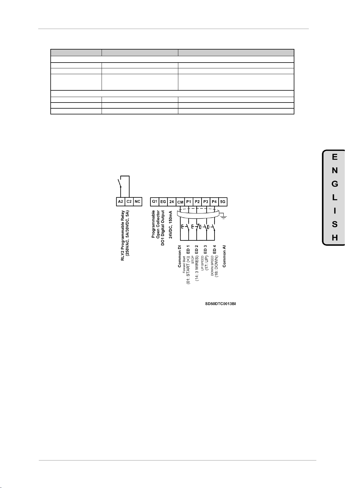
POWER ELECTRONICS
SD500
COMMONLY USED CONFIGURATIONS
77
Parameter
Name / Description
Value
G11: Protections
11 ETH1min= +150%
G11.11 / Overcurrent Level During 1 Minute
150%
12 ETHcont== 120%
G11.12 / Continuous Overcurrent Level
105%
13 ThMM= None
G11.13 / Action Selection in case of
Thermoelectronic Fault
None Protection is disabled.
FreeRun The drives output is cut which allows the motor free run
Dec Motor deceleration until stop completely.
G19: Fine Setting.
2 FREQ= 2.0kHz
G19.1.2 / Modulation Frequency
2.0kHz
2 T Boost= Manual
G19.2.2 / Initial Voltage
Manual Start Torque
5 STR FRQ= 0.50Hz
G19.2.6 / Slip Compensation
0,1Hz Minimum Start Output.
7.3.2. Connections Diagram
CM / P1 Terminals: Start key (status NO).
CM / P2 Terminals: Stop key (status NC).
CM / P3 Terminals: Up Speed key (status NO).
CM / P4 Terminals: Down Speed key (status NO).
Figure 7.3 Speed control through keypad
The 5G terminal will be the CM for drives greater or equal to 30kW.
Note: The control cables have to be screen and must be ground connected.
The start order will be executed by the use of a NO key between the CM and the P1. The stop
order will be executed by the use of a NC key between the CM and P2. When the start P1 order is
given, (regular CM), the drive will start at minimum speed established in parameter G19.2.5. If P·
button is pressed, the speed will increase according to the acceleration ramp G5.1. When stop,
the speed reference will remain if parameter G5.16 is enabled (reference saving).

SD500
POWER ELECTRONICS
78
COMMONLY USED CONFIGURATIONS
Parameter
Name / Description
Value
G1: Options Menu
3 PROG= STANDARD
3 PROG= STANDARD
3 PROG= STANDARD
G2: Nameplate.
1 Aci/pVolt= 380V
G2.1.1 / Input Voltage
In order to set the input voltage
2 I/P Freq=50Hz
G2.1.2 / Input frequency
50.00Hz – Electric supply frequency.
1 MTRPWR= 0.0kW
G2.2.1 / Motor rated Power
__kW (Set according to the motor nameplate).
2 MTR CUR= 0.0A
G2.2.2 / Motor rated current
__A (Set according to the motor nameplate).
3 NOLOADC= 0.0A
G2.2.3 / No load current
__A (Set according to the motor nameplate).
4 MTR VOLT= 0V
G2.2.4 / Motor nominal voltage
__V (Set according to the motor nameplate).
5 POLE Number= 4
G2.2.5 / Motor Poles
__ (Set according to the motor nameplate).
6 ADJTSPD= 100.0%
G2.2.6 / Fine speed setting
__(Set according to the motor nameplate).
7 EFICIENC= +85%
G2.2.7 / Motor Efficiency
__ (Set according to the motor nameplate).
8 MTR FRC = 60.00Hz
G2.2.8 / Motor frequency
__Hz (Set according to the motor nameplate).
9 MTRCOOL=SELF
G2.2.9 / Motor cooling
SELF Motor Self cooling.
FORCED Motor with forced cooling.
G3: References.
1 REF1 SP= LOCAL
G3.1 / Speed Reference Source 1
LOCAL The reference will be introduced by the use of the
keypad and set on [G3.2LOCAL]
3 LCLSP= 0.50Hz
G3.3 / Local Speed Reference
50.0Hz
G4: Inputs – S4.1: Digital I/P
1 CONTROL MODE1=1
Main Control Mode
1 REMOTE (The drive is controlled from the control terminals).
3 DI1=01
G4.1.3 / Multifunction Digital Input 1
Configuration
01 Start/Stop (In order to send commands through switch)
7 DI5=07
G4.1.7 / Multifunction Digital Input 5
Configuration
07 SPEED-L. Low bit for speed multi-references selection
8 DI6=08
G4.1.8 / Multifunction Digital Input 6
Configuration
08 SPEED-M. Medium bit for speed multi-references selection
9 DI7=09
G4.1.9 / Multifunction Digital Input 7
Configuration
09 SPEED-H. –A. High bit for speed multi-references selection
10 DI8=10
G4.1.10 / Multifunction Digital Input 8
Configuration
10 SPEED-X. Extra bit for speed multi-references selection
G7: Start / Stop Mode Configuration
2 StrDly= 0.00s
G7.2 / Start Delay Time
5.0s Start delay time.
10 Run Aft Rst= N
G7.10 / Start after Low Voltage Fault
NO Disables the start function after fault due to low supply
voltage.
YES Enables the start function after the fault caused by low
supply voltage.
11 Str Aft Rst= N
G7.11 / Start after reset due to fault
NO Disables the start function after reset.
YES Enables the start function after reset.
G10: Limits.
1 LVMax= 50.00Hz
G10.1 / Maximum Speed Limit
50Hz Equipment speed limit
3 UseFrqLimit= Y
G10.3 / Frequency Limit
YES The limits are set in parameters G10.4 and G10.5.
4FqLtLo= 0.50Hz
G10.4 / Lower Frequency Limit
25.00Hz
5 FqLtHi= 50.00Hz
G10.5 / Upper Frequency Limit
50.00Hz
G11: Protections
11 ETH1min= +150%
G11.11 / Overcurrent Level During 1 Minute
150%
12 ETHcont== 120%
G11.12 / Continuous Overcurrent Level
105%
13 ThMM= None
G11.13 / Action Selection in case of
Thermoelectronic Fault
None Protection is disabled.
FreeRun The drives output is cut which allows the motor free run
Dec Motor deceleration until stop completely.
7.4. Start / Stop Commands by Terminals and 15
Selectable Speeds by Digital Inputs.
7.4.1. Parameters Configuration

POWER ELECTRONICS
SD500
COMMONLY USED CONFIGURATIONS
79
Parameter
Name / Description
Value
G14: Multi-references.
1 MREF 1=10.0Hz
G14.1 / Multi-Reference 1
10.0Hz In order to set the speed reference 1 for the drive. (Set
according to the application needs).
2 MREF 2=20.0Hz
G14.2 / Multi-Reference 2
20.0Hz In order to set the speed reference 2 for the drive. (Set
according to the application needs).
3 MREF 3=30.0Hz
G14.3 / Multi-Reference 3
30.0Hz In order to set the speed reference 3 for the drive. (Set
according to the application needs).
4 MREF 4=40.0Hz
G14.4 / Multi-Reference 4
40.0Hz In order to set the speed reference 4 for the drive. (Set
according to the application needs).
5 MREF 5=50.0Hz
G14.5 / Multi-Reference 5
50.0Hz In order to set the speed reference 5 for the drive. (Set
according to the application needs).
6 MREF 6=50.0Hz
G14.6 / Multi-Reference 6
50.0Hz In order to set the speed reference 6 for the drive. (Set
according to the application needs).
7 MREF 7=50.0Hz
G14.7 / Multi-Reference 7
50.0Hz In order to set the speed reference 7 for the drive. (Set
according to the application needs).
8 MREF 8=50.0Hz
G14.8 / Multi-Reference 8
50Hz In order to set the speed reference 8 for the drive. (Set
according to the application needs).
9 MREF 9=50.0Hz
G14.9 / Multi-Reference 9
50.0Hz In order to set the speed reference 9 for the drive. (Set
according to the application needs).
10 MREF 10=45.0Hz
G14.10 / Multi-Reference 10
45.0Hz In order to set the speed reference 10 for the drive. (Set
according to the application needs).
11 MREF 11=40.0Hz
G14.11 / Multi-Reference 11
40.0Hz In order to set the speed reference 11 for the drive. (Set
according to the application needs).
12 MREF 12=35.0Hz
G14.12 / Multi-Reference 12
35.0Hz In order to set the speed reference 12 for the drive. (Set
according to the application needs).
13 MREF 13=25.0Hz
G14.13 / Multi-Reference 13
25.0Hz In order to set the speed reference 13 for the drive. (Set
according to the application needs).
14 MREF 14=15.0Hz
G14.14 / Multi-Reference 14
15.0Hz In order to set the speed reference 14 for the drive. (Set
according to the application needs).
15 MREF 15=5.0Hz
G14.15 / Multi-Reference 15
5.0Hz In order to set the speed reference 15 for the drive. (Set
according to the application needs).
PARM
REF
DIGITAL. O: SPEED
X H M L G14.1
MREF 1
0 0 0
X
G14.2
MREF 2
0 0 X
0
G14.3
MREF 3
0 0 X X G14.4
MREF 4
0 X 0
0
G14.5
MREF 5
0 X 0
X
G14.6
MREF 6
0 X X 0 G14.7
MREF 7
0 X X
X
G14.8
MREF 8
X 0 0
0
G14.9
MREF 9
X 0 0 X G14.10
MRF 10
X 0 X
0
G14.11
MRF 11
X 0 X
X
G14.12
MRF 12
X X 0 0 G14.13
MRF 13
X X 0
X
G14.14
MRF 14
X X X
0
G14.15
MRF 15
X X X
X
Depending on the status of the input terminals P5, P6, P7 and P8 different programmed
frequencies can be selected:

SD500
POWER ELECTRONICS
80
COMMONLY USED CONFIGURATIONS
7.4.2. Connections Diagram
CM / P1 Terminals: Start order (status NO).
CM / P5 Terminals: Multireference SPEED-L (status NO).
CM / P6 Terminals: Multireference SPEED-M (status NO).
CM / P7 Terminals: Multireference SPEED-A (status NO).
CM / P8 Terminals: Multireference SPEED-X (status NO).
Figure 7.4 Multispeeds Control through terminals P5, P6, P7, P8.
Note: The control cables have to be screen and must be ground connected.
The 5G terminal is different to the CM one for 3,7 to 22kW drives.

POWER ELECTRONICS
SD500
COMMONLY USED CONFIGURATIONS
81
Parameter
Name / Description
Value
G1: Options Menu
5 INITIALISE= NO
G1.5 / Initiate to default values.
YES All the parameters will be initialised. The user should
initialise all of the drive parameters before commissioning.
3 PROG = PUMP
G1.3 / Program activation
PUMP
G2: Nameplate.
1 Aci/pVolt= 380V
G2.1.1 / Input Voltage
In order to set the supply voltage.
2 I/P Freq= 50Hz
G2.1.2 / Input frequency
50.00Hz – Electric supply frequency.
1 MTRPWR= 0.0kW
G2.2.1 / Motor rated Power
__kW (Set according to the motor nameplate).
2 MTR CUR= 0.0A
G2.2.2 / Motor rated current
__A (Set according to the motor nameplate).
3 NOLOADC= 0.0A
G2.2.3 / No load current
__A (Set according to the motor nameplate).
4 MTR VOLT= 0V
G2.2.4 / Motor nominal voltage
__V (Set according to the motor nameplate).
5 POLE Number= 4
G2.2.5 / Motor Poles
__ (Set according to the motor nameplate).
6 ADJTSPD= 100.0%
G2.2.6 / Fine speed setting
__(Set according to the motor nameplate).
7 EFICIENC= +85%
G2.2.7 / Motor Efficiency
__ (Set according to the motor nameplate).
8 MTR FRC = 50.00Hz
G2.2.8 / Motor frequency
__Hz (Set according to the motor nameplate).
9 MTRCOOL=SELF
G2.2.9 / Motor cooling
SELF Motor Self cooling.
FORCED Motor with forced cooling.
G4: Inputs – S4.1: Digital I/P
1 CONTROL MODE1=1
G4.1.1 / Main Control Mode
1 REMOTE (The drive is controlled from the control terminals.).
3 DI1=1
G4.1.3 / Multifunction Digital Input 1
Configuration
01 START (+) (In order to command the ‘Inverse Start’ order
through the selector (NO)).
8 DI6=0
G4.1.8 / Multifunction Digital Input 6
Configuration
00 MRefPID-H. High bit to select PID multi- references
9 DI7=0
G4.1.9 Multifunction Digital Input 7
Configuration
00 MRefPID-M. Medium bit to select PID multi- references
10 DI8=0
G4.1.10 / Multifunction Digital Input 8
Configuration
00 MRefPID-L. Low bit to select PID multi- references
G7: Start / Stop Mode Configuration.
2 StrDly= 0.00s
G7.2 / Start Delay Time
5.0s Start delay.
10 Run Aft Rst= N
G7.10 / Start after Low Voltage Fault
NO Disables the start function after fault due to low supply
voltage.
YES Enables the start function after fault caused by low supply
voltage.
11 Str Aft Rst= N
G7.11 / Start after reset due to fault
NO Disables the start function after reset.
YES Enables the start function after reset.
G8: Outputs – S8.1 Digital O/P.
2 RLY1= PUMP
G8.1.2 / Relay 1 Control Source Selection
25 PUMP
3RLY1= PUMP
G8.1.3 / Relay 2 Control Source Selection
25 PUMP
4 DOP1= READY
G8.1.4 / Digital Output 1 Control Source
Selection
22 READY
G10: Limits.
1 MxSpL= 50.00Hz
G10.1 / Maximum Speed Limit
100.0% Drive limit speed.
3 UseFrqLimit= Y
G10.3 / Frequency Limit
YES The limits are set in parameters [G10.4 and G10.5].
4FqLtLo= 0.50Hz
G10.4 / Lower Frequency Limit
25.00Hz (Set depending on the pump manufacturer).
5 FqLtHi= 50.00Hz
G10.5 / Upper Frequency Limit
50.00Hz
G11: Protections.
13 ThMM= None
G11.13 / Action Selection in case of
Thermoelectronic Fault
None Protection is disabled.
FreeRun The drives output is cut which allows the motor free run
Dec Motor deceleration until stop completely.
16 ULFM= None
G11.16 / Action Selection in case of
Underload Fault
None No action will be executed.
FreeRun The drives output is cut which allows the motor free run
Dec Motor deceleration until stop completely.
7.5. Control of the Main Pump 1 and Auxiliary Pump 2,
Seven References by Screen (Underload).
7.5.1. Parameters Configuration

SD500
POWER ELECTRONICS
82
COMMONLY USED CONFIGURATIONS
Parameter
Name / Description
Value
G11: Protections.
17 ULFltDI= 30.0s
G11.17 / Delay Time Enabling Underload
Fault
60.0s
18 UlMnL = +30%
G11.18 / Underload Detection Lower Level
+30%
19 ULMxL= +30%
G11.19 / Underload Detection Upper Level
+30%
G25: Pump Control – S25.1 System Setpoint
1 MREF1= 10.00%
G25.1.1 / PID Local Reference 1
10.0Hz In order to set the speed reference 1 for the drive. (Set
according to the application needs).
2 MREF2= +20.00%
G25.1.2 / PID Local Reference 2
20.0Hz In order to set the speed reference 2 for the drive. (Set
according to the application needs).
3 MREF3= +30.00%
G25.1.3 / PID Local Reference 3
30.0Hz In order to set the speed reference 3 for the drive. (Set
according to the application needs).
4 MREF4= +40.00%
G25.1.4 / PID Local Reference 4
40.0Hz In order to set the speed reference 4 for the drive. (Set
according to the application needs).
5 MREF5= +50.00%
G25.1.5 / PID Local Reference 5
50.0Hz In order to set the speed reference 5 for the drive. (Set
according to the application needs).
6 MREF6= +50.00%
G25.1.6 / PID Local Reference 6
50.0Hz In order to set the speed reference 6 for the drive. (Set
according to the application needs).
7 MREF7= +50.00%
G25.1.7 / PID Local Reference 7
50.0Hz In order to set the speed reference 7 for the drive. (Set
according to the application needs).
G25: Pump Control – S25.2 PID
1 PIDSetp= MREF
G25.2.1 / PID Setpoint Source
MREF PID set point introduced from keypad
2 PID Fbk= AI2
G25.2.2 / PID Feedback Source
AI1Feedback voltage signal through analog input 1.
AI2Feedback current signal through analog input 2.
G25: Pump Control – S25.3 Start Conditions
1 LP Pon= 35%
G25.3.1 / Awakening Level
35%
2 FP1 Son= 49.00Hz
G25.3.2 / Fix Pump 1 Starting Speed
49.00Hz
3 FP2 Son = 49.00Hz
G25.3.3 / Fix Pump 2 Starting Speed
49.00Hz
6 FP Ton= 180.0s
G25.3.6/ Fix Pumps Starting Delay
60.0s
G25: Pump Control – S25.4 Stop Conditions
1 LP T Slpr= 20.0s
G25.4.1 / Delay Before Enabling Sleep
Mode
20.0s
2 Slp Spd= 30.0Hz
G25.4.2 / Enabling Sleep Mode Speed
30.0Hz (Set this value at least 1 Hz over the value set in [G10.4]
3 SPD1of= 43.0Hz
G25.4.3 / Fix Pump 1 Stopping Speed
43.0Hz (Set this value at least 1 Hz over the value set in [G25.4.2])
4 SPD2of = 43.0Hz
G25.4.4 / Fix Pump 2 Stopping Speed
43.0Hz
7 Fp Tof= 17.0s
G25.4.7 / Stopping Fix Pump Delay
17.0s (Set a lower value than the one set in parameter [G25.4.1])
8 FP Error= 2%
G25.4.8 / PID Maximum Error Stopping Fix
Pumps
2%
G25: Pump Control – S25.9 Enable Pump
1 First FP= 1
G25.9.1 / First Fixed Pump Selection
1
2 FP number= 0
G25.9.2 / Number of Fixed Pumps Selection
2
DIGITAL INPUTS
PID REFERENCE
DI6=00
DI7=00
DI8=00
0 0 X
G25.1.1 ‘M_Ref1’
0 X 0
G25.1.2 ‘M_Ref2’
0 X X
G25.1.3 ‘M_Ref3’
X 0 0
G25.1.4 ‘M_Ref4’
X 0 X
G25.1.5 ‘M_Ref5’
X X 0
G25.1.6 ‘M_Ref6’
X X X
G25.1.7 ‘M_Ref7’
Depend on the status of the input terminals P6, P7 and P8 we could select the different
programmed frequencies:

POWER ELECTRONICS
SD500
COMMONLY USED CONFIGURATIONS
83
7.5.2. Connections Diagram
Q1 / P1 Terminals: Start command (status NO).
EG / CM Terminals: Bridge.
CM / P6 Terminals: PID-H Bit high Multireference (status NO).
CM / P7 Terminals: PID-M Bit medium Multireference (status NO).
CM / P8 Terminals: PID-L Bit low Multireference (status NO).
IMPORTANT NOTE: In order to provide a greater safety when starting auxiliary pumps, the start
command will be disabled whenever the drive is in fault status. Therefore, it is important to
configure properly the relay outputs, the digital outputs and to carry out the connections as shown
in the diagram below:
Figure 7.4 Pump Control with several speed references through terminals P6, P7 and P8.
Note: The control cables have to be screen and must be ground connected.
The 5G terminal is different to the CM one for 3,7 to 22kW drives.

SD500
POWER ELECTRONICS
84
CONFIGURATION REGISTER
PARÁMETERS
DEFAULT SETTINGS
SETTING 1
SETTING 2
G1: OPTIONS MENU
1 LOCK PARMTRS= N
N
___________________
___________________
PASSWORD= 0
0
___________________
___________________
ERRPWD= XXXX
0000
___________________
___________________
2LOCK SCRENS= N
N
___________________
___________________
PASSWORD= 0
0
___________________
___________________
ERRPWD= XXXX
0000
___________________
___________________
3 PROG= STANDARD
STANDARD
___________________
___________________
4 LANGUA= ENGLISH
ENGLISH
___________________
___________________
5 INITIALIZE= NO
NO
___________________
___________________
8. CONFIGURATION REGISTER
SPEED DRIVE: SD500.
SERIES NUMBER: MODEL:
APPLICATION:
DATE:
CUSTOMER:
NOTES:

POWER ELECTRONICS
SD500
CONFIGURATION REGISTER
85
PARAMETERS
DEFAULT SETTINGS
SETTING 1
SETTING 2
6 UPLOAD= N
N
___________________
___________________
Upload STS=
-
___________________
___________________
7 DOWNLOADM= N
N
___________________
___________________
DownloadSts=
-
___________________
___________________
8 Changed Para= N
NO
___________________
___________________
9 ADMIN PW= 0
0
___________________
___________________
10 LCDContra= 60
60
___________________
___________________
11 FAN= Run
Run
___________________
___________________
12 ENB/DIS L/R=D
D
___________________
___________________
G2: Nameplate – S2.1: Drive Parameters
Aci/pVolt= 380V
220V220
440V380
___________________
___________________
2 I/P Freq= 50Hz
50Hz
___________________
___________________
3 TrimPwr%= +100%
_%
___________________
___________________
G2: Nameplate – S2.2: Motor Parameters
1 MTRPWR= 0.0kW
_._kW
___________________
___________________
2 MTR CUR= 0.0A
_._A
___________________
___________________
3 NOLOADC= 0.0A
_._A
___________________
___________________
4 MTR VOLT= 0V
_V
___________________
___________________
5 POLE Number= 4
__
___________________
___________________
6 ADJTSPD= 100.0%
100.0%
___________________
___________________
7 EFICIENC= +85%[
_%
___________________
___________________
8 MTR FRC = 50.00Hz
50Hz
___________________
___________________
9 MTRCOOL=SELF
Self
___________________
___________________
G3: References
1 REF1 SP= LOCAL
LOCAL
___________________
___________________
2 REF2 SP= LOCAL
LOCAL
___________________
___________________
3 LCLSP= 0.00Hz
0.00Hz
___________________
___________________
4 REF1 TQ = LOCAL
LOCAL
___________________
___________________
5 REF2 TQ =LOCAL
LOCAL
___________________
___________________
6 LclTQ = 0%
0%
___________________
___________________
G4: Inputs – S4.1: Digital I/P
1 CONTROL MODE1= 1
REMOTE
___________________
___________________
2 CONTROL MODE2= 1
REMOTE
___________________
___________________
3 DI1= START (+)
START (+)
___________________
___________________
4 DI2= START(-)
START (-)
___________________
___________________
5 DI3= DIS START
DIS START
___________________
___________________
6 DI4= EXT TRIP
EXT TRIP
___________________
___________________

SD500
POWER ELECTRONICS
86
CONFIGURATION REGISTER
PARÁMETERS
DEFAULT SETTINGS
SETTING 1
SETTING 2
7 DI5= SPEED-L
SPEED-L
___________________
___________________
8 DI6= SPEED-M
SPEED-M
___________________
___________________
9 DI7= SPEED-H
SPEED-H
___________________
___________________
10 DI8= INCH 1
INCH 1
___________________
___________________
14 DIOnF= 10ms
10ms
___________________
___________________
15 DIOffF= 3ms
3ms
___________________
___________________
16 DCTy= 00000000
00000000
___________________
___________________
17 DiScan= 1ms
1ms
___________________
___________________
18 SaveMot Frq= N
N
___________________
___________________
G4: Inputs – S4.2: Analog Input 1
1 An1PT= 0-10v
0-10v
___________________
___________________
2 Ain1LPF= 10ms
10ms
___________________
___________________
3 A1MnV= +0.00V
+0.00V
___________________
___________________
4 A1MnRf= +0.00%
+0.00%
___________________
___________________
5 A1MxV= +10.00V
+10.00V
___________________
___________________
6 A1MxR= +100.00%
+100.00%
___________________
___________________
7 An1NgMn=+0.00V
+0.00V
___________________
___________________
8 A1MnR= +0.00%[
+0.00%
___________________
___________________
9 A1MxR= -10.00V
-10.00V
___________________
___________________
10 A1MxR= -100.00
-100.00%
___________________
___________________
11 A1DeLI= 0.04
0.04%
___________________
___________________
12 MxFqA=50.00Hz
50.00Hz
___________________
___________________
G4: Inputs – S4.3: Analog Input 2
1 Ain2LPF= 10ms
10ms
___________________
___________________
2 A2MnC= 4.00mA
4.00mA
___________________
___________________
3 A2MnR= +0.00%
+0.00%
___________________
___________________
4 A2MxC= 20.00mA
20.00mA
___________________
___________________
5 A2MxR= +100.00%
+100.00%
___________________
___________________
6 A2DeLl= 0.04%
0.04%
___________________
___________________
7 MxFqA=50.00Hz
50.00Hz
___________________
___________________
G5: Acceleration and Deceleration Ramps
1 ACC1= 20.0s
20.0s
___________________
___________________
2 DECEL1= 30.0s
30.0s
___________________
___________________
4 RmpT= MaxFreq
MaxFreq
___________________
___________________
5 AccPn= Linear
Linear
___________________
___________________

POWER ELECTRONICS
SD500
CONFIGURATION REGISTER
87
PARÁMETERS
DEFAULT SETTINGS
SETTING 1
SETTING 2
6 DecPn= Linear
Linear
___________________
___________________
7 AcSSrt= +40%
+40%
___________________
___________________
8 AccSEnd= +40%
+40%
___________________
___________________
9 DeISSrt= +40%
+40%
___________________
___________________
10 DecSEnd=+40%
+40%
___________________
___________________
11 AccDWF= 5.00Hz
5.00Hz
___________________
___________________
12 AccDWT= 0.0s
0.0s
___________________
___________________
13 DecDWF= 5.00Hz
5.00Hz
___________________
___________________
14 DecDWT= 0.0s
0.0s
___________________
___________________
15 TDedFll= 3.0s
3.0s
___________________
___________________
G5: Acceleration and Deceleration Ramps – S5.16: Alternative Ramps
1 ACC2= 20.0s
20.0s
___________________
___________________
2 DEC2= 20.0s
20.0s
___________________
___________________
3 ACC3= 30.0s
30.0s
___________________
___________________
4 DEC3= 30.0s
30.0s
___________________
___________________
5 ACC4= 40.0s
40.0s
___________________
___________________
6 DEC4= 40.0s
40.0s
___________________
___________________
G6: PID Control
1 SEL REF= MREF
MREF
___________________
___________________
2 SEL FBK= AI1
AI1
___________________
___________________
3 GainKp= +50.0%
+50.0%
___________________
___________________
4 INTEGRL= 10.0s
10.0s
___________________
___________________
5 T Der= 0ms
0ms
___________________
___________________
6 MxSL= +50.00Hz
+50.00Hz
___________________
___________________
7 MnSL= 0.00Hz
0.00Hz
___________________
___________________
8 INVERT PID= N
N
___________________
___________________
9 OutSc= +100.0%
+100.0%
___________________
___________________
G7: Start / Stop Mode Configuration
1 START= RAMP
RAMP
___________________
___________________
2 StrDly= 0.00s
0.00s
___________________
___________________
3 STOP= RAMP
RAMP
___________________
___________________
4 SAFE STOP=N
N
___________________
___________________
5 SFSStr= 125.0%
125.0%
___________________
___________________
6 SFSStp = 130.0%
130.0%
___________________
___________________
7 SFSGain= 1000
1000
___________________
___________________

SD500
POWER ELECTRONICS
88
CONFIGURATION REGISTER
PARÁMETERS
DEFAULT SETTINGS
SETTING 1
SETTING 2
10 Run Aft Rst= N
N
___________________
___________________
11 Str Aft Rst= N
N
___________________
___________________
12 DCSt T= 0.00s
0.00s
___________________
___________________
13 DC Curr= 50%
50%
___________________
___________________
14 PreDC T= 0.10s
0.10s
___________________
___________________
15 DCBrk T= 1.00s
1.00s
___________________
___________________
16 DCBk Cur= 50%
50%
___________________
___________________
17 DCBk F= 5.00Hz
5.00Hz
___________________
___________________
19 PreExt = 1s
1s
___________________
___________________
20 PreExF = 100%
100%
___________________
___________________
21 PwofDI = 1s
1s
___________________
___________________
G7: Start / Stop Mode Configuration – S7.18: Speed Search
1 Srch Mode= 0000
0000
___________________
___________________
2 Srch I= 150%
150%
___________________
___________________
3 Kp Srch= 100
100
___________________
___________________
4 Ki Srch= 200
200
___________________
___________________
5 Srch Dly= 1.0s
1.0s
___________________
___________________
G8: Outputs – S8.1: Digital O/P
1 OP FLT RLY= 0X0
0X0
___________________
___________________
2 RLY1= Trip
Trip
___________________
___________________
3 RLE2= Run
Run
___________________
___________________
4 DOP1= FDT-1
FDT-1
___________________
___________________
5 T RL ON= 0.00s
0.0s
___________________
___________________
6 T RL OF= 0.00
0.0s
___________________
___________________
7 INV NA/NC= 000
000
___________________
___________________
G8: Outputs – S8.2: Analog O/P
1 A01= Frequency
Frequency
___________________
___________________
2 AO1Ga= +100.0%
100.0%
___________________
___________________
3 AO1Ofst= +0.0%
0.0%
___________________
___________________
4 AO1OFil = 5ms
5ms
___________________
___________________
5 AO1Con= 0.0%
0.0%
___________________
___________________
6 AO2= Frequency
Frequency
___________________
___________________
7 OA2Ga= +100.0%
100.0%
___________________
___________________
8 AO2Ofst= +20.0%
20.0%
___________________
___________________

POWER ELECTRONICS
SD500
CONFIGURATION REGISTER
89
PARÁMETERS
DEFAULT SETTINGS
SETTING 1
SETTING 2
9 AO2Fil= 5ms
5ms
___________________
___________________
10 AO2Con= 0.0%
0.0%
___________________
___________________
G9: Comparator
1 FDTLvl= 30.00Hz
30.00Hz
___________________
___________________
2 FDTBnd= 10.00Hz
10.00Hz
___________________
___________________
3 SLCOM= None
None
___________________
___________________
4 S C ON= +90.00%
+90.00%
___________________
___________________
5 S C OF= +10.00%
+10.00%
___________________
___________________
G10: Limits
1 MxSpL= 50.00Hz
60.00Hz
___________________
___________________
2 FWR/RV= None
None
___________________
___________________
3 UseFrqLimit=Y
S
___________________
___________________
4FqLtLo= 0.50Hz
0.50Hz
___________________
___________________
5 FqLtHi= 50.00Hz
50Hz
___________________
___________________
6 TORQUE LIMIT= N
N
___________________
___________________
7 LvTrqLt= 180%
180%
___________________
___________________
G10: Limits – S10.8: Vector Lim
1 TqLimRef = LOCAL
LOCAL
___________________
___________________
2 TLposFW = 180%
180%
___________________
___________________
3 TLnegFW = 180%
180%
___________________
___________________
4 TLposRV = 180%
180%
___________________
___________________
5 TLnegRV = 180%
180%
___________________
___________________
6 TqOffRf = LOCAL
LOCAL
___________________
___________________
7 TqOfLO = 0%
0%
___________________
___________________
8 TqOfcmp = 0%
0%
___________________
___________________
9 SpLimRf = LOCAL
LOCAL
___________________
___________________
10 SpL (+) = 50Hz
50Hz
___________________
___________________
11 SpL (-) = 50 Hz
50 Hz
___________________
___________________
12 SpL Ga = 500%
500%
___________________
___________________
G11: Protections
1 RIRLs= None
None
___________________
___________________
3 RfLsDly= 1.0s
1.0s
___________________
___________________
4 RefLRf= 0.00Hz
0.00Hz
___________________
___________________
5 OLWarnSel= NO
NO
___________________
___________________
6 OLWrnL= +150%
+150%
___________________
___________________

SD500
POWER ELECTRONICS
90
CONFIGURATION REGISTER
PARÁMETERS
DEFAULT SETTINGS
SETTING 1
SETTING 2
7 OLWrnT= 10.0s
10.0s
___________________
___________________
8 OLTS= FreeRun
FreeRun
___________________
___________________
9 OLLevel= 180%
180%
___________________
___________________
10 TFllSC= 60.0s
60.0s
___________________
___________________
11 SBC1min= +150%
+150%
___________________
___________________
12 SBCCont= 120%
120%
___________________
___________________
13 ThMM= None
None
___________________
___________________
14 EnableUL= NO
NO
___________________
___________________
15 ULWnDI= 10.0s
10.0s
___________________
___________________
16 ULFM= None
None
___________________
___________________
17 ULFltDI= 30.0s
30.0s
___________________
___________________
18 UlMnL = +30%
+30%
___________________
___________________
19 ULMxL= +30%
+30%
___________________
___________________
20 NoMD= None
None
___________________
___________________
21 NoMtrLvl= +5%
+5%
___________________
___________________
22 NoMtrDl= 3.0s
3.0s
___________________
___________________
23 OvHM= None
None
___________________
___________________
24 OvrHtSen= None
None
___________________
___________________
25 OvrHtL= +50.0%
+50.0%
___________________
___________________
26 OvrHtAr= Low
Low
___________________
___________________
27 FANTrip=Trip
Trip
___________________
___________________
28 DBWarnED= +0%
0%
___________________
___________________
29 LSS PH= NONE
NONE
___________________
___________________
30 Ripple V=40V
40V
___________________
___________________
31 GND Fault Level = 20%
20%
___________________
___________________
32 GND Fault Tout= 30 ms
30 ms
___________________
___________________
G12: Auto-reset
1 Retry NUm= 0
0
___________________
___________________
2 Retry Dly= 1.0s
1.0s
___________________
___________________
G13: Faults History
No Fault
-
___________________
___________________
FAULT 1 INFO
-
___________________
___________________
FAULT 2 INFO
-
___________________
___________________
FAULT 3 INFO
-
___________________
___________________

POWER ELECTRONICS
SD500
CONFIGURATION REGISTER
91
PARÁMETERS
DEFAULT SETTINGS
SETTING 1
SETTING 2
FAULT 4 INFO
-
___________________
___________________
FAULT 5 INFO
-
___________________
___________________
Clr FaultHist= N
N
___________________
___________________
ENB / DIS LV Flt=D
D
___________________
___________________
G14: Multi-references
1 MREF 1= 10.00Hz
10.0Hz
___________________
___________________
2 MREF 2= 20.00Hz
20.0Hz
___________________
___________________
3 MREF 3= 30.00
30.0Hz
___________________
___________________
4 MREF 4= 40.00H
40.0Hz
___________________
___________________
5 MREF 5= 50.00Hz
50.0Hz
___________________
___________________
6 MREF 6= 50.00Hz
50.0Hz
___________________
___________________
7 MREF 7= 50.00Hz
50.0Hz
___________________
___________________
8 MREF 8= 50.00Hz
50.0Hz
___________________
___________________
9 MREF 9= 50.00Hz
50.0Hz
___________________
___________________
10 MRF 10= 45.00Hz
45.0Hz
___________________
___________________
11 MRF 11= 40.00Hz
40.0Hz
___________________
___________________
12 MRF 12= 35.00Hz
35.0Hz
___________________
___________________
13 MRF 13= 25.00Hz
25.0Hz
___________________
___________________
14 MRF 14= 15.00Hz
15.0Hz
___________________
___________________
15 MRF 15= 5.00Hz
5.0Hz
___________________
___________________
G15: INCH SPEEDS
1 InchFq= 10.00Hz
10.0Hz
___________________
___________________
2 InchAcT= 20.0s
20.0s
___________________
___________________
3 InchDeT= 30.0s
30.0s
___________________
___________________
G16: Frequency Jumps
1 Jmp Freq= NO
NO
___________________
___________________
2 Sal1 B= 10.00Hz
10.0Hz
___________________
___________________
3 Sal1 A= 15.00Hz
15.0Hz
___________________
___________________
4 Sal2 B= 20.00Hz
20.0Hz
___________________
___________________
5 Sal2 A= 25.00Hz
25.0Hz
___________________
___________________
6 Sal3 B= 30.00Hz
30.0Hz
___________________
___________________
7 Sal3 A= 35.00Hz
35.0Hz
___________________
___________________
G17: DC Brake
1 RIsCurr= 50.0%
50.0%
___________________
___________________
2 RlsDly= 1.00s
1.0s
___________________
___________________
3 FwdFrq= 1.00Hz
1.0Hz
___________________
___________________

SD500
POWER ELECTRONICS
92
CONFIGURATION REGISTER
PARÁMETERS
DEFAULT SETTINGS
SETTING 1
SETTING 2
4 RevFrq= 1.00Hz
1.0Hz
___________________
___________________
5 BrEngFr= 1.00s
1.0s
___________________
___________________
6 BrEngFr= 2.00Hz
2.0Hz
___________________
___________________
G18: Encoder
1 Enc Opt Mode = None
None
___________________
___________________
2 Enc Type Sel = LineDrive
LineDrive
___________________
___________________
3 Enc Pulse Sel = (A+B)
(A+B)
___________________
___________________
4 Enc Pulse Num = 1024
1024
___________________
___________________
5 Enc Monitor = 0 Hz
0 Hz
___________________
___________________
6 Pulse Monitor = 0 kHz
0 kHz
___________________
___________________
7 Enc Filter = 3 ms
3 ms
___________________
___________________
8 Enc Pulse x1 = 0 kHz
0 kHz
___________________
___________________
9 Enc Perc y1 = 0 %
0 %
___________________
___________________
10 Enc Pulse x2 = 100 kHz
100 kHz
___________________
___________________
11 Enc Perc y2 = 100%
100%
___________________
___________________
12 Enc Wire Check = N
N
___________________
___________________
13 Enc Check Time = 1s
1s
___________________
___________________
G19: Fine Setting – S19.1: IGBT Control
1 CTRL T.= V/Hz
V/Hz
___________________
___________________
2 FREQ= 2.0kHz
_._kHz
___________________
___________________
3 V/FPn= Linear
LINEAR
___________________
___________________
4 Torque CTRL = N
N
___________________
___________________
5 Auto Tuning = NONE
NONE
___________________
___________________
G19: Fine Setting – S19.4: V/F USER Pattern
1 UsFrq1= 15.00Hz
15.00Hz
___________________
___________________
2 User V1= 25%
25%
___________________
___________________
3 UsFrq2= 30.00Hz
30.00Hz
___________________
___________________
4 User V2= 50%
50%
___________________
___________________
5 Us Frq3= 45.00Hz
45.00Hz
___________________
___________________
6 User V3= 75%
75%
___________________
___________________
7 Us Frq4= 60.00Hz
60.00Hz
___________________
___________________
8 User V4= 100%
100%
___________________
___________________
G19: Fine Setting – S19.2: Motor Load
1 InertiaRate= 0
_
___________________
___________________
2 T Boost= Manual
Manual
___________________
___________________
3 FWBoost= +20%
+20.0%
___________________
___________________
4 RVBoost= +20%
+20.0%
___________________
___________________

POWER ELECTRONICS
SD500
CONFIGURATION REGISTER
93
PARÁMETERS
DEFAULT SETTINGS
SETTING 1
SETTING 2
5 STR FRQ= 0.50Hz
0.50Hz
___________________
___________________
6 RtSlip= 45rpm
45rpm
___________________
___________________
7 FLUX MIN= NONE
None
___________________
___________________
8 FLUX LVEL= +0%
+0%
___________________
___________________
9 Load Duty= Hevy
Hevy
___________________
___________________
G19: Fine Setting – S19.3: Motor Model
1 Rs=
-
___________________
___________________
2 LSigma=
-
___________________
___________________
3 Ls=
-
___________________
___________________
4 Tr=
-
___________________
___________________
5 ASR P1 = 50%
50%
___________________
___________________
6 ASR I1 = 300ms
300ms
___________________
___________________
7 ASR P2 = 50%
50%
___________________
___________________
8 ASR I2 = 300ms
300ms
___________________
___________________
9 SwASR = 0Hz
0Hz
___________________
___________________
10 dIASR = 0.1s
0.1s
___________________
___________________
11 RASRf = 0ms
0ms
___________________
___________________
12 OurFVec = 0ms
0ms
___________________
___________________
G20: Communication Buses – S20.1: Int485 Protocol
1ComUpdate= NO
NO
___________________
___________________
2 Slave Addr= 1
1
___________________
___________________
3 Prot= ModBus
ModBus
___________________
___________________
4 BaudR= 9600 bps
9600bps
___________________
___________________
5 Mode= D8/PN/S1
D8/PN/S1
___________________
___________________
6RespDly= 5ms
5ms
___________________
___________________
7 Salvcomms= NO
NO
___________________
___________________
G25:Pump Control – S25.1: System Setpoint
1 MREF1= +10.00%
+10.00%
___________________
___________________
2 MREF2= +20.00%
+20.00%
___________________
___________________
3 MREF3= +30.00%
+30.00%
___________________
___________________
4 MREF4= +40.00%
+40.00%
___________________
___________________
5 MREF5= +50.00%
+50.00%
___________________
___________________
6 MREF6= +50.00%
+50.00%
___________________
___________________
7 MREF7= +50.00%
+50.00%
___________________
___________________

SD500
POWER ELECTRONICS
94
CONFIGURATION REGISTER
PARÁMETERS
DEFAULT SETTINGS
SETTING 1
SETTING 2
G25:Pump Control – S25.2: PID
1 PIDSetp= MREF
MREF
___________________
___________________
2 PID Fbk= AI2
AI2
___________________
___________________
3 PID Kc= +50.0%
+50.0%
___________________
___________________
4 PID It= 10.0s
10.0s
___________________
___________________
5 PID Dt= 0.0s
0.0ms
___________________
___________________
6 MxSL= +50.00Hz
+50.00Hz
___________________
___________________
7 MnSL= 0.00Hz
0.00Hz
___________________
___________________
8 InvertPID= N
N
___________________
___________________
9 Out Sc= +100.0%
+100.0%
___________________
___________________
G25:Pump Control – S25.3: Start Conditions
1 LP Pon= 35%
35%
___________________
___________________
2 FP1 Son= 49.99Hz
49.99Hz
___________________
___________________
3 FP2 Son = 49.99Hz
49.99Hz
___________________
___________________
4 FP3 Son = 49.99Hz
49.99Hz
___________________
___________________
5 FP4 Son = 49.99Hz
49.99Hz
___________________
___________________
6 FP Ton= 60.0s
60.0s
___________________
___________________
G25:Pump Control – S25.4: Stop Conditions
1 LP T Slpr= 60.0s
60.0s
___________________
___________________
2 Slp Spd= 0.00Hz
0.00Hz
___________________
___________________
3 SPD1of= 15.0H
15.0Hz
___________________
___________________
4 SPD2of = 15.0Hz
15.0Hz
___________________
___________________
5 SPD3of = 15.0Hz
15.0Hz
___________________
___________________
6 SPD4of = 15.0Hz
15.0Hz
___________________
___________________
7 Fp Tof= 60.0s
60.0s
___________________
___________________
8 FP Error= 2%
2%
___________________
___________________
G25:Pump Control – S25.5: Speed Bypass
1 AccTime= 2.0s
2.0s
___________________
___________________
2 Dec Timel= 2.0s
2.0s
___________________
___________________
G25:Pump Control – S25.7: Filling Pipes
1 Fill Sp= 0.00Hz
0.00Hz
___________________
___________________
2 Fill P= 0.0%
0.0%
___________________
___________________
3 Fill Tim= 600s
600s
___________________
___________________
G25:Pump Control – S25.9: Enable Pump
1 First FP= 1
1
___________________
___________________
2 FP number= 0
0
___________________
___________________

POWER ELECTRONICS
SD500
95

HEADQUARTER • VALENCIA • SPAIN
C/ Leonardo da Vinci, 24 – 26 • Parque Tecnológico • 46980 – PATERNA • VALENCIA • ESPAÑA
Tel. 902 40 20 70 • Tel. (+34) 96 136 65 57 • Fax (+34) 96 131 82 01
BRANCHES
CATALONIA
BARCELONA • Avda. de la Ferrería, 86-88 • 08110 • MONTCADA I REIXAC
Tel. (+34) 96 136 65 57 • Fax (+34) 93 564 47 52
LLEIDA • C/ Terrasa, 13 · Bajo • 25005 • LLEIDA
Tel. (+34) 97 372 59 52 • Fax (+34) 97 372 59 52
CANARY
ISLANDS
LAS PALMAS • C/ Juan de la Cierva, 4 • 35200 • TELDE
Tel. (+34) 928 68 26 47 • Fax (+34) 928 68 26 47
LEVANT
VALENCIA • Leonardo da Vinci, 24-26 • Parque tecnológico ● 46980 ● PATERNA
Tel. (+34) 96 136 65 57 • Fax (+34) 96 131 82 01
CASTELLÓN • C/ Juan Bautista Poeta • 2º Piso · Puerta 4 • 12006 • CASTELLÓN
Tel. (+34) 96 136 65 57
MURCIA • Pol. Residencial Santa Ana • Avda. Venecia, 17 • 30319 • CARTAGENA
Tel. (+34) 96 853 51 94 • Fax (+34) 96 812 66 23
NORTH
VIZCAYA • Parque de Actividades • Empresariales Asuarán • Edificio Asúa, 1º B • Ctra. Bilbao · Plencia • 48950 •
ERANDIO • Tel. (+34) 96 136 65 57 • Fax (+34) 94 431 79 08
CENTRE
MADRID • Avda. Rey Juan Carlos I, 98, 4º C • 28916 • LEGANÉS
Tel. (+34) 96 136 65 57 • Fax (+34) 91 687 53 84
SOUTH
SEVILLA • C/Arquitectura, Bloque 6 • Planta 5ª • Módulo 2 • Parque Empresarial Nuevo Torneo • 41015 • SEVILLA
Tel. (+34) 95 451 57 73 • Fax (+34) 95 451 57 73
INTERNATIONAL SUBSIDIARIES
GERMANY
Power Electronics Deutschland GmbH • Dieselstrasse, 77 • D·90441 • NÜRNBERG ● GERMANY
Tel. (+49) 911 99 43 99 0 • Fax (+49) 911 99 43 99 8
AUSTRALIA
Power Electronics Australia Pty Ltd • U6, 30-34 Octal St, Yatala, • BRISBANE, QUEENSLAND 4207 • P.O. Box
6022, Yatala DC, Yatala Qld 4207 • AUSTRALIA
Tel. (+61) 7 3386 1993 • Fax (+61) 7 3386 1993
BRAZIL
Power Electronics Brazil Ltda • Av. Imperatriz Leopoldina, 263 – conjunto 25 • CEP 09770-271 • SÃO BERNARDO
DO CAMPO - SP • BRASIL • Tel. (+55) 11 5891 9612 • Tel. (+55) 11 5891 9762
CHILE
Power Electronics Chile Ltda • Los Productores # 4439 – Huechuraba • SANTIAGO • CHILE
Tel. (+56) (2) 244 0308 · 0327 · 0335 • Fax (+56) (2) 244 0395
Oficina Petronila # 246, Casa 19 • ANTOFAGASTA • CHILE
Tel. (+56) (55) 793 965
CHINA
Power Electronics Beijing • Room 606, Yiheng Building • No 28 East Road, Beisanhuan • 100013, Chaoyang
District • BEIJING • R.P. CHINA
Tel. (+86 10) 6437 9197 • Fax (+86 10) 6437 9181
Power Electronics Asia Ltd • 20/F Winbase Centre • 208 Queen’s Road Central • HONG KONG • R.P. CHINA
KOREA
Power Electronics Asia HQ Co • Room #305, SK Hub Primo Building • 953-1, Dokok-dong, Gangnam-gu • 135-270
• SEOUL • KOREA
Tel. (+82) 2 3462 4656 • Fax (+82) 2 3462 4657
INDIA
Power Electronics India • No 25/4, Palaami Center, • New Natham Road (Near Ramakrishna Mutt),• 625014 •
MADURAI
Tel. (+91) 452 452 2125• Fax (+91) 452 452 2125
ITALY
Power Electronics Italia Srl • Piazzale Cadorna, 6 • 20123 • MILANO • ITALIA
Tel. (+39) 347 39 74 792
JAPAN
Power Electronics Japan KK • Nishi-Shinbashi 2-17-2 • HF Toranomon Bldg. 5F • 105-0003 • Minato-Ku • Tokyo
Tel. (+81) 03 6355 8911 • Fax (+81) 03 3436 5465 • Email: salesjapan@power-electronics.com
MEXICO
P.E. Internacional Mexico S de RL • Calle Cerrada de José Vasconcelos, No 9 • Colonia Tlalnepantla Centro •
Tlalnepantla de Baz • CP 54000 • ESTADO DE MEXICO
Tel. (+52) 55 5390 8818 • Tel. (+52) 55 5390 8363 • Tel. (+52) 55 5390 8195
MOROCCO
Power Electronics – Ekoakua • Geea sarl , N°184 Bloc Hay EL.Massira Aït Melloul • 80150 •Agadir • Maroc
Tel: +212 5 28 30 88 33 • Mob: (+34) 628 11 76 72 • Email: ventesmaroc@power-electronics.com
NEW
ZEALAND
Power Electronics New Zealand Ltd • 12A Opawa Road, Waltham • CHRISTCHURCH 8023 • P.O. Box 1269
CHRISTCHURCH 8140
Tel. (+64 3) 379 98 26 • Fax.(+64 3) 379 98 27
UNITED
KINGDOM
Power Electronics Corp UK Ltd • Well House • 80 Upper Street • Islington • LONDON N1 ONU • UNITED
KINGDOM
Tel. 00441494370029 • Fax. (+34) 961 318 201 • Email: uksales@power-electronics.com
UNITED
STATES OF
AMERICA
Power Electronics USA Inc. • 4777 N 44th Ave • Phoenix• AZ 85031 • UNITED STATES OF AMERICA
Tel: (480) 519-5977 • Fax: (415) 874-3001 • Email: sales@power-electronics.com
www.powerelectronics.es | www.power-electronics.com
24 Hours Technical Assistance 365 days a year +34 96 136 65 57

www.power-electronics.com
 Loading...