

PowerBridge LP3D User Manual
THIS PRODUCT IS NOT TO BE INSTALLED, DIRECT WIRED, OR BRANCHED TO THE BUILDING ELECTRICAL CIRCUIT/WIRING SYSTEM !
DO NOT MODIFY OR ALTER ANY PORTION OF THE COMPONENTS OF THE FACTORY ASSEMBLED APPLIANCE
Do not install this product near water, example, near a sink, tub, shower, swimming pool or laundry area.
Manufacturer is not liable for damages due to improper installation methods not followed herein.
This product does not have built-in electronic circuitry for surge protection or A/C filtering.
It is recommended that this product be connected to a quality surge-protector/power conditioner for equipment protection.
Disclaimer. HD-Products, LLC, the Manufacturer, it's agents, suppliers, and affiliates, shall not be liable for any damages, not limited to; misuse, acts of nature,
verbal and written expression and improper installation. Improper installation is determined such to include, not limited to, non-code compliant installation, product
modifications, alterations, adjustments, and substitutions of components or materials.
Limited 2-year Warranty from Manufactures Defects: The LP3D has a Limited Two Year product warranty against manufacturer's defects.
If you have any questions or experience any problems with this product, please contact HD-Products Customer Service.
Ultra Low Profile In-Wall System
LP3LP3
POWERPOWER
DD
CABLECABLE
Low Profile Recessed In-Wall Kit Model #LP3D
Power Extension Cable Management
Kit Includes:
1- Dual Recessed PowerOUT Panel
1- PowerIN Wall Plate with in-wall wiring box
PowerOUT Panel
72” In-Wall PowerWire (ROMEX )
PowerIN Wall Panel
72” PowerConnect Cord.
Tools for Installation
Not Included
Stud Finder
Level
Drywall Saw
Flat-Blade
!
HD-Products, LLC., intent to make this manual accurate and complete. However, HD- Products, LLC., makes no claim that the information contained herein covers all details, conditions, or
variations. Nor does it provide for every possible contingency in connection with the installation or use of this product. The information contained in this document is subject to change
without notice or obligation of any kind. HD-Products, LLC., makes no representation of warranty, expressed or implied, regarding the information contained herein.
HD-Products, LLC. PowerBridge Solution 3869 Norwood Dr. Littleton, CO 80125 USA
Customer Service: Toll Free- 855.755.9838 info@powerbridgesolution.com www.PowerBridgeSolution.com
Part No. 44-12P 2012 All Rights Reserved Patent Pending
3183743
CAN/CSA STD C22.2 NO.42.1
ETL LISTED
CONFORMS TO
UL STD 514C
CERTIFIED TO
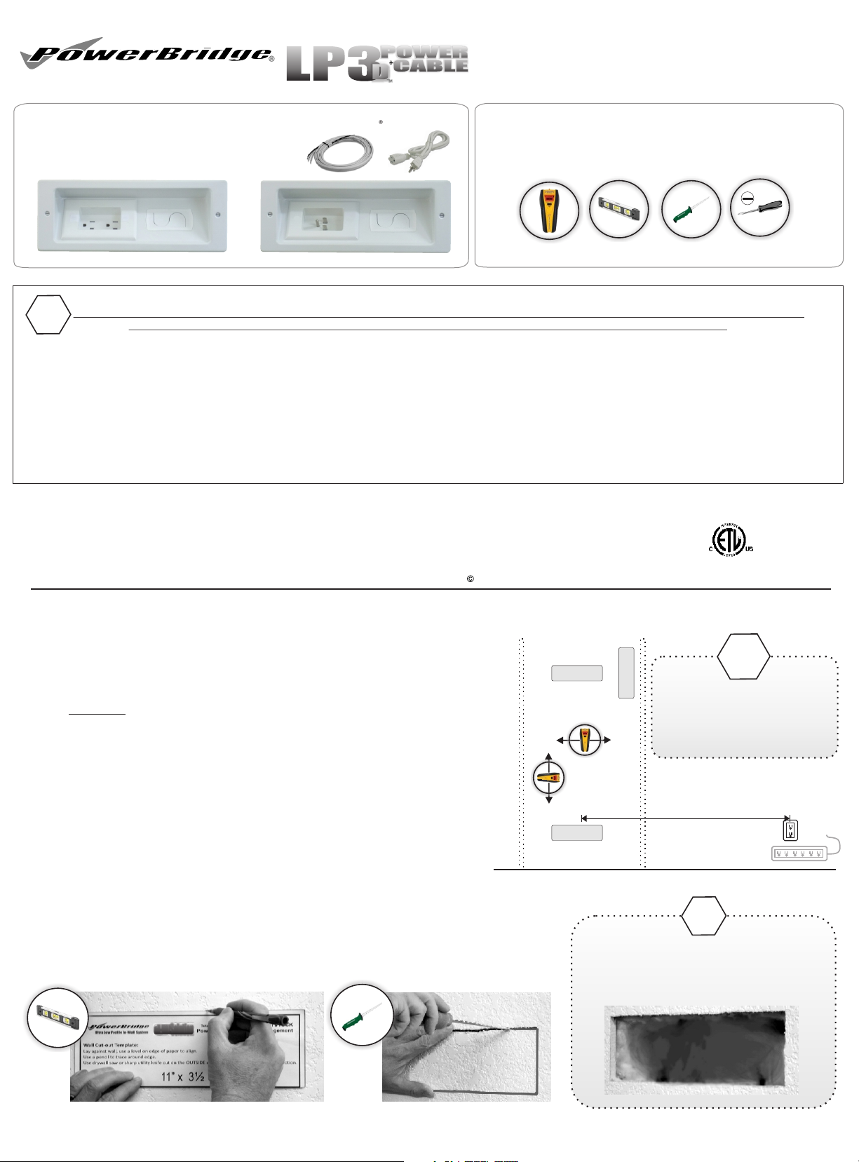
Step 1 Location - Wall Cutout
PowerOUT
PowerOUT - Determine TV wall mount bracket location.
Align between wall framing studs.
Horizontal
or Vertical
Use stud finder to determine in-wall obstructions between
framing both VERTICALLY and HORIZONTALLY.
Install in any direction, right/left, horizontal or vertical below,
above, next to TV wall bracket.
PowerIN - Usually located behind or near AV equipment.
Longer in-wall PowerWire can be installed to located up to 75’ from TV
PowerIN
Install within 60” from an existing power outlet or power-surge device.
Use supplied template sheet to mark area to cut out from drywall.
Use a level to maintain proper alignment.
Carefully use drywall saw to cut along outside of line.
LEVEL
thIN-WALL
Solution
If insulation exists, remove or push
completely away from the openings
to allow flush mounting properly.
PowerBridge can only be installed
within standard construction walls.
Only attempt installation within
2x4 or 2x6 wood/metal stud
framed wall.
Do not exceed more
than 60” apart from
existing outlet or
surge-protection unit
!
!
|
LP3D_v1413
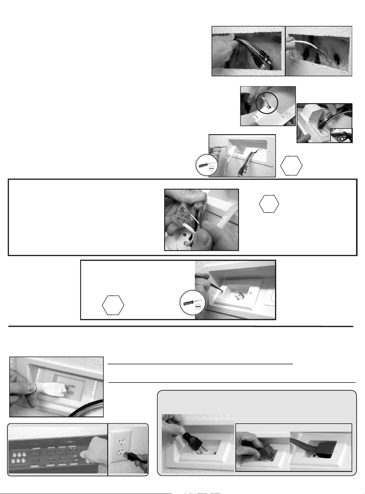
Step 2
A) Begin at the upper PowerOUT location where TV will be
mounted. Drop or wall-fish audio video cables and in-wall
PowerWire extension to the PowerIN cutout location.
B) Push in-wall PowerWire extension through the slot closest to the
middle of the attached wiring box. Push through approximately 6”
C) Slide audio video cables through backside of CableGate.
Optional: Cable zip-tie straps can be used to secure cables through CableHoops.
D) Slide BOTH OUT and IN panels into wall openings.
Use Flat-Blade screw driver to secure panel to wall.
E) Dual Outlet / Inlet Wire Connection
Insert BARE wire into the yellow wire
port with GREEN wire.
Insert WHITE wire into the yellow wire
port with WHITE wire.
Insert BLACK wire into the yellow wire
port with BLACK wire.
PowerPanel Installation
Caution.
Do not over tighten
!
!
Insert wires
completely into
the wire-ports to
lock wires securely.
Step 3
Surge Protector
Secure the Power-Plates
to PowerPanels with
supplied slotted screws.
Power UP
Caution.
Do not over tighten
!
Plug supplied 6’ PowerConnect cord into PowerIN.
Plug other end into existing grounded outlet or surge protector.
Do not use another extension cord to extend the supplied cord.
The PowerBridge In-Wall Extension is now energized.
Plug TV power supply cord in to PowerOUT and connect AV cables to TV.
Follow wall mount manufacture instructions, install TV on wall bracket.
Plug in TV
Existing
Outlet
Plug in Flat Angle Plug in the far right receptacle
 Loading...