

Page 1
SUB-W oofer
J
AD
Contr ol
ILL
INSTRUCTION MANUAL
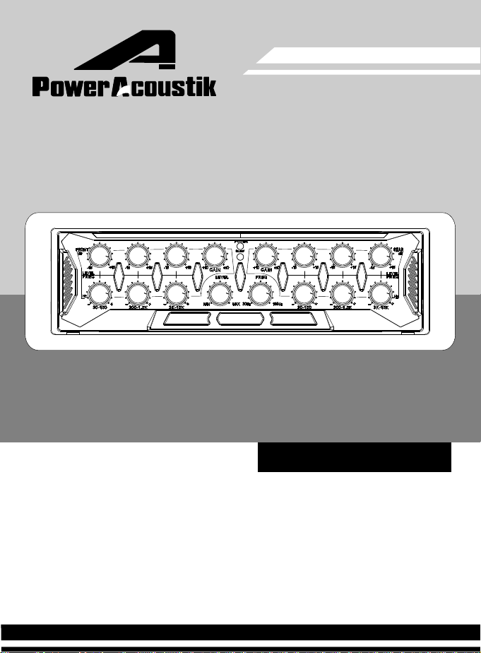
PWM-30M
6 BAND PARAMETRIC EQUALIZER
Page 2
PWM-30M
Content
INTRODUCTION
INSTALLATION
electronic connections
location of the buttons
OPERATIONS
TROUBLESHOOTING
IMPORTANT INFORMATION
Thank you for purchasing the PWM-30M6 band parametric equalizer. Please read all
instructions carefully before operation, to ensure your complete understanding and to obtain
the best possible performance from the unit.
BEFORE USE
For safety
*
Do not raise the volume level too much, as this will block outside sounds, making
driving dangerous.
Stop the car before performing any complicated operations.
To prevent short circuits, never put or insert any metallic (e.g., Coins or metal tools)
objects inside the unit.
Temperature inside the car...
*
If you have parked the car for a long time in hot or cold weather, wait until the
temperature in the car becomes normal before operating the unit.
1
2
3
5
6
9
For customer Use:
Enter below the Model Number and Serial Number which are located on the top or bottom
of the cabinet. Retain this information for future reference.
Model Number: Serial Number:
Page 3
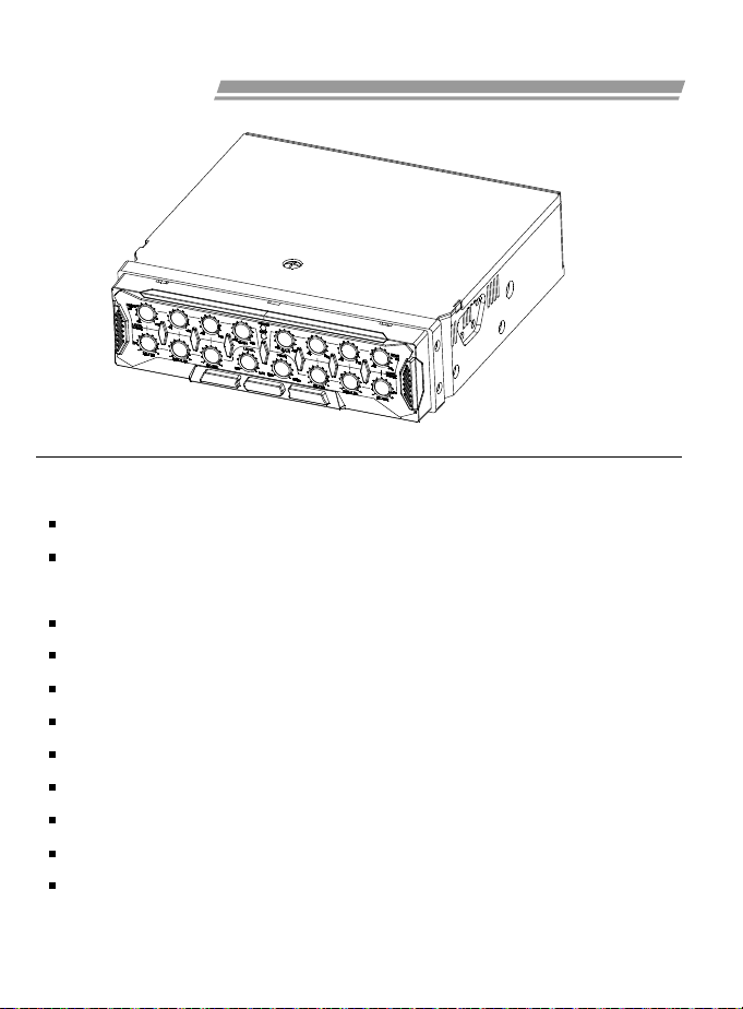
INTRODUCTION
FEATURES:
6 BAND PARAMETRIC EQUALIZER WITH 4 CHANNEL OUTPUT
IN-DASH DIN SIZE: EASY COMPOUND WITH OTHER HEAD-UNIT TO A 2-DIN
SIZE SYSTEM
MOTORIZED HIDDEN ADJUST BUTTONS
X-BREATH DUAL-COLOR INTELLECTIVE ILLUMINATION
FRONT/REAR SEPARATE EQUALIZER ADJUSTMENT
FRONT/REAR SEPARATE GAIN ADJUSTMENT
SUB-WOOFER PRE-OUT & CONTROLLER (FREQ. & GAIN)
AUTOMATIC POWER SWITCH
GOLD PLATED INPUT / OUTPUT SOCKETS
BALANCED HIGH / LOW LEVEL INPUT
NIGHT ILLUMINATION
-1-
Page 4
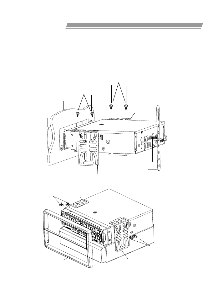
INSTALLATION
The following illustration shows a typical installation. However, you should
make adjustments corresponding to your specific car. If you have any
questions or require information regarding installation kits, consult your car
audio dealer or a company supplying kits.
In-dash single mounting
1
Screws(M5x10mm)
Frame
Screws(M5x10mm)
Bracket
Mounting bolt
Stay
Bracket
Bracket
Bracket
Dashboard
Frame
Compound with other head-unit to a 2-din size system
2
Screws(M5x6mm)
Lock nut
(M5)
Screws(M5x6mm)
-2-
Page 5
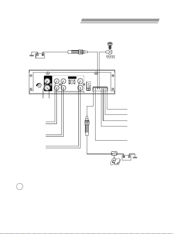
ELECTRONIC CONNECTIONS
Typical Connections
1
To the positive terminal of the car battery
(bypassing the ignition switch)
3A fuse
Yellow
To metallic body or
chassis of the car
Black
INPUT
LEVEL
0.7V7V
Left
Line in
RCA
Low le vel Input
Line out
(Front)
Line out
(Rear)
Sub-
Woofer
out
LINE IN
Right
Left
Right
Left
Right
Left
Right
FRONT
REAR
L
R
OUTPUT
L
R
SUB
GROUND ISOLATION
ISOLATED
220
Ω
GROUND
3A fuse
High Level Input
Yellow
Yellow/Black
Orange
Orange/Black
Violet
Red
To the car ignition switch
controlled power wire
(Accessory terminal)
Connection to your CD/Cassette player
2
Connect this unit's Remote On lead to your head player's remote lead if any
1
(such as auto antenna lead), so this unit's power can be controlled through
the head player. If there is no suitable lead from your audio source
equipment, connect to the car ignition switch controlled power wire
(Accessory terminal).
Note: For some models of head players, the auto antenna lead only works in
radio receiving mode.
Left +
Left Right +
Right -
Remote On
-3-
Page 6

ELECTRONIC CONNECTIONS
If your head player provides
2
RCA type line out, connect
them to this unit's Line In
socket.
Line in
Line out
Note: Do not use this unit's low level and high level input together.
Adjust the INPUT LEVEL to meet your source unit's
3
output level. Turn clockwise when your head player has a
EQ
CD/Casset te
player
speake rs
if any
If your head player does not provide RCA
type line out, then disconnect the head
player's speaker leads, connect them to
this unit's High Level Input leads.
Line in
High Level Input
CD/Casset te
player
normal level output; turn counter-clockwise if your head
player has high level preamp output.
Occasionally alternator noise may appear because the
4
source unit and amplifier may use different grounding. To
help in this situation, you may select the GROUND
ISOLATION switch to a proper position.
Connection to Subwoofer and externa l amplifier
3
Amplifier
Line in
EQ
Front spe akers
Rear spe ake rs
Subwoofer
Amplifier
Line in
Note: No low-pass filter is required for the subwoofer amplifier.
-4- -5-
Page 7

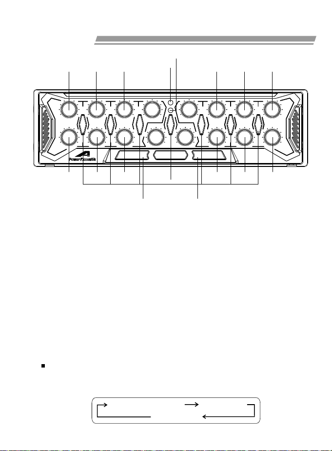
LOCATION OF THE BUTTONS
4
F1-L F2-L F3-L F4 R4 R1-L R2-L R3-L
3
FRONT
+15-15
dB
LEVEL
Hz
Low
FRE Q
F1-F
Front Band 1 Level Adjust Button
F1-L
Front Band 2 Level Adjust Button
F2-L
Front Band 3 Level Adjust Button
F3-L
Front Band 1 Frequence Adjust Button
F1-F
Front Band 2 Frequence Adjust Button
F2-F
Front Band 3 Frequence Adjust Button
F3-F
F4
Front Gain Adjust Button
R1-L
Rear Band 1 Level Adjust Button
R2-L
Rear Band 2 Level Adjust Button
R3-L
Rear Band 3 Level Adjust Button
R1-F
Rear Band 1 Frequence Adjust Button
R2-F
Rear Band 2 Frequence Adjust Button
R3-F
Rear Band 3 Frequence Adjust Button
R4
Rear Gain Adjust Button
300- 1.5K 3K-1 5K30-1 50
Low
Hi
F2-F
+15-15
+15-15
Low
Hi
F3-F R1-F R2-F R3-FS2 S3S1
Hi
ADJADJ
POWER ON
MaxMin
GAIN
LEVEL
MAXMIN
SUB- Woof er
Cont rol
1 25
SLEEP
MaxMin +15-15 +15-15 +15-15
GAIN
FREQ
30Hz
Low
180
ILLILL
300- 1.5K 3K-1 5K30-1 50
Low
Hi
SUB-Woofer Control
S-1
Low
Hi
PWM-30M
Parametric Equalizer
Button
Subwoofer Level Adjust
S-2
Button
Subwoofer Frequence
S-3
Adjust Button
1
Adjust Buttons Position
Switch
2
Illumination Switch
3
Power Indicator
4
Sleep Indicator
5
Subwoofer On/Off
Switch
LEVEL
FRE Q
REAR
dB
Hz
Hi
Page 8
Operations
4
F1-L F2-L F3-L R1-L R2-L R3-L
3
FRONT
dB
LEVEL
Hz
FRE Q
Low
F1-F
+15-15
300- 1.5K 3K-1 5K30-1 50
Low
Hi
F2-F
+15-15
+15-15
Low
Hi
F3-F R1-F R2-F R3-F
POWER ON
SLEEP
MaxMin
GAIN
LEVEL
Hi
MAXMIN
SUB- Woof er
ADJADJ
Cont rol
MaxMin +15-15 +15-15 +15-15
GAIN
FREQ
30Hz
Low
180
ILLILL
300- 1.5K 3K-1 5K30-1 50
Low
Hi
PWM-30M
Parametric Equalizer
Hi
REAR
dB
LEVEL
Hz
Low
Hi
FRE Q
1 2
Turn On/Off the unit
1
When you connect the Remote On lead, the unit will be turned
automatically on/off following the audio source equipment.
Adjust Buttons Position Switch
2
Press the 1 (Adjust Buttons Position Switch) button, the Adjust buttons
move forward for further adjustment. Press the 1 (Adjust Buttons Position
Switch) button again, the Adjust buttons move back to the normal position
to prevent accidental adjustment.
When the unit turned off, the Adjust buttons move back to the normal
position automatically.
Illumination Switch
3
The unit is in Power On Status:
Press the 2 (Illumination Switch) button, the illumination modes change
as follows:
X-Breath mode(Dual color) Red color mode
Blue color mode
-6- -7-
Page 9

Operations
The unit is in Power Off Status:
Press the 2 (Illumination Switch) button, you can turn off the X-breath
illumination.
Power Indicator
4
When the unit turned on, the 3 (power indicator) indicator lights up.
Front Equalizer Level & Frequence Adjustment
5
Adjust F1-L, F2-L, F3-L buttons to change the equalizer level of each
band.
Adjust F1-F, F2-F, F3-F buttons to change the equalizer center
frequence of each band.
g
(dB)
15
12
9
6
3
0
-3
-6
-9
-12
-15
LEVEL ADJUST CURVE CENTER FREQUENCE ADJUSTCURVE
(Hz)
f
0
g
(dB)
f1 f2
(Hz)
f
Rear Equalizer Level & Frequence Adjustment
6
Adjust R1-L, R2-L, R3-L buttons to change the equalizer level of each
band.
Adjust R1-F, R2-F, R3-F buttons to change the equalizer center
frequence of each band.
Page 10

Operations
F4 R4
FRONT
dB
LEVEL
Hz
FRE Q
+15-15
+15-15
300- 1.5K 3K-1 5K30-1 50
Low
Low
Hi
+15-15
Low
Hi
POWER ON
SLEEP
MaxMin
GAIN
LEVEL
Hi
MAXMIN
SUB- Woof er
ADJADJ
Cont rol
MaxMin +15-15 +15-15 +15-15
GAIN
FREQ
30Hz
Low
180
ILLILL
300- 1.5K 3K-1 5K30-1 50
Low
Hi
PWM-30M
Parametric Equalizer
Hi
REAR
dB
LEVEL
Hz
Low
Hi
FRE Q
S2 S3S1
(Front Channel) Gain Control
7
Adjusting F4 (Front Gain Adjust) button can change the front channel
amplifier gain level to fit your system input and output level demand.
(Rear Channel) Gain Control
8
Adjusting R4 (Rear Gain Adjust) button can change the rear channel
amplifier gain level to fit your system input and output level demand.
SUB-woofer Control
9
Press the S1 (SUB-woofer Control) button to turn on /off the SUBwoofer output.
Adjust the S2 (SUB-woofer Level) button to change the SUB-woofer
gain level
Adjust the S2 (SUB-woofer Level) button to change the SUB-woofer
cut-off frequence.
-8-
Page 11

TROUBLESHOOTING
What appears to be trouble is not always serious. Check the following
points before calling a service center.
Indication
LED
Illumination
Slowly Blue
Glow
Causes
No power
supplied
Sleep
mode
Incorrect
gain
Check the fuse and
wiring to the battery.
Check the connection
and the +12volts
power of REM.On.
Check your fro nt &
re ar gain sett ings.
setting
Remedies
Symptoms
The unit dose
not works at
all.
No sound
from the
speaker
Power Sleep
LED
Off Off Off
Off On
On Off Off
On Off Off
No input
Check your sourc es
volume, input cord .
-9-
Page 12

SPECIFICATIONS
AUDIO SECTION
S/N Ratio (Rated Power, 1KHz)
Distortion
Separation (Rated Power, 1KHz)
FREQ. Response (1KHz=0dB, +/-2dB)
RCA Input Level
RCA Input Impedance
HI-Level Input Level
HI-Level Input Impedance
Gain
Line Out Level (RMS.)
Line Out Impedance
SUB-WOOFER Output Level
SUB-WOOFER Output Cut-off FREQ.
EQ Control Range
GENERAL SECTION
Power Source
Ground System
MAX Current
Weight
Dimensions (W x H x D)
Design and specifications subject to change without notice.
100dB
0.01%
100dB
10Hz-35KHz
0.7-7V
20K
5V
100
20dB
7V
1K
6V
30Hz - 180Hz
+/- 15dB
9V-15V
NEGATIVE GROUND
1A
1.25Kg
178x50x180mm
Ω
Ω
Ω
 Loading...