

Page 1
Owner's manual
Page 2
Amplifier provide high-performance sound reinforcement for you mobile audio equipment.
It's versatility enables compatibility with optional Equalizers. Frequency Dividing Network
Crossovers, and other audio processors in a customized system. The Multi-Mode bridging
capabilities allow flexibility in hosting several different speaker configurations.
To achieve optimum performance, it is highly recommended that you read this Owners
@
Manual defore beginning installation.
THERMAL / SHORT / OVER LOAD PROTECTION
PEARL SILVER FINISH
2 OHM STEREO / 4 OHM MONO
P.W.M MOSFET POWER SUPPLY
POWER & DISTRESS INDICATOR
SELECTABLE X-OVER HPF / FULL / LPF
18
dB. BASS BOOST WITH SWITCH SUB (45Hz)
VARIABLE HI-PASS AND LOW PASS (40Hz-250Hz)
GOLD PLATED TERMINAL STRIPS / RCA JACKS
HEAW DUTY HEAT SINK
'
ADJUSTABLE INPUT SENSlTiVlTY
SOFT DELAYED REMOTE TURN-ON
LOW LEVEL INPUTS
PHANTOM CHANNEL FOR POWERING CENTER SPEAKER OR SUBWOOFER
WARNING
High powered audio systems in a vehicle are capable of generating "Live Concert" high
levels of sound pressure, Continued exposure to excessively high volume sound levels may
cause hearing loss or damage. Also, operation of a moter vehicle while listening to audio
equipment at high volume levels may impair your ability to hear external sounds such as:
horns, warning signals, or emergency vehicles, thus constituting to a potential traffic hazard.
In the interest of safety, Consumer Electronics recommends listening at lower vilume levels
while driving.
Page 3
Before beginning the installation, consider the following:
a. If you plan to expand your system by adding other components somrtime in the future,
ensure adequate space is left, and cooling requirements are met.
b. Should you use high or low inputs?
Your Amplifier ha been designed to accept either High-Level (speaker outputs from your
radio) or Low-Level (Pre-Amp outputs from your radio) signal source.
If your radiolsource is equipped with Pre-Amp outputs, it is possible to utilize them to drive
the Amplifier and connecting (Amplifier) to the 2 rear speakers. Then, use the built-in
power of your radio to drive the
2
front speakers.
NOTE:
DISTORTION LEVEL IS CONSIDERABLY LOWER FROM PRE-AMP (LOW LEVEL) OUTPUTS, THAN SPEAKER
(HIGH LEVEL) OUTPUTS.
C. Are your components matched? The peak power rating of your speakers must be equal
or greater than the Amplifier's. They also must be 2-8 Ohms limpedance (This information
os normally printed on the speaker magnet).
d. Consider both the length of your leads, and routing when determining the mounting
location. Pre-Amp input Jacks requir a length of high quality shielded male to male RCA
patch cord.
.
;
The mounting position of your Amplifier will have a great effect on its ability to dissipate the
heat generated during normal operation. It has ample heat sink for heat dissipation, and
also designed with a thermal shut-down (for heat protection) circuit, making air to be
directed over the cooling fins will improve heat dissipation dramatically. DO NOT enclose
the
amwlifier in a small box of cover it so that air cannot flow around fins.
Temperatures in car trunks have been measured as high as 175'F(80'c) in the summer time.
since the thermal shut-down point for the Amplifier is
185'F(85'c) it is easy to see that it must
be mounted for maximum cooling
capability. To achieve maximum advantage of
convection ais flow in an enclosed trunk, mount the amplifier in a vertical position, on a
vertical surface.
Cooling requirements are considerably relaxed when mounting inside the passenger
compartment since the driver will not often allow temperatures to reach a critical point.
Floor mounting under the seat is usually satisfactory as long as there is at least
1
inch(2cm)
above the Amplifier's fins for ventilation.
0
a Select a suitable location that is convenient for mounting, is accessible for wiring, and
has ample room for air circulation and cooling.
b. Use the amplifier as a template to mark the mounting holes. Remove the Amplifier and
drill 4 holes. use extreme caution, inspect underneath surface before drilling.
c. Secure the Amplifier using the screws provided.
Page 4
A. CONNECTING THE POWER (Fig. 1)
CAUTION:
AS A PRECAUTION, IT
IS
ADVISABLE TO DISCONNECTTHE VEHICLE'S BAnERY BEFORE MAKING CONNECTION
TO THE +12 VOLTS SUPPLY WIRING.
418
GAUGE(Thicker if planning for additional Amplifiers) wire is recommended both the
power and ground wires. 12 Gauge, for the remote ture-on wire. Both types are
available
at
most Mobile Audio Dealers or Installation Sho~s.
(1) GROUND: To Vehicle Chassis
To avoid unwanted ignition noise caused by ground loops, it is essential that the
Amplifier be grounded to a clean, bare, metal surface of the vehicles chassis.
NOTE:
GROUND
WIRE SHOULD NOT BE EXTENDED MORE THAN
3
FI.(1
METER).
(2) +12Volt(Fused) Constant Power: To Battery
(+)
Due to the power requirements of the Amplifier, this connection should be made
directly to the positive
(+)
terminal of battery. For safety measure, install an in-line Fuse
Holder (not included) as close to the battery positive
(+)
terminal as possible with an
ampere rating; not to exceed total value of fuses in Amp.
(3) Remote Turn-One Input : To Power Antenna output of Car Stereo
This Amplifier is turned "0N"remotely when the vehicle's stereo is turned "ON".
NOTE:
IF YOUR RADIO DOES NOT HAVE +12 VOLT OUTPUT LEAD WHEN THE RADIO IS TURNED ON.
THE
'REMn TERMINAL ON THE AMPLIFIER CAN BE CONNECTED TO VEHICLE'S ACCESSORY CIRCUIT THAT IS LIVE
WHEN THE KEY
IS
'ON'.
Page 5
B.
VARIABLE LOW-PASS FILTER (40Hz-250Hz)
For use as a dedicated subwoofer channel, set filter switch to "LPF". Adjust variable
crossover frequency with control as desired The amplifier input circuit filters out
everything above 40
.....
250Hz (dependent on the adjustment of the frequency control).
so only the deepest bass notes are amplified.
fl
C. VARIABLE HIGH-PASS FILTER (40Hz-250Hz)
For use as a dedicated mid high rangd channel, set filter switch to "HPF". The inpul
circuit filters out all frequencies below 40Hz
....
250Hz.
D.
BASS BOOS1
By using the bass boost functionthe deepest bass notes at 45Hz are emphasized.
E.
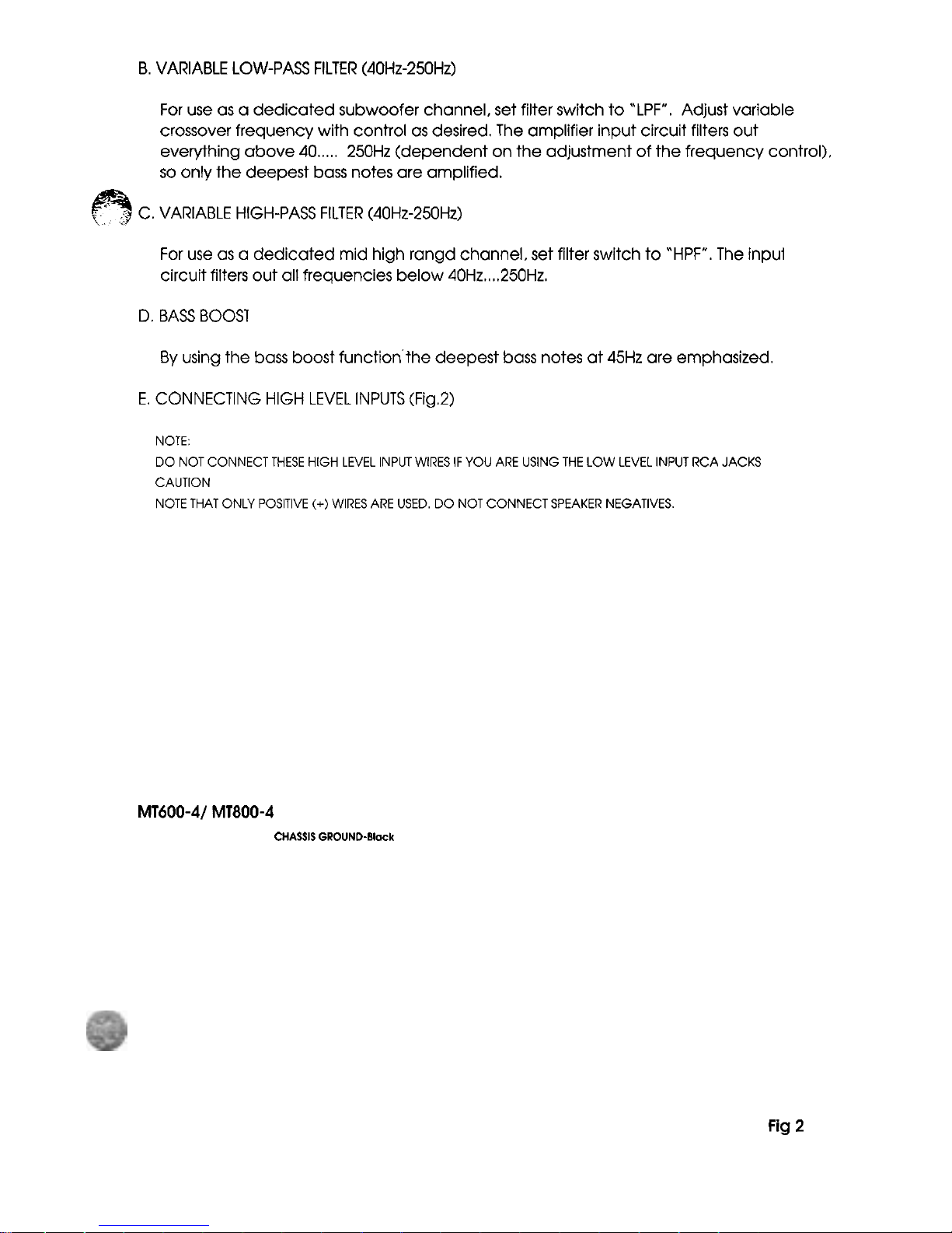
CONNECTING HIGH LEVEL INPUTS (Fig.2)
NOTE:
DO NOT CONNECT THESE HIGH LEVEL INPUT WIRES
IF
YOU ARE USING THE
LOW
LEVEL INPUT RCA JACKS
CAUTION
NOTE THAT ONLY POSITIVE
(+)
WIRES ARE USED. DO NOT CONNECT SPEAKER NEGATIVES.
MT600-41 MT800-4
CHASSIS
GROUND-Black
Fig
2
Page 6

F.
CONNECTING LOW LEVEL INPUTS (RCA Jacks)
NOTE:
DO NOT USE IN CONJUNCTION
WlTH HIGH LEVEL INPUT WIRES.
Wire routing is CRITICAL for NOISE
FREE
PERFORMANCE. Observe the following:
1.
Always use high quality RCA type shielded cables.
2.
Always use the shortest lenght possible. If the cable is too long, make an
*S"
type
loop (not a coiled loop) in the center of the cable to take up any excess.
3.
Never cut the shielded cable and re-splice it.
4.
Never route any Amplifier input cables near or parallel to speaker outputs, high
energy ignition wires, or near computer controlled ignition circuit units Computer
units may be found behind or under the dash panel in late model cars).
This METER LAMP will illuminate when the amplifier is turned "ON". If it fails to illuminate,
check the power connections to the Amplifier and fuses.
PROTECTION CIRCUIT
Should the Amplifier be "SHORT CIRCUITED" overloaded or overheated, the protect
circuit will "SHUT-DOWN" the Amplifier.
CAUTION
THIS AMPLIFIER IS DESIGNED TO OPERATE WlTH A MINIMUMLOAD IMPEDANCE OF 2 OHMS IN STEREO.
OR
4
OHMS IN MONO )BRIDGED, MULTI-MODE) CONFIGURATION.
SUBJECTING TO IMPEDANCE'S LOWER THAN RECOMMENDED, MAY CONSTITUTE TO POTENTIAL DAMAGE TO THE
MOSFET POWER SUPPLY. FOLLOW INSTRUCTIONS ON SECTION. "WIRING CONNECTIONS" FOR FURTHER
INFORMATION.
Page 7

In order to achieve maximum signal-to -noise performance, this control adjusts the signal
level from your Car
StereoISource, to match the Amplifier's sensitivity. It is NOT a volume
control.
To adjust, proceed as follows:
h
a Set INPUT LEVEL Control at mid-point.
b. Listen for audible distortion as you Increase the Car Stereo VOLUME control.
If
none
is heard, turn the adjustment level control toward to 'MAX" in stages, until the onset of
audible distortion is heard, then decrease to "MIN" level prior to the immediate
point of audible
distort~on.
c. If distortion is immediately heard, turn control to
'MIN"
until the sound is clear.
NOTE:
NOT
PERFORMING
ABOVE
ADJUSTMENT
PROCEDURE
AND/OR
SIMPLY
SETTING
THIS
CONTROL
AT
OR
NEAR
"MAX"
POSITION.
MAY
INDUCE
ELECTRICAL
AUDIO
NOISE
INTO
THE
SYSTEM.
SenSnMy
Control
Fig
3
Page 8

MT300-2 / MT400-2 / MT520-2 / MT820-2 / MT1200-2 / MT1600-2
(A)
STEREO MODE
(B)
MONO MODE
Page 9

(C) TRI MODE
TRI MODE OPEATIONAL OUTPUT allows a Crossover (Subwoofer) to be operated in MONO
mode while the main
speakera are playing in Stereo.
Leave the Crossover (Subwoofer) switch on "Full" positlon.
Use a
100
Volt, non-polar capacitor for a high pass crossover and a wire coil (inductor) to
block high frequencies from the Crossover (Subwoofer) as shown in the figure below.
Capacitor and inductor values as written in the below determine the crossover
-
frequencies.
The front and rear channels of this amplifier get this capability.
Only the rear left and right channels are shown below.
SUB
WOFER
4.8
0
RlOHT CHANNEL
4d
Ohm
COMPONENT VALUES FOR 6dB PASSIVE CROSSOVER
FREQUENCY
I
INDUCTOR
I
CAPACITOR
Page 10

Model: MT600-4 / MT800-4
(A)
4
CHANNEL MODE
m
3CH
24
Ohm
2.4
Mm
(8) 3 CHANNEL MODE
4
Ohm
24
Ohm
(C) 2 CHANNEL MODE
Page 11

(D) 6 CHANNEL MODE
COMPONENT VALUES FOR
6dB
PASSIVE CROSSOVER
FREQUENCY
80
Hz
INDUCTOR
7.5
mH
CAPACITOR
470
UF
Page 12

Check Audio Leads
an ohmmeter to check
sistance, please
that DC resistance and
ance may not be the
Page 13

Investigate the layour of you automobile thoroughly before drilling or cutting any holes.
Take care when you work near the thanks, lines, or hydraulic lines, and electrical wiring.
Don't mount this system so that the wire connections ate unprotected are subjectto
pinching or damage from nearby objects.
+
12V
DC power wire must be fused at the battery positive terminal connection.
-
Before making or breaking power connections at this ststem power terminals, disconnect
the
+12
V
wire at the battery end.
Confirm your
radiolcassette player and/or other equip is turned off while connectrng the
input jacks and speaker terminals.
If you need to replace the power fuse, replace it only with a fuse identical to that
supplied with the system. Using a fuse of different type or rating may result in damage to
this system which isn't covered by the warranty.
Page 14

FEATURES AND SPECIFICATIONS ARE SUBJECT TO CHANGE WITHOUT NOTICE.
LPF
Adjustable Sensitivity Range
Input
I
Low Level
Impedance
I
High
Level
Fuse
Dimension
(W
x H x L) : mm
40Hz-250Hz
0.2-1V
1
OK
Ohms
l00Ohms
15A
7.25 x 1 1.25
x
2.25
40Hz-250Hz
0.2-1V
10K
Ohms
100
Ohms
25A
8.5
x
1
1.25 x 2.25
40Hz-250Hz
0.2-1V
10K
Ohms
100
Ohms
40A
11.25 x 11.25
x2.25
40Hz-250Hz
0.2-1V
10K
Ohms
100
Ohms
25A x 2
14
x
11.25 x 2.25
40Hz-250Hz
0.2-1V
1
OK
Ohms
100
Ohms
30A x 2
20.5 x 11.25
x2.25
Page 15

FEATURES AND SPECIFICATIONS ARE SUBJECT TO CHANGE WITHOUT NOTICE.
 Loading...