

Page 1
VU METERTEMP METER
VU METER
VOLT METER
INSTALLATION & CONNECTIONS
Page 2
INSTALLATION & CONNECTIONS:
Before you begin, please take the time to read completely and understand all you
need to know in order to get the best performance out of your equipment.
First; understand what type of visual information the M-4 system provides.
Secondly, decide whether you want to install the system in cluster form (all meters
together) or in individual mounting brackets at various locations around your
vehicle. Assuming you have decided on the separate / individual mounting system,
where each meter is situated in various locations, the next steps are (a) locate &
identify each of the meters and each of the 4 separate / independent line-feeds –
one for each meter. Make sure to connect the correct feed-line to the appropriate
meter. (b) open the DIN chasis and carefully remove the larger control box; the box
would now be installed in the location of your choice. After you’ve done that, make
electrical connections as per the instructions below in “ELECTRICAL
CONNCETIONS” section.
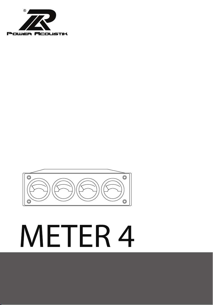
a) ISO DIN mounting: This type of installation is
exactly like installing a car stereo; make sure there’s
adequate space inside the dash cavity and avoid
severely disrupting existing wiring and connections
for other existing equipment. Make electrical
connections as per below in “ELECTRICAL
CONNECTIONS” section, while making sure that the
external data cable/wire and control box are securely
tucked–away.
Run a system-test before nalizing the install.
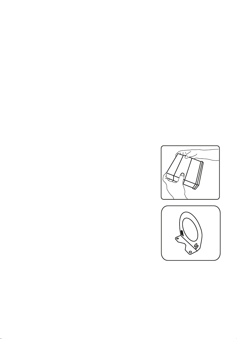
b) “ L”–bracket / under dash mounting: This type of
installation requires that you secure the L-bracket’s
mounting-ange to the under side of the dash or lip.
Do this with the self-tapping screws provided and
make sure that this action would not puncture or
disrupt existing wiring.
c) “A”–pillar mounting: This type of installation
requires that you secure the brackets to the A-pillar,
using the self-tapping screws provided. Please make
an extra eort to make sure that existing wires inside
the pillars would not be punctured or otherwise
aected by attaching the brackets.
Page 3

ELECTRICAL CONNECTIONS:
• Locate the GND (BLACK) wire and
connect it to the chassis of the
vehicle or the negative side of the
12 V DC power supply, if installed
in other than a vehicle. You may
use an AC adapter (preferably
regulated) , with the following
capacity;12 V @ 300 ma.
• Locate the B+ (RED) wire
connection and connect it to an
established + 12V DC source.
• Connect the Left RCA jack to the
Left signal source and the Right
RCA jack to the Right signal
source.
• Install the control-box(es) in a
location which allows for easy
access, in the event that
troubleshooting is necessary. Do
not situate the box in areas of the
vehicle where temperatures will
exceed 50 deg. C./122 deg. F..
• Please make sure that neither
the main input wire harness nor
the individual feed-lines are
stressed; as this may result in
premature cable breakage and
overall failure.
• Please make sure that a “snap”
sensation is realized when
inserting the connectors; this
ensures proper connection
between cable and control-box.
B+ (RED)
GND (BLACK)
-
+
12V DC POWER SUPPLU
R L
Page 4

WWW.POWERACOUSTIK.COM
 Loading...