

Page 1

Poulan PRO /
Instruction Manual
Manual de Instrucciones
Manuel d'lnstructions
SM132
For Occasional Use Only
WARNING:
Read and follow all Safety Rules and Operating Instructions before
using this product. Failure to do so can result in serious injury.
ADVERTENOIA:
Lea el manual de instrucciones y siga todas las advertencias e
instrucciones de seguridad. El no hacerlo puede resultar en le-
siones graves.
AVERTISSEMENT:
Lire le manuel d'instructions et bien respecter tousles avertisse-
ments et toutes les instructions de s6curite. Tout defaut de le
faire pourrait entraTner des blessures graves.
Electrolux Home Products, Inc.
1030 Stevens Creek Road
Augusta, GA 30907
The Electrolux Group. The worlds No.l choice.
KITCHEN, CLEANING AND OUTDOOR APPUANCES COMBINED
Copyright "_2004 Electrolux Home Products, Inc 530164890 11/19/04
Page 2

WARNING: When using gardening
appliances, basic safety precautions must al-
ways be followed to reduce the risk of fire and
serious injury. Read and follow all instruc-
tions.
This power unit can be dangerous! Operator is
responsible for following instructions and warn-
ings on unit and in manual. Read entire instruc-
tion manuat before using unit! Be thoroughIy fa-
miliar with the controls and the proper use of the
unit. Restrict the use of this unit to persons who
have read, understand, and will follow the
instructions and warnings on the unit and in the
manual. Never allow children to operate this
unit.
INSTRUCTION SAFETY INFORMATION
MANUAL ON THE UNIT
A
dBbDANGER: Never use blades or flail-
ing devices, This unit is designed for line trim-
mer use only, Use of any other accessories or
attachments wilt increase the risk of injury,
Q©O
A
WARNING: Trimmer line throws ob-
jects violently. You and others can be blinded/in-
jured, Wear eye and leg protection, Keep body
parts clear of rotating line.
Eye Protection
/ Hazard 7one
lm* Boots
Keep children, bystanders, and animals 50 feet
(15 meters) away, Stop unit immediately if ap-
proached.
if situations occur which are not covered in
this manual, use care and good judgment. If
you need assistance, contact your authorized
service dealer or call 1-800-554-6723,
OPERATOR SAFETY
• Dress properly. Always wear safety
glasses or similar eye protection when op-
erating, or performing maintenance, on
your unit (safety glasses are available).
Eye protection should be marked Z87.
• Alwayswear faceor dust mask if operation
is dusty.
• Always wear heavy, long pants, long sleeves,
boots, and gloves. Wearing safety leg guards
is recommended.
• Always wear foot protection. Do not go
barefoot or wear sandals. Stay clear of
spinning line.
• Secure hair above shoulder length. Secure
or remove loose clothing or clothing with
loosely hanging ties, straps, tassels, etc.
They can be caught in moving parts.
• Being fully covered also helps protect you
from debris and pieces of toxic plants
thrown by spinning line.
• Stay Alert. Do not operate this unit when
you are tired, ill, upset or under the influ-
ence of alcohol, drugs, or medication.
Watch what you are doing; use common
sense.
• Wear hearing protection.
• Never start or run inside a closed room or
building. Breathing exhaust fumes can kill
• Keep handles free of oil and fuel.
UNIT / MAINTENANCE SAFETY
• Disconnect the spark plug before perform-
ing maintenance except carburetor adjust-
ments,
• Look for and replace damaged or loose
parts before each use. Look for and repair
fuel leaks before use. Keep in good working
condition.
• Reptace trimmer head parts that are
chipped, cracked, broken, or damaged in
any other way before using the unit.
• Maintain unit according to recommended
procedures. Keep cutting line at proper
length.
• Use only 0.080" (2 mm) diameter Poulan
PRO_) brand replacement line. Never use
wire, rope. string, etc.
• install required shield properly before using
the unit. Use only specified trimmer head;
make sure itis properly installed and securely
fastened.
• Make sure unit is assembled correctly as
shown in this manual.
• Make carburetor adjustments with lower
end supported to prevent line from contact-
ing any object.
• Keepothersawaywhen makingcarburetor
adjustments.
• Use only recommended Poulan PRO ¢ ac-
cessories and replacement parts.
• Have all maintenance and service not ex-
plained in this manual performed by an au-
thorized service dealer.
FUEL SAFETY
• Mix and pour fuel outdoors.
• Keep away from sparks or flames.
• Use a container approved for fuel.
• Do not smoke or allow smoking near fuel or
the unit.
• Avoid spilling fuel or oil. Wipe up all fuel
spills.
• Move at least 10 feet (3 meters) away from
fueling site before starting engine.
• Stop engine and allow to cool before re-
moving fuel cap.
• Always store gasoline in a container ap-
proved for flammable liquids.
2
Page 3

CUTTINGSAFETY
_ WARNING: Inspect the area before
each use. Remove objects (rocks, broken
glass, nails, wire, etc.) which can be thrown
by or become entangled h_ line. Hard objects
can damage the trimmer head and be thrown
causing serious injury.
• Use only for trimming, scalping, mowing and
sweeping. Do not use for edging, pruning or
hedge trimming.
• Keep firm footing and betance. Do not over-
reach.
• Keep alt parts of your body away from muffler
and spinning Hne. Keep engine below waist
level. A hot muffler can cause serious bums.
• Cut from your teff to your right. Cutting on
right side of the shield will throw debris away
from the operator=
• Use only in daylight or good artificial light.
• Use only for jobs explained in this manual.
TRANSPORTING AND STORAGE
• Allow engh_e to cool before storing or trans-
porting in vehicle.
• Emptythe fueItank before storing or trans-
porting the unit. Use up fuel left in the carbu-
retor by starting the engine and tetth_g it run
until it stops.
• Store unit and fuel in areawhere fuelvapors
cannot reach sparks or open flames from
water heaters, etectric motors or switches,
furnaces, etc.
• Store unit so line limiter blade cannot acci-
dentally cause injury, The unit can be hung
by the shaft.
• Store unit out of reach of children,
SAFETY NOTICE: Exposure to vibrations
through prolonged use of gasoline powered
hand tools could cause blood vessel or nerve
damage in the fingers, hands, and joints of
people prone to circulation disorders or ab-
normal swellings. Pro;onged use in cold
weather has been linked to blood vessel dam-
age in otherwise healthy people. If symptoms
occur such as numbness, pain, loss of
strength, change in skin color or texture, or
loss of feeling in the fingers, hands, or joints,
discontinue the use of this tool and seek med-
ical attention, An anti-vibration system does
not guarantee the avoidance of these prob-
lems. Users who operate power tools on a
continual and regular basis must monitor
closely their physical condition and the condi-
tion of this toot,
SPECIAL NOTICE: This unit is equipped
with a temperature limiting muffler and spark
arresting screen which meets the require-
ments of California Codes 4442 and 4443. All
U.S. forest land and the states of California,
idaho, Maine, Minnesota, New Jersey, Ore-
gon, and Washington require by law that
many internal combustion engines be
equipped with a spark arresting screen. Ifyou
operate in a locale where such regulations ex-
ist, you are legally responsible for maintaining
the operating condition of these parts. Failure
to do so is a vio;ation of the law. For normal
homeowner use, the muffler and spark arrest-
ing screen will not require any service. After
50 hours of use, we recommend that your
muffler be serviced or repiaced by an autho-
rized service dealer.
dDbWAHNINL_: If received assembted,
repeat alt steps to ensure your unit is properly
assembled and all fasteners are secure.
Examine parts for damage. Do not use dam-
aged parts.
NOTE: If you need assistance or find parts
missing or damaged, call 1-800-554-6723.
It is normal for the fuel filter to rattle in the
empty fuel tank.
Finding fuel or oil residue on muffler is normal
due to carburetor adjustments and testing
done by the manufacturer.
ADJUSTING THE HANDLE
WAR NIN G: When adjusting the assist
handle, be sure it remains above the safety label
and below the mark or arrow on the shaft.
1. Loosen wing nut on handle.
2. Rotate the handle on the shaft to an upright
position; retighten wing nut,
ATTACHING SHIELD
,_ WARNING: The shield must be prop-
erly installed. The shield provides partial protec-
tion to the operator and others from the risk of
thrown objects, and is equipped with a line limit-
er blade which cuts excess line to the prober
length. The line limiter blade (on underside of
shield) is sharp and can cut you.
For proper orientation of shield, see KNOW
YOUR TRIMMER illustration in OPERATION
section,
1. Remove wing nut from shield,
2. Insert bracket into slot as shown,
3. Pivot shield until bolt passes through hole
in bracket.
4. Securely tighten wing nut onto bolt,
Slot Wing Nut
Shield
PIVOT
Bracket
Page 4
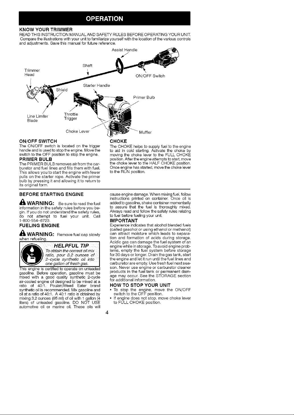
KNOWYOURTRIMMER
READTHIS INSTRUCTION MANUALAND SAFETY RULESBEFORE OPERATINGYOUR UNIT
Compare the iliustrationswith your unit to familiarize yourself with the location of the various controls
and edjustrnents. Save this manual for future reference.
Assist Handle
/
Shaft
Trimmer
Head
Starter Handle
Shield
Line Umiter Throttle
Blade Trigger
ON/OFF Switch
Primer Bulb
Choke Lever
ON/OFF SWITCH
The ON/OFF switch is located on the trigger
handle and is used to stop the engine. Move the
switch to the OFF position to stop the engine.
PRIMER BULB
The PRIMER BULB removes air from the car-
buretor and fueI lines and fills them with fuel.
This atlows you to start the engine with fewer
pulis on the starter rope. Activate the primer
bulb by pressing it and allowing it to return to
its original form.
BEFORE STARTING ENGINE
_ WARNING: Be sure to read the fuel
information in the safety rules before you be-
gin. If you do not understand the safety rules,
do not attempt to fuel your unit. Call
1-800-554-6723.
FUELING ENGINE
_ WARNING: Remove fuel cap slowly
when refueling.
HELPFUL TIP I
\ To obtain th e correct oilmix I
ratio, pour 8.2 ounces of I
• 2-cycle synthetic oil into I
one gallon of fresh gas. I
This engine
gasoline. Before operation, gasoline must be
mixed with a good quality synthetic 2-cycle
air-cooled engine oil designed to be mixed at a
ratio of 40:1. Poulan/Weed Eater brand
synthetic oil is recommended, Mix gasoline and
oil at a ratio of 40:1. A 40:1 ratio is obtained by
mixing 3.2 ounces (95 mI) of oil with 1 gallon (4
liters) of unleaded gasoline, DO NOT USE
automotive oil or marine oil. These oils will
is certified to operate on unleaded
Muffler
CHOKE
The CHOKE he_ps to supply fuel to the engine
to aid in cold starting. Activate the choke by
moving the choke lever to the FULL CHOKE
position. After the engine attempts to start, move
the choke lever to the HALF CHOKE position,
Once engine has started, move the choke lever
to the RUN position,
cause engine damage. When mixing fuel, follow
instructions printed on container. Once oil is
added to gasoline, shake container momentarily
to assure that the fuel is thoroughly mixed,
Always read and follow the safety rules relating
to fuel before fueling your unit.
IMPORTANT
Experience indicates that alcohol blended fuels
(called gasohot or using ethanol or methanol)
can attract moisture which leads to separa-
tion and formation of acids during storage,
Acidic gas can damage the fuel system of an
engine white in storage. To avoid engine prob-
lems, empty the fuel system before storage
for 30 days or tonger. Drain the gas tank, start
the engine and let it run until the fuel lines and
carburetor are empty, Use fresh fuel next sea-
son. Never use engine or carburetor cleaner
products in the fuel tank or permanent dam-
age may occur, See the STORAGE section
for additional information,
HOW TO STOP YOUR UNIT
• To stop the engine, move the ON/OFF
switch to the OFF position,
• If engine does not stop, move choke lever
to FULL CHOKE position,
Page 5
ON/OFFSwitch
HOW TO START YOUR UNIT
_WARNING: The trimmer head will
turn while starting the engine. Avoid any con-
tact with the muffler. A hot muffler can cause
serious burns.
HELPFUL TIP I
!f your engine still does not
I stait after foflowing these I
instructions, please Carl
1-800-554-6728.
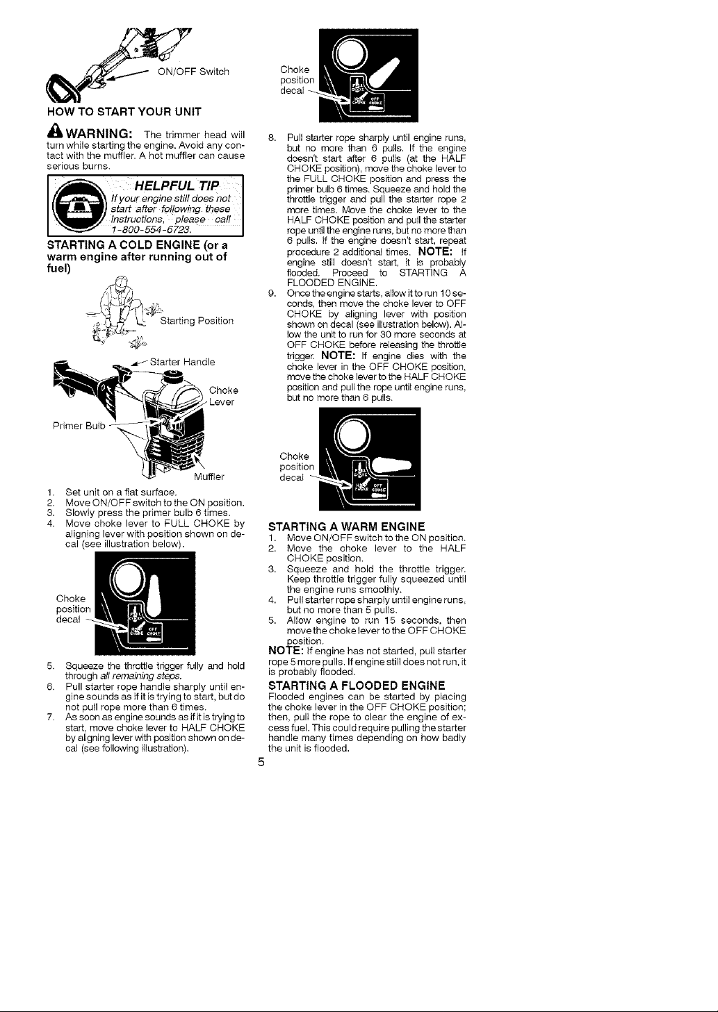
STARTING A COLD ENGINE (or a
warm engine after running out of
fuel)
,_ Starting Position
Choke
_Lever
Primer Bulb
Muffler
1,
Set unit on a flat surface.
2.
Move ON/OFF switch to the ON position.
3.
Slowly press the primer bulb 6 times.
4.
Move choke lever to FULL CHOKE by
aligning lever with position shown on de-
cal (see illustration below).
Choke
position
decat
5. Squeeze the throttle trigger fully and hold
through all remaining steps,
6. Pull starter rope handle sharply until en-
gine sounds as if it is trying to start, but do
not pull rope more than 6 times.
7. As soon as engine sounds as ifit is trying to
start, move choke lever to HALF CHOKE
by aligning lever with position shown on de-
cal (see following illustration).
Choke
position
decal
8. Pull starter rope sharply until engine runs.
but no more than 6 pulls. If the engine
doesn't start after 6 pulls (at the HALF
CHOKE position), move the choke lever to
the FULL CHOKE position and press the
primer bulb 6 times. Squeeze and hold the
throttle trigger and pull the starter rope 2
more times. Move the choke lever to the
HALF CHOKE position and pull the starter
rope until the engine runs. but no more than
6 pulis, if the engine doesn't start, repeat
procedure 2 additional times. NOTE: if
engine still doesn't start, it is probably
flooded. Proceed to STARTING A
FLOODED ENGINE.
9. Once the engine starts, allow itto run 10 se-
conds, then move the choke lever to OFF
CHOKE by aligning lever with position
shown on decal (see illustration below). AF
tow the unit to run for 30 more seconds at
OFF CHOKE before releasing the throttle
trigger. NOTE: If engine dies with the
choke lever in the OFF CHOKE position.
move the choke lever to the HALF CHOKE
position and pull the rope until engine runs.
but no more than 6 pulls.
Choke
position
decal
STARTING A WARM ENGINE
1. Move ON/OFF switch to the ON position.
2. Move the choke lever to the HALF
CHOKE position.
3. Squeeze and hold the throttle trigger.
Keep throttle trigger fully squeezed until
the engine runs smoothly.
4. Pull starter rope sharply until engine runs.
but no more than 5 pulls.
5. Allow engine to run 15 seconds, then
movethe choke lever to the OFF CHOKE
position.
NOTE: if engine has not started, pull starter
rope 5 more pulls. If engine still does not run. it
is probably flooded.
STARTING A FLOODED ENGINE
Flooded engines can be started by placing
the choke lever in the OFF CHOKE position;
then, pull the rope to clear the engine of ex-
cess fuel. This could require pulling the starter
handle many times depending on how badly
the unit is flooded.
5
Page 6
If theunitstilldoesn'tstart,referto
TROUBLESHOOTINGTABLEor call
1-800-554-6723.
OPERATING INSTRUCTIONS
It is recommended that the engine not be
operated for longer than 1 minute at full
throttle.
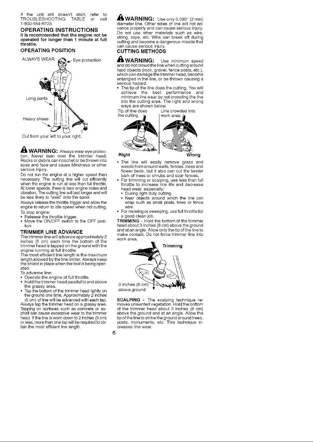
OPERATING POSITION
ALWAYS WEAR: _._ Eye protection
Long pant_.
Heavy shoes
Out from your left to your right.
A
44, WAR NIN G: Alwaysweareye protec-
tion. Never lean over the trimmer head.
Rocks or debris can ricochet or be thrown into
eyes and face and cause blindness or other
serious injury.
De net run the engine at a higher speed than
necessary. The cutting line will cut efficiently
when the engine is run at less than full throttle.
At lower speeds, there is less engine noise and
vibration. The cutting line will last longer and will
be tess likely to 'Weld" onto the spool.
Always release the throttie tdgger and allow the
engine to return to idle speed when not cutting.
To stop engine:
• Release the throttle trigger.
• Move the ON/OFF switch to the OFF posi-
tion.
TRIMMER LINE ADVANCE
The trimmer line will advance approximately 2
inches (5 cm) each time the bottom of the
trimmer head is tapped on the ground with the
engine running at full throttle.
The most efficient line length is the maximum
length allowed by the line limiter. Always keep
the shield in place when the tool is being oper-
ated.
To advance line:
• Operate the engine at full throttle.
• Holdthetrimmerhead paralieltoandabove
the grassy area.
• Tap the bottom of the trimmer head lightly on
the ground one time. Approximately 2 inches
(5 cm) of line will be advanced with each tap.
Always tap the trimmer head on a grassy area.
Tapping on surfaces such as concrete or as-
phalt can cause excessive wear to the trimmer
head. If the line is worn down to 2 inches (5 cm)
or less, more than one tap will be required to ob-
tain the most efficient line length.
A
WARNING: use only0,080" (2mm)
diameter line. Other sizes of line will not ad-
vance properly and can cause serious injury.
Do not use other materials such as wire,
string, rope, etc. Wire can break off during
cutting and become a dangerous missile that
can cause serious injury.
CUTTING METHODS
'_L,WARNING: Use mh_imum speed
and do not crowd the line when cutting around
hard objects (rock, graveI, fence posts, etc.),
which can damage the trimmer head, become
entangled in the Ih_e, or be thrown causing a
serious hazard.
• The tip of the line does the cutting. You will
achieve the best performance and
minimum line wear by not crowding the line
into the cutting area. The right and wrong
ways are shown below.
Tip of iine does Line crowded into
the cutth_g.
Right W_'ong
• The line will easily remove grass and
weeds from around wails, fences, trees and
flower beds, but it also can cut the tender
bark of trees or shrubs and scar fences.
• For trimming or scalping, use less than full
throttle to increase line life and decrease
head wear, especially:
• During light duty cutting.
• Near objects around which the line can
wrap such as small posts, trees or fence
wire.
• Formowingorsweeping, usefullthrottlefor
a good clean job.
TRIMMING - Hold the bottom of the trimmer
head about 3 inches (8 cm) above the ground
and at an angle. Allow only the tip of the line to
make contact. De net force trimmer line into
work area.
Trimming
3 inches (8 crr
above ground
SCALPING - The scalping technique re-
moves unwanted vegetation. Hold the bottom
of the trimmer head about 3 inches (8 cm)
above the ground and at an angle. Allow the
tip of the lineto strike the ground around trees,
posts, monuments, etc. This technique in-
creases line wear.
6
Page 7
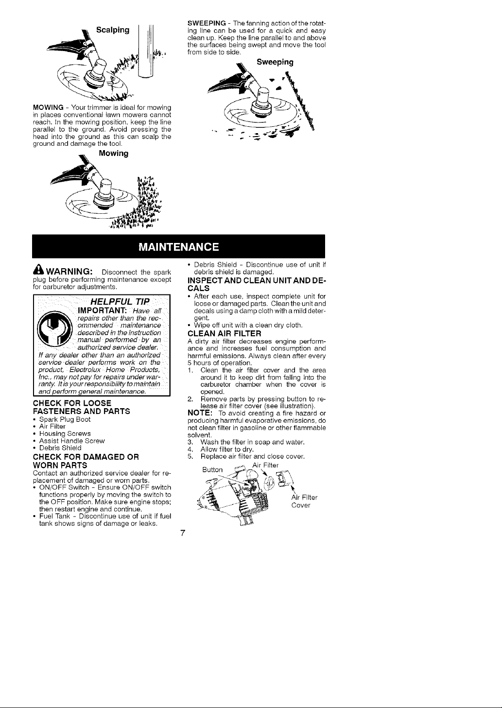
Scalping
MOWING - Your trimmer is ideal for mowing
in places conventional lawn mowers cannot
reach. In the mowing position, keep the line
parallel to the ground. Avoid pressing the
head into the ground as this can scalp the
ground and damage the tool.
Mowing
SWEEPING - The fanning action of the rotat-
ing line can be used for a quick and easy
clean up. Keep the line parallel to and above
the surfaces being swept and move the tool
from side to side.
Sweeping
4E_W/-XHNIN_: Disconnect the spark
plug before performing maintenance except
for carburetor adjustments.
HELPFUL TIP
_ IMPORTANT: Hav e all
fh_l_ll_X, repairs other than the rec-
I_ _ _ ommended maintenance
_1_ .,_/ described in the instruction
",_I_ _Vj" manual performed by an
If any dealer other than an authorized
Service dealer performs work On the
product, Electrolux Home Products,
Inc., may not pay for repairs under war-
ranty. It is your responsibility to maintain
and perform general maintenance.
CHECK FOR LOOSE
FASTENERS AND PARTS
• Spark Plug Boot
• Air Filter
• Housing Screws
• Assist Handle Screw
• Debris Shield
CHECK FOR DAMAGED OR
WORN PARTS
Contact an authorized service dealer for re-
placement of damaged or worn parts.
• ON/OFF Switch - Ensure ON/OFF switch
functions properly by moving the switch to
the OFF position. Make sure engine stops;
then restart engine and continue.
• Fuel Tank - Discontinue use of unit if fuel
tank shows signs of damage or leaks.
authorized service dealer.
• Debris Shield - Discontinue use of unit if
debris shield is damaged.
INSPECT AND CLEAN UNIT AND DE-
CALS
• After each use. inspect complete unit for
loose or damaged parts. Clean the unit and
decals using a damp cloth with a mild deter-
gent.
• Wipe off unit with a clean dry cloth.
CLEAN AIR FILTER
A dirty air filter decreases engh_e perform-
ance and increases fuel consumption and
harmful emissions. Always clean after every
5 hours of operation.
1. Clean the air filter cover and the area
around it to keep dirt from falling into the
carburetor chamber when the cover is
opened.
2. Remove parts by pressing button to re-
lease air filter cover (see illustration).
NOTE: To avoid creating a fire hazard or
producing harmful evaporative emissions, do
not clean filter in gasoline or other flammable
solvent.
3. Wash the filter in soap and water.
4. Allow filter to dry.
5. Replace air filter and close cover.
Button _-, _. _,
_'_ _ Cover
_>_ Air Filter
"_X-_ Air Filter
Page 8

MUFFLER AND SPARK ARREST-
ING SCREEN
WARNING: The muffler on this prod-
uct contains chemicals known to the State of
California to cause cancer.
As your unit is used, carbon deposits build up
on the muffler and spark arresting screen.
For normal homeowner use, however, the
muffler and spark arresting screen wilt not re-
quire any service. After 50 hours of use, we
recommend that your muffler be serviced or
replaced by your authorized service dealer.
REPLACE SPARK PLUG
Replace the spark plug each year to ensure
the engine starts easier and runs better. Set
spark plug gap at 0.025 inch (0.6 mm). Igni-
tion timing is fixed and nonadjustable.
1. Twist, then pull off spark plug boot.
2. Remove spark plug from cylinder and
discard.
3. Replace with Champion RCJ-6Y spark
plug and tighten securely with a 3/4 inch
(19 mm) socket wrench.
4. Reinstall the spark plug boot.
REPLACING THE LINE
1. Remove spool by firmly pulling on tap
button.
2. Clean entire surface of hub and spool.
3. Replace with a pre-wound spool, or cut two
lengths of 12-1/2 feet of 0.080" (2 mm) di-
ameter Poulen PRO ¢ brand line.
_IWARNING: Never use wire. rope,
string, etc.. which can break offand become a
dangerous missile.
4. Insert ends of the lines about 1/2 inch (1
cm) into the small holes on the inside of
spool.
/7- ? ,
/f )'/l_ Holes
Line exit holes Line in Notch
\
_, Line in Notch
Hub
5. Wind the line evenly and tightly onto the
spool. Wind in the direction of the arrows
found on the spool.
6. Push the lines into the notches, leaving 3
to 5 inches (7 - 12 cm) unwound.
7. Insert the lines into the the exit holes in
the hub as shown in the illustration.
8. Align the notches with the line exit holes.
9. Push spoo_ into hub until it snaps into
place.
10. Pull the lines extending outside of the hub
to release the lines from the notches.
REPLACING THE TRIMMER HEAD
1. Align t_o_ein the dust cup with the hoie in
the side of the gearbox by rotating the
dust cup.
Insert a small screwdriver into aligned
holes. This will keep the shaft from turning
while removing and installing the trimmer
head.
Screwdriver__
3. While hoiding the screwdriver in position,
remove trimmer head by turning clock-
wise.
4. Thread replacement trimmer head onto
the shaft by turning counterclockwise.
Tighten until secure.
5. Remove the screwdriver.
CARBURETOR ADJUSTMENT
WARNING: Keepothers away when
making idle speed adjustments. The trimmer
head will be spinning during this procedure,
Wear your protective equipment and observe
all safety precautions.
The carburetor has been carefully set at the
factory, Adjustments may be necessary ifyou
notice any of the following conditions:
• Engine will not idle when the throttle is
released.
Make adjustments with the unit supported so
the cutting attachment is off the ground and
will not make contact with any object. Hold
the unit by hand while running and making ad-
justments. Keep all parts of your body away
from the cutting attachment and muffler.
Idle Speed Adjustment
Allow engine to idle, Adjust speed until engine
runs without stalling (idle speed toe slow),
• Turn idle speed screw clockwise to increase
engine speed if engine stalls or dies.
• Turn idle speed screw counterclockwise to
decrease engine speed,
Page 9

Cover
AirFilter_d
IdleSpeed
Screw
Ifyourequirefurtherassistanceorareunsure
aboutperformingthisprocedure,contactan
authorizedservicedealeror call
1-800-554-6723.
,tA
_"mWARNING: Perform the following
steps after each use:
• Allow engine to cool before storing or trans-
porting.
• Store unit and fuel h_awell ventilated area
where fuel vapors cannot reach sparks or
open flames from water heaters, electric
motors or switches, furnaces, etc.
• Store unit with all guards in place. Position
unit so that any sharp object cannot acci-
dentally cause injury.
• Store unit and fuel well out of the reach of
children.
SEASONAL STORAGE
Prepare unit for storage at end of season or if
it will not be used for 30 days or more.
If your unit is to be stored for a period of time:
• Clean the entire unit before lengthy
storage.
• Store in a clean dry area.
• Lightly oil external metal surfaces.
FUEL SYSTEM
Under FUELING ENGINE in the OPERA-
TION section of this manual, see message la-
beled IMPORTANT regarding the use of ga-
sohol in your engine.
Fuel stabilizer is an acceptable alternative in
minimizing the formation of fuel gum deposits
during storage. Add stabilizer to the gasoline
in the fuel tank or fue_ storage container. Fol-
low the mix instructions found on stabilizer
container. Run engine at least 5 minutes after
adding stabilizer.
HELPFUL TIP I
_el_ oitmixture theoilwillsepa-
_ rate from the gas.
m_) We recommend that you I
_ shake the gas can weekly
ENGINE
• Remove spark plug and pour 1 teaspoon of
40:1,2-cycle engine oil (air cooled) through
the spark plug opening. Slowly pull the
starter rope 8 to 10 times to distribute oil.
• Replace spark plug with new one of recom-
mended type and heat range.
• Clean air filter.
• Check entire unit for loose screws, nuts,
and bolts. Replace any damaged, broken,
or worn parts,
• At the beginning of the next season, use
only fresh fuel having the proper gasoline to
oil ratio.
OTHER
• Do not store gasoline from one season to
another.
• Replace your gasoline can if it starts to rust.
During storage of your gas/ I
to insure proper blending of I
the gas and oil. I
Page 10
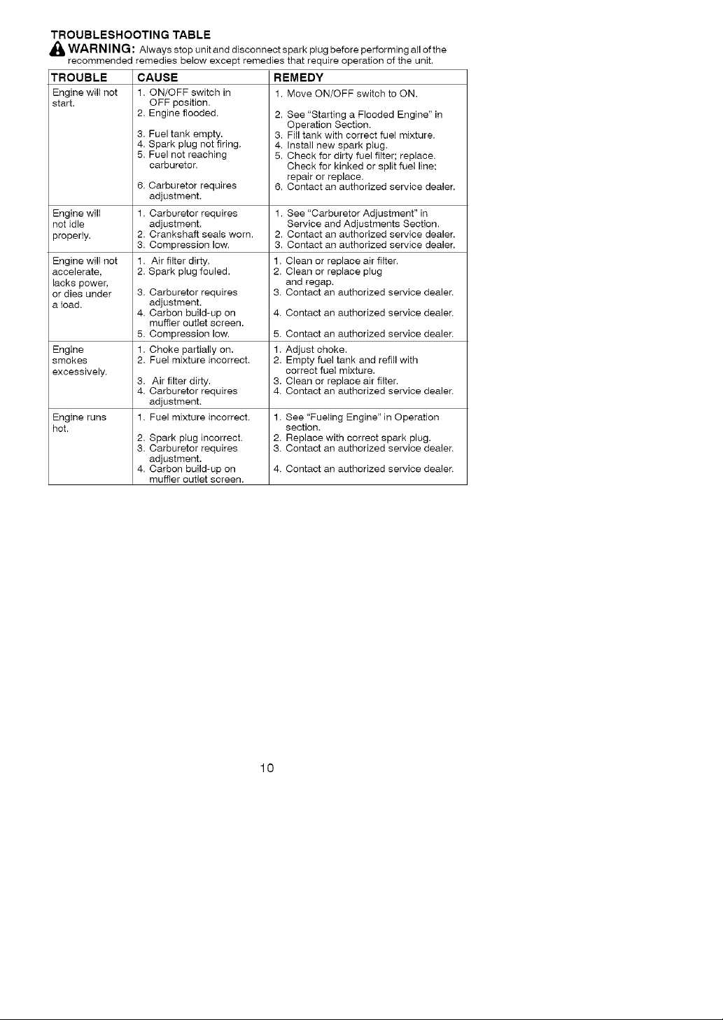
TROUBLESHOOTING TABLE
_l WARN IN : Always stop unit anddisconnect spark plugbefore performing allofthe
G
recommended remedies below except remedies that require operation of the unit.
TROUBLE
Engine will not
start.
Engine will
not idle
properly.
Engine wilt not
accelerate,
lacks power,
or dies under
a load,
Engine
smokes
excessively,
Engine runs
hot.
CAUSE
1. ON/OFF switch in
OFF position.
2. Engine flooded,
3. Fuel tank empty.
4. Spark plug not firing.
5. Fuel not reaching
carburetor.
6. Carburetor requires
adjustment.
1. Carburetor requires
adjustment.
2. Crankshaft seals worn.
3. Compression low.
1. Air filter dirty.
2. Spark plug fouled.
3. Carburetor requires
adjustment.
4. Carbon build-up on
muffter outIet screen.
5. Compression low.
1. Choke partially on.
2. Fuel mixture incorrect.
3. Air filter dirty.
4. Carburetor requires
adjustment.
1. Fuel mixture incorrect.
2. Spark plug incorrect.
3. Carburetor requires
adjustment.
4. Carbon build-up on
muffier outIet screen.
REMEDY
1. Move ON/OFF switch to ON.
2. See "Starting a Flooded Engine" in
Operation Section.
3. Fill tank with correct fuel mixture.
4. Install new spark plug.
5. Check for dirty fuel filter; replace.
Check for kinked or split fuel line;
repair or replace.
6. Contact an authorized service dealer.
1. See "Carburetor Adjustment" in
Service and Adjustments Section.
2. Contact an authorized service dealer.
3. Contact an authorized service dealer.
1. Clean or replace air filter.
2. Clean or replace plug
and regap.
3. Contact an authorized service dealer.
4. Contact an authorized service dealer.
5. Contact an authorized service dealer.
1. Adjust choke.
2. Empty fuel tank and refill with
correct fuel mixture.
3. Clean or replace air filter.
4. Contact an authorized service dealer.
1.
See "Fueting Engine" in Operation
section.
2.
Replace with correct spark plug.
3.
Contact an authorized service dealer.
4.
Contact an authorized service dealer.
10
Page 11

ELECTROLUX HOME PRODUCTS, INC.,
warrants to the original purchaser that each
new Poulan PRO@ brand gasoline toot or at-
tachment is free from defects in material and
workmanship and agrees to repair or replace
under this warranty any defective gasoline
product or attachment as follows from the
originat date of purchase.
2 YEARS- Parts and Labor, when used for
household purposes.
90 DAYS - Parts and Labor, when used for
commercial, professional, or income produc-
ing purposes.
30 DAYS - Parts and Labor, if used for rental
purposes.
This warranty is not transferable and does not
cover damage or liability caused by improper
handling, improper maintenance, or the use
of accessories and/or attachments not spe-
cifically recommended by ELECTROLUX
HOME PRODUCTS, INC., for this tool. Addi-
tionally, this warranty does not cover tune-
ups, spark plugs, filters, cutting line, or rotat-
ing head parts that will wear and require
replacement with reasonable use during the
warranty period, This warranty does not coy-
er predelivery setup or normal adjustments
explained in the instruction manual.
THIS WARRANTY GIVES YOU SPECIFIC
LEGAL RIGHTS, AND YOU MAY HAVE
OTHER RIGHTS WHICH VARY FROM
STATE TO STATE.
NO CLAIMS FOR CONSEQUENTIAL OR
OTHER DAMAGES WILL BE ALLOWED,
AND THERE ARE NO OTHER EXPRESS
WARRANTIES EXCEPT THOSE EX-
PRESSLY STIPULATED HEREIN.
SOME STATES DO NOT ALLOW LIMITA-
TIONS ON HOW LONG AN IMPLIED WAR-
RANTY LASTS OR THE EXCLUSION OR
LIMITATIONS OF INCIDENTAL OR CON-
SEQUENTIAL DAMAGES, SO THE ABOVE
LIMITATIONS OR EXCLUSION MAY NOT
APPLY TO YOU.
The policy of ELECTROLUX HOME PROD-
UCTS, INC., is to continuously improve its
products. Therefore, ELEOTROLUX HOME
PRODUCTS, INC., reserves the right to
change, modify, or discontinue models, de-
signs, specifications, and accessories of all
products at any time without notice or obliga-
tion to any purchaser.
YOUR WARRANTY RIGHTS AND OBUGA-
TIONS: The U.S, Environmental Protection
Agency, California Air Resources Board, and
ELECTROLUX HOME PRODUCTS, INC., are
pleased to explain the emissions control system
warranty on your year 2002-2004 small off-
road engine, in California, all small off-road en-
gines must be designed, built, and equipped to
meet the State's stringent anti-smog standards.
ELECTROLUX HOME PRODUCTS, INC.,
must warrant the emission control system on
your small off-road engine for the periods of
time listed below provided there has been no
abuse, neglect, or improper maintenance of
your small off-road engine. Your emission con-
trol system includes parts such as the carbure-
tor and the ignition system, Where a warrant-
able condition exists, ELECTROLUX HOME
PRODUCTS, INC,, will repair your smail off-
road engine engine at no cost to you, Expenses
covered under warranty include diagnosis,
parts and labor. MANUFACTURER'S WAR-
RANTY COVERAGE: if any emissions related
part on your engine (as listed under Emissions
Control Warranty Parts List) is defective or a de-
fect in the materials or workmanship of the en-
gine causes the failure of such an emission re-
iated part, the part will be repaired or replaced
by ELECTROLUX HOME PRODUCTS, INC.
OWNER'S WARRANTY RESPONSlBIU-
TIES: As the small off-road engine engine own-
er, you are responsible for the performance of
the required maintenance listed in your instruc-
tion manual. ELECTROLUX HOME PROD-
UCTS, INC., recommends that you retain all re-
ceipts covering maintenance on your small
off-road engine, but ELECTROLUX HOME
PRODUCTS, INC., cannot deny warranty sole-
ly for the lack of receipts or for your failure to en-
sure the peffon-nance of all scheduled mainte-
nance. As the small off-road engine engine
owner, you should be aware that ELECTRO-
LUX HOME PRODUCTS, INC., may deny you
warranty coverage ifyour small off-road engine
engine or a part of it has failed due to abuse, ne-
glect, improper maintenance, unapproved mod-
ifications, or the use of parts not made or ap-
proved by the original equipment manufacturer.
You are responsible for presenting your small
off-road engine to an ELECTROLUX HOME
PRODUCTS, INC., authorized repair center as
soon as a problem exists. Warranty repairs
should be completed in a reasonable amount of
time, not to exceed 30 days. If you have any
questions regarding your warranty rights and re-
sponsibilities, you should contact your nearest
authorized service center or call ELECTRO-
LUX HOME PRODUCTS, INC., at
1-800-554-6723. WARRANTY COM-
MENCEMENT DATE: The warranty period be-
gins on the date the small off-road engine is
purchased. LENGTH OF COVERAGE: This
warranty shall be for a period of two years from
the initial date of purchase. WHAT IS COV-
ERED: REPAIR OR REPLACEMENT OF
PARTS. Repair or replacement of any war-
ranted part will be performed at no charge to the
owner at an approved ELECTROLUX HOME
PRODUCTS, iNC,, servicing center, if you
have any questions regarding your warranty
11
Page 12
rights and responsibilities, you should contact
your nearest authorized service center or call
ELECTROLUX HOME PRODUCTS, INC., at
1-800-554-6723. WARRANTY PERIOD: Any
warranted part which is not scheduled for re-
placement as required maintenance, or which is
scheduled only for regular inspection to the ef-
fect of "repair or replace as necessary" shall be
warranted for 2 years. Any warranted part which
is scheduled for replacement as required main-
tenance shall be warranted for the period of time
up to the first scheduled replacement point for
that part. DIAGNOSIS: The owner shall not be
charged for diagnostic labor which leads to the
determination that a warranted part is defective
if the diagnostic work is performed at an ap-
proved ELECTROLUX HOME PRODUCTS,
INC., servicing center. CONSEQUENTIAL
DAMAGES: ELECTROLUX HOME PROD-
UCTS, IND., may be liable for damages to other
engine components caused by the failure of a
warranted part stiff under warranty. WHAT IS
NOT COVERED: All failures caused by abuse,
neglect, or improper maintenance are not cov-
ered. ADD-ON OR MODIFIED PARTS: The
use of add-on or modified parts can be grounds
for disallowing a warranty claim. ELECTRO-
LUX HOME PRODUCTS, INC., is not liable to
cover failures of warranted parts caused by the
use of add-on or modified parts. HOW TO FILE
A CLAIM: If you have any questions regarding
your warranty rights and responsibilities, you
should contact your nearest authorized service
center or caII ELECTROLUX HOME PROD-
UCTS, INC., at 1-800-554-6723. WHERE TO
GET WARRANTY SERVICE: Warranty ser-
vices or repairs shall be provided at all ELEC-
TROLUX HOME PRODUCTS, INC., service
centers. Call: 1-800-554-6723. MAINTE-
NANCE, REPLACEMENT AND REPAIR OF
EMISSION RELATED PARTS: Any ELEC-
TROLUX HOME PRODUCTS, INC., approved
replacement part used in the performance of
any warranty maintenance or repair on emis-
sion related parts will be provided without
charge to the owner ifthe part is under warranty.
EMISSION CONTROL WARRANTY PARTS
LIST: Carburetor, Ignition System: Spark Plug
(covered up to maintenance schedule), Ignition
Module, Muffler including catalyst. MAINTE-
NANCE STATEMENT: The owner is responsi-
ble for the performance of all required mainte-
nance as defined in the instruction
manu-
al.
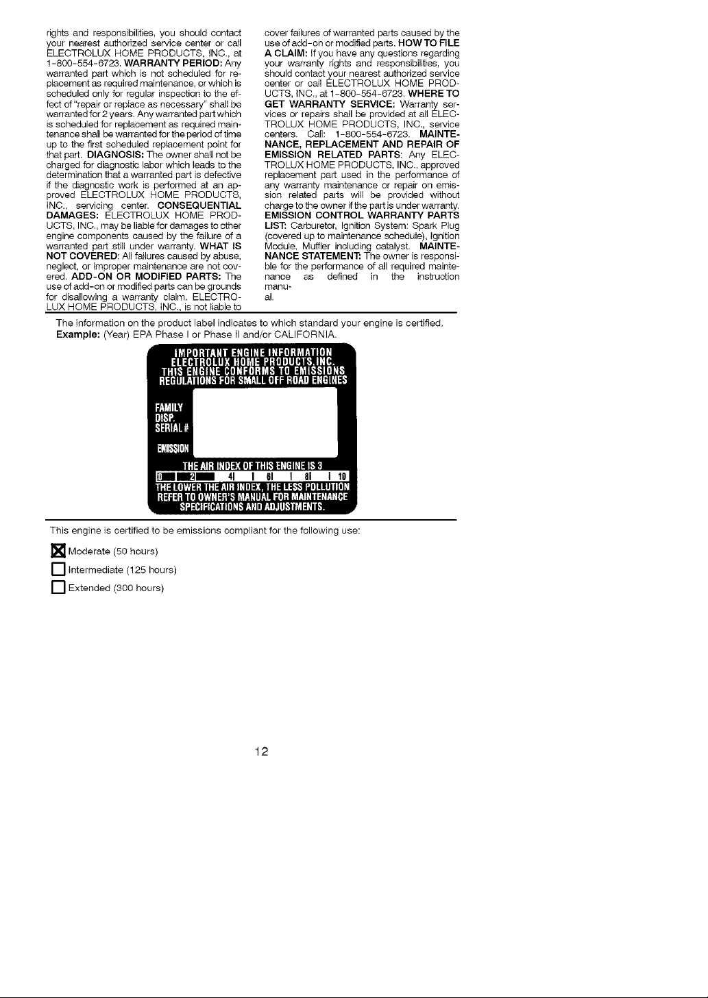
The information on the product label indicates to which standard your engine is certified.
Example: (Year) EPA Phase I or Phase II and/or CALIFORNIA.
41 I GI I 81 1
This engine is certified to be emissions compliant for the following use:
[] Moderate (50 hours)
[] Intermediate (125 hours)
[] Extended (300 hours)
12
Page 13

ADVERTENClA:AI usar cualquier
herramienta de fuerza de jardineria, deberAn ob-
servarse precauciones bAsicas de seguirdad en
todo momento para reducir el riesgo de incendio
y graves heridas. Lea y cumpla con todas las
instrucciones.
iEsta herramienta de fuerza puede ser peli-
grosa! Cabe al usuario le responsabilidad de
cumplir con todas las advertencias e instruc-
ciones, iLea el manual de instrucciones en su
totalidad antes de usar el aparato! Este com-
pletamente familiarizado con los controIes y
con eI uso correcto del aparato. Umite el uso
de este aparato a aquellas personas que hay-
an leido y comprendido, y que vayan a ob-
edecer, todas las advertencias e h_struc-
ciones tanto en el aparato como en el manual.
No permita nunca a los ni(_os que usen este
aparato.
MANUAL DE INFORMACION
INSTRUCCIONES DE SEGURIDAD
A
PELIGRO: Nunca use cuchillas nidis-
positivos desgranadores. El aparato fue dis-
eifiado para ser usado exclusivamente como
cortodora de linea. El uso de cualquier otro
pieza o accessorio incrementarA el petigro de
heridas.
DEL APARATO
Q
_ADVERTENClA: La linea de eorte
arroja objetos violentamente. Usted, at igual
que otras personas, puede quedar ciego o
herido. Use anteojos de seguridad y protec-
cion en las piernas. Mantenga todas las
partes del cuerpo alejadas de la linea girante.
Use anteojos de seguridad
Mantenga a los niSos, los espectadores y aei-
males a una distancia minima de 15 metros
(50 pies). Pare el motor inmediatamente si al-
guien se le acerca.
Si acontece alguna situaci6n no prevista en este
manual, tenga cuidado y use buen criterio. Si ne-
cesita ayuda, entre en contacto con su distribui-
dot autorizado del servicio o Ilame al
1-800-554-6723.
SEGURIDAD DEL USUARIO
• Vistase apropiadamente. Siempre use an-
teojos de seguridad o similar protecci6n
para los ojos cuando use o de mantenimien-
to a este aparato (anteojos de seguridad
est#tn disponiMes). La proteccion para los
ojos debe estar marcada Z87.
• Siempre utilize mascarilla para ta cara o
mascarilla a prueba de polvo si se va a tra-
bajar en condiciones donde hay polvo.
• Siempre utilize pantalones pesados y lar-
gos, mangas largas, botas y guantes. Se re-
comienda el uso de pantorrilleras de seguri-
dad.
• Siempre utilize protecci6n para los pies. No
trabaje descalzo ni en sanda)ias. Evite la
linea girante.
• Mantenga el cabello por encima de los hom-
bros, atandolo para tal efecto si es necesa-
rio. No use ropa suelta ni ropa con corbatas,
tiras, borlas, etc. que cuelgan libremente.
Pueden enredarse en las piezas en movi-
miento.
• Siesta completament tapado, estar#t mas
protegido de los escombros y pedazos de
plantas t6xicos arrojados per la lieea gi-
rante.
• Mantengase alert& No haga use del apara-
to estando cansado, enfermo, trastornado o
bajo ta influencia del alcohol, de drogas o de
remedios. Vigile bien Io que est#t haciendo;
use del sentido comt_n.
• Use protecci6n de oidos.
• Nunca ponga el aparato en marcha ni Io
deje en marcha dentro de un recinto cerra-
do. Respirar los vapores del combustible Io
puede matar.
• Mantenga las manijas libres de aceite y de
combustible.
SEGURIDAD DEL APARATO Y EN
EL MANTENIMIENTO
• Desconecte la bujia antes de hacer cualqui-
er mantenimiento menos los ajustes al car-
burador.
• Inspeccione el aparato y cambie las piezas
daSadas o flojas antes de cada uso. Repare
toda fuga de combustible antes de usar el
aparato. Mantenga el aparato en buenas
condiciones de use.
• Cambie todas las piezas del cabezal que
estee descantilladas, resquebrajadas, que-
bradas o da{_adas de cualquier otro modo,
antes de usar el aparato.
• Haga el mantenimiento del aparato de
acuerdo a los procedimientos recomend-
ados. Mantenga la linea de corte el largo
aprodiado.
• Use soIamente linea de diametro 2 mm (0,080
de pulgada) de la marca Poulae PRO ®. Nun-
ca use alambre, soga, hilo, etc.
• Instale ta protector requerida antes de usar
su aparato. Use la bobina especificada.
AsegOrese que la bobina este correcta-
mente instalada y este bien fijo.
13
Page 14

• AsegQrese que el aparato este correcta-
mente armado como se muestra en el
manual.
• Haga los ajustes al carburador con el cabe-
zal apoyado de modo que ta linea no pueda
tocar nada.
• Mantenga alejadas a las demas personas
siempre que haga ajustes al carburador.
• Use exclusivamente los accesorios y repues-
tos Poulan PRO ¢ recomendados.
• Todo servicio y mantinimiento no explicado
en este manual debera ser efectuado por un
distribuidor autorizado del servicio.
SEGURIDAD CON EL COMBUSTIBLE
• Mezcle y vierta el combustible al aire libre.
• Mantengalo alejado de las chispas y de las
llamas.
• Use recipiente aprobado para el combus-
tible.
• No fume ni permita que se fume cerca de1
combustible ni del aparato ni mientras este
este en uso.
• Evite derramar e} combustible o el aceite.
Umpie rode el combustib}e derramado.
• AIAjese a per Io menos 3 metros (10 pies)
de1lugar de abastecimiento antes de poner
en marcha el motor.
• Pare el motor y permita que se enfrie el apa-
rato antes de retirar la tapa del tanque.
• AlmacAne siempre combustible en un reci-
piente aprobado para los liquidos inflama-
bles.
SEGURIDAD AL CORTAR
_ ADVERTENOIA: InsFeccione et
Area antes de cada use. Retire los objetos (pie-
dras, vidrio roto, ciavos, alambre, etc.) que se
puedan enredar en la linea o que esta pueda ar-
rojar. Los objetos duros pueden da(_ar el cabezal
y este los puede arrojar, causando graves heri-
das.
• Use el aparato exclusivamente para recortar,
para cortar cesped y para barrer. No _o use
para cortar bordes, para podar ni para recortar
sere.
• Mantenga el equi_ibrio, con los pies en una
superficie estable. No se extienda demasia-
do.
• Mantenga todas las partes del cuerpo aleja-
das de la iinea girante y dei silenciador.
Mantenga el motor por debajo del nivel de la
cintura. El silenciador puede causar graves
quemaduras cuando esta caiiente.
• Corte siempre de izquierdaa derecha. Sise
corta con la linea del lado derecho del protec-
tor, los escombros volaran en sentido opuesto
al usuario.
• Use el aparato t_nicamente de dia o en iuz
artificial fuerte.
• Utilice el aparato solamente para ias tareas
explicadas en este manual.
TRANSPORTE Y ALMACENAMIENTO
• Espere que el motor se enfrie y fije bien el
aparato antes de quardarlo o de transpor-
tado en un vehicuio.
• Vacie el tanque de combustible antes de guar-
dar el aparato o de transportarIo. Consuma
todo el combustible restante en el carburador
poniendo el motor en marcha y dejandolo en
marcha hasta que le motor se pare solo.
• Guarde el aparato y el combustible en un lu-
gar donde los vapores del combustible no
puedan alcanzar chispas ni llamas prove-
nientes de los termotanques, los motores o
interruptores elActricos, los calefactores
centrales, etc.
• Guarde el aparato de modo que el cuchilla
limitadora de linea no pueda causar heridas
accidentales. Se puede coigar el aparato
pot ia caja el eje de propulsion.
• Guarde el aparato fuera del alcance de los
nti_os.
AVlSO SPECIAL: El estar expuesto alas
vibraciones a traves del uso prolongado de
herramientas de fuerza a gasolina puede cua-
sar daf_os a los vasos sanguineos o a los ner-
vios de los dedos, las manos y ias coyunturas
en aquellas personas que tienen propensidad
a los trastornos de la circulaciAn o alas hin-
chazones anormales. El uso prolongado en
tiempo frio ha sido asociado con da(fos a los
vasos snaguineos de personas que por otra
parte se encuentran en perfecto estado de sa-
lud. Si ocurren sintomas tales como el entu-
mecimiento, el dolor, la fatta de fuerza, los
cambios en el color o la textura de la piel o falta
de sentido en los dedos, ias manos o ias coy-
unturas, deje de usar esta maquina inmedia-
tamente y procure atenciAn medica. Los siste-
mas de anti-vibraciAn no garantizan que se
eviten tales problemes. Los usuarios que ha-
cen uso continuo y prolongando de las herra-
mientas de fuerza deben fiscalizar atenta-
mente su estado fisico y el estado del aparato.
AVlSO ESPECIAL: Su aparato viene equi-
pada con silenciador limitador de temperatura y
con rejilia antichispa que cumpla los requisitos
de los Codigos de California 4442 y 4443. Todas
las tierras forestadas federales, mas los estados
de California, Idaho, Maine, Minnesota, Nueva
Jersey, Washington y Oregon, requieren por ley
que muchos motores de combustiAn interna es-
tan equipados con rejilla antichispa. Si usted el
aparato en un estado y otra Iocalidad donde ex-
isten tales reglamentos, usted tiene la responsa-
bilidad juridica de mantener estas piezas en cor-
recto estado de funcionamiento. De io contrario,
estara en infraccion de ia ley. Para el uso normal
del due5o de la casa, el silenciador y la rejilla
antichispa no requeriran ningLin servicio.
Despues de 50 horas de uso, recomendamos
que ai silenciador se ie de servicio o sea
substituido por un distribuidor autodzado del ser-
vicio.
14
Page 15

4"LADVERTENClA: Si recibio el apa-
rato ya armado, repita todos los pasos para
asegurar que el mismo se encuentre correcta-
mente armado y que todos los fijadores se en-
cuentren bien ajustados.
Examh_e 1aspiezas para verificar que no haya
da{_os. No use piezas daSadas.
AVlSO: Si necisita ayuda, si faltan piezas o
si hay piezas da[_adas, 1lame al nOmero
1-800-554-6723.
Es normal escuchar que el filtro de combstiMe
golpetee en el tanque vacio.
Es normal encontrar residuos de aceite o de
gasolh_a en el silenciador, debido a los ajustes
al carburador y a las pruebas efectuadas pot
el fabricante.
AJUSTE DEL MANGO
_ADVERTENOIA: AI ajustar laman-
go auxiliar, asegOrese que este se mantenga
sobre la etiqueta de seguridad y debajo la
marca o la flecha en el eje.
1. Afloje la tuerca mafiposa en el mango.
2. Gire el mango en posici6n vertical. Vuelva
a apretar la tuerca mariposa firmemente.
INSTALACION DE LA PROTECTOR
,_ ADVERTENCIA: El protector deb-
er#. ser instalado correctamente. El protector
provee protecci6n parcial hacia el usuafio y
otras personas contra el riesgo de los objetos
arrojados, y viene equipado con un cuchiHa
limitadora de linea que corta el exceso de
line& El cuchilla limitadora de tinea (en la
parte h_ferior del protector) es filoso y puede
cortar. Para conseguir la orientaci6n apropiada
para el protector, vea la ilustraci6n CONOZCA
SU APARATO que se encuentra en la secci6n
de USO.
1. Remueva latuerca mariposade la protec-
tor.
2. Introduzca el soporte dentro de la ranura
como se muestra.
3. Haga girar la protector basra que eltorniF
Io pase a traves del hueco en el soporte.
4. Apriete firmemente la tuerca mariposa en
el tornillo.
Ranura de alas
Protector
tuerca en forma
PIVOTE Caja de
engranajes
CONOZCASUAPARATO
LEA ESTE MANUAL DE INSTRUCCIONES Y LAS REGLAS DE SEGURIDAD ANTES DE
PONER EL APARATO EN MARCHA. Compare las ilustraciones con su aparato para familiari-
zarse con la ubicacion de los diversos controles y ajustes. G uarde este manuat para uso futuro.
Mango Auxiliar
J
Eje
Cabezal de Corte '_
Protector x_
Cuchilla Gatillo Acelerador
Umitadora
de Linea
Palanca del
Cebador
Mango de la Cuerda ON/OFF
de Arranque
15
Interruptor
Bombeador
Silenciador
Page 16

INTERRUPTOR ON/OFF
Se usa el interruptor ON/OFF para detener el
motor. Coloque el interruptor ON/OFF en laposi-
ci6n OFF para detener el motor.
BOMBEADOR
El BOMBEADOR retira el mire de el carbura-
dory de las lineas de combustible y las Ilena
de mezcla de combustible, permiti_,ndole pon-
er el motor en marcha con menos tirones de la
cuerda de arranque. Accione el bombeador
oprimiendolo y luego dejando que este re-
cobre su forma original
ANTES DE PONER EN MARCHA EL
MOTOR
,_ ADVERTENCIA: Lea atentamente
la informaci6n sobre el combustible en laas
reglas de seguridad antes de comenzar. Si no
comprende las reglas de seguridad, no intente
abastecer el aparato de combustible. Llame al
nQmero 1-800-554-6723.
ABASTECIMIENTO DEL MOTOR
_ ADVERTENCIA: Remueva la tapa
del tanque de combustible lentamente al rea-
bastecer combustible.
INFORMAOION UTIL ]
Para obtonor la proporcidn I
correcta de mezcla de I
aceite vierta 8,2 onzae de I
aceite sintetico de 2 ciclo s I
Este motor est& habilitado para funcionar con
gasolina sin plomo. Antes de comenzar con el
uso, se deber& mezclar la gasolina con un
aceite de sintetico de buena calidad para mo-
tores de 2 tiempos enfriados a aire. Recomen-
damos el aceite de sintetico de la marca Pou-
lan/Weed Eater. Mezcle la gasolina con eI
aceite en la proporci6n 40:1. Se obtiene una
proporci6n de 40:1 mezctando 3,2 onzas (95
ml) de aceite con cada gal6n (4 litros) de gaso-
lina sin plomo. NO USE aceite para au-
tom6viles ni para barcas. Estos aceites
daffar&n el motor. AI mezclar el combustible,
siga las instrucciones impresas en el reci-
piente. Una vez haya afiadido el aceite a la ga-
soiina, agite al recipiente brevemente para
asegurar que el combustible este completa-
mente mezclado. Siempre lea y siga las
instrucciones de seguridad que tienen que ver
con el combustible antes de abastecer el apa-
rato.
IMPORTANTE
La experiencia indica que los combustible
mezclados con alcohol (los Ilamados gasohol
o los que contienen etanol o metanol) pueden
atraer la humedad, Io que puede causar la se-
paracion y la formacion de &.cidos durante el
almacenaje. La gasolina acida puede dai_ar el
sistema de combustible deI motor durante el
almacenaje. Para evitar problemas con el mo-
dentro de gaeotina fresca. J
CEBADOR
El CEBADOR ayuda a suministrar combus-
tible al motor para facilitar el arranque cuando
el motor est&. frio. Acione el cebador coiocan-
do la palanca en la posici6n FULL CHOKE.
Despues que el motor intente arrancar, mue-
va la palanca del cebador a la posicion HALF
CHOKE. Despues que el motor se haya
puesto en marcha, ponga la palanca de1 ceba-
dor en la posicion RUN.
tor, deber_, vaciarse el sistema de combus-
tible antes de almacenar el aparato por 30
dims o mb.s. Vacie el tanque de combustible,
ponga el motor en marcha y d6jelo en marcha
hasta que las lineas de combustible y el car-
burador queden vacios. Use combustible
fresco para la pr6xima temporada. Nunca use
productos de limpieza de motor o carburador
en el tanque de combustible ya que de hacerla
puede provocar daf_os permanentes. Vea la
secci6n de ALMACENAJE para informaci6n
adicional.
PARA DETENER EL MOTOR
• Para detener el motor, mueva el interruptor
ON/OFF a la posici6n OFR
• Si el motor no se detiene, mueva la palanca
det cebador a la posici6n FULL CHOKE.
Interruptor
ON/OFF
PARA PONER EN MARCHA
EL MOTOR
_bADVERTENCIA: El cabezal de
corte girar&, mientras se este intentando poner
en marcha et motor. Evite el hacer ningL_n tipo
de contacto con el silenciador. Un silenciador
caliente podria provocar quemaduras de gra-
vedad sise toca.
_ INFORMACION UTIL I
Si el motor de su aparato I
no se pusiera en marcha I
despu#s de haber seguido
estas instrucciones, flam e
PARA ARRANCAR CON MOTOR
FRIO (o motor caliente despues de
quedar sin combustible)
al 1-800-554-5723.
16
Page 17

Mango de la Cuerda
de Arranque
Palanca
del
Cebador
Bombeador
1. Ponga el aparato en una superficie plana.
2. Mueva el interruptor ON/OFF a la posi-
ci6n ON.
3. Optima tentamente el bombeador 6
veoes.
4. Mueva la palanca dei cebador a FULL
CHOKE alineando la palaeca en la posici6n
mostrada en la etiqueta (yea la iiustraci6n
abajo).
Etiqueta
muestra
la
posici6n
de1
cebador
5. Apdete y sujete el gatillo durante todos Ice
paeoe siguientee.
6. Tire firmemente det mango de ta cuerda
de arranque hasta que el motor suene
como s ieste intentando arrancar, pero no
tire de la cuerda m_.s de 6 veces.
7. Tan pronto como el motor suene como si
fuera a arrancar, mueva la palanca del ce-
bador a HALF CHOKE alineando la palan-
ca en la posici6n mostrada en la etiqueta
Etiqueta
muestra
la
posici6n
de1
cebador
Tire firmemente dei mango de ia cuerda
de arranque hasta que el motor arranque,
pero no mas de 6 tirones. Si el motor no
arranca despues del sexto tir6n de la
cuerda de arranque (con ia palanca de1
cebador en la posici6n HALF CHOKE),
mueva la paianca del cebador a la posi-
ci6n FULL CHOKE y oprima el bombea-
dot 6 veces. Apriete y sostenga et gatillo
acelerador y tire de la cuerda de arranque
otras 2 veces. Mueva la palanca dei ceba-
Silenciador
dora la posicion HALF CHOKE y tire de la
cuerda de arranque hasta que el motor se
ponga en marcha, pero no mas de 6
veces. Si el motor no arranca, repita el
procedimiento de arranque otras 2 veces
adicionales. AVISO: Si el motor no ar-
ranca, probablemente se encuentre aho-
gado. Proceda con la secci6n ARRAN-
QUE DE MOTOR AHOGADO.
g,
Una vez que el motor arranca, permita
que el motor marche por 10 segundos,
luego mueva la palanca del cebador a
OFF CHOKE alineaedo la palanca en la
posici6n mostrada en la etiqueta (vea la
ilustraci6n abajo). Permita que el motor
marcha por 30 segundos con la palanca
del cebador en la posicion OFF CHOKE
antes de soltar el gatillo acelerador.
AVISO: Si el motor se apaga con la pa-
lanca del cebador en la posici6n OFF
CHOKE, mueva la palanca a la posici6n
HALF CHOKE y tire de la cuerda de ar-
ranque hasta que el motor se ponga en
marcha, pero no mas de 6 tirones.
Etiqueta
muestra
la
posici6n
del
cebador
PARA ARRANCAR CON EL MOTOR
CALIENTE
1. Mueva el interruptor ON/OFF a ta posi-
ci6n ON.
2. Mueva la palanca del cebador a la posi-
ci6n HALF CHOKE.
3. Oprima y sostenga el gatillo acelerador.
Mantenga el gatillo totaimente oprimido
hasta que el motor marche sin problemas.
4. Tire firmemente del mango de la cuerda
de arranque hasta que el motor se ponga
en marcha, pero no mb.s de 5 tirones.
5. Permita que el motor marche por 15 segun-
dos, entonces mueva la palaeca del ceba-
dora la posicion OFF CHOKE.
AVISO: Si el motor no arranca, tire de la cuer-
da otras 5 veces. Si el motor no arranca, pro-
babiemente este ahogado.
ARRANQUE DE MOTOR AHOGADO
Lors motores ahogados pueden ponerse en
marcha moviendo la palanca del cebador a la
posici6n OFF CHOKE; luego, tirede lacuerda
para aclarar el exceso de combustible. Esto
podr_t requerir que se tire del mango de la
cuerda muchas veces dependiendo cuan
ahogado se encuentre el motor.
Si el aparato sigue sin ponerse en marcha,
vea la TABLA DIAGNOSTICA o Ilame al
nt_mero 1-800-554-6723.
17
Page 18

INSTRUCCIONESDE USO
Se recomienda que no opere el motor pot
mas de un minuto a la velocidad maxima.
POSIClON DE USO
USE SIEMPRE: PretecciAn
Pantalones
Largos _ (
Zapatos
Gruesos
Corte izquierda a derecha.
_ADVERTENCIA: Usesiemprepro-
tecciAn para los ojos. Nunca se inclh_e por en-
cima del cabezal. La linea puede arrojar o
hacer rebotar piedras o desechos hacia los
ojos y la cara, pudieedo causar la perdida de
la vista u otras graves heridas.
No haga marchar el motor a revoluciones mas
altas que las necesarias. La linea de corte cor-
tara de una forma mAs eficiente sin que el motor
este acelerado a fondo. A revoluciones mas ba-
jas, habrA menos ruido y menor vibraciAn del
motor. La linea de corte durara mAs tiempo y
tendrA menor probabilidad de"fundirse" en la bo-
bina.
Siempre que no se halle cortando, suelte el
gatillo acelerador y permita que el motor vuel-
va a marcha tent&
Para detener el motor:
• Sueite el gatiHo acelerador.
• Mueva el interrupter ON/OFF a la posiciAn
ON.
AVANCE DE LA LINEA DE CORTE
La linea de corte avanza aproximadameete 5
cm (2 pulgadas) cada vez que se toca eI cabe-
zal contra el suelo con el motor acelerado a
fondo.
EI largo mas eficiente de la linea es el largo
mbximo permitido per el limitador de
linea.Siempre mantenga ia cubierta protectora
en su lugar siempre que el aparato este en uso.
Para avanzar la lieea:
• Acelere el motor a fondo.
• Sostenga el cabezal paralelo al suelo, por en-
cima de un Area con cesped.
• Toque el cabezal de corte contra el suelo le-
vemente una vez. Con cada toque, la linea
avanzarA aproximadamente 5 cm (2 pulga-
das).
Toque el cabezal contra el sueto siempre en
un Area con cesped. Si se hace tocar contra
superficies como el cemento o el asfalto, el
cabezal podria sufrir desgaste excesivo.
Si la linea se ha gastado y cuenta con 5 cm (2
pulgadas) o menos, hara falta mAs de un toque
para obtener el largo de lieea mas eficiente.
de ojos
'_ADVERTENCIA: Use Qnicamente
iinea con diAmetro de 2 mm (0,080 de pulgada).
Las lineas de otros diArnetros no avanzarAn de-
bidamente y pueden causar graves heridas. No
use otros materiales, tales, como el alambre, el
hilo, la cuerda, etc. El alambre se puede quebrar
al cortar, convirtiendose en un misil muy peligro-
so y causando heridas de gravedad.
METODOS DE CORTE
'_ADVERTENCIA: Use lavelocidad
minima y no acerque el aparato demasiado al
cortar cerca de objetos solidos (piedra, graviF
la, postes, etc.): estos pueden daAar el cabe-
zal, pueden enredarse en la linea o la lieea los
puede arrojar violentamente al aire, causando
serio peligro.
• La punta de la linea es la que corta. Se con-
seguirA mejor rendimiento y el minimo des-
gaste si no se mete la tieea dentro del mate-
riai que se estA cortando. La ilustraciAn a
continuacion muestra la forma correcta e in-
oorreota de oortar.
La punta de la linea La linea esta metida
es la que corta, dentro del material
Correcta Incorre'cta
• La linea retira f&cilmente el cAsped y las malas
hierbas de alrededor de paredes, cercados,
Arboles y macizos de flores; pero tambien es
capaz de cortar la corteza tierna de arboles y
arbustos y de marcar las cercas.
• Para recortar o escalpar, use el aparato sin
acelerar a fondo, para incrementar la vida
Otilde la linea y disminuir el desgaste dei ca-
bezal, especialmente:
• AI hacer trabajos livianos.
• Cerca de objetos con los cuales la linea se
puede enredar, como son los postes o
Arboles de poco diametro y el alambre de
las oercas.
• Paracortarcespedybarrer, acelereel motora
fondo para Iograr un buen trabajo de Iimpieza.
PARA REOORTAR - Sostenga el cabezal
unos 8 cm (3 pulgadas) del suelo yen Angulo.
Unicamente la punta de ta linea deberA hacerel
contacto con el materiaI a cortar. No meta la
linea deetro del Area que se estA cortaedo.
Para Recortar
8 cm (3 pulga-
das) del suelo
18
Page 19

PAPA ESCALPAR - La t6cnica de1 ascalpa-
do retira la vegetaci6n no deseada abajo a la
tierra. Sostenga el cabezal unos 8 cm (3 pul-
gadas) del suelo yen angulo. Deje que la
punta de la linea go_pee contra el suelo cerca
de los arboles, los postes, los monumentos,
etc. Esta tecnica incrementa el desgaste de la
linea.
Para Escalpar
PAPA CORTAR CESPED - Este parato es
idea1 para cortar cesped en lugares donde las
cortadoras convencionales no Ilegan. En po-
sici6n de cortar cesped, mantenga la lieea pa-
ralela al suelo. Evite presioear el cabezal con-
tra el suelo, ya que de hacerlo podria escalpar
la vegetacion y da_ar el aparato.
Para Cortar Cesped
PAPA BARRER - Se puede usar la acci6n
ventiladora de la linea girante para barrer rApida
y f_tcilmente un Area determinada. Mantenga la
linea paralela al suelo directamente encima de
las superficies que se quiera barrer y meuva el
aparato de un lado al otro rapidamente.
Para Barter
_ADVERTENCIA: Desconecte la
buj[a antes de hacer cualquier mantenimiento,
con la excepcion de los ajustes al carburador.
INFORMACION UTIL
IMPORTANTE: Permita
que toda reparaal6n que no
i sea el mantenimiento te-
l comendado en el manual
de instrucalones sea efec-
tuada pot un distribuidor
Si un distdbuidor NO autorizado efec-
tuara cualqaler trabajo en el producto,
Electrolux Home Products, inc., no pa-
gara reparaciones bajo ta garantia. Es su
reeponeabilidad el mantener y efectuar el
mantenimiento general del producto.
VERIFIQUE QUE NO HAYA FIJA-
DOPES NI PIEZAS SUELTAS
• Cubierta de _aBujia
• Filtro de Aire
• Tornillos de la Caja
• Tornillo del Mango Auxiliar
• Protector
VERIFIQUE QUE NO HAYA PIEZAS
DANADAS O GASTADAS
Entre en contacto con el distribuidor autoriza-
do del servicio para el reemplazo de piezas
dal_adas o desgastadas.
autorizado dal servicio.
• Interruptor ON/OFF - AsegOrese de que el
interruptor ON/OFF este funcionando cor-
rectamente coloc_tndoio en la posici6n O FR
AsegOrese de que ei motor se haya deteni-
do por completo, luego, ponga el motor en
marcha nuevamente y continQe.
• Tanque de Combustible - Deje de usar el
aparato si hay se[_ales de daSos o perididas
en el tanque de combustible.
• Protector - Deje de usar el aparato si el pro-
tector esta daSado.
INSPECCIONE Y LIMPIE EL APARA-
TO Y SUS PLACAS
• Despues de que cada uso, inspeccione la
aparato completa para saber si hay piezas
flojas o dal_adas. Limpie eI aparato y las
placas usando un trapo hLimedo con un de-
tergente suave.
• Seque el aparato usando un trapo seco y
limpio.
LIMPIE EL FILTRO DEL AIRE
Los fi_tros de aire sucios disminuyen la vida
t_tily el rendimiento del motor e iecrementan el
cons umo de combustible y de emiciones noci-
vas. Umpie siempre el filtro de aire despues
de cada 5 horas de uso.
1. Limpie la tapa del filtro de aire y el area aF
rededor de la tapa para evitar que caiga
suciedad o desechos en el carburador
cuando se abre la tapa.
2. Remueva las piezas presionando el bot6n
para aflojar la tapa del filtor de aire (vea la
ilustracion).
19
Page 20

AVISO: Para evitar peligro de incendio y de
emiciones evaporativas nocivas, no limpie el
filtro de aire con gasoliea ni cualquier otro sol-
vente inflamable.
3. Umpie el filtro con agua y jab6n.
4. Permita que elfiltro se seque.
5. lestaie el filtro de aire y cierra la tapa.
Boton
SILENCIADOR Y LA REJILLA ANTI-
CHISPAS
Filtro de aire
Tapa det
Fiitro de Aire
_.ADVERTENCIA: Elsilenciader en
este producto contiene 1assubstancias quimi-
casque el estado de California reconoce
oomo oausantes de cancer.
A medida que se use el aparato, el silenciador
y la rejilla aetichispas se van carbonizando.
Para el uso normal dei dueSo de la casa, sin
embargo, el silenciador y la rejilla antichispa no
requeriran ningOn servicio. Despues de 50
horas de use, recomendamos que al siienciador
se le de servicio o sea substituido pot un distri-
buidor autorizado de1servicio.
CAMBIE LA BUJIA
Debera cambiarse la bujia anualmente para
asegurar que el motor arranque facilmente y
tenga un mejor rendimeinto. Ajuste la separa-
cion de los electrodos a0,6 mm (0,025 de pul-
gada). El encendido es fijo e inalterable.
1. Gire y saque la cubierta de la bujia.
2. Retire ta bujia det cilindro y desechela.
3. C_tmbiela per una bujia Champion RCJ-6Y
y ajuste firmemente la bujia nueva con una
Ilave de cubo de 19 mm (3/4 de pulgada).
4. Instale nuevamente la cubierta de la
bujia.
REEMPLAZO DE LA LINEA DE
CORTE
1. Retire la bobina tirando de_bot6n detoque
firmemente.
2. Umpie por entero la superficie del cubo y
de la bobina.
3. Reemplace la bobina por una previa-
mente enrollada, o corte dos pedazos de
aproximadamente 3,8 metros (t2-1/2
pies) de largo de linea de 2 mm (0.080 de
pulgada) de la marca Poulan PRO ®.
_ ADVERTENCIA: Nunca use
alambre, cuerda, hilo, etc., los cuales pueden
romperse y convertirse en proyectiles peligro-
SOS.
4. letroduzca tas puntas de la linea, alrede-
dorde 1 cm (1/2 puigada), dentro deI hue-
cos pequeSo que se encuentra en la parte
interior de la bobina.
Bobina _ /_/,_ _ _ Huecos
_S/,_/ ' Peque(Sos
Huecos de salida de la linea
Linea dentro de la muesca
J' Linea dentro de ia muesca
Cube
5. Enrolle la Iinea en la bobina de forma pa-
reja y ajustada. Enrolle la linea en la direc-
ci6n en que apuntan tas flechas que se
encuentran en la bobina.
6. Introduzca la linea dentro de las mues-
cas, dejando de 7 a 12 cm (3 a 5 puiga-
das) sin enrollar.
7. Introduzca la lineas dentro de los huecos
de salida en el cubo como se muestra en
la ilustraci6n.
8. Alinee las muescas con el los huecos de
salida de la linea.
9. Presione la bobina dentro del cubo hasta
que esta encaje en su lugar.
10. Tire de la lineas que se extiende fuera del
cubo para soitarla de ia muescas.
REEMPLAZO DE LA CABEZAL DE
CORTE
1. Haga girar el taza para el poivo para ha-
cer coincidir el orificio con el otro orificio
situado a un lado del cajetin de
engranajes.
2. Introduzca un destornillador pequeSo por
los orificios confrontados. Esto previene
que el eje gire mientras usted remueva y
instale el cabezal de corte.
Dest_
3. Sujete el destomiltador en su posici6n y
remueva el cabezal de corte dando vuelta a
la derecha.
4. Enrosque et cabezat de rempiazo en el eje
dando vuelta a la izquierda. Apriete
firmemente.
5. Remueva el destornillador.
20
Page 21

AJUSTE AL CARBURADOR
'i_ ADVERTENCIA: Mantenga a etras
personas atejadas de la zona en donde se en-
cuentre haciendo ajustes de marcha tenta. EI
cabezal de corte se mantendrA girando du-
rante este procedimiento. Use su equipo pro-
tector y observe todas las precauciones de
seguridad.
El carburador ha sido ajustado cuidadosa-
mente en la fabrica. Posiblemente sea nece-
sario hacer ajustes si se nota cuaiquiera de
las siguientes condiciones:
• El motor no funcionaenmarchalentacuan-
do se suelta el acelerador.
Haga los ajustes sosteniendo el equipo de
rnanera que el accesorio de oorte se en-
cuentre alejado del sueto y no haga contacto
con ning0n objeto. Sostenga el aparato man-
ualmente rnientras el motor se encuentre en-
cendido y mientras usted se encuentre ha-
ciendo los ajustes. Mantenga todas las partes
de su cuerpo alejadas de los accesorios de
corte y del silenciador.
Marcha Lenta
Deje el motor en marcha lenta. Ajuste las re-
voluciones hasta que el motor se mantenga
en marcha sin calarse (la marcha lenta es de-
masiado lenta).
• Gire e_tornil]o de marcha _enta hacia la dere-
cha para aumentar tas revoluciones si el mo-
tor se ahoga o se para.
• Gire el torni]lo de marcha lenta hacia la iz-
quierda para reducir las revoluciones.
Tapa de1
Filtro de
Aire
Tornillo de
Ajuste de
la Marcha
Lenta
Si requiriera ayuda adicional o no se sintiera
seguro al desempe[far este procedimiento,
entre en contacto con el distribuidor autoriza-
do dei servicio o Ilame al 1-800-554-6723.
_ ADVERTENCIA: Realice los
siguientes pasos despues de cada uso:
• Permita que eI motor se enfrie antes de
guardarlo o transportarlo.
• Guarde et aparato yet combustible en un lu-
gar bien ventilado donde los vapores deI
combustible no puedan entrar en contacto
con chispas ni llamas abiertas provenientes
de clentadores de agua. motores o interrpu-
tores electricos, calefactores centrales, etc.
• Guardeelaparatocontodos tosprotectores
en su lugary coloquelo de modo que las pie-
zas cortantes no puedan causar heridas por
accidente.
• Guarde el aparato y el combustible en un lu-
gar completamente fuera del alcance de los
nitros.
ESTACIONAL ALMACENAJE
Prepare el aparato para almacenado al final
de latemporada o si no Iova a usar por mAs de
30 dims.
Siva a aimacenar el aparato durante un perio-
do largo de tiempo:
• Limpie el aparato por completo antes del al-
macenaje.
• Almacene en un Area limpia y seca.
• Aplique una peque[_a cantidad de aceite a
las superficies extemas metAlicas.
SISTEMA DE COMBUSTIBLE
Vea el mensaje marcado como IMPOR-
TANTE, que se refiere al uso de combustibles
con mezcla de alcohol en su aparato, en la
seccion de USO, bajo ABASTECIMIENTO
DEL MOTOR. Los estabiHzadores de com-
bustible son una aiternativa aceptable para
minimizar la formaci6n de depositos de goma
durante el almacenaje.
ASada estabilizador a la gasolina en eltanque
de combustible o en el recipiente para atma-
cenar el mismo. Siga las instrucciones de
mezcla que se encuentran impresas en el ee-
vase. Ponga el motor en marcha y dejelo en
marcha por unos 5 minutos despues de hab-
erie puesto estabilizador.
I INFORMACION UTIL
MOTOR
• Retire la bujia y vierta una cucharadita de
aceite 40:1 para motores a 2 tiempos (en-
friados a aire) por la abertura para la bujia.
Lentamente, tire de la cuerda de arranque
de 8 a 10 veces para distribuir el aceite,
• Cambie la bujia por una nueva del tipo y de
la gama de calor recomendados,
• Limpie et filtro de aire.
• Examine todo el aparato para verificar que
no haya tornillos, tuercas ni pernos sueltos.
Cambie todas la piezas da{_adas, quebra-
das o gastadas,
• AI principio de la proxima temporada, use
exclusivamente combustible fresco con la
proporci6n correcta de gasolina a aceite.
OTROS
• No guarde la gasolina de una temporada a
la proxima.
• Cambie el recipiente de gasolina si se em-
pieza a oxidar.
Si almacenara su mezcla de
gasolina y acelte, con el
tiempo, e/ acelte se separara
de la gasolina.
Recomendamos agite el re-
elpiente carla semana para
aseguraree de que la mez-
cla de gasolina y acelte sea
ta apropiada.
21
Page 22

TABLA DIAGNOSTICA
,_ ADVERTEN ClA: Siempre apague el aparato y desconecte la bujia antes de hac-
er cualquiera de las reparaciones recomendadas a continuaci6n que no requieran que
la unidad este en operaci6n,
SINTOMA
El motor no
arranoa.
El motor no
anda en
marcha lenta
como debe.
El motor no
aoelera, le
falta
potencia o
se para bajo
carga,
El motor
humea ex-
oesiva-
mente
El motor
marsha son
temperatura
elevada.
CAUSA
1. El interruptor ON/OFF esta
en posici6n OFR
2. El motor esta ahogado,
3. El tanque de combustible
estA vacio.
4. La bujia no estA haciendo
chispa.
5. El combustible no est&.
Ilegando al carburador.
6. El carburador requier
ajuste.
1. El carburador requier
ajuste.
2. Las lunas del cigue[_al
estan gastadas.
3. La compresi6n esta baja.
1. El fiitro de aire est#t sucio.
2. La bujia est#t carbonizada.
3. El carburador requiere
ajuste,
4. Acumulaci6n de carb6n,
5. La compresi6n estA baja.
1. El cebador estA parciaF
mente accionado.
2. La mezcla de combustible
se ha hecho incorrecta-
mente.
3. El filtro de aire est#t sucio.
4. El carburador requiere
ajuste.
1. La mezcla de combustible
esta se he hecho
incorreotamente.
2. Se ha instalado la bujia
incorreota.
3. El carburador requiere
ajuste.
4. Acumulaci6n de carb6n.
SOLUClON
1. Coloque el h_terruptor ON/OFF a la
posici6n ON.
2. Vea "Arranque de Motor Ahogado"
en la seccion Uso.
3. Uene el tanque con la mezcla
correcta de combustible.
4. Instale una bujia nueva.
5. Verifique si el fittro de combustible no
este sucio; cambielo. Verifique si hay
dobleces en la linea de combustible
o si est#t partida; reparela o c&.mbiela.
6. Vea "Ajuste al Oarburador" en la
secci6n Servicio y Ajustes.
1. Vea "Ajuste al Oarburador" en la
secci6n Servicio y Ajustes.
2. Entre en contacto con el distribuidor
autorizado deI servicio.
3. Entre en contacto con el distribuidor
autorizado del servicio.
1. Limpie o cambie el filtro de aire.
2. Umpie o cambie la bujia y calibre
la separaci6n.
3. Vea "Ajuste al Oarburador" en ta
secci6n Servicio y Ajustes.
4. Entre en contacto con el distribuidor
autorizado del servicio.
5. Entre en contacto con el distribuidor
autorizado del servicio.
1. Ajuste el cebador.
2. Vacie el tanque de combustible y
llenelo de combustible con la mezcla
correct&
3. Limpie o cambie el fiitro de aire.
4. Vea "Ajuste al Carburador" en la
secci6n Servicio y Ajustes.
1. Vea "Abastecimiento del Motor" en la
secci6n Uso.
2. Cambie por la bujia correcta.
3. Vea "Ajuste al Carburador" en la
secci6n Servicio y Ajustes.
4. Entre en contacto con el distribuidor
autorizado del servicio.
22
Page 23

ELECTROLUX HOME PRODUCTS, INC.,
garantiza al comprador original que cada her-
ramienta nueva a gasolina y accesorio nuevo
marca Poulan PRO@ ser#t libre de defectos
de materiales y de mano de obra y que se
compromete a reparar o reemplazar, bajo tas
condiciones de esta garaetia, todo producto y
accesorio a gasolina fefectuoso como se de-
talla a continuacion, a partir de la fecha de
compra original:
2 ANOS - Piezas y Mano de Obra, cuando
usado para fines domesticos.
90 DIAS - Piezas y Mano de Obra, si usado
para fines comerciales o profesionales o para
fines tucrativos.
30 DIAS - Piezas y Mano de Obra, si usado
para prop6sitios de alquiler.
Esta garantia snoes transferible y no cubre
da[fios ni responsabilidad civil debidos a man-
ejo indebido, mantenimiento incorrecto no al
uso de accesorios y/o juejos de piezas adicio-
nales no recomendados especificzmente por
ELECTROLUX HOME PRODUCTS, INC.,
para esta herramienta. Asimismo, esta ga-
rantia no cubre afinaciones, bujias, filtros, so-
gas de arrangue, resortes de arrangue, linea
de corte, ni las piezas del cabezal rotativo que
se desgastan y requieren reemplazo por el
uso razonable durante el periodo de vigencia
de la garantia. Esta garantia no cubre prepa-
raci6n de pre-entrega niajustes normales ex-
plicados en el manual de instrucciones.
ESTA GARANTIA CONFIERE DERECHOS
JURIDICOS ESPECIFICOS AL COMPRA-
DOR, QUE PUEDE TENER OTROS DERE-
CHOS QUE VARIAN ENTRE ESTADOS.
NO SE ADMITIRAN RECLAMOS POR DA-
NOS CONSECUENTES NI POR OTROS
DANOS NI SE APLICARA NINGUNA OTRA
GARANTIA EXPRESA ADEMAS DE
AQUELLAS EXPRESAMENTE ESPIPULA-
DAS EN LA PRESENTE.
ALGUNOS ESTADOS NO PERMITEN LIMI-
TACIONES DEL PERIODO DE VlEGENCIA
DE GARANTIAS IMPLICITAS, NO LA EX-
CLUSION DE DANOS CONSECUENTES O
INCIDENTALES, NI SU LIMITACION, DE
MODO QUE LA EXCLUSION Y LAS LIMITA-
CLONES ANTERIORES PUEDEN NO TEN-
ER VALIDEZ EN SU CASO.
Es norma de ELEOTROLUX HOME PROD-
UOTS, INC., mejorar sus productos continua-
mente. Pot Io tanto, ELECTROLUX HOME
PRODUCTS, INC., se reserva el derecho de
cambiar, modificar o descoetinuar modelos,
dise[_os, especificaciones y accesorios de to-
dos los productos en cualquier momento sin
previo aviso no responsabilidad para con
ning6e comprador.
SUS DERECHOS Y OBLIGAClONES DE
GARANTIA: La Agencia de Protecci6n Am-
bientat de los Estados Unidos, la Juntade Re-
cursos Ambientales de California, y ELEC-
TROLUX HOME PRODUCTS, INC., se
complacen en expIicar la garantia con la que
cuenta eI sistema de control de emisi6n en su
motor peque[fio, modelo 2002-2004, para uso
fuera de carretera. En California, todos los
motores peque[_os para uso fuera de carret-
era deben ser diseSados, construidos y equi-
pados para satisfacer las rigurosas normas
antihumo que posee el estado. ELECTRO-
LUX HOME PRODUCTS, INC., debera ga-
rantizar el sistema de control de emisi6n en su
m#tquina de motor pequeSo para uso fuera de
carretera por los periodos de tiempo que ex-
plicamos a continuaci6n y con la condici6n de
que su maquiea de motor peque[_o para uso
fuera de carretera no haya sufrido ningt3n tipo
de abuso, negligencia o mantenimiento in-
apropiado. Su sistema de control de emisi6n
inciuye piezas tales como el carburador yet
sistemade ignici6n. Dondeexistaunacondi-
cion que requiera reparacion bajo garantia,
ELECTROLUX HOME PRODUCTS, INC.,
reparara gratis su motor pequeSo para uso
fuera de carretera. Los gatos cubiertos bajo la
garantia incluyen el diagnostico, las piezas y
labor. CUBIERTA DE GARANTIA DEL FAB-
RIOANTE: Si cualquier pieza relacionada con
el sistema de emisi6n de su motor (como he-
mos enumerado en la lista de piezas de con-
trol de emisi6n bajo garantia) se encontrara
defectuosa o defectos en el material o en la la-
bor del motor causaran que tal pieza comen-
zara a fallar, la pieza sera reparada o reempla-
zada por ELECTROLUX HOME
PRODUCTS, INC. GARANTIA DE RE-
SPONSABILIDAD DE DEL DUENO: Como
dueSo de una m_tquina de motor pequeSo
para uso fuera de carretera, usted sera re-
sponsable por el mantenimiento adecuado en
los periodos previamente programados y en-
umerados ee su manual de instrucciones.
ELECTROLUX HOME PRODUCTS, INC.,
recomienda que guarde todos los recibos que
indiquen que se ha desempe[_ado mantenimi-
ento en su m_tquina de motor pequeSo para
uso fuera de carretera, pero ELECTROLUX
HOME PRODUCTS, INC., no podra negar el
servicio bajo garantia 0nicamente acausa de
la falta de recibos o por el incumplimiento de
su parte en asegurarse que el mantenimiento
programado haya sido desempeSado. Como
dueSo de una m#tquina de motor pequeSo
para uso fuera de carretera, usted debera
contar con el conocimiento de que ELEO-
TROLUX HOME PRODUCTS, INC., puede
negar la cubierta bajo garantia si su m_tquina
de motor peque[_o para uso fuera de carretera
o alguna pieza de la misma ha dejado de fun-
cioear debido al abuso, negligencia, manten-
imiento inapropiado, modificaciones no apro-
23
Page 24

badasoelusodepiezasquenohayansido
fabricadasoaprobadasporelfabricanteorigi-
naldelequipo.Esresponsabitidadsuyaeltle-
varsum&.quinademotorpeque_fioparauso
fueradecarreteraauncentrodereparaci6n
autorizadoELECTROLUXHOMEPROD-
UCTS,INC.,tanprontocomosepresenteeI
problema.Lasreparacionesbajogarantia
deberansercompletadasenunperiodode
tiemporazonabte,quenoexcedalos30dias.
Sicuentaustedconalgunapreguntaenrela-
ci6nasusderechosyrespoesabilidadesde
garantia,usteddeber&,comunicarseconsu
centrodeservicioautorizadomascercanoo
llamaraELECTROLUXHOMEPRODUCTS,
INC.,at1-800-554-6723.FECHADEL
OOMIENZADELAGARANTIA:Elperiodo
degarantiacomienzaenlafechadecompra
delam&.quinademotorpequeSoparauso
fueradecarretera.DURACIONDELAGA-
RANTIA:Estagarantiacuentaconunperio-
dodeduraci6ndedosaSoscomenzandoen
lafechainicialdecompra.QUEOUBRELA
GARANTIA:REPARAOIONOREEMPLA-
ZODEPIEZAS,Lareparaci6noelreempla-
zodecua}quierpiezagarantizadaserande-
sempeSadosyofrecidosatdueSosincosto
algunoenuncentredeservicioELECTRO-
LUXHOMEPRODUCTS,INC.Sicuenta
ustedconatgunapreguntaenrelaci6nasus
derechosyresponsabilidadesdegarantia,
usteddeber&,comunicarseconsucentrede
servicioautorizadom&.scercanooIlamara
ELECTROLUXHOMEPRODUCTS,INC.,al
1-800-554-6723.PERIODODEGARAN-
TIA:Cualquierpiezagarantizadaquenoeste
programadaparaserreemplazadacome
partedelmantenimientorequerido,oqueeste
programadaQnicamenteparainspecci6nreg-
ularparaefectosde"reparaci6noreemplazo
sifueranecesario"deberagarantizarsepot
unperiododedosa(fos.Cualquierpiezaga-
rantizadaqueesteprogramadaparaserre-
emplazadacomopartedelmantenimientore-
queridodeber#testargarantizadapotel
periododetiempoquecomienzaenlafecha
decomprainicialhastalafechadelprimerre-
emplazoprogramadoparadichapieza.
DIAGNOSTICO:Nosedeber&,cobraral
dueffoningLintipodecargosporlalaborde
diagn6sticolacualdeterminequeunapieza
bajodediagn6sticohasidedesempeSadoper
uncentredeservicioautorizadoELECTRO-
LUXHOMEPRODUCTS,INC.DANOSPOR
OONSECUEOIA:ELECTROLUXHOME
PRODUCTS,INC.,podr#tserresponsabiede
daSosocurridosaotraspiezasdelmotorcau-
sadosporlafalladeunapiezagaraetizada
queseencuentrebajoelperiododegarantia.
QUE NO CUBRE LA GARANTIA: Todas las
fallas causadas por el abuso, negligencia o
mantenimientojnapropiado no estan cubier-
tas. PIEZAS ANADIDAS O MODIFIOADAS:
El uso de piezas aSadidas o la modificaci6n
de piezas podran servir como base para que
se anute la reclamacion de garantia. La ga-
rantia de ELECTROLUX HOME PROD-
UCTS, INC., no se responsabiliza por el mal
funcionamiento debido al uso de piezas a[fia-
didas o de piezas modificadas. COMO EN-
TABLAR UNA RECLAMACION: Si cuenta
usted con alguna pregunta relacionada con
sus derechos y responsabilidades de ga-
rantia, usted deberA entrar en contacto con su
centro de servicio autorizado ELECTROLUX
HOME PRODUCTS, INC., mas cercano o lla-
mar a ELECTROLUX HOME PRODUCTS,
INC., al 1-800-554-6723. DONDE OBTEN-
ER SERVICIO DE GARANTIA: Servicio o re-
paraciones bajo garantia deber#.n ser provis-
tas en todos los centros de servicio
ELECTROLUX HOME PRODUCTS, INC.
Per favor comuniquese al 1-800-554-6723.
MANTENIMIENTO, REEMPLAZO Y REPA-
RAOION DE PIEZAS RELAOIONADAS
CON LA EMISION: Cualquier pieza de re-
puesto ELECTROLUX HOME PRODUCTS,
INC., aprobada y utilizada en el desempeSo
de cualquier servicio de mantenimiento o ser-
vicio de reparaci6n bajo garaetia de piezas re-
lacionadas con la emisi6n sera provisto sin
costo alguno al duello si la pieza se encuentra
bajo garantia. LISTA SE PIEZAS DE CON-
TROL DE EMISION GARANTIZADAS: Car-
burador, Sistema de Ignici6n: Bujia (cubierta
hasta la fecha de mantenimiento programa-
da), Modulo de Ignicion, Silenciador inctuyen-
do el Catalizador. DECLARAClON DE MAN-
TENIMIENTO: El duello es responsable de
adquirir todo el mantenimiento requerido
como Io define en el manual de instrucciones.
garantizadaseencuentradefectuosasieltra-
24
Page 25

La informaciom en la etiqueta del producto indica las normas de certificaci6n de su motor.
Ejemplo: (A[fio) EPA Fase I o Fase II y/o CALIFORNIA.
Informacion Importante en relacion
al motor. Este motor satisface las
regulaciones de emision para mo-
tores peque[fios operados fuera de
la oarretera.
# De Serie
Horas de la durabilidad de1 motor
Vea el manuat de instrucciones
para
imiento y ajustes.
Se oertifica este motor para satisfacer los requisitos de emisi6n para los uso siguientes:
[] Moderado (50 horas)
[] Intermedio (125 horas)
[] Extendido (300 horas)
25
Page 26

_AVERTISSEMENT:Lorsque vous
employez n'importe quel appareil de jardinage, il
faudra toujours respecter des precautions fon-
damentales de s_.curite afin de reduire le risque
d'incendie et de blessures graves. Lisez et ob-
servez routes les instructions.
Cet appareil a moteur peut devenir dangereuxt
L'utilisateur a la respoesabilite d'observer routes
les instructions et avertissements. Usez leman-
uel d'instructions compl@tement avant d'utiliser
I'appareit! Familiarisez-vous profond@ment avec
les contr6tes et avec I'utitisation correcte de I'ap-
pareil. Limitez I'utilisation de cet appareil aux per-
sonnes qui ont lu, qui comprennent et que peuv-
ent bien respecter les instructions et
avertissements qui se trouvent dans le manuel
et sur I'appareil. Ne permettez jamais que les en-
fants utilisent cet appareil.
MANUEL INFORMATION DE
D'INSTRUCTiONS SECURITE SUR
UAPPAREiL
DAN GER: N'employez jamaisde lames
ni de dispositifs pour battre au fleau. Cet appareil
a ete con9u exclusivement comme coupeur &
ligne. L'utilisation de n'importe quel autre acces-
soire augmentera le risque de blessures.
@00
_z, AVERTISSEMENT: Le fil de coupe
projette violemment des objets. Vous ou des ti-
ers pourriez 6tre bless6s/aveugles). Portez des
lunettes de securite et de la protection de
jambes. Tenir le corps eloign6 du fil qui tourne.
Protection des yeux
lmBOTTES
Ne pas laisser les enfants, les spectateurs ou
les animaux s'approcher &moins de 15
metres. S'ils s'approchent, arr6tez immedi-
atement I'appareil.
Si vous vous trouvez dans des situations non
descrites dans ce manuel, soyez prudents et
utilisez votre bon sens. Si vous avez besoin
d'aide, mettez-vous en rapport avec votre
distributeur autorise de service ou avec le te-
lephone t-800-554-6723.
SI_CURITI_DE L'UTILISATEUR
• Equipez-vous bien. Quand vous utilisezou
entretenez votre appareil, portez toujours
des lunettes de securite ou une protection
des yeux similaire (lunettes de securite dis-
ponibles). La protection des yeux devriez
marquee Z87.
• Pour les travaux poussiereux, portez tou-
jours un masque.
• Portez toujours des pantalons longs et
epais, des manches Iongues, des bottes et
des gants. On recommande I'utilisation de
jambieres.
• Toujours protection de pieds d'usure. Ne
travaillez pas pieds nus et ne portez pas de
sandales. Tenez-vous & I'ecart du fil tour-
nante.
• Attachez-vous les cheveux pour qu'ils ne
depassent pas les epautes. Attachez ou
enlevez tousles v&tements amples et les bi-
joux ou les v&tements qui ont des attaches,
des bretelles, des pompons, etc. qui pen-
dent. IIs peuvent se prendre dans les
pieces mobiles.
• Si vous &tes bien couvert(e), ceta vous aid-
era & vous proteger contre les debris et
brins de plantes toxiques qui sont projetes
par te fil qui tourne.
• Soyez vigilant(e). N'utilisez pas I'appareil
quand vous &tes fatigue, malade ou sous in-
fluence de I'alcool, des drogues ou des
medicaments. Portez attention & ce vous
faites et faites preuve de bon sens.
• Portez un protecteur de I'ouie.
• Ne mettez pas I'appareil en marche ni lais-
sez pas tourner le moteur dans un endroit
ferm& Respirer la vapeur d'essence peut
vous tuer.
• Conservez les poignee libres d'huile et de
carburaet.
SI_CURITI_ DE L'APPAREIL ET
DANS LE ENTRETIEN
• Debranct_ez toujours la bougie quand vous
faites le maintien, sauf les reglages du car-
burateur.
• Inspectez I'appareit et changez les pieces
endommagees ou branlantes avant chaque
utilisation de I'appareE Reparez toute fuite
de carburant avaet d'utiliser l'appareil. Ten-
ez I'appareil toujours en bon etat de fonc-
tionnement.
• Remplacez les pieces de la t6te de coupe
qui sont ebr6chees, craquelees, cassees
ou endommagees de n'importe quelle autre
fa_on.
• Entretenez I'appareil selon tes methodes
recommandees. Coeservez le fil de coupe
& la bonne Iongueur.
• N'utilisez que le fil de coupe de 2 mm (0,080
pouce) de diametre de marque Poulan
PRO_X Ne utilisez pas jamais de broche, de
corde, de ficelte, etc.
• Installez-bien la protecteur requise avant
d'utiliser I'appareil. Utilisez lat6tedecoupe
specifiee. Assurez-vous qu'elle est bien
26
Page 27

installeeetquetouteslespiecessentbien
serrees,
• Assurez-vous que I'appareil est correcte-
meet monte selon ce manuel.
• Faites le reglage du carburateur avec le
bout inferieur supporte en haut afin que le fil
ne touche aucun objet.
• Tenez toute autre personne eloignee pen-
dant que vous faites le reglage au carbura-
teur.
• Empioyez exclusivement les accessoires
et les pieces de rechange Poulan PRO_) re-
commandees.
• Faites faire toutes les reparations/tout I'en-
tretien qui ne sont pas expliques dans ce
manuel par le distributeur autorise de ser-
vice,
SECURITI_ DU CARBURANT
• ¥61ez et versez le carburant dehors.
• EIoignez-vous des etiecelles et des
flammes,
• Employez un recipient approuve pour I'ess-
ence.
• Ne fumez pas et ne permettez que per-
sonne fume pres du carburant ni pendant
I'utilisation de I'appareiL
• Evitez de renverser le carburant ou }e huile,
Essuyez tout les deversements de carbu-
rant,
• Eloignez-vous au moins de 3 metres (10
pieds) de I'endroit de ravitaillage avant de
mettre le moteur ee marche,
• Arr6tez le moteur et laissez I'appareil se re-
froidir avant d'enlever le bouchon du reser-
voir de carburant.
• Rangez toujours le carburant dans un reci-
pient approuve pour les Iiquides inflamma-
bles,
S¢_CURITI_ PENDANT DE COUPAGE
,I_AVERTISSEMENT: Inspectez re-
space avant chaque utitisation, Enlevez les
objets (pierres, verre casse, clous, fil de
cuivre, etc,) que le fil pourrait jeter ou qui pour-
raient se prendre darts la m&me, Les objets
durs peuvent endommager la t&te de coupe et
peuvent &tre jetes et causer des blessures
graves,
• Utilisez I'appareil exclusivement pour
tondre la pelouse et pour balayer. Ne t'em-
ployez pas pour border, elaguer ou tailler.
• Tener les pieds toujours sur une surface
stabte et maintenez t'equilibre. Ne vous pen-
chez pas excessivement.
• Tenez tous tes membres du corps eloignes
du fil tournante, t6te de coupe et du silen-
cieux, Tenez le moteur toujours au-des-
sous du niveau de la ceinture. Le silencieux
peut causer des brGlures graves quand il
est chaud.
• Coupez de gauche a droite. S i vous coupez
avec le fil du c6te droite du protecteur, le fil
eloignera les dechets,
• N'utilisez I'appareil que te jour ou sous une
bonne lumiere artificielle,
• N'utilisez I'appareil que pour les travaux in-
diques dans ce manuel,
TRANSPORT ET ENTREPOSAGE
• Laissez le moteur se refroidir et fixez bien
I'appareil avant de le garder ou de le trans-
porter dans un vehicule.
• Videz le reservoir de carburant avant de
garder ou de transproter I'appareiL Afin de
consommer tout le carburant restant dans le
carburateur, mettez le moteur en marohe et
laissez-le tourner jusqu'a ce qu'il s'arr6te
tout seul,
• Gardez I'appareil et le combustible dans un
endroit cO les vapeurs d'essence ne peuv-
ent pas entrer en contact avec des etin-
certes ni des flammes nues des chauffeurs
d'eau, des moteurs ou des interrupteurs
electriques, le chauffage central, etc.
• Gardez I'appareil de faqon que personne ne
puisse se blesser accidentalement avec le
coupeur du ill. On peut accrocher rappareil
par I'axe.
• Gardez I'appareil hors de la protee des en-
fants,
REMARQUE SleCURITle: L'exposition aux
vibrations & travers I'utilisation prolongee d'ap-
pareiis & moteur d'essence serres daes les
mains peut causer des dommages aux vais-
seaux sanguies ou aux nerfs dans les doigts, les
mains et les articulations des personnes qui sont
sujets aux maladies de la circulation ou aux en-
flures anormales, Uutilisation proiongee au
temps froid aete relationee aux dommages des
vaisseaux sanguins darts des personnes qui
autrement ont une bonne sante. Si vous avez
des symptomes tels que I'engourdissement, la
douleur, manque de foces, changement de cou-
leur ou texture de la peau, ou perte de sensation
dans les doigts, les mains ou les articulations,
arr6tez I'utilisation de cet appareii et consultez
un medecin, Les systemes anti-vibration ne
peuvent pas garatnir que ce type de problemes
seraevite. Les utilisateurs quitravaillent avec ies
appareils & moteur continuellement devront sur-
veiller leur condition physique, et la condition de
I'appareiL soigneusement,
REMARQUE SpIeCIALE: Votre appareilvi-
ent equipee d'un silencieux limiteur de tempera-
ture et un ecran pare-etincelles afin de satisfaire
les conditions des codes de Califernie 4442 et
4443. Toutes ies terres fiscales boisees et ies
etats de Califernie, Idaho, Maine, Minnesota,
Nouvelle Jersey, Oregon et Washington exigent
par Ioi un ecran anti-etinceiles dans beaucoup
de moteurs de combustion interne. Si vous utili-
sez I'appareil o5 ily a de telles regies, vous &tes
juridiquement responsable de I'installatien et du
maintien de ces pieces. Le manque de ces con-
ditions est une violation de la lei. Pour I'usage
normal de proprietaire d'une maison, ie silen-
cieux et d'un ecran pare-etince,es n'exigerent
aucun service. Apres 50 heures d'utilisation,
nous recommandons que votre silencieux &en-
tretenir ou est remplace par votre distributeur au-
torise de service.
27
Page 28

_AVERTISSEMENT:si rappareil
est dej& assemble, verifiez chaque etape de
rassemblage pour vous assurer qu'il est bien
faitet que tousles raccords sont bien serres.
Verifiez que les pieces soient en bon etat.
N'uti]isez pas de pieces endommagees.
REMARQUE: Si vous avez besoin d'aide
ou trouvez des pieces eedommagees, appe-
lez au 1-800-554-6723.
1]est normal que _effltre & carburant c]iquette
darts le reservoir de carburant vide.
1]est normal que vous trouviez un residu de
carburant ou d'hui]e sur votre silencieux, & la
suite des reglages et des essais de carbura-
teur fairs par ]e fabficant.
RI_GLAGE DU POIGNI_E
_AVERTISSEMENT: Quand veus
ajustez la poignee auxiliaire, assurez-vous
qu'eHe reste au-dessus de ]'etiquette de se-
curite et au-dessous de la marque ou de la
fleche sur l'axe.
1. Desserrez recrou papillon ou le bouton de
la poignee.
2. Faites toumer la poignee sur I'axe jusqu'&
ce qu'efle soit droite; resserrez I'ecrou pa-
pillon.
INSTALLATION DU PROTECTEUR
_ AVERTISSEMENT: IIlest indispens-
able que ]e protecteur soit instal]e correctemeet.
Le protecteur offre une protection partiaie du ris-
que des objets jetes contre I'utilisateur et autres
personnes et ilvient equipe d'un lame de limiteur
du fil qui coupe I'exces de fil. Le lame de limiteur
du fil (qui se trouve en bas du protecteur) est
bien tranchant et peut vous b]esser.
Pour bien identifier routes les pieces, referez-
vous a. ]'illustration FAMILIAR[SEZ-VOUS
AVEC VOTR E APPAREI L dans ]a section UTI-
USATION.
1. Enlevez I'ecrou papiHon ]e protecteur.
2. Inserez te support dans ia fente comme le
montre ]a figure.
3. Faites pivoter ]e protecteur jusqu'& ce que
ie boulon passe darts le trou du support.
4. Resserez fortement I'ecrou papiHon sur le
boulon.
Fente Ecrou-papillon
Protecteur
PIVOTER
FAMILIARISEZ-VOUS AVEC VOTRE APPAREtL
LISEZ BIEN CE MANUEL ET LES REGLES DE SECURITE AVANT D'UTIUSER VOTRE APPA-
REIL. Comparez I'apparei] aux illustrations pour bien voir oQ se trouvent les commandes. Conservez
ce manuel pour vous y reporter plus tard.
Poignee auxiliaire
J
T&te de
coupe
Protecteur
Lame de G&chette
limiteur du fil d'accelerateur
I'etrangleur
Axe
Poignee de la corde
demise enmarche
28
Interrupteur
ON/OFF
Poire
d'amorcage
Silencieux
Page 29

INTERRUPTEUR ON/OFF
Vous uti_isez I'INTERRUPTEUR ON/OFF
pour arr6ter votre moteur. Pour le faire, met-
tez I'interrupteur en position OFR
POIRE D'AMOR(_AGE
La POIRE D'AMOR_AGE eeleve I'air des
carburateur et conduites de carburaet et Ies
remplit de carburant. Oela vous permet de
mettre te moteur en marche en tirant moins de
fois ie corde de mise en marche. Utilisez ia
poire d'amor9age en pressant et un lui per-
mettant de reprendre sa forme initiale.
ETRANGLEUR
L'ETRANGLEUR aide a alimenter le moteur
en carburant et permet de mettre en marche
un moteur froid. Uti_isez I'etrangleur en met-
tant le levier de I'etraegleur en position _,FULL
CHOKE,_. Si le moteur touree comme s'ii allait
demarrer avant ie ciquieme coup, mettez 1'6-
trangleur en position ,,HALF CHOKE,,. Apres
le depart du moteur, mettez I'etrangleur en
position ,,RUN,_.
AVANT DE FAIRE Dt_MARRER LE
MOTEUR
_ AVERTISSEMENT: Avant de
commencer, ne manquez pas de _ire les
instructions de traitement du carburaet des
regles de securite de ce manuel. Si vous ne
les comprenez pas, n'essayez pas de remplir
votre appareil. Demandez I'aide de quelqu'un
qui les comprend ou appeiez notre ligne d'aide
aux consommateurs au 1-800-554-6723.
REMPLISSAGE DU Rt_SERVOIR DE
CARBURANT
_iAVERTISSEMENT: Enlevez le ca-
puchon de rempiissage (carburant) lentement
quand ajoutant plus de carburant & I'appareil.
RENSEIGNEMENTS UTILES J
f_Jm_ d'huite et d'essenc e, versez I
_'_.'.'.'.'.'.'.'_ 8,2 onces d'huile synth_ti- J
\_ -- _yJ que a deux temps dane un J
IIest certifie que ce moteur fonctionnera avec
de I'essence sans plomb. Avant d'utiliser
I'appareil, vous devrez melanger I'essence &
une synthetique huile de bonne qualite pour
les moteurs & 2 temps refroidis & air specifiee
pour tes melanges & 40:1. Nous
recommandons I'huile Poulan/Weed Eater. La
proportion de melange est de 40 & 1 et est
obtenue en utilisant 95 ml d'huile par 4 litres
d'essence sans plomb.
N'UTIUSEZ PAS d'huiles pour automobiles ni
pour bateaux. Elles peuvent endommager ie
moteur. Lors du melange du carburant, suivez
les instructions imprimees sur le contenant.
Apres avoir ajoute I'essence, secouez le
contenaet pendant un moment pour vous
assurer d'un parfait melange.
Avant de remplir votre appareii, lisez et
respectez toujours les regles de securite du
carburant.
IMPORTANT
It a ete prouve que les carburants sontenant
de I'alcool (ou utilisant de 1'6thanol ou du me-
thanol) peuvent attirer l'humidite qui entraTne
la separation du sarburaet et ia formation d'a-
cides durant le rangement. Les gaz acidiques
peuvent endommager le dispositif du carbu-
Pour obtenir le bon melange I
gallon d'eseence fraTche. J
rant d'un moteur. Pour eviter les problemes de
moteur, le dispositif du carburaet doit &tre purge
avant de ranger I'appareil pendant 30 jours ou
plus. Wdez le reservoir du carburant, faites de-
marrer le moteur et laissez-le tourner jusqu'a, ce
que les tuyaux de carburant et le carburateur
soient vides. La saison suivaete, utilisez du car-
burant frais.
Pour eviter ies dommages permanents au res-
ervoir de carburant, n'utiiisez jamais de nettoy-
ants pour moteur ou carburateur dans celui-ci.
Pour plus de details, voir la section RANGE-
MENT
ARRET DU MOTEUR
• Pour arr_ter le moteur, mettez I'interrupteur
ON/OFF a la position ,,OFF,_.
• Si ie moteur ne s'arr6te pas, amenez le levi-
er de I'etrangleur a sa position ,,FULL
CHOKE,,.
Interrupteur
ON/OFF
DEMARRAGE DU MOTEUR
_AVERTISSEMENT: La t_te de
coupe tourne quand vous mettez le moteur en
marche. Evitez tout contact avec lesilencieux.
Un silencieux chaud peutcauser des brt31ures
serieuses.
RENSEIGNEMENTS UTILES
[_ a faire demarrer votre mo-
__i__ teur apr_s avoir suivi ces
_lllll_J instructions, appelez le
DEMARRAGE D'UN MOTEUR FROID
(ou apres remplissage du reservoir
carburant)
Si vous ne reussissez pas
1-800-554-6728.
_- _ L-L. Position de
_ _ ,_ Demarrage
29
Page 30

Poignee de la corde
de mise en marche
lleur
Poire
Silencieux
1. Posez I'appareil sur une surface plane.
2. Mettez I'interrupteur ON/OFF & la position
,,ON,,.
3. Peser lentement 6 fois la poire d'amorgage.
4. Mettez le tevier de I'etrangleur & Ia ,,FULL
CHOKE,, en alignant le levier avec la posi-
tion montree sur I'etiquette (voir I'iliustra-
tion ei-dessous).
L'etiquette
pour le _____________
5. Peser et serrez la gb.chette d'accelerateur.
Maintenez la gb.chette d'accelerateur bien
serree durant routes lee etapee reetantes.
6. Tirez brusquement sur le corde de mise en
marche jusqu'& que le moteur pourrait
sembler comme s'il atlait demarrer, mais
pas plus de 6 fois.
7. Des que le moteur pourrait sembler com-
me s'il allait demarrer, mettez le levier de
I'etrangleur & Ia ,,HALF OHOKE,_ en atig-
nant le levier avec la position montree sur
I'etiquette (voir I'illustration ci-dessous).
8. Tirez rapidement sur le corde de mise en
marche jusqu'& ce que le moteur se mette
en marche, mais pas plus de 6 fois. Si le
moteur ne part pas apres six coups de de-
marreur (en position ,,HALF CHOKE,,),
mettez le levier de retrangleur en position
,,FULL OHOKE,_ et peser la poire d'a-
morocage 6 fois; serrez et maintenez serre
la gb.chette d'accelerateur et tirez sur le
corde de mise en marche 2 fois de plus.
Mettez le levier de I'etrangleur en position
,,HALF OHOKE,_ et tirez sur le corde de
mise en marche jusqu'& ce que le moteur
se mette en marche, mais pas plus de 6
autres coups. Site moteur ne part toujours
pas, repetez ce processus pour demar-
rage 2 fois supplementaire.
REMARQUE: Si le moteur ne part tou-
jours pas, i/ est probablement noye.
Passes & DEMARRAGE D'UN MOTOR
NOYE.
g,
Faites tourner le moteur pendant 10 sec-
ondes, puis mettez le tevier de t'etrangleur
& la ,,OFF OHOKE,_ en alignant le levier
avec la position montree sur I'etiquette
aVOir l'illustration ci-dessous). Permettez
I'appareil de marcher pendant encore 30
secondes en position ,,OFF CHOKE>,
avant de rel&cher la gb.chette d'accelera-
tion. REMARQUE: Si le moteur s'arr6te
avec le levier de I'etrangleur en position
,,OFF OHOKEm mettez le levier de I'etrang-
leur en position ,,HALF CHOKE,, et tirez sur
le corde de mise en marche jusqu'& ce que le
moteur se mette en marche, mais pas plus
de 6 autres coups.
Uetiquette
pour le
position de
I'etrangleur
DEMARRAGE D'UN MOTEUR CHAUD
1. Mettez I'interrupteur ON/OFF _tla position
2. Mettez le levier de I'etrangleur en position
<,HALF OHOKE,_.
3. Serrez et maintenez serree la g&chette
d'acceleration. Tenez la g&chette d'acce-
teration pteinement serree jusqu'a ce que
le moteur marche sans heurt.
4. Tirez le corde de mise en marche forte-
ment jusqu'a ce que le moteur se mette en
marche, mais pas plus de 5 fois.
5. Permettez au moteur de marcher 15 sec-
ondes, puis amenez le levier de I'etrang-
leur en position <,OFF CHOKE,,.
REMARQUI=: Site moteur ne part pas, tirez
le corde de mise en marche encore 5 fois. Si le
moteur ne demarre toujours pas, c'est qu'il est
probablement noye.
DEMARRAGE D'UN MOTEUR NOYE
Vous pouvez mettre en marche un moteur
noye en amenant le levier de tetrangleur en
position <_OFF CHOKE_,. Ensuite, tirez le
corde de mise en marche pour enlever I'exces
de carburant du moteur. Oela peutvous oblig-
er a tirer la poignee du demarreur plusieurs
fois selon le degre de noyade du moteur.Si
rappareil ne part pas, consuitez TABLEAU
DE DEPANNAGE ou appelez le
1-800-554-6723.
30
Page 31

INSTRUCTIONSD'UTILISATION
On lui recommande que le moteur pour ne
pas _tre fonctionne pour plus d'une min-
ute a Is vitesse maximum.
POSITION D'UTILISATION
PORTEZ Protection
TOUJOURS: des yeux
Pantalons
Longs _ (
Gros
Chaussures
Coupez de gauche a droite.
_ AVERTISSEMENT: porteztoujours
des iunettes de securit& Ne vous penchez ja-
mais sur la t_te de coupe. Des pierres ou des
debris peuvent ricocher ou 6tre projetes sur vos
yeux et sur votre visage et vous rendre aveugle
ou vous causer des blessures serieuses.
Ne faites pas marcher ie moteur & moteur b.
une vitesse plus elevee que c'est necessaire.
Le fil de coupe efficacement quand ie moteur
marche,& moins que son acceleration maxi-
mum. A plus basse vitesse, le moteur fait
rosins de bruit et moins de vitesse. Le fil de
coupe dure plus Iongtemps eta moins de
chances de rentrer dans la bobine.
Rel&chez toujours la g&chette d'acceleration
et permettez au moteur de tourner au ralenti,
quand vous ne coupez pas d'herbe.
Pour arr6ter le moteur:
• L&chez la g&chette d'accelerateur,
• Mettez I'interrupteur ON/OFF & la position
_,OFF_.
AVANCE DU FIL DE COUPE
Le fil de coupe avance d'environ 5 cm (2
pouces) chaque fois que le bas de la t6te de
coupe tape contre le sol avec le moteur qui
marche & pleine acceleration. La longueur de
fil la plus efficace est la Iongueur maximum
permise par le lame de limiteur du fil.
Laissez toujours le protecteur en place quand
vous utilisez I'appareiL
Pour avance du ill:
• Faites marcher le moteur & pleh_e accelera-
tion.
• Tenez la t6te de coupe paratlelle aux zones
d'herbe et au dessus d'elles.
• Tapez legerement le bas de la t&te de coupe
contre le sol une fois. Environ 5 cm (2pouces)
de fil sortent chaque fois que vous tapez.
Tapez toujours la t&te de coupe contre le sol
darts une zone d'herbe. Si vous le tapez con-
tre des surfaces comme du beton ou de I'as-
phalte, cela risque d'occasionner une usure
excessive de la t6te de coupe.
Si Ie fil est tetlement use qu'il n'est pas plus
long que 5 cm (2 pouces), ou moins, il faut plus
d'une tape pour obtenir la Iongueur du fit la
plus efficiente.
_IkAVERTISSEMENT: N'utilisez que
le fii de 2 mm (0,080 pouce) de diametre. Les
ills de coupe d'autres tailles n'avancent pas
bien et peuvent causer des blessures se-
rieuses. N'utilisez pas d'autres materiaux
commeie fildefer, laficelle, lacorde, etc. Lefil
de fer peut se briser pendant ia coupe et deve-
nir un missile dangereux qui peut causar des
blessures graves.
METHODES DE COUPE
'd_AVERTISSEMENT: utilisez la vi-
tesse minimum et ne surchargez pas le fil
quand vous coupez autour d'objets durs
(rochers, gravier, piquets de barriere, etc.) qui
peuvent endommager la t&te de coupe, se
m61er dans le fil ou &tre projetes en causant un
danger serieux.
• C'est le bout de la fii qui coupe. Vous obtien-
drez le meilleur rendement et I'usure mini-
mum du fil en ne for cant pas le fil dans la
zone & couper. Nous vous montrons ci-
dessous la bonne et la mauvaise moniere
de couper.
Le bout du fil Le fil est force dans
coupe, la zone de travail.
Bonne methode Mauvaise methode
• Le fil coupe facilement I'herbe et les mau-
valses herbes autour des murs, des bar-
rieres, des arbres et des parterres de fleurs,
mais ii peut egalement couper I'ecorce des
arbres ou des arbustes et marquer les bar-
rieres.
• Pour tailler ou raser I'herbe, utilisez I'appa-
reil & une puissance inferieure & la pleine ac-
celeration pour augmenter la duree du filet
baisser I'usure de la t6te, en particulier:
• Quand vous faites des travaux de coupe
legers.
• Quand vous coupez pres d'objets autour
desquels le fil peur s'emm61er, comme
des poteaux, des arbres ou des hales en
fil de fer.
• Pour tondre ou balayer, utilisez toute I'acce-
leration pour faire un bon travail propre.
TAILLE- Maintenez le bas de lat&te de coupe
&environ 8 cm (3 pouces) du sol et & un angle.
Ne permettez qu'au bout du filde prendre con-
tact aveci'herbe. Ne forcezpas lapenetration
du fil de coupe darts la zone de travail.
31
Page 32

Taille
8 cm
pouces) au
dessus du sol
RASAGE - La technique de rasage retire
toute vegetation non desiree. Maintenez le
bas de la t6te de coupe a. environ 8 cm (3
pouces) du sol eta. un angle. Permettez & la
pointe du fil de frapper le sot autour des
arbres, des piquets, des monuments, etc.
Avec cette technique, le fil s'use plus vite.
Rasage
FAUCHAGE - Votre coupe-herbe est ideal
pour faucher I'herbe darts les endroits que les
tondeuses conventionnelles ne peuvent at-
teh_dre. En position d.e fauchage, maintenez
le fil paraHele au sol. Evitez de presser la t6te
dans le sot car cela peut raser le sol et endom-
mager I'appareE
Fauchage
BALAYAG E - Vous pouvez utiliser i'action de
balayage du fil de coupe pour nettoyer vite et
facilement. Mah_tenez le fil parallele aux sur-
faces balayees et au dessus d'elles et bougez
I'appareil d'un c6te a.I'autre.
Balayage
_ AVERTISSEMENT: Debranchez
toujours le fil de la bougie quand vous ferez des
reparations, sauf les reglages de carburateur.
RENSEIGNEMENTS UTILES
(f L, _'_ fectuer toutee lea repara-
[_ Y _l_J tions autres que les opera-
_" r_wY tions d'entretien recom-
I _ mandees clans le manuel
Si un reparateur qui n'est pae un distribu-
teur autoris6 fair des reparations sur fap-
pare#, Elecb'olux Home Products, Inc., ne
paiera pas lea reparations soue garantie.
Vous @teeresponsable d'entretenir et de
faire t'entretien g#neral de votre appareil.
VOIR S'IL Y A DES RACCORDS/
PIECES DESSERRE(E)S
• Le couvercle de la bougie
• Le filtre & air
• Les vis du boTtier
• Les vis de la poignee de soutien
• Le protecteur
IMPORTANT : Faites ef-
d'inetructione par un distri-
buteur autorise de service.
VOIR S'IL Y A DES PIECES
ENDOMMAGI_ES/USI_ES
Contactez un distributeur autorise de service
pour le remplacement des pieces endomma-
gees ou usees.
• interrupteur ON/OFF - Assurez-vous qu'il
fonctionne bien en le mettant sur _,OFF,,
(arr@t) et en vous assuraet que le moteur
s'arr6te, Assurez-vous que te moteur
s'arr@te; remettez ensuite en marche I'ap-
pareit el continuez,
• Le reservoir de carburant - Arr6tez d'utiliser
I'appareil si le reservoir de carburant montre
des signes de dommages ou de fuite,
• Le protecteur - Arr6tez-vous d'utiliser I'ap-
pareii si le protecteur est endommage.
INSPECTEZ ET NETTOYEZ L'APPA-
REIL ET LES ETIQUETTES
• Apres chaque usage, inspectez I'appareil
complete pour deceler les pieces I&ches ou
endommagees.
Nettoyez I'appareil avec un chiffon humide
et un detergent doux.
• Secher avec un chiffon propre et sec.
32
Page 33

NETTOYAGE DU FILTRE .&.AIR
Un fittre & air sale diminue le rendernent du
moteur et augmente la consommation de car-
burant et les emissions nocives. Nettoyez
toutes )es 5 heures de fonctionnement.
1. Nettoyez le couvercle du fi)tre & air et la
zone qui I'entoure pour emp6cher la salete
de tomber dans la chambre de carburateur
quaed le couvercle est enlev&
2. Enlevez les pieces en appuyant sur le bou-
ton pour liberer la couverture de filtre & air
(voir Iqllustration).
REMARQUE: Ne nettoyez pas le fi)tre & air
dans de I'essence ou dans un autre solvant in-
flammable pour eviter de courir un danger d'in-
cendie ou de produire des emissions nocives.
3. Lavez le filtre dans de I'eau savonneuse.
4. Laissez secher le filtre.
5. Reinstallez le filtre a air et fermez la couv-
ercle.
Bouton
Filtre & air
Couvercle du
filtre & air
SILENCIEUX ET I_CRAN DU
PARE-I_TINCELLES
Ai_'AVERTISSEMENT: Le silencieux
sur ce produit contient des produits chimiques
connus de I'etat de la Californie pour causer le
cancer.
Durant I'utilisation de I'outil, des depSts de car-
bone se ferment sur le silencieux et )e pare-
etincel)es.
Pour I'usage normal de proprietaire d'une mai-
son, cependant, le silencieux et d'un ecran
pare-etincelles n'exigeront aucun service.
Apres 50 heures d'utilisation, nous recom-
mandons que votre silencieux & entretenir ou
est remplace par votre distributeur autorise de
service.
REMPLACEMENT DE LA BOUGIE
Remplacez )a bougie chaque annee pour as-
surer un demarrage facile et un meilleur fonc-
tionnement du moteur. Reglez I'ecart de la
bougie &0,6 mm (0,025 pouce). Le cycle d'al-
lumage est fixe et ee peut pas &tre ajuste.
1. Tournez, puis tirez )e couvercle de bougie.
2. Enlevez la bougie du cylindre et jetez-la.
3. Remplacez-la par une bougie Champion
RCJ-6Y et serrez-la & l'aide d'une cle &
douille de 19 mm (3/4 pouce).
4. Reinstallez le couvercle de bougie.
REMPLACEMENT DU FIL DE COUPE
1. Enlevez la bobine en tirant fermement sur
)e bouton de tapage.
2. Nettoyez toute )a surface du moyeu et de
la bobine.
3. Remplacez avec une bobine pre-enroulee
ou coupez deux Iongueurs de 3.8 metres
(12-1/2 pieds) du fil de marque Poulan
PRO_P avec diametre (0.080 pouces).
_AVERTISSEMENT: N'utilisez ja-
mais de fil de fer, de corde de ficelle, etc. qui
peuvent se casser et devenir des missi)es
daegereux.
4. leserez les extremites du fil dans )e petit
trous &rinterieur de la bobine, sur une ton-
gueur d'environ 1 cm (1/2 pouce).
Petit
trous
Trous de sortie du fil
Poussez le fil dans le fente
\
Poussez le fil dans )e fente
5. Embobinez)e fil daes la bobine en mainte-
nant sa tension et avec r6gularite. Embo-
binez dans la direction des fleches que
vous trouverez sur la bobine.
6. Poussez le fil dans la fentes, en laissant 7
& 12 cm (3 & 5 pouces) non embobines.
7. Inserez )e fi) dans les trous de sortie du
moyeu, comme le montre )'illustration.
8. Alignez les fentes avec le trous de sortie
du fE
9. Poussez la bobine dans )e moyeu jusqu'&
ce qu'elle soit fixee en place.
10. Tirez le fil qui sort du moyeu pour le )iberer
de la fentes.
REMPLACEMENT DE LA TETE DE
COUPE
1. AHgnez le trou du chapeau protege-pous-
siere avec celui sur le c6te de la bo;te de
vitesses en tournant le chapeau protege-
poussiere.
2. Entrez un petit toureevis dans les orifices
alignes. Cela emp6chera I'arbre detourn-
er pendant que vous retirez et installez la
t6te de coupe.
Tournevis_
33
Page 34

3. En maintenant le toumevis en position,
enlevez la t&te de coupe en tournant darts le
sens des aiguiiles d'une montre.
4. Wssez le t6te de coupe de rechange darts
I'arbre en tournant dans le sens contraire des
aiguilles d'une montre. Serrez bien.
5. Enlevez le tournevis.
RI_GLAGE DU CARBURATEUR
_ AVERTISSEMENT: Nelaisserper-
sonne approcher Iors du reglage du ralenti. La
t6te de coupe tourne pendant la plus grande
partie de cette procedure. Portez votre mate-
rial de protection et observez toutes les pre-
cautions de securite.
Votre carburateur a et6 soigneusement regle
& I'usine. Des ajustements supplementaires
peuvent 6tre necessaires si vous vous trou-
vez dans I'une des situations suivantes:
• Le moteur ne tourne pas au ralenti Iorsque
raccelerateur est rel&che.
Pour effectuer le reglage, posez I'appareil de
fagon & ce que I'accessoire de coupe soit
eloigne du sol et qu'il ne puisse toucher aucun
objet. Tenez I'appareil & la main Iorsqu'il
tourne et que vous le reglez. Maintenez I'ac-
cessoire de coupe et le siiencieux eloignes de
toute partie de votre corps.
Reglage du ralenti
Laissez le moteur tourner au ralenti. Ajustez
la vitesse jusqu'& ce que le moteur tourne
sans caler (ralenti trop lent).
• Tournez la vis de reglage au ralenti dans le
sens des aiguilies d'une montre pour aug-
menter la vitesse du moteur.
• Tournez ta vis de r6giage au ralenti dans le
sens inverse & cetui des aiguilles d'une
montre pour dimineur la vitesse.
Couvercie
du filtre &
air
Vis de
ralenti
Pour toute aide supplementaire ou si vous
n'&tes pas sQrde la fa9on de r6aliser cette op-
eration, contactez un distributeur autorise de
service ou appeiez au 1-800-554-6723.
_AVERTISSEMENT: Executez ies
etapes suivantes apres chaque utilisation:
• Laissez se refoidir I'appareil, et attachez
I'appareil avant de I'entreposer ou de le
transporter.
• Entreposez I'appareil et le carburant dans
un en droit bien ventile, o3 les vapeurs de
carburant de peuvent pas 6tre en contact
avec des etincelles ou des flammes en
provenance d'appareils de chauffage de
I'eau, des moteurs electriques ou des inter-
rupteurs, des chaudieres de chauffage, etc.
• Entreposez I'appareil avec tousles meca-
nismes de protection en place. Placez I'ap-
pareil de maniere & ce qu'aucun objet cou-
pant ne puisse causer accidenteHement
des blessures.
• Entreposez I'appareil et ie carburant hors
de ia portee des enfants.
SAISONNI#RE RANGEMENT
Preparez I'appareil pour _'entreposage & la fin
de la saison ou si vous ne comptez pas I'utilis-
er pendant au moins 30 jours.
Avant d'entreposer votre appareil pendant
une Iongue periode:
• Nettoyez i'appareil entiere avant d'entre-
poser pendant une Iongue periode.
• Rangez-le dans un endroit propre et sec.
• Huilez legerement les surfaces externes en
metal.
SYST#ME DE CARBURANT
Voir le message IMPORTANT se rapportant &
i'usage de carburant contenant de I'alcooi
dans la section du FONOTIONNEMENT de
ce manual.
Un agent stabilisateur de carburant constitue
une alternative acceptable pour minimiser la
formation de dep6ts de gomme pendant I'en-
treposage.
Ajoutez I'agent stabiiisateur & I'essence dans
le reservoir ou dans le bidon d'essence. Sui-
vez les instruction de melange inscrites sur le
bidon de I'agent stabilisateur. Faites marcher
le moteur au moins 5 minutes apres avoir
ajoute I'agent stabilisateur.
I RENSEIGNEMENTS UTILES
MOTEUR
• Enlevez la bougie et versez _cuiller & the
d'huile de moteur 2 temps (refroidi b. air)
dans I'ouverture de la bougie. Tirez lente-
ment le corde de mise en marche 8 & 10 fois
pour repartir I'huile.
• Remplacez la bougie par une neuve de la
categorie et de la gamme thermique recom-
mandees.
• Nettoyez ie filtre a air.
• Verifiez t'ensemble de I'appareil pour bien
revisser toutes les vis, les bouions et les
ecrous. Remplacez toute piece endomma-
gee, cassee ou usee.
• Au debut de la saison suivante, utilisez uni-
quement du carburant frais, compose par le
bon rapport d'essence a I'huile.
Quand voue coneervez un
melange d'huile et d'ess-
ence, I'huile se separe de
I'essence avec le temps.
Nous vous recommandons
de secouer le bidon cha-
gee semalne pour assurer
un ben melange de !'hufle
et de I'esseoce.
34
Page 35

AUTRES RECOMMANDATIONS
• N'entreposez pas d'essence pour _asaison
suivante.
• Remplacez votre essence si le reservoir ou
le bidon commence & rouilIer.
TABLEAU DE DI_PANNAGE
_._ AVERTISSEMENT: Toujours arr6tez I'unite et debranchez la bougie d'allu-
mage avant d'executer n'importe lequel des remedes recommandes ci-dessous
autre que les remedes qui exigent I'execution de I'appareiL
PROBLEME
Le moteur
refuse de
demarrer.
Le moteur
ne tourne
pas bien au
ralenti.
Le moteur
n'accelere
pas. manque
de puissance
ou meurt
sous la
charge,
Le moteur
fume trop.
Le moteur
surchauffe.
CAUSE
1. Interrupteur ON/OFF est
dans le position ,_OFF,,.
2. Moteur noye
3. Reservoir de carburant vide.
4. La bougie ne fait pas feu.
5. Le carburant n'atteint pas le
carburateur.
6. Le carburateur exige un
reglage.
1. Le carburateur exige un
reglage.
2. Joints du vibrequin uses
3. Compression basse
1. Filtre & air sale
2. Bougie encrassee
3. Le carburateur exige un
reglage.
4. Accumulation de carbone.
5. Compression basse.
1. Etrangleur partiellement
enclench&
2. Melange de carburant
incorrect.
3. Filtre & air sale.
4. Le carburateur exige un
regiage.
1. Melange de carburant
incorrect.
2. Bougie que n'est pas la
bonne.
3. Le carburateur exige un
reglage.
4. Accumulation de carbone.
REMEDY
1. Mettez I'interrupteur & la position
_,ON,..
2. Voir "Demarrage d'un moteur noye"
dans la seccion Fonctionnement.
3. Remplir le r6servoir du bon
melange de carburant.
4. Poser une nouvelle bougie.
5. Verifier si ie filtre & aire est sale. Le
remplacer. Verifier si la conduite de
carburant est entortiliee ou fendue.
Reparer ou remplacer.
6. Contactez un distributeur autorise
de service.
1. Voir "Reglage du carburateur" dans
la section Reparations et Reglages.
2. Contactez un distributeur autorise
de service.
3. Contactez un distributeur autorise
de service.
1. Nettoyer ou remplacer te filtre &air.
2. Nettoyer ou remplacer la bougie et
ajuste i'ecartement.
3. Contactez un distributeur autorise
de service.
4. Contactez un distributeur autorise
de service.
5. Contactez un distributeur autorise
de service.
1. Ajuster la position de I'etrangleur
2. Vider le reservoir de carburant et le
remplir du ban melange de carburant.
3. Nettoyer ou remplacer le filtre & air.
4. Contactez un distributeur autorise
de service.
1. Voir "Remplissage du reservoir du
carburant" dans la section Fonc-
tionnement.
2. Remplacer la bougie par celle
qui convient.
3. Contactez un distributeur autorise
de service.
4. Contactez un distributeur autorise
de service.
35
Page 36

ELECTROLUX HOME PRODUCTS, INC.,
garantit a. I'acheteur original que chaque nou-
velouti] &essence ou accessoire de la marque
Poulan PRO@ ne presente aucun defaut ma-
teriel ou de fonctionnement et convient de re-
parer ou de remplacer sous cette garantie
tousles produits ou accessoires & essence
defectueux & partir de la date d'achat originale
comme suit :
2 ANS- Pieces et reparation si I'appareil est
utilis6 & titre priv&
90 JOURS- Pieces et reparation si I'appareii
est utilis6 & des fins commerciales, profes-
sionnelIes ou lucratives.
30 JOURS - Pieces et reparation si I'appareil
est utiiise dans le cadre d'une location.
Cette garantie n'est pas transmissible et ne
couvre pas ies dommages et _es responsabili-
tes occasionnes par une utiiisation impropre,
une mah_tenance h_correcte ou I'utilisation
d'accessoires ou de complements non re-
commandes de fagon explicite par
ELEOTROLUX HOME PRODUCTS, IND.,
pour cet appareil. Par ailleurs, cette garanfie
ne couvre pas les reglages, bougies, filtres,
cordons du Ianceur, ressorts du lanceur, fiis
de coupe ou parties de la t&te rotative soumi-
ses & I'usure et qui demandent un remplace-
ment Iors d'une utilisation raisonnable pen-
dant la periode de garantie. Cette garantie ne
couvre pas la configuration pr6qivraison ou
les ajustements normaux expliques dans le
manuel d'instructions.
CE'l-i-E GARANTIE VOUS DONNE DES
DROITS LEGAUX SPECIFIQUES ET VOUS
POUVEZ AVOIR D'AUTRES DROITS VA-
RIANT D'UN ETAT A UAUTRE,
AUCUNE RECLAMATION POUR DES
DOMMAGES CONSEQUENTS OU AU-
TRES NE SERA AUTORISEE, ETAUCUNE
AUTRE GARANTIE EXPRESSE N'EXISTE,
MISES A PART CELLES STIPULEES EX-
PRESSEMENT IOl,
CERTAINS ETATS N'AUTORISENT PAS
LES LIMITATIONS SUR LA DUREE DE LA
GARANTIE OU SUR UEXCLUSION OU LA
LIMITATION DE DOMMAGES INCIDENTS
OU CONSEQUENTS. LES LIMITATIONS
OU UEXCLUSION CITEES CI-DESSUS
POURRAIENT DONC NE PAS S'APPLI-
QUER DANS VOTRE CAS,
ELEOTROLUX HOME PRODUCTS, INC.,
s'est fixe comme po_ifique d'ameliorer conti-
nueIlement ses produits. C'est pourquoi
ELEOTROLUX HOME PRODUCTS, INC.,
se reserve le droit de changer, de modifier ou
d'interrompre des modeles, des designs, des
specifications et des eccessoires de tous les
produits & tout moment sans preavis et sans
obligation envers les acheteurs.
DROITS ET OBLIGATIONS DE VOTRE GA-
RANTIE: La U.S. Environmental Protection
Agency, California Air Resources Board, et
ELECTROLUX HOME PRODUCTS, INC., ont
le piaisir d'expliquer la garantie du systeme de
contr61e des emissions sur votre petit moteur
tout-terrain, pour les annees 2002-2004. En
Californie, tous les petits moteurs tout-terrain
doivent 6tre conc us, construits et equipes de
maniere & se conformer aux normes severes
anti-smog de I'Etat. ELECTROLUX HOME
PRODUCTS, iNC., doit garantir le systeme de
contr61e des emissions de votre petit moteur
tout-terrain pendant la periode indiquee ci-des-
ecus, & condition qu'il n'y air eu aucun mauvais
traitement, negligence ou mauvais entretien du
petit moteur tout-terrain. Votre systeme de
contr61e des emissions comprend des pieces
comme ie carburateur et le systeme d'allumage.
S'il se produit une panne couverte par la garan-
tie, ELECTROLUX HOME PRODUCTS, iNC.,
reparera votre petit moteur tout-terrain gratuite-
ment pour vous. Les frais couvertes par la ga-
rantie comprennent le diagnostic, les pieces et la
main-d'oeuvre. OOUVERTURE DE GARAN-
TIE DU FABRICANT : Si une piece relative aux
emissions de votre moteur (figurant sur la liste
de pieces garanties & titre du contr61e des emis-
sions) est defectueuse ou si un vice de materiau
ou de main-d'oeuvre du moteur eccasionne ia
panne d'une piece relative aux emissions, cette
piece sera changee ou reparee par ELECTRO-
LUX HO,ME PRODUCTS, INC. RESPON, S-
ABIUTES DE GARANTIE DU PROPRIET-
AIRE : En qualite de proprietaire du petit moteur
tout-terrain, vous 6tes responsable d'effectuer
l'entretien requis tel qu'indique dans votre man-
uel d'instructions, mais ELECTROLUX HOME
PRODUCTS, INC., ne peut annuler votre garan-
tie uniquement parce que vous n'avez pas con-
serve vos regus ou paroe que vous n'avez pas
effectue tout I'entretien prevu. En qualite de pro-
prietaire du petit moteur tout-terrain, vous devez
realiser que ELECTROLUX HOME PROD-
UCTS, INC., peut vous refuser de couvrir votre
garantie si votre petit moteur tout-terrain ou une
piece de ce moteur tombe en panne & la suite
d'un mauvais traitement, de negligence, de
mauvais entretien, de modifications non approu-
vees ou & la suite de I'utilisation de pieces qui ne
sont pas faites ou approuvees par le fabricant de
materiel original. Vous 6tes responsable de pre-
senter votre petit moteur tout-terrain b.un centre
de service autorise de ELECTROLUX HOME
PRODUCTS, iNC., aussit6t que se presente un
probleme. Les reparations couvertes par cette
garantie doivent _tre terminees dans des delais
raisonnabies, ne pouvant pas depasser 30
jours. Si vous avez des questions sur vos droits
et vos responsabilites en vertu de la garantie,
vous pouvez contacter votre centre de service le
plus proche ou appeler ELECTROLUX HOME
36
Page 37

PRODUCTS,iNC., au numero
1-800-554-6723.DATEDEDEBUTDEGA-
RANTIE:Laperiodedegarantiecommence&
ladate&laquellevousavezachetevotrepetit
moteurtout-terrain.DUREEDECOUVER-
TURE:Cettegarantieestvaiablependantdeux
ans&partirdeladated'achatinitial.OEQUI
ESTOOUVERT:REPARATIONOUREM-
PLACEMENTDESPARTIES,Lareparationou
lerempiacementderoutepiecesousgarantie
seraeffectueegratuitementpourleproprietaire
deI'appareildansuncentredeserviceapprouve
ELECTROLUXHOMEPRODUCTS,iNC.Si
vousavezdesquestionssurvosdroitsetvos
responsabilitesrelativement&cettegarantie,
vousdevezcontaotervotrecentredeservice
autoriseleplusprocheouappelerELECTRO-
LUXHOMEPROD,UCTS,INC.,aunumero
1-800-554-6723.PERIODEDEGARANTIE:
Toutepiecesousgarantiequinedoitpas6tre
remplaceepourunentretiennormal,ouquidolt
seulement6treinspecteeregulierementpour
voirs'ilfautlarepareroularempiacer,estgaran-
tiependantdeuxans.Toutepiecequidoit&tre
rempiaceepourunentretiennormalestgarantie
jusqu'&ladatedepremierremplacementprevu.
DIAGNOSTIC: Leproprietairenedoitpas
payerlamain-d'oeuvrepourlediagnostic&
l'aideduquelonadeterminequ'unepi&cesous
garantieestdefectueusesiletravaildediagnos-
ticaeteeffectuedansundistributeurdeservice
ELECTROLUXHOMEPRODUCTS,INC.
DOMMAGESINDIRECTS: ELECTROLUX
HOMEPRODUCTS,INC.,peuvent6trere-
sponsablesdedommages&d'autreselements
demoteuroccasionnesparlapanned'unepiece
sousgarantie.CEQUlWEST PAS COUVERT:
Toute panne occasionnee par un mauvais traite-
ment, la negligence ou, un mauvais entretien
n'est pas couverte. PIECES AJOUTEES OU
MODIEIEES : L'utilisation de pieces ajoutees ou
modifiees peut constituer une raison d'annula-
tion de reclamation en vertu de la garantie.
ELECTROLUX HOME PRODUCTS, INC.,
n'est pas responsabie de couvrir les pannes de
pieces sous garantie occasionnees par I'utilisa-
tion de pieces ajoutees ou, modifiees. COM-
MENT REMPUR UNE RECLAMATION : Si
vous avez des questions sur vos droits et vos
responsabilites de garantie, vous pouvez con-
tacter votre centre de service le plus proche ou
appeler ELECTROLUX HOME PRODt,JCTS,
INC., au numero 1-800-554-6723. OU OB-
TENIR LE SERVICE EN VERTU DE LA GA-
RANTIE : Le service ou les reparations en vertu
de la garantie sont offerts daes tousles centres
de service ELECTROLUX HOME PROD-
UCTS, INC. Appelez le numero
1-800-554-6723. , ENTRETIEN, ,REM-
PLACEMENT, OU,REPARATION DE PIECES
RELATIVES A L'EMISSION : Toute piece de
remplacement approuvee ELECTROLUX
HOME PRODUCTS, iNC., utitisee darts I'ac-
complissement de tout entretien ou reparation
en vertu de la garantie sur les pieces reIatives&
l'emission sera fournie gratuitement au propriet-
air e si cette piece est sous garantie. LISTE DES
PIECES^ GARANTIES RELATIVES AU
CONTROLE DES EMISSIONS : Carburateur,
systeme d'alIumage, bougie (couverte jusqu'& la
date de remplacement pour I'entretien), module
d'a,Humage, silencieux, y compris le catalyseur.
DECLARATION D'ENTRETIEN : Le propriet-
aire est respoesabIe d'effectuer tout I'entretien
requis tel qu'indique dans le manuel d'instruc-
tions.
Uinformation sur I'etiquette du produit indique la norme de certification de votre moteur.
Example: (Aenee) EPA Phase 1 ou Phase 2 et/ou CALIFORNIA,
Renseigeements importants sur le
moteur, Ce moteur se forme aux
reglements sur les emissions pour
petits moteurs tout-terrain
Heures de Iongevite du moteur
Consultez le manuet d'instructions
pour les caracteristiques et les
reglages d'entretien
Ce moteur est certifie se conformer aux regles d'emissions pour les usages suivants
[] Modere (50 heures)
[] Intermediaire (125 heures)
[] Etendu (300 heures)
FamiHe
N° De Serie
41 I 61 I 81
37
 Loading...