

Page 1
1 „11.)
IMPORTANT MANUAL
/(:T- .
Do Not Throw Away
TM
PRO
«1992»
OWNER’S MANUAL
MODEL:
PPRT5C
Read the Owiier^s Manual and
follow aU Warnings and Safety
Instructions, Failure to do so
can result in serious injury.
REAR TINE TILLER
Always Wear Eye Protection During Operation
POULAN PRO
Shreveport, Louisiana 71139-9329
A WARNING:
Page 2

A
SAFETY RULES
Safe Operation Practices for WaiMehlod Powered Rotary Tillers
A
TRAINING
* Read the Owner’s Manual carefuiiy. Be thoroughly
' familiar with the controls and the proper use of the
equipment. Know how to stop the unit and disengage
the controls quickly.
« Never allow children to operate the equipment Never
allow adults to operate the equipment without proper
instruction.
• Keep the area of operation clear of all persons, particu
larly small children, and pets.
PREPARATION
« Thoroughlyl^ the area where the equipment is to
be usea^nd remove all foreign objects.
• Disengage all clutches and shift into neutral before
starting the engine (motor).
• Do not operate the equipment without wearing' ad-^
equate outer garments. Wear footwear that will im
prove footing on slippery surMces. ^
0 Handle fuel with care; iifs Highly flammable.
Use an appro;^e.d fuef fcontaiher.
* Never;addfuei td a running engine or hot engine.
» Fill fuelfank. outdoors with extreme care. Never lilt
fuel tank indoors.
• Replace gasoline cap securely and clean up spilled
fuel before restarting.
• Use extension cords and receptacles as specified by
the manufacturer for all units with electric drive motors
or electric starting motors.
• Never attempt to make any adjustments while the
engine (motor) is running (except where specifically
recommended by manufacturer).
OPERATION
• Do not put hands or feet near or under rotating parts.
• Exercise extreme caution when operating on or cross
ing grave! drives, walks, or roads. Stay alert for hidden
hazards or traffic. Do not carry passengers.
• After striking a foreign object, stop the engine (motor),
remove the wire from the spark plug, thoroughly in
spect the tiller tor any damage, and repair the damage
before restarting and operating the tiller.
• Exercise caution to avoid slipping or falling.
if the unit should start to vibrate abnormally, stop the
engine (motor) and check immediately for the cause.
Vibration is generally a warning of trouble.
Stop the engine (motor) when leaving the operating
position.
Take ail possible precautions when leaving the ma
chine unattended. Disengage the tines, shift into
neutral, and stop the engine.
Before cleaning, repairing, or inspecting, shut off the
engine and make certain all moving parts nave stopped.
Disconnect the spark plug wire, and keep the wire
away from the plug to prevent accidental starting.
Disconnect the cord on electric motors.
Do not run the engine Indoors; exhaust fumes are
dangerous.
Never operate the tiller without proper guards, plates,
or other safety protective devices in place.
Keep children and pets away.
Do not overload the machine capacity by attempting to
till too deep at too fast a rate.
Never operate the machine at high speeds on slippery
surfaces. Look behind and use care when backing.
Never allow bystanders near the unit.
Use only attachments and accessories approved by
the manufacturer of the tiller (such as wheel weights,
counterweights, cabs, and the like).
Never operate the tiller without good visibility or light.
Be careful when tilling in hard ground. The tines may
catch in the ground and propel the tiller forward. If this
occurs, let go of the handlebars and do not restrain the
machine.
MAINTENANCE AND STORAGE
• Keep machine, attachments, and accessories in safe
working condition,
• Check shear pins, engine mounting bolts, and other
bolts at frequent intervals for proper tightness to be
sure the equipment is in safe working condition.
• Never store the machine with fuel in the fuel tank inside
a building where ignition sources are present, such as
hot water and space heaters, clothes dryers, and the
like. Allow the engine to cool before storing in any
enclosure.
» Always refer #kthe operator's guide instructions for
important detail if the tiller is to be stored for an
extended pf '
- IMPORTANT ~
CAUTION, IMPORTANTS, AND NOTES ARE A MEANS OF ATTRACTING ATTENTION TO IMPORTANT OR CRITICAL
INFORMATION IN THIS MANUAL
IMPORTANT: USED TO ALERT YOU THAT THERE IS A
POSSIBILITY OF DAMAGING THIS EQUIPMENT.
NOTE: Gives essential information that will aid you to better
understand, incorporate, or execute a particular set of instruc
tions.
A
CAUTiOM: Look for this symbol t@ point
out important safety precaytions. it
means —Attention! Become Alert! Y©yr
safety is involved.
Page 3

CONGRATULATIONS on your purchase of a new tiller.
It has been designed, engineered and manufactured to
give you the best possible dependability and perform
ance.
Should you experience any problems you cannot easily
remedy, please contact your nearest authorized service
facility, which has competent, well trained technicians
and the proper tools to service or repair this unit.
Please read and retain this manual. The instructions will
enable you to assemble and maintain your tiller properly.
Always observe the “SAFETY RULES’.
PRODUCT SPECIFICATIONS
HORSEPOWER:
DISPLACEMENT: 12.57 cu. in. (206 cc)
GASOLINE CAPACITY: 3 Quarts (2.8 L)
OIL:
(Capacity: 20 oz. [0.6 L]) Winter: SAE 6W30
5.0 HP
Regular Unleaded
SAE 30 (or 10W30)
SPARK PLUG:
MODEL
NUMBER PPRT5
SERIAL
NUMBER _________
DATE OF
PURCHASE
THE MODEL AND SERIAL NUMBERS WILL BE
FOUND ON THE MODEL PLATE ATTACHED TO
THE TOP OF THE TRANSMISSION.
YOU SHOULD RECORD BOTH SERIAL NUMBER
AND DATE OF PURCHASE AND KEEP IN A SAFE
PLACE FOR FUTURE REFERENCE.
- IMPORTANT-
This unit is equipped with an internal combustion engine and should not be used on or near any unimproved forest-covered,
brush-covered or grass covered land unless the engine's exhaust system is equipped with a spark arrester meeting applicable
local laws (if any). If a spark arrester is used, it should be maintained in effective working order by the operator.
(GAP: .030 In, [0.76 mm])
CUSTOMER RESPONSIBILITIES
• Read and observe the safety rules.
• Follow a regular schedule in maintaining, caring for
and using your tiller.
• Follow the instructions under “Customer Responsibili
ties” and “Storage” sections of this Owner’s Manual.
Champion
RJ19LM
Page 4

TABLE OF CONTENTS
SAFETY RULES ...
CUSTOMER RESPOMSIBSLITIES
PRODUCT SPECIFICATIONS.......
ASSEMBLY .............................................................
OPERATION
MAINTENANCE SCHEDULE ....................................... 13
.............................
.......................................................
............................2
...
............
................................
.........3,13-15
3
.,..5-7
INDEX
8
Engine (cont’d)
Lubrication .............................
Oil Level
Oil Type
Spark Plug ............................
Starting .............................
Stopping
Storage
Winter Operation
Fuel:
Filling Tank ..............................
Storage...................................
Type
Finish:
Maintenance.............................
Handle:
Height Adjustment
Repair Parts
Lubrication:
Lubrication Chart
Engine
Muffler.
Maintenance.............................
Spark Arrester
Oil:
Level
Type
Operation:
Cultivating.............................
Fill Fuel Tank....
Starting Engine
Stopping Tines & Engine
Tilling
Tilling Hints
Tine Operation
Transporting Tiller
Winter Operation
...................................
.....
.......................................
............
.................................... 10,14
.......................................
A
Adjustments:
Depth Stake
Handle Height
Side Shields
Throttle
Tines
V-Belt (Ground Drive).................16
Wheels
Air Cleaner
...............................
............................15
...............................
.......................................
........................................
................................
......................................
12,15
B
Belt:
Belt Guard
Repair Parts
V-Belt (Ground Drive)
..................................
.............................
....
............
C
Cooling System
Controls:
Choke
Throttle
Tines (Drive).................................8
Cultivating .....................................
Customer Responsibilities:
Air Cleaner
Cooling System
Finish
Maintenance Schedule
Muffler
Oil Change
Spark Plug................................ 15
Tines......................................... 17
Transmission..............................15
V-Belt (Ground Drive)
Depth Stake:
Adjustment
Repair Parts
...............................
.
.............................
.........................................
.................................
.........................
.........................................15
.......
............................... 15
.................................
......8
..............
................
0
...................................9
.............................
E
Engine:
Air Cleaner....
Cooling System ........................
Fuel Type
...........................
................................
9
10
18
17
14
16
22
16
14
12
14
14
13
14
16
25
14
14
.10
SERVICE ^ ADJUSTMENTS
STORAGE
TROUBLESHOOTING.............................................. ......20
REPAIR PARTS-TÍLLER
WARRANTY,............................................................... 27
..................................
................................
......................................
.......................
F
................................ ...10
H
..................
...........................
L
......................
M
...
......................
O
..........................
......................
.......................
.............................
............................
.....................
.......................
.......
14
10
10,14
15
...11
19
14
10
19
15
..16
-21
13
14
15
..3
10
12
10
11
............
9
11
14
....
...............................
............................................. ................19
....
................................... 21-26
R
Repair Parts............................... 21-26
Rules for Safe Operation
....................
s
9
9
9
10
Service & Adjustments:
Handle Height
Side Shields
Throttle
Tines...........................................17
V-Belt (Ground Drive).................16
Wheels.
Service:
Repair Parts
Service Record...........................13
Shear Pins:
Operation
Repair Parts
Spark Plug:
Gap
........................................... 3
Maintenance............................. 15
Storage:
Fuel System
Tiller............................................19
..........................
...............................
......................................
.................................
..........................
...................................
.........
...................
............-...................
T
Tilling
..........................................
Tines:
Arrangemeni/R ©placement
Operation.................................. 9
Repair Parts....
Shear Pins
Transmission:
Maintenance.............................. 15
Repair Parts
Troubleshooting
Transporting.................................
..........................
...............................
...............................
................................
W
Warranty
Wheels:
.....................-.......
Adjustments
Removal
Repair Parts
....................................
-..............27
................................
..........................
15-18
15
10
-18
12,15
21-26
11
26
—9,11
........
26
11
24
20
10
12
15
....23
2
19
17
Page 5
ASSEMBLY
;TOASSEMBLEYOUBTSLLERYDUWILLNEED:
(1) Utility knife
(1) Wire cutter
(1) Screwdriver
(1) Tire pressure gauge
(1) Pair of pliers
(1) 9/16" wrench (or 9/16" socket, ratchet, and extension;
or adjustable wrench)
(1) 7/16“ wrench (or 7/16” socket, ratchet, and extension;
or adjustable wrench)
OPERATOR’S POSITIOI^ (See Fig. 1)
The right hand (R.H.)and left hand (L.H.) sides of your tiller
are determined from the operator’s position while standing
behind tiller.
(2) Handle Locks
(1) Flat Washer 13/32 x 1 x 11 Ga.
Jill
CONTENTS OF HARDWARE PACK
(2) Carriage Bolts 3/8-16 UNC x 1 Gr. 5 (2) Center Locknuts 3/8-16 UNC
(1) Shoulder Bolt
(1) Lock Washer 1/4
5
(1) Hex Nut 1/4-20
Page 6
assembly
UHPACKim CARTON (See Fig. 2)
CAUTION: Be careful of exposed
staples when handling or disposing of
A
üyîPORTANT: WHEN UNPACKING AND ASSEMBLING
TILLER, BE CAREFUL NOT TO STRETCH OR K!NK
CABLES.
» While hoiding handle assembly, cut cable ties securing
handle assembly to top frame and depth stake. Let
handle assembly rest on tiller.
» Remove top frame of carton.
* Slowly ease handle assembly up and place on top of
carton.
* Cut down right hand front and right hand rear comers
of carton, lay side carton wall down.
» Remove packing material from handle assembly.
cartoning material.
Grasp handle assembly. Hold in “up” position. Besure
handle lock remains in gearcase notch. Slide handle
assembly into position.
Rotate handle assembly down to install two carriage
bolts and locknuts. I nsert rear carriage bolt (Fig. 5) first,
with head of bolt on L.H. side of tiller. Lower the handle
assembly. Tighten bolts so handle moves with some
resistance.
Insert second handle lock (with teeth inward) In the slot
of the handle base.
Place flat washer on threaded end of handle lock lever.
Insert handle lock lever through handle base and
gearcase.
With handle assembly in lowest position, securely
tighten handle lock lever by rotating clockwise. Leav
ing handle assembly in lowest position will make it
easier to remove tiller from carton.
INSTALL HANDLE (See Figs. 3, 4, and 5)
» Insert one handle lock (with teeth facing outward) in
gearcase notch. (Apply grease on smooth side of
handle lock to aid in keeping lock in place until handle
assembly is lowered into position.)
Page 7
ASSEMBLY
.CONNECT SHIFT ROD (See Fig„ 6)
» Insert end of shift rod into hole of shift lever indicator.
® Insert hairpin dip through hole of shift rod to secure.
REMOVE TILLER FROM CRATE
« Make sure shift lever indicator is in “N” (neutral) posi
tion (See Fig. 6)
® Tiitiiiierforward by lifting handle. Separate cardboard
cover from leveling shield.
« Rotate tiller handle to the right and pull tiller out of
carton.
ATTACH CLUTCH CABLE (See Fig. 7)
® Place shoulder bolt through looped end of clutch cable
and through hole of control bar assembly bracket.
» Assemble 1/4" lock washer and nut and tighten se
curely.
CHECK TIRE PRESSURE
The tires on your unit were overinflated at the factory for
shipping purposes. Correct and equal tire pressure is
important for best tilling performance.
® Reduce tire pressure to 20 PS! (1.4 kg/cm^).
HANDLE HEIGHT
» Handle heiaht may be adjusted to better suit operator.
(See “TO ADJUST HANDLE HEIGHT’ in the Service
and Adjustments section of this manual).
Page 8
OPERATION
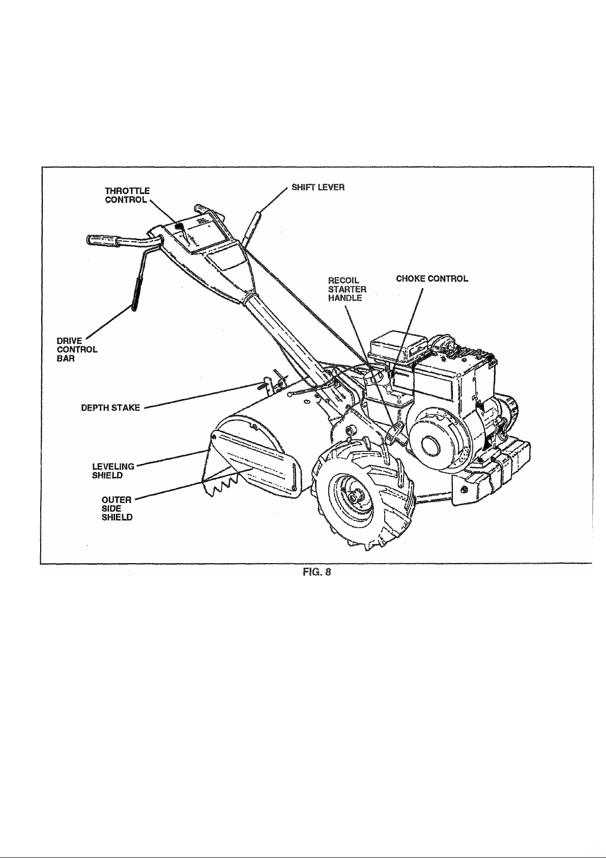
KNOW YOUR TILLER
READ THIS OWNER'S MANUAL AND SAFETY RULES BEFORE OPERATING YOUR TILLER.
Compare the illustrations with your tiller to familiarize yourself with the location of various controls and adjustments. Save this
manual for future reference.
A/IEETS ANSI SAFETY REQUIREMENTS
Our tillers conform to the safety standards of the American National Standards Institute.
THROTTLE CONTROL - Used to control engine speed.
DRIVE CONTROL BAR - Used to engage tiller.
DEPTH STAKE - Controls depth at which tiller will dig.
LEVELING SHIELD - Levels tilled soil.
OUTER SIDE SHIELD - Adjustable to protect small plants
from being buried,
SHIFT LEVER - Used to shift transmission gears.
RECOIL STARTER HANDLE - Used to start the engine.
CHOKE CONTROL - Used when starting a cold engine,
B
Page 9
OPERATION
The operation of any tiller can result in foreign objects thrown into the ay©S; which can
result In sever© ©y© damage. Always wear safety glasses or eye shields before starting
yoor tiller and while iilfing. We recommend wid© vision safety mask for over the spectacles
or standard safety glasses.
HOW TO USE YOUR TILLER
Know how to operate all controls before adding fuel and
oil or attempting to start engine.
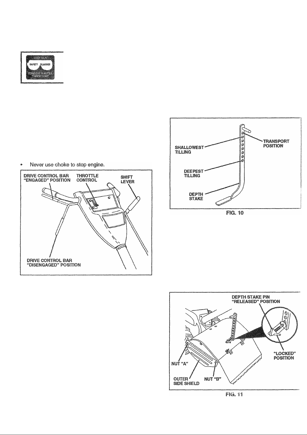
STOPPil^G (See Fig. 9)
TIMES AMD DRIVE
• Release drive control bar to stop movement.
• Move shift lever to “N” (neutral) position.
ENGINE
• Move throttle control to “STOP’ position.
FIG. 9
TIME OPERATION ■» WITH WHEEL DRIVE
• Always release drive control bar before moving shift
lever into another position.
• Tine movement is achieved by moving shift lever to “T’
(til!) position and engaging drive control bar.
DEPTH STAKE (See Fig. 10)
The depth stake can be raised or lowered to allowyou more
versatile tilling and cultivating, or to more easily transport
your tiller.
TILLING (See Fig. 11)
• Release depth stake pin. Pull the depth stake up for
increased tilling depth. Place depth stake pin in hole of
depth stake to lock in position,
• Place shift lever indicator in‘T position.
• Hold the drive control bar against the handle to start
tilling movement. Tines and wheels will both turn.
• Move throttle control to “FAST” position for deep tilling.
To cultivate, throttle* control can be set at any desired
speed, depending on how fast or slow you wish to
cultivate.
FORWARD - WHEELS ONLY/TINES STOPPED
• Release drive control bar and move shift lever indicator
to “F” (forward) position. Engage drive control bar and
tiller will move forward.
REVERSE WHEELS ONLY/TINES STOPPED
• DO NOT STAND DIRECTLY BEHIND TILLER.
• Release the drive control bar.
• Move throttle control to “SLOW” position.
• Move shift lever indicator to “R” (reverse) position.
• Hold drive control bar against the handle to start tiller
movement.
Page 10

OPERATION
TURNING
® Refease the drive control bar.
» Move throttle control to “SLOW” position.
• • Place shift lever indicator in “F" (forward) position.
Tines will not turn.
• Lift handle to raise tines out of ground.
• Swing the handle in the opposite direction you wish to
turn, being careful to keep feet and legs away from
tines.
• When you have completed your turn-around, release
the drive control bar and lower handle. Place shift lever
in “T (till) position and move throttle control to desired
speed, to begin tilling, hold drive control bar against
the handle.
OUTER SIDE SHIELDS (See Fig, 11)
The front edges of the outer side shields are slotted so that
the shields can be raised for deep tilling and lowered for
shallow tilling to protect small plants from being buried.
Loosen nut “A” in slot and nut “B”. Move shield to desired
position (both sides). Retighten nuts.
TRANSPORTING
CAUTION: Before lifting or transport
ing, allow tiller engine and muffler to
A
Release the depth stake pin. Move the depth stake
down to the top hole for transporting the tiller. Place
depth stake pin in hole of depth stake to lock in position.
This prevents tines from scuffing the ground.
Place shift lever Indicator in “F’ (forward) position for
transporting.
Hold the drive control bar against the handle to start
tiller movement. Tines will not turn.
Move throttle control to desired speed.
A
cool. Disconnectspark plug wire. Drain
gasoline from fuel tank.
CAUTION: Before operating your tiller
for the fl rst time, study this section and
the “SAFETY RULES” on page 2.
Always release drive control bar before
moving shift lever into another posi
tion.
Don’t back yourself into a solid ob
struction such as a tree, fence, etc.
BEFORE STARTING ENGINE
CHECK ENGINE OIL LEVEL (See Fig, 12)
IMPORTANT: BE VERY CAREFUL NOT TO ALLOW DIRT
TO ENTER THE ENGINE WHEN CHECKING OR ADDING
OIL OR FUEL. USE CLEAN SAE 30 OR 10W30 WEIGHT
OIL AND STORE IN APPROVED, CLEAN, COVERED
CONTAINERS. ALL OILS MUST MEET A.P.I. SERVICE
CLASSIFICATION SG. USE CLEAN FILL FUNNELS.
The engine in your unit has been shipped, from the
factory, already filled with SAE 30 summer weight oil.
With engine level, clean area around oil filler plug and
remove plug.
Engine oil should be to point of overflowing. For
approximate capacity see “PRODUCT SPECIFICA
TIONS” on page 3 of this manual. All oil must meet
A.P.I. Service Classification SG.
For cold weather operation you should change oil for
easier starting (See oil viscosity chart In the Customer
Responsibilities section of this manual).
To change engine oil, see the Customer Responsibili
ties section in this manual.
ADO GASOLINE
• Fill fuel tank. Use fresh, clean, regular unleaded
gasoline. (Use of leaded gasoline will Increase carbon
and lead oxide deposits and reduce valve life.
IMPORTANT: WHEN OPERATING IN TEMPERATURES
BELOW 32^F (0“C), USE FRESH, CLEAN, WINTER
GRADE GASOLINE TO HELP INSURE GOOD COLD
WEATHER STARTING.
WARNING: Experience indicates that alcohol blended
fuels (called gasohol or using ethanol or methanol) can
attract moisture which leads to separation and formation of
acids during storage. Acidic gas can damage the fuel
system of an engine while in storage. To avoid engine
problems, the fuel system should be emptied before stor
age of 30 days or longer. Drain the gas tank, start the
engine and let it run until the fuel lines and carburetor are
empty. Use fresh fuel next season. See Storage Instruc
tions for additional information. Never use engine or
carburetor cleaner products in the fuel tank or permanent
damage may occur.
CAUTION : Fill to within 1/2 inch (13mm)
of top of fuel tank to prevent spills and
to allow for fuel expansion. If gasoline
A
is accidentally spilled, move machine
away from area of spill. Avoid creating
any source of Ignition until gasoline
vapors have disappeared.
Do not overfill. Wipe off any spilled oil
or fuel. Do not store, spill or use gaso
line near an open flame.
10
Page 11

OPERATION
TO START ENGINE (See Fig. 13)
CAyTiOf^: Keep the tine control in
A
® Make sure spark plug wire is properly cormecied.
® Move shift lever indicaior to “N” (neutral) position.
• Place throttle control in “FAST position.
• Place choke control in “CHOKE” position if the engine
is cold. A warm engine may not require choking to start.
• Grasp starter handle with one hand and grasp the tiller
with other hand. Pul! rope out slowly until engine
reaches start of compression cycle (rope will pull
slightly harder at this point).
• Pull rope with a rapid, continuous, full arm stroke. Keep
a firm grip on starter handle and let rope rewind slowly.
Do not let starter handle snap back against starter.
• When engine starts, slowly move choke control on
engine halfway between “CHOKE” and “RUN” posi
tions and then to “RUN” position as engine warms up.
• Move throttle control to desired running position.
• Allow engine to warm up for a few minutes before
engaging tines.
NOTE: If at a high altitude (above 3000 feet/915 m) or in
cold temperatures (below 32°F/0°C), the carburetor fuel
mixture may need to be adjusted for best engine perfor
mance. See engine manual packed with your unit.
"OFF” position when starting engine.
TILLING HINTS
CAUTION: Until you are accustomed to
handling your tiller, start actual field
A
Tilling is digging Into, turning over, and breaking up
packed soil before planting. Loose, unpacked soil
helps root growth. Best tilling depth is 4” to 6" (1015
cm). A tilier will also clear the soil of unwanted
vegetation. The decomposition of this vegetable mat
ter enriches the soil. Depending on the climate (rainfall
and wind), It may be advisable to till the soil at the end
of the growing season to further condition the soil.
Soil conditions are important for proper tilling. Tines will
not readily penetrate dry, hard soil which may contrib
ute to excessive bounce and difficult handling of your
tiller. Hard soil should be moistened before tilling;
however, extremely wet soil will “ball-up” or clump
during tilling. Wait until the soil is less wet in order to
achieve the best results. When tilling in the fall, remove
vines and long grass to prevent them from wrapping
around the tine snaft and slowing your tilling operation.
For easier handling of your tiller, leave about 8 inches
(20 cm) of untilled soil between the first and second
tilling passes. The third pass will be between the first
and second (See Fig. 14).
Do not lean on handle. This takes weight off the wheels
and reduces traction. To get through a really tough
section of sod or hard ground, apply upward pressure
on handle or lower the depth stake.
use with throttle in slow position (mid
way between “FAST” and “IDLE”).
TINE SHEAS PmS
The tine assemblies on your tiller are secured to the tins
shaft with shear pins (See ‘TINE REPLACEMENT in thi
Service and Adjustments section of this manual).
If the tiller is unusually overloaded or jammed, the shea
pins are designed to break before internal damage occur;
to the transmission.
• If shear pin(s) break, replace only with those recom
mended by the manufacturer of your tiller.
11
Page 12

OPERATION
CULTIVATING
Cultivating is destroying the weeds between rows to pre
vent them from robbing nourishment and moisture from the
plants. At the same time, breaking up the upper layer of soil
crust will help retain moisture in the soil. Best digging depth
is 1" to 3“ (2.5"7.5 cm). Lower the outer side shields to
protect small plants from being buried.
* Cultivate up and down the rows at a speed which will
allow tines to uproot weeds and leave the ground in
rough condition, promoting no further growth of weeds
and grass (See Rg. 15).
» Replace clevis pin and hairpin clip on inside of wheel
and remove blocks.
» Repeat preceding steps on left hand side.
NOTE: In extremely rough conditions and while cultivating,
the wheels should be moved outward on the axle for
increased stability.
12
Page 13

CUSTOMER RESPONSIBILITIES
1 “ Change more often when operating under a heavy load or in high ambient temperatures,
2 ~ Service more often when operating in dirty or dusty conditions.
GENERAL RECOMMENDATIONS
The warranty on this unit does not cover items that have
been subjected to operator abuse or negligence. To
receive full value from the warranty, the operator must
maintain unit as Instructed in this manual.
Some adjustments will need to be made periodically to
properly maintain your unit.
All adjustments in the Service and Adjustments section of
this manual should be checked at least once each
season.
• Onceayearyou should replace the spark plug, replace
air fitter, and check tines and belts for wear. A new
spark plug and clean air filter assure proper air-fuel
mixtu re and help you r engine run better and last longer,
BEFORE EACH USE
• Check engine oil level.
• Check tine operation.
• Check for loose fasteners.
LUBRiCATiOM
Keep unit well lubricated {See “LUBRICATION CHART”).
LUBRICATION CHART
THROTTLE
CONTROL
SAE 30 OR 10W-30 MOTOR OIL
‘ REFER TO CUSTOMER RESPONSIBILITIES “ENGINE” SECTIO
13
Page 14

CUSTOMER RESPONSIBILITIES
Disconnect spark plug wire before performing any maintenance (except carburetor adjustment) to
prevent accidental starting of engine.
Prevent fires! Keep the engine free of grass, leaves, spilled oil, or fuel. Remove fuel from tank before
A
tipping unit for maintenance. Clean muffler area of all grass, dirt and debris.
Do not touch hot muffler or cylinder fins as contact may cause burns.
ENGINE
LUBRICATION
Change the olí after the first two hours of operation and
every 25 hours thereafter or at least once a year if the tiller
Is not used for 25 hours in one year.
Check the crankcase oil level before starting the engine
and after each five (5) hours of continuous use. Add SAE
30 motor oil or equivalent Tighten oil filler plug securely
each time you check the oil level. SAE 5 W-30 motor oil may
be used to make starting easier in areas where temperature
is consistently 32^ F (0°C) or lower.
TO CHANGE ENGINE OIL (See Figs. 18 and 19)
Determine temperature range expected before oil change.
All oil must meet API service classification SG.
• Be sure tiller is on level surface.
• Oil will drain more freely when warm.
• Catch oil in a suitable container.
• Remove drain plug.
» Tip tiller forward to drain oil.
• After oil has drained completely, replace oil drain plug
and tighten securely.
• Remove oil filler plug. Be careful not to allow dirt to
enter the engine.
• Refill engine with oil. See “CHECK ENGINE OIL
LEVEL” In the Operation section of this manual.
AIR CLEANER (See Fig. 20)
Replace aircleanercarthdge every twenty-five hours, more
often if engine is used in very dusty conditions.
" Loosen air cleaner screws, one on each side of cover.
• Remove air cleaner cover.
» Carefully remove air cleaner cartridge. Be careful. Do
not allow dirt or debris to fall into carburetor.
• install new air cleaner cartridge. Clean and replace
cover. Tighten screws securely.
NOTE: Do not attempt to clean or oil the paper cartridge.
FIG. 18
COOLING SYSTEM (See Fig. 21)
Your engine is air cooled. For proper engine performance
and long life keep your engine clean.
• Clean air screen frequently using a stiff-bristled brush,
• Remove blower housing and clean as necessary.
• Keep cylinder fins free of dirt and chaff.
14
Page 15

CUSTOMER RESPONSIBILITIES
lyUFFLER
Do not operate tiller without muffler. Do not tamper with
exhaust system. Damaged mufflers or spar1< arresters
could create a fire hazard. Inspect periodically and replace
if necessary. If your engine is equipped with a spark
arrester screen assembly, remove every 50 hours for
cleaning and inspection. Replace if damaged.
SPARK PLUG
Replace spark plugs at the beginning of each tilling season
or after every 50 hours of use, whichever comesfirst. Spark
plug type and gap setting is shown in “PRODUCT SPEC!-
FI CATIONS” on page 3 of this manual.
SERVICE AND ADJUSTMENTS
CAUTION; Disconnect spark plug wires from spark plug and place wire where It cannot come Into
A
TILLER
contact with plug.
TRANSMISSION
Your transmission is sea led and will only require lubrication
if serviced.
CLEANING
• Clean engine, wheels, finish, etc. of all foreign matter.
• Keep finished surfaces and wheels free of all gasoline,
oil, etc.
• Protect painted surfaces with automotive type wax.
We do not recommend using a garden hose to clean your
unit unless the muffler, air filter and carburetor are covered
to keep water out. Water in engine can result in a shortened
engine life.
TIRE CARE
TO ADJUST HANDLE HEIGHT (See Fig. 22)
Select handle height best suited for your tilling conditions.
Handle height will be different when tiller digs into soil,
• First loosen handle lock lever,
• Handle can be positioned at different settings between
“HIGH” and “LOW” positions.
• Retighten handle lock lever securely after adjusting.
CAUTION: When mounting tires, un
less beads are seated, overinfiatlon
A
• Maintain 20 PSl (1,4 k^cm^) of tire pressure. If tire
pressures are not equal, tiller will pull to one side.
• Keep tires free of gasoline or oil which can damage
rubber.
can cause an explosion.
TO REMOVE WHEEL (See Fig. 23)
• Place blocks under transmission to keep tiller from
tipping.
• Remove hairpin clip and clevis pin from wheel.
• Remove wheel and tire.
• Repair tire and reassemble.
IS
Page 16

service and adjustments
TO REMOVE BELT GUARD (See Fig. 24)
NOTE; For ease of removal, remove hairpin dip and clevis
pin from left wheel. Pull wheel out from tiller about 1 inch
(2.5 cm).
» Remove two (2) cap nuts and washers from side of belt
guard.
® Remove hex nut and washerfrom bottom of belt guard
(located behind wheel).
® Puli belt guard out and away from unit.
Replace belt guard by reversing above procedure.
TO REPLACE GROUND DRIVE BELT (Se
Figs. 24 and 25)
® Move left wheel and remove belt guard as described
“TO REMOVE BELT GUARD”.
• Loosen belt guides “A” and “B” and also nuts “C” ar
“D”.
• Remove old belt by slipping from engine pulley first
® Place new belt in groove of transmission pulley ar
into engine pulley. BELT MUST BE IN GROOVE O
TOP OF IDLER PULLEY. NOTE POSITION OF BEl
TO GUIDES.
• Tighten belt guides “A” and “B” and nuts “C” and “D
• Check belt adjustment as described below.
• Replace belt guard.
• Reposition wheel and replace clevis pin and hairp
clip.
GROUND DRIVE BELT ADJUSTMENT (Se
Fig. 25)
For proper belt tension, the extension spring should ha\
about 5/8 inch (16 mm) stretch when drive control bar is
“ENGAGED” position. This tension can be attained t
follows:
• Loosen cable clip screw securing the drive contr
cable.
• Slide cable forward for less tension and rearward fi
more tension until about 5/8 inch stretch is obtains
while the drive control bar is engaged.
• Tighten cable clip screw securely.
NUT “C”
NUT “D
ENGINE
PULLEY
IDLER
PULLEY
TRANSMISSION
PULLEY
BELT
GUIDE “A”
CABLE CLIP
SCREW
DRIVE
CONTROL
CABLE
FIG. 25
16
Page 17

SERVICE AND ADJUSTMENTS
. hNE REPLACEMENT (See Figs« 26, 27 and
28) .
CAUTION: Tines are sharp. Wear
qloves or other protection when han
A
A badly worn tine causes your tiller to work harder and dig
more shallow. Most important, worn tines cannot chop and
shred organic matter as effectively nor bury it as deeply as
good tines. A tine this worn needs to be replaced.
dling tines.
To maintain the superb tilling performance of this
machine the tines should be checked for sharpness,
wear, and bending, particularly the tines which are next
to the transmission. If the gap between the tines
exceeds 3-1/2 inches (9cm), they should be replaced
or straightened as necessary.
New tines should be assembled as shown in Fig. 28.
Sharpened tine edges will rotate rearward from above.
SHARP EDGE
SHEAR PIN
FIG. 26
HAIRPIN CUP
HAIRPIN CUP
SHARP EDGE
SHEAR PIN
FIG. 28
17
Page 18

SERVICE AND ADJUSTMENTS
ENGINE
TO ADJUST THROTTLE CONTROL CABLE
(See Fig. 29)
® Loosen cable clamp screw to allow cable to move.
» Move throttle control lever on upper handle to “FAST
position.
® Puli throttle cable out until engine belicrank is back as
far as it will go.
® Hold cable in this position and tighten clamp screw
securely. ,
TO ADJUST CARBURETOR
The carburetor has been preset at the factory and adjus
ment should not be necessary. However, minor adjus
ments may be required to compensate for differences ;
fuel, temperature, altitude or load. If the carburetor doe
need adjustment, see the engine manual packed with yoi
unit.
IMPORTANT: NEVER TAMPER WITH THE ENGIN
GOVERNOR, WHICH IS FACTORY SET FOR PROPE
ENGINE SPEED. OVERSPEEDING THEENGINE ABOV
THE FACTORY HIGH SPEED SETTING CAN B
DANGEROUS. IF YOUTHiNKTHE ENGINE-GOVERNE
HIGH SPEED NEEDS ADJUSTING, CONTACT YOU
NEAREST AUTHORIZED SERVICE CENTER, WHICH HA
THE PROPER EQUIPMENT AND EXPERIENCE TO MAK
ANY NECESSARY ADJUSTMENTS,
18
Page 19

STORAGE
/mmediatety prepare your tiller for storage at the end of the
season or If the unit will not be used for 30 days or more.
CAUTION: Never store the tiller with
gasoline in the tank inside a building
where fumes may reach an open flame
or spark. Allow the engine to cool
before storing In any enclosure.
TILLER
• Clean entire tiller (See "CLEANING” in the Customer
Responsibilities section of this manual).
• Inspect and replace belts, if necessary (See belt re
placement instructions in the Service and Adjustments
section of this manual).
• Lubricate as shown in the Customer Responsibilities
section of this manual.
• Be sure that ail nuts, bolts and screws are securely
fastened. Inspect moving parts for damage, breakage
and wear. Replace if necessary.
• Touch up all rusted or chipped paint surfaces; sand
lightly before painting.
ENGINE
^UEL SYSTEM
IMPORTANT: IT IS IMPORTANT TO PREVENT GUM
DEPOSITS FROM FORMING IN ESSENTIAL FUEL
SYSTEM PARTS SUCH AS THE CARBURETOR. FUEL
FILTER. FUEL HOSE, OR TANK DURING STORAGE.
ALSO, EXPERIENCE INDICATES THAT ALCOHOL
BLENDED FUELS (CALLED GASOHOL OR USING
ETHANOL OR METHANOL) CAN ATTRACT MOISTURE
WHICH LEADS TO SEPARATION AND FORMATION OF
ACIDS DURING STORAGE. ACIDIC GAS CAN DAMAGE
THE FUELSYSTEM OFAN ENGINEWHILE IN STORAGE.
• Drain the fuel tank.
• Start the engine and let it run until the fuel lines and
carburetor are empty.
• Never use engine or carburetor cleaner products in the
fuel tank or permanent damage ma^ occur.
• Use fresh fuel next season.
NOTE: Fuel stabilizer is an acceptable alternative in
minimizing the formation of fuel gum deposits during stor
age. Add stabilizer to gasoline In fuel tank or storage
container. Always follow the mix ratio found on stabilizer
container. Run engine at least 10 minutes after adding
stabilizer to allow the stabilizer to reach the carburetor. Do
notdrainthe gas tank and carburetor if using fuel stabilizer.
ENGINE OIL
Drain oil (with engine warm) and replace with dean oil.
(See“ENGINE” in the Customer Responsibilities section of
this manual).
CYLINDERS
• Remove spark plug.
• Pour 1 ounce (29 ml) of oil through spark plug hole into
cylinder.
• Puli starter handle slowly several times to distribute oil.
• Replace with new spark plug.
OTHER
• Do not store gasoline from one season to another.
• Replace your gasoline can if your can starts to rust.
Rust and/or dirt in your gasoline will cause problems.
• If possible, store your unit indoors and cover it to give
protection from dust and dirt.
• Cover your unit with a suitable protective cover that
does not retain moisture. Do not use plastic. Plastic
cannot breathe which allows condensation to form and
will cause your unit to rust.
IMPORTANT: NEVER COVER TILLER WHILE ENGINE
AND EXHAUST AREAS ARE STILL WARM.
19
Page 20

TROUBLESHOOTING POINTS
PñOBLEy
WiH not start
Hard to start
Loss of power
CAUSE
1. Out of fuel.
2. Engine not "CHOKED” properly,
3. Engine flooded,
4. Dirty air cleaner.
5. Water in fuei.
6. Clogged fuel tank.
7. Loose spark plug wire.
S. Bad spark plug or improper gap.
9. Carburetor out of adjustment.
1.
Throttle control not set property.
2.
Dirty air cleaner.
3.
Bad ^ark plug or improper gap.
4.
Stale or dirty fuel.
5.
Loose spark plug wire.
6.
Carburetor out of adjustment
1. Engine is overloaded.
Dirty air cleaner.
2.
3.
Low oil levei/dirty oil. 3.
4.
Faulty spark plug. 4. Clean and regap or change spark plug.
5. Oil in fuel.
6. Stale or dirty fuel.
7,
Water in fuel. Drain fuel tank and carburetor, and refill tank witii fresh
8.
Clogged fuei tank. 8. Remove fuel tank and clean.
9.
Spark plug wire loose. 9. Connect and tighten spark plug wire.
10. Dirty engine air screen.
Dirty/clogged muffler.
11.
12, Carburetor out of adjustment.
13.
Poor compression. I 13. Contact an authorized service center.
CORRECTION
1. Fill fuel tank.
2. Sea 'TO START ENGINE” in Operation section.
3. Wait several minutes before attempting to start.
4. Replace air cleaner cartridge.
5. Drain fuel tank and carburetor, and refill tank wifii fresh
gasoline.
6. Remove fuel tank and clean.
7. Make sure spark plug wire is seated properly on plug.
8. Replace spark plug or adjust gap.
9. Make necessary adjustments.
1. Place throttle control in “FAST’ position.
2. Replace air cleaner cartridge.
3. Replace spark plug or adjust gap.
4. Drain fuel tank and refill \wth fresh gasoline.
5. Make sure spark plug wire is seated properly on plug.
6. Make necessary adjustiments.
1, Set depth stake for shallower tilling.
2. Replace air cleaner cartridge.
Check oil tevei/change oil.
5. Drain and clean fuel tank and refill, and clean carburetor.
Drain fuel tank and refill with fresh gasoline.
6.
gasoline.
10. Clean engine air screen.
Clean/replace muffler.
11.
12.
Make necessary adjustments.
Engine overheats
Excessive bounce/
difficult handling
Soil balls up or clumps
Engine runs but tiller
won’t move
Engine runs but labors 1.
when tilling
Tines will not rotate 1.
1.
Low oil level/dir^ oil.
2.
Dirty engine air screen.
3.
Dirty engine.
4.
Partially plugged muffler.
5.
Improper carfoutoior adjustment
1. Ground too dsy and hard.
1. Ground too wet.
1.
Drive control bar is not engaged.
2.
V-be!l not correctly adjusted.
3.
V-be!t is off pylley(s).
Tiliing too deep.
2.
Throttle control not properly adjusted.
3.
Carburetor out of adjustment.
Shear pin(s) broken.
1. Check oil level/change oil.
2. Clean engine air screen.
3. Clean cylinder fins, ar screen, and muffler area.
4. Remove arvd dean muffler.
6. Adjust carburetor to richer position.
1. Moisten ground or wait for more favorable soil
conditions.
1, Wait for more favorable soil conditions.
Engage drive control,
Inspect/adjust V-belt.
1
inspect V-beit.
I 3.
Set depth stake for shallower tilling.
Check throttle control setting.
1
Make necessary adjustments.
1
Replace shear pin{s).
20
Page 21

REPAIR PARTS
5 HP 17" TILLER - ■ MODEL NO. PPRT5, PRODUCT NO. 954 00 62-21
HANDLE ASSEMBLY i
KEY
NO.
1
2
3
4
5
6
7
8
9
10
11
12
13
14
15
16
17
PART
NO.
871091008
532126951
532104164
532124797
532124788
532081328
532109335
532109313
532109337
872110608
532109229
532005394
819131611
532109228
532125327
810040400
873220400
DESCRIPTION
Screw, Truss Hd.
#10-24 UNCxl/2
Panel, Control
Tie, Cable
Grip, Handle #10-24x1/2
Clip, Hairpin
Bolt, Shoulder
Handle, Shift
Grommet, Rubber
Rod, Shift
Bolt, Carriage 3/8-16x1 Gr. 5
Lock, Handle
Nut 3/8-16
Washer 13/32 x l x 11 Ga.
Lever, Lock, Handle
Handle
Washer, Lock 1/4
Nut, Hex 1/4-20
KEY
NO.
18
19
20
21
22
23
24
25
26
27
PART
NO.
873731000
532102162
532009484
532086777
532102604
532102744
532105216
532127012
872140404
532009266
532132327
532102721
- -
532134242
- -
532120431
NOTE: All comoonent dimensions given in U.S. inch
1 inch =:
DESCRIPTION
Nut. Keps #10-24 UNC
Cable, Clutch
Clip
Screw, Hex Washer Hd. Slotted
Grip, Bar, Control
Clamp, Bar, Control
Bar Assembly, Control
Control, Throttle
Bolt, Carriage 1/4-20 UNC x 1/2
Grip, Handle
Manual, Owner’s
Decal, Instruction
Decal, Control Panel
Decal, Hand Placement
25.4 mm
21
Page 22

REPAIR PARTS
5 HP 17" TILLER - - MODEL NO. PPRT5, PRODUCT NO. 954 00 62-21
MAINFRAME, LEFT SIDE
3
KEY
NO. NO.
2
3
4
5
6 532110111
7
8
9
10
11
12
13
14
15
16
17
18
19
20
21
22
23
24
25
26
PART DESCRIPTION
873510500
1
810040600
873220600
874930568 Bolt, Hex 5/16-18x4-1/4
532124963 Pin, Roll
872110404 Bolt, Carriage 1/4-20 x 1/2 Gr. 5
532008700
532086777 Screw, Hex, Washer Head, Slotted
532009484
810040400
873220400 Nut, Hex 1/4-20
823230506 Screw, Set, Hex 5/16-18 x 3/8
532120938
819111116
532100473
873220500
532110651
532002649 Key, Square 3/16 x 1-1/8
532110653
532131691
532104214
532102190 Tire
532124258
532124718
532126875
532124788
532125341
Nut, Keps 5/16-18
Washer, Lock 3/8
Nut, Hex 3/8-16
Lever, Shift
Plate, Shift Indicator
#10-24x1/2
Clip
Washer, Lock 1/4
Spacer, Split 0,327 x 0.42 x 2,68
Washer 11/32x 11/16 x 16 Ga.
Sheave, Transmission
Nut, Hex 5/16-18
Spacer, Split 0.327 x 0.42 x 1.75
Guard, Pinch Point
Spacer, Split 0.327 x 0.42 x 1.627
Nut, Cap 5/16-18
Rim
Tire Valve
Rivet, Drilled
Clip, Hairpin
Guard, Belt
KEY
NO.
27 532132672 Belt, V
28
29 812000032 Ring, Klip
30 532105611
31 532102384 Bolt, Hex 5/16-16 X 12
32
33
34
35
36 532102331
37
38
- -
PART
NO.
532104679
532102141
874760616 Bolt, Hex 3/8-16 X 1
532102383 Counterweight, L. H,
874760524 Bolt, Hex 5/16-18x1-1/2
532130816 Sheave, Engine
532131558
532102180 Decal, Shift Indicator
532132328
DESCRIPTION
Pulley, Idler
Bracket, Idler
Shaft, Idler Arm
Bracket, Reinforcement, L. H.
Bracket, Guard Belt
Decal, Logo (Belt Guard)
NOTE: All component dimensions given in U.S. inches.
1 inch = 25,4 mm
22
Page 23

REPAIR PARTS
5 HP 17*‘ TILLER»- MODEL NO- PPRT5, PRODUCT NO. 954 00 62»21
MAiNFRAyE, RIGHT SIDE
KEY PART
NO. NO.
1 873510500
2 532102332
3 874760524
4 532102173
5 810040600
6 873220600
7 532124788
8 532126875
DESCRIPTION
Nut. Keps 5/16-18
Bracket, Reinforcment
Bolt, Hex 5/16-18x1-1/2
Counterweight, R.H.
Washer, Lock 3/8
Hut, Hex 3/8-16
Clip. Hairpin
Rivet, Drilled
KEY PART
NO. NO.
9 532102190
532124258
532124718
10
532121543
532110593
DESCRIPTION
Tire
Rim
Tire Valve
Engine, Briggs & Stratton
Model No. 130202
Decal, Engine
Decal, Caution (Top of Engine)
NOTE: All component dimensions given in U.S.inches,
1 inch - 25.4 mm
23
Page 24

REPAIR PARTS
5 HP 17“ TILLER - - MODEL NO. PPRT5, PRODUCT NO. 954 00 62-21
TRANSMISSION
^^4 52
¿5
KEY PART
NO.
10
11 532100371
12 532106160
13 532102107
14 532008353
15 812000039
16 532102109
17 532104159
18 532004358
19 812000040
20 532102114
21 532102115
22
23
24
NO.
1 532132718
532121147
2
3
532106211
4
532005020
5 532001370
6 532102113
7 532102110
8 532124792
9
532102136
532124697
532006803
532102111
810040700
DESCRIPTION
Transmission Assembly
(Includes Key Nos. 2-52)
Gearcase, L.H. w/Bearing
(Includes Key No. 4)
Gasket, Gearcase
Bearing, Needle
Washer, Thrust 5/8x 1.1 Ox 1/32
Pinion, input
Shaft, input
Bearing, Needle
Washer, Seal
Ball, Steel
Spring, Shift, Fork
O-Ring
Arm,, Shift
Fork, Shift
Ring, Klip
Shaft, Shift
Spacer, Split
Washer
Ring, Klip
Gear, Assembly, Reverse Idler
(Includes Key Nos. 21 and 22)
Gear, Reverse Idler
Bearing, Needle
Shaft, Reverse Idler
Washer, Lock 7/16
KEY
NO.
25
26
27
28
29
30
31
32
33
34
35
36
37
38
39
40
41
42
43
44
45
46
47
48
49
50
51
52
PART
NO.
873610700
532102128
532102100
532106390
532102134
532109204
532102106
532106388
532102121
532102112
532102101
532106141 Sprocket Assembly w/Bearing
532124791 Bearing, Needle
532106142
532105345 Gear, Cluster, Red 1st & 2nd
532105346
532008358 Shaft, Reduction (1st)
532004220
532106146
532009672 Cup, Formed
532102144
532009676 Seal, Ring, Rubber
532009674 Seal, Oil
532121745
532132688
532106147 Chain, Roller #50-50 Pitch
817580408
873220500
532006066
DESCRIPTION
Nut, Hex 7/16-20
0-Rlng
Bearing, Shaft, Ground Drive
Spacer 0.765 x 1.125 x 1.23
Chain #35-60 Pitch
Ground Shaft Assembly
Bearing, Shaft, Ground Drive
Spacer 0,70 x 1.00 x 1,150
Sprocket and Gear Assembly
Shaft. Reduction (2nd)
Screw, Whiz, Lock 5/16-18 x 3-1/2
(includes Key Nos. 37 and 38)
Sprocket, Tine
Gear, Reverse
Washer, Thrust
Spacer 1.01 x 1,75 x 0.760
Ring, Spiral
Gearcase, R.H. w/Bearing
(Includes Key No. 8)
Shaft, Tine
Screw 1/4-20x1/2
Nut, Hex 5/16-18
Grease, Plastilube #1
NOTE: All component dimensions given In U.S. inches.
1 inch - 25.4 mm
24
Page 25

REPAIR PARTS
5 HP 17" TILLER - - MODEL NO. PPRT5, PRODUCT NO. 954 00 62-21
"JNE SHIELD
KEY
HO,
10
11
12
13
14
■i6
17
PABT
HO,
898000129
1
532125001
2
532008393 Pin, Stake, Depth
3
4
812000036
5
872110508
532008394
6
7
532008392
8
532109230
532124713
9
872140506
873220500
810040500 Washer, Lock 5/16 29
872110510
532124343
]
532125002
873220400
810040400
DESGBIPTIOM
Nut, Flange 5/16-18 18
Shield, Side, Outer L. H.
Ring, Klip
Bolt, Carriage 5/16-18 x 1
Spring
Bracket, Latch
Spring, Depth Stake
Shield, Tine
Bolt, Carriage 5/16-18x3/4 Gr 5 27
Nut, Hex 5/16-18
Bolt, Carriage 5/16-18 x 1-1/4
Bracket, Shield Tine
Shield, Side, Outer R.H.
Nut, Hex 1/4-20
Washer, Lock 1/4
KEY
m.
19
20
21 532102156
22
23
24
25
26
28
NOTE: All component dimensions given in U.S. inches.
PART
NO.
872040410
532102701
873220600
874930632
532004440
872140404
532124717
532109227
532124714
532120588
532124715
532124263
532120075
1 inch = 25.4 mm
DESCRIPTION
Bolt, Carriage 1/4-20 x 1-1/4 Gr. 5
Grip
Nut, Hex 3/8-16
Stake, Depth
Bolt, Hex 3/8-16x2
Hinge
Bolt, Carriage 1/4-20 x 1/2 Gr. 5
Cap. Vinyl
Pad, Idler
Shield, Leveling
Pin, Hinge
Shield, Side
Decal, Tine Shield
Decal, Warning (Leveling Shield)
25
Page 26

REPAIR PARTS
5 HP 17" TILLER - - MODEL NO. PPRT5, PRODUCT NO. 954 00 62-21
TINE ASSEMBLY
/;? V
/'-‘“I /. .-> ,
x/^" ii : ..y
X #V
(¿c\ ' _
0
"i
11^*^
>
KEY PART
MO. NO.
1 532004459
2 532132673
3 532006554
4 532124660
5 532132727
6 873610600
7 810040600
DESCRIPTION
Tine, Outer, L.H.
Pin, Shear
Tine, inner, L.H.
Clip, Hairpin
Assembly, Hub and Plate, L.H.
Nut, Hex 3/8-24
Washer, Lock 3/8
KEY
NO.
10
11
NOTE: All component dimensions given in U.S. inches.
26
PART
NO.
874610616 Bolt, Hex 3/8-24 x 1
8
532004460
9
532132728 Assembly, Hub and Plate, R.H.
532006555 Tine, Inner, R.H.
1 inch = 25.4 mm
DESCRIPTION
Tine, Outer, R.H.
Page 27

r
The Manufacturer warrants to the original consumer purchaser that this product as manufactured is free
from defects in materials and workmanship. For a period of two (2) years from date of purchase by the
original consumer purchaser^ wewill repair or replace, at our^option, without ^charge for parts or labor
incurred in replacing parts, any part which we find to be defective due to materials or workmanship. This
Warranty is subject to the following limitations and exclusions,
1. This warranty does not apply to the engine or components parts thereof. Please refer to the applicable
manufacturer's warranty on these items,
2. Transportation charges for the movement of any power equipment unit or attachment are the responsi
bility of the purchaser. Transportation charges for any parts submitted for replacement under this
warranty must be paid by the purchaser unless such return is requested by The Manufacturer.
3. The Warranty period for any products used for rental or commercial purposes- is limited to 90 days from
the date of original purchase.
4. This Warranty applies only to products which have been properly assembled, adjusted, operated, and
maintained in accordance with the instructions furnished. This Warranty does not apply to any product
which has been subjected to alteration, misuse, abuse, improper assembly or installation, delivery daiH“
age, or to normal wear of the product.
6, Exclusions: Excluded from this Warranty are belts, tines, tine adapters, normal wear, normal adijust--
ments, standard hardware and normal maintenance.
6. In the event you have a claim under this Warranty, you must return the product to an authorized
service dealer.
Should you have any unanswered questions eonceming this Warranty, please contact:
LIMITED WARRANTY
In U.S,A. contact:
Poulan/Weed Eater
Service Department
P.0, Box 9329
Shreveport, LA 71139-9329
Phone: (318)687-0100
giving the model number, serial number and date of purchase of your product and the name and address of
the authorized dealer from whom it was purchased,
THIS WARRANTY DOES NOT APPLY TO INCIDENTAL OR CONSEQUENTIAL DAMAGES AND ANY
IMPLIED WARRANTIES ARE LIMITED TO THE SAME TIME PERIODS STATED HEREIN FOR OUR
EXPRESSED WARRANTIES. Some areas do not allow the limitation of consequential damages or limita
tions of how'long an implied Warranty may last, so the above limitations or exclusions may not apply to you.
This Warranty gives you specific legal rights, and you may have other rights which vary from locale to
locale.
This is a limited Warranty within the meaning of that term as defined in the M^nuson-Moss Act of 1975,
In Canada contact:
Poulan/Weed Eater
549 Canada Avenue
Huron Park, - Ontario
Canada NOMIYO
Phone: (519)228-6514
27
Page 28

PARTS AND SERVICE
Yonr POULAN PHO product has been expertly eugmeered and carefully manufactured to rigid
quality standards. As with all mechanical products, some adjustments or part replacement may be
necessary during the life of your unit.
FOR SERVICE OR REPLACEMENT PARTS?
1 Consult your dealer/place of purchase,
2. Consult the yello w pages of your phone directory for the name of the nearest Poulan/Weed Eater
Master Service Dealer (under “saws” for Chain Saws or under “lawn mowers” for Trimmers,
Brushcutters, and Blowers).
3. For replacement parts, have available the following information:
a. Description of the tool.
b. Model Number.
c. Description of part.
NOTE; Poulan/Weed Eater Division provides parts and service through its authorized distribu
tors and dealers; therefore, all requests for parts and service should be directed to your
local dealer (s). The philosophy of Poulan/W eed Eater Division is to continually improve
all of its products. If the operating characteristics or the appearance of your product
differs from those described in this Operator’s Manual, please contact your local Poulan/
Weed Eater Dealer for updated information and assistance. Always update your tool
when improvements are made available, especially those related to safety. Parts and
repair service are not available directly from Poulan/Weed Eater Division White
Consolidated Industries, Inc.
POULAN/WEED EATER
DIVISION WHITE CONSOLIDATED INDUSTRIES, INC.
Shreveport, Louisiana 71139-9329 mmmmm
954 00 62-21
© 1991 Poiilao/Weed Eater Division White Consolidated Industries, In
632132327 10.24.9
Printed inU.S./
 Loading...